US7284789B2 - Crossmember - Google Patents
Crossmember Download PDFInfo
- Publication number
- US7284789B2 US7284789B2 US10/512,942 US51294204A US7284789B2 US 7284789 B2 US7284789 B2 US 7284789B2 US 51294204 A US51294204 A US 51294204A US 7284789 B2 US7284789 B2 US 7284789B2
- Authority
- US
- United States
- Prior art keywords
- crossmember
- basic body
- elements
- wall
- rib elements
- Prior art date
- Legal status (The legal status is an assumption and is not a legal conclusion. Google has not performed a legal analysis and makes no representation as to the accuracy of the status listed.)
- Expired - Fee Related, expires
Links
Images


Classifications
-
- B—PERFORMING OPERATIONS; TRANSPORTING
- B62—LAND VEHICLES FOR TRAVELLING OTHERWISE THAN ON RAILS
- B62D—MOTOR VEHICLES; TRAILERS
- B62D29/00—Superstructures, understructures, or sub-units thereof, characterised by the material thereof
- B62D29/001—Superstructures, understructures, or sub-units thereof, characterised by the material thereof characterised by combining metal and synthetic material
-
- B—PERFORMING OPERATIONS; TRANSPORTING
- B62—LAND VEHICLES FOR TRAVELLING OTHERWISE THAN ON RAILS
- B62D—MOTOR VEHICLES; TRAILERS
- B62D25/00—Superstructure or monocoque structure sub-units; Parts or details thereof not otherwise provided for
- B62D25/08—Front or rear portions
- B62D25/14—Dashboards as superstructure sub-units
- B62D25/145—Dashboards as superstructure sub-units having a crossbeam incorporated therein
-
- B—PERFORMING OPERATIONS; TRANSPORTING
- B62—LAND VEHICLES FOR TRAVELLING OTHERWISE THAN ON RAILS
- B62D—MOTOR VEHICLES; TRAILERS
- B62D29/00—Superstructures, understructures, or sub-units thereof, characterised by the material thereof
- B62D29/001—Superstructures, understructures, or sub-units thereof, characterised by the material thereof characterised by combining metal and synthetic material
- B62D29/004—Superstructures, understructures, or sub-units thereof, characterised by the material thereof characterised by combining metal and synthetic material the metal being over-moulded by the synthetic material, e.g. in a mould
Definitions
- the invention relates to a crossmember for a motor vehicle.
- DE 100 46 120 A1 describes a component of hybrid construction for a motor vehicle, in particular a crossmember for the cockpit region, in which the crossmember is designed as a lightweight component with a shell-shaped basic body and with reinforcing ribs consisting of molded-on plastic.
- the crossmember is designed as a lightweight component with a shell-shaped basic body and with reinforcing ribs consisting of molded-on plastic.
- at least one duct is entirely or partially injection molded together with the reinforcing ribs in the interior of the basic body.
- the duct serves, for example, for conducting air of an air conditioning system.
- a component of this type leaves something to be desired.
- the invention provides a crossmember for a motor vehicle, in particular for the cockpit region, in which at least one wall running transversely with respect to the crossmember is provided.
- a wall is provided at the ends of the crossmember (A-pillar connection), in the region of the connection for the airbag, steering system and tunnel strut and wherever else holders are required.
- a passage is preferably provided between the wall and basic body.
- an air duct which is part of an air conditioning system can run through the passage, but also a duct for the wiping water for the headlights or the windshield, cooling water, oil, compressed air or the like, if appropriate also for the protected laying of cables, petrol lines, oil lines, compressed air lines or the like may also be provided.
- the air duct may be inserted or injection molded, for example. The insertion or injection molding of the air duct affords the advantage of enabling plastics which are more reasonably priced to be used, since the static is absorbed by the other elements, in particular by the basic body, the walls and optionally provided reinforcements, which are manufactured in particular from metal.
- the wall preferably consists of a metal sheet, in particular of steel, aluminum of magnesium, and has connections at which the crossmember can be attached to an A-pillar or the like or at which other elements can be attached to the crossmember.
- a metal sheet in particular of steel, aluminum of magnesium, and has connections at which the crossmember can be attached to an A-pillar or the like or at which other elements can be attached to the crossmember.
- other metals in particular high-strength metals, may also be used.
- the wall preferably forms part of the elements which are to be attached to the crossmember, such as, for example, the A-pillar connection, the steering system, the support for the scuttle, the holder for the gearshift mechanism, electronic box, glove compartment, airbag, knee bag, instrument panel, the channel strut, the pedal block and the central consoles.
- the walls or their functions are integrated directly in the attachment element or the wall entirely or partially takes on the functions of the attachment elements, for example forms parts of an airbag housing.
- the attachment elements and the walls may also, however, be of multi-part design. This enables a further reduction in weight to be achieved.
- the crossmember, for reinforcement preferably has ribs, rib elements and/or tension elements and/or compression elements which are attached to the basic body.
- the reinforcement is preferably a cast part, sintered part or forged part which is manufactured, in particular, from steel, aluminum or magnesium.
- the wall may, for example, also be integrated directly in the reinforcement, i.e. may be part of the reinforcement.
- the reinforcing elements are arranged at angle of 45° +/ ⁇ 10° with respect to the longitudinal direction of the crossmember if the crossmember is subject to bending and torsional loading.
- the crossmember for reinforcement, has ribs, rib elements and/or tension elements which are attached to the basic body and are arranged at angle of 0° or 90° with respect to the longitudinal direction of the crossmember.
- the rib elements have a V-shaped design and are preferably attached to one another in such a manner that they are fixed with the ends of their limbs to the basic body and with their central regions to each other.
- elements which correspond to a plurality of rib elements connected in such a manner may also be provided.
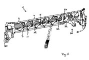
- FIG. 1 shows a perspectively illustrated crossmember according to the first exemplary embodiment
- FIG. 2 shows an illustration of a wall in a basic body according to the first exemplary embodiment
- FIG. 3 shows an illustration of a variant to FIG. 2 .
- FIG. 4 shows an illustration of a rib element according to FIG. 1 .
- FIG. 5 shows an illustration of a first variant of a rib element
- FIG. 6 shows an illustration of a second variant of the ribbing
- FIG. 7 shows an illustration of a third variant of the ribbing
- FIG. 8 shows an illustration of part of the ribbing from FIG. 7 .
- FIG. 9 shows an illustration of a fourth variant of the ribbing
- FIG. 10 shows an illustration of a fifth variant of the ribbing
- FIG. 11 shows an illustration of a further exemplary embodiment
- FIG. 12 illustrates the placement of the crossmember according to the invention in a typical, schematically shown vehicle body.
- FIG. 12 illustrates the placement of crossmember 1 of the invention in the cockpit region of a vehicle body 16 .
- FIG. 1 shows a crossmember 1 according to the first exemplary embodiment, which is designed as a crossmember for a motor vehicle.
- the crossmember 1 has a basic body 2 , which is formed from a sheet-metal bent part, and a ribbing 3 which is joined onto this basic body 2 and is likewise manufactured from sheet-metal bent parts, referred to below as V-shaped rib elements 4 .
- the connection between the ribbing 3 and the basic body 2 takes place, for example, by means of punch rivets.
- One rib element 4 is illustrated in simplified form in FIG. 4 .
- the rib elements 4 are arranged in the basic body 2 in such a manner that they are fixed with the ends of their limbs to the basic body 2 and with their central regions to each other.
- the rib element 4 form a pattern, the individual lines of which, which are formed by the ribbing 3 , are at an angle of approx. 45° with respect to the longitudinal direction of the crossmember 1 .
- a plurality of individual rib elements are of integral design or are designed such that they are connected fixedly to one another, thus providing relatively large rib elements 104 which, however, are joined together in a manner essentially corresponding to the rib elements 4 and the function of which corresponds to that of the rib elements 4 .
- the basic body 2 has an essentially U-shaped profile, with the two ends being bent outward and forming an edge region 5 .
- the ends may also first of all be bent outward and then a subregion of the ends may be bent back again, with the result that two sheet-metal layers running parallel to each other are provided in the edge region 5 .
- the lower region of the basic body 2 has a channel-shaped depression 10 which serves for the insertion of an air duct 11 .
- the V-shaped rib elements 4 have corresponding cutouts 12 , pointing toward the basic body 2 , with the result that the air duct 11 can have a circular cross section.
- Walls 22 which are formed by metal sheets and run transversely with respect to the longitudinal direction of the basic body 2 are provided at the ends 20 of the basic body 2 and in the region of the steering-system connection 21 .
- One wall 22 is illustrated in simplified form in FIGS. 2 and 3 .
- the walls 22 also have cutouts 23 , corresponding to the rib elements 4 , with the result that the air duct 11 can easily be inserted into the crossmember 1 .
- Connections 24 are provided on the walls 22 . These connections 24 serve to connect the crossmember 1 to the A-pillars of the motor vehicle or to connect the steering system of the motor vehicle (cf. FIG. 2 ).
- a plurality of walls 22 may also be arranged parallel to one another.
- the fastening of the rib elements 4 may take place in any desired manner, for example by means of pressure joining, welding, bonding, snap fasteners, clamping or foaming into place.
- the basic body consists of a profiled metal sheet which is formed in a U-shape and, corresponding to the first exemplary embodiment, is provided with rib elements.
- a second exemplary embodiment is briefly described below with reference to FIG. 6 , in which parts which are identical or act in an identical manner bear reference numbers which are higher by 200 than in the first exemplary embodiment.
- rib elements 4 straight rib elements 204 are provided in the crossmember 201 , said rib elements running in each case at an angle of approx. 45° transversely over the crossmember 201 and not intersecting.
- the function of a wall is taken on by a rib element 204 .
- the walls may also be arranged in accordance with the first exemplary embodiment.
- a connection 224 is provided directly on a rib element 204 serving as a wall.
- FIGS. 7 and 8 show a third exemplary embodiment having rib elements 304 running perpendicularly with respect to the longitudinal axis of the crossmember 301 , this arrangement being suitable in particular for pure bending loading.
- the rib elements 304 may also fulfill the function of the walls at the same time.
- rib elements 404 which correspond to those of the preceding exemplary embodiment are provided and, in addition, wires 404 ′ are stretched, with two wires 404 ′ intersecting.
- the deflection of the wires 404 ′ on the edge region 405 of the basic body 402 takes place by means of bolts 430 .
- prongs, hook-shaped elements or any other desired fastening or deflecting devices may be provided.
- cables or other tensioning means may also be used.
- the use of pressure transmission means for example of rods, is possible.
- the rib element 404 may be omitted in order, for example, to save on weight and costs.
- the angle at which the wires 404 ′ are stretched with respect to the longitudinal direction of the crossmember 401 is approx. 45°, in particular 45+/ ⁇ 10°.
- walls with connections are provided in accordance with the first exemplary embodiment.
- the walls may also protrude over the wires 404 ′.
- the wires 404 ′ may also be fastened, for example, in the region of the walls or to the walls.
- the design of the walls corresponds essentially to the design of the walls 4 of the first exemplary embodiment, with the result that, in turn, an air duct 411 can be accommodated in the crossmember 401 .
- the air duct 411 may, for example, be a plastic blow-molded part which is inserted before the assembly, but it may also be inserted subsequently.
- FIG. 10 shows a further exemplary embodiment according to which the ribbing 503 is formed by rib elements 504 in the manner of a cover which is placed onto the basic body 502 and has struts which run obliquely with respect to the longitudinal direction of the crossmember 501 and have reinforced edge regions which take on the function of the ribs.
- walls to which elements which are to be connected to the crossmember 501 can be attached or with the aid of which the crossmember 501 can be fixed in place are not provided on the basic body 502 , since devices, i.e. connections 524 , corresponding to the walls are provided directly on the rib elements 504 .
- devices corresponding to the walls may be joined to the rib elements 504 .
- the reinforced edge regions which are bent upward in FIG. 10 may also be bent inward, which reduces the constructional space required.
- FIG. 11 shows a further exemplary embodiment of the present invention, according to which two walls 622 are provided in the crossmember 601 , said walls being connected to each other in the longitudinal direction of the crossmember 601 in such a manner that they take on the function of a housing, in the present case the function of the airbag housing.
Abstract
The invention relates to a crossmember for a motor vehicle. Said crossmember (1) is composed of a base body (2) and a reinforcement (3) and has at least one wall (22) running transversally to the crossmember (1).
Description
The invention relates to a crossmember for a motor vehicle.
An aim of motor vehicle manufacturers is to reduce the weight of motor vehicles. For this reason, DE 100 46 120 A1 describes a component of hybrid construction for a motor vehicle, in particular a crossmember for the cockpit region, in which the crossmember is designed as a lightweight component with a shell-shaped basic body and with reinforcing ribs consisting of molded-on plastic. In this case, at least one duct is entirely or partially injection molded together with the reinforcing ribs in the interior of the basic body. The duct serves, for example, for conducting air of an air conditioning system. However, a component of this type leaves something to be desired.
Starting from this prior art, it the object of the invention to provide an improved crossmember.
The invention provides a crossmember for a motor vehicle, in particular for the cockpit region, in which at least one wall running transversely with respect to the crossmember is provided. In particular, a wall is provided at the ends of the crossmember (A-pillar connection), in the region of the connection for the airbag, steering system and tunnel strut and wherever else holders are required.
A passage is preferably provided between the wall and basic body. In particular, an air duct which is part of an air conditioning system can run through the passage, but also a duct for the wiping water for the headlights or the windshield, cooling water, oil, compressed air or the like, if appropriate also for the protected laying of cables, petrol lines, oil lines, compressed air lines or the like may also be provided. The air duct may be inserted or injection molded, for example. The insertion or injection molding of the air duct affords the advantage of enabling plastics which are more reasonably priced to be used, since the static is absorbed by the other elements, in particular by the basic body, the walls and optionally provided reinforcements, which are manufactured in particular from metal.
The wall preferably consists of a metal sheet, in particular of steel, aluminum of magnesium, and has connections at which the crossmember can be attached to an A-pillar or the like or at which other elements can be attached to the crossmember. As an alternative, other metals, in particular high-strength metals, may also be used.
The wall preferably forms part of the elements which are to be attached to the crossmember, such as, for example, the A-pillar connection, the steering system, the support for the scuttle, the holder for the gearshift mechanism, electronic box, glove compartment, airbag, knee bag, instrument panel, the channel strut, the pedal block and the central consoles. In this case, the walls or their functions are integrated directly in the attachment element or the wall entirely or partially takes on the functions of the attachment elements, for example forms parts of an airbag housing. In this case, the attachment elements and the walls may also, however, be of multi-part design. This enables a further reduction in weight to be achieved.
The crossmember, for reinforcement, preferably has ribs, rib elements and/or tension elements and/or compression elements which are attached to the basic body. In this case, the reinforcement is preferably a cast part, sintered part or forged part which is manufactured, in particular, from steel, aluminum or magnesium. The wall may, for example, also be integrated directly in the reinforcement, i.e. may be part of the reinforcement. In particular, the reinforcing elements are arranged at angle of 45° +/−10° with respect to the longitudinal direction of the crossmember if the crossmember is subject to bending and torsional loading.
According to one alternative embodiment for pure bending loading, the crossmember, for reinforcement, has ribs, rib elements and/or tension elements which are attached to the basic body and are arranged at angle of 0° or 90° with respect to the longitudinal direction of the crossmember.
According to one preferred embodiment, the rib elements have a V-shaped design and are preferably attached to one another in such a manner that they are fixed with the ends of their limbs to the basic body and with their central regions to each other. As an alternative, however, elements which correspond to a plurality of rib elements connected in such a manner may also be provided.
The invention is explained in detail below using a plurality of exemplary embodiments and with reference to the drawing, in which:
As is apparent in particular in FIG. 2 , the basic body 2 has an essentially U-shaped profile, with the two ends being bent outward and forming an edge region 5. For reinforcement of the outwardly pointing edge region 5 the ends may also first of all be bent outward and then a subregion of the ends may be bent back again, with the result that two sheet-metal layers running parallel to each other are provided in the edge region 5. The lower region of the basic body 2 has a channel-shaped depression 10 which serves for the insertion of an air duct 11. The V-shaped rib elements 4 have corresponding cutouts 12, pointing toward the basic body 2, with the result that the air duct 11 can have a circular cross section.
As illustrated in FIGS. 1 and 3 , a plurality of walls 22 may also be arranged parallel to one another.
The fastening of the rib elements 4 may take place in any desired manner, for example by means of pressure joining, welding, bonding, snap fasteners, clamping or foaming into place.
According to an alternative embodiment which is not illustrated in the drawing, the basic body consists of a profiled metal sheet which is formed in a U-shape and, corresponding to the first exemplary embodiment, is provided with rib elements.
A second exemplary embodiment is briefly described below with reference to FIG. 6 , in which parts which are identical or act in an identical manner bear reference numbers which are higher by 200 than in the first exemplary embodiment.
According to this exemplary embodiment, instead of the V-shaped rib elements 4 straight rib elements 204 are provided in the crossmember 201, said rib elements running in each case at an angle of approx. 45° transversely over the crossmember 201 and not intersecting. According to the present exemplary embodiment, the function of a wall is taken on by a rib element 204. However, the walls may also be arranged in accordance with the first exemplary embodiment. Thus, according to the exemplary embodiment, a connection 224 is provided directly on a rib element 204 serving as a wall.
According to the fourth exemplary embodiment illustrated in FIG. 9 , as the ribbing 403 for the crossmember 401, rib elements 404 which correspond to those of the preceding exemplary embodiment are provided and, in addition, wires 404′ are stretched, with two wires 404′ intersecting. The deflection of the wires 404′ on the edge region 405 of the basic body 402 takes place by means of bolts 430. As an alternative, prongs, hook-shaped elements or any other desired fastening or deflecting devices may be provided. Instead of wires, cables or other tensioning means may also be used. Furthermore, the use of pressure transmission means, for example of rods, is possible. In this case, the rib element 404 may be omitted in order, for example, to save on weight and costs.
The angle at which the wires 404′ are stretched with respect to the longitudinal direction of the crossmember 401 is approx. 45°, in particular 45+/−10°.
Under the wires 404′, in the regions to be reinforced, i.e. in particular in the regions in which connections are to be provided, walls with connections (not illustrated) are provided in accordance with the first exemplary embodiment. In this case, the walls may also protrude over the wires 404′. The wires 404′ may also be fastened, for example, in the region of the walls or to the walls. The design of the walls corresponds essentially to the design of the walls 4 of the first exemplary embodiment, with the result that, in turn, an air duct 411 can be accommodated in the crossmember 401. The air duct 411 may, for example, be a plastic blow-molded part which is inserted before the assembly, but it may also be inserted subsequently.
- 1, 201, 301, 401, 501, 601 Crossmember
- 2, 402; 502 Basic body
- 3, 403, 503 Ribbing
- 4, 104, 204, 304, 404; 504 Rib element
- 5, 405 Edge region
- 10 Depression
- 11 Air duct
- 12 Cutout
- 20 End
- 21 Steering-system connection
- 22, 622 Wall
- 23 Cutout
- 24, 224, 524 Connection
- 104 Wire
- 130 Bolt
- 404′ Wire
Claims (13)
1. A crossmember for a motor vehicle, comprising
a basic body having an elongated shape adapted for installation across a forward portion of a motor vehicle passenger compartment, the basic body having a shell of bent sheet metal forming an internal volume and a longitudinal axis extending along the elongated shape;
a reinforcement member comprising a plurality of rib elements that are attached to the basic body within the internal volume along the longitudinal length of the basic body and at least one wall member positioned within the internal volume of the basic body and extending at an angle with respect to the longitudinal axis of the crossmember basic body,
wherein the wall member is manufactured from a metal sheet, is connected to the basic body and comprises at least one connection for connecting the crossmember to a portion of the motor vehicle.
2. The crossmember as claimed in claim 1 , wherein the at least one wall member is configured in such a way as to form a passage between the wall member and the basic body.
3. The crossmember as claimed in claim 2 , wherein the rib elements are formed of sheet metal and comprise a three-dimensional pattern that forms a passage between the ribs and the basic body.
4. The crossmember as claimed in claim 3 , wherein the pattern of the rib elements forms intersections at an angle of 45° +/−10° with respect to the longitudinal direction of the crossmember.
5. The crossmember as claimed in claim 3 , wherein the rib elements are V-shaped and are fixed to the basic body at the ends of their V-limbs and to each other at their central vertex regions.
6. The crossmember as claimed in claim 3 , further comprising an air duct arranged between the basic body and the reinforcement member, the air duct passing through the passages formed between the at least one wall member and the basic body and through passage formed between the rib elements pattern and the basic body.
7. The crossmember as claimed in claim 6 , wherein the airduct is made of a plastic material.
8. The crossmember as claimed in claim 1 , wherein the reinforcement member further comprises additional elements selected from the group consisting of tension elements, compression elements and combinations thereof.
9. The crossmember as claimed in claim 1 , wherein the basic body comprises substantially a U-shape in its cross-section transverse to the longitudinal axis.
10. The crossmember as claimed in claim 9 , wherein the two longitudinal edges of the U-shape are bent outward forming an edge region extending longitudinally along each side of the U-shape.
11. The crossmember as claimed in claim 10 , wherein the at least one wall member comprises a flanged wall portion that extends parallel to the two edge regions of the basic body, and the at least one wall member is secured to the basic body at the flanged wall portion.
12. The crossmember as claimed in claim 1 , wherein the basic body comprises a channel-shaped depression for the insertion of an airduct.
13. The crossmember as claimed in claim 2 , wherein the reinforcement member of the crossmember comprises at least two of said wall members positioned within the internal volume of the basic body and extending at an angle with respect to the longitudinal axis of the crossmember, wherein the wall members are arranged parallel to one another.
Applications Claiming Priority (3)
| Application Number | Priority Date | Filing Date | Title |
|---|---|---|---|
| DE10220025A DE10220025A1 (en) | 2002-05-04 | 2002-05-04 | Cross member for motor vehicle has base body and reinforcement with at least one wall transversely to cross member with aperture for air duct or wiring |
| DE10220025.4 | 2002-05-04 | ||
| PCT/EP2003/004610 WO2003104061A2 (en) | 2002-05-04 | 2003-05-02 | Crossmember |
Publications (2)
| Publication Number | Publication Date |
|---|---|
| US20050253423A1 US20050253423A1 (en) | 2005-11-17 |
| US7284789B2 true US7284789B2 (en) | 2007-10-23 |
Family
ID=29265088
Family Applications (1)
| Application Number | Title | Priority Date | Filing Date |
|---|---|---|---|
| US10/512,942 Expired - Fee Related US7284789B2 (en) | 2002-05-04 | 2003-05-02 | Crossmember |
Country Status (6)
| Country | Link |
|---|---|
| US (1) | US7284789B2 (en) |
| EP (1) | EP1503927A2 (en) |
| JP (1) | JP2005524578A (en) |
| AU (1) | AU2003266227A1 (en) |
| DE (1) | DE10220025A1 (en) |
| WO (1) | WO2003104061A2 (en) |
Cited By (16)
| Publication number | Priority date | Publication date | Assignee | Title |
|---|---|---|---|---|
| US20070005202A1 (en) * | 1995-06-07 | 2007-01-04 | Automotive Technologies International, Inc. | Remote Vehicle Diagnostic Management |
| US20070006986A1 (en) * | 2003-10-08 | 2007-01-11 | Martin Derleth | Component, especially a hybid carrier for a vehicle, and method for the production of said type of component, and use of said type of component |
| US20070057535A1 (en) * | 2003-10-08 | 2007-03-15 | Behr Gmbh & Co.Kg | Method and device for the production of a component, especially a hybrid component for a crossrail of a vehicle, component and use of said component |
| US20070134452A1 (en) * | 2003-10-08 | 2007-06-14 | Behr Gmbh & Co. Kg | Component and use thereof and method for the production thereof |
| US20070132280A1 (en) * | 2003-10-08 | 2007-06-14 | Behr Gmbh & Co. Kg | Structural element, particularly a hybrid structural element for a cross member of a vehicle and use of a structural element |
| US20070262617A1 (en) * | 2003-10-14 | 2007-11-15 | Behr Gmbh & Co., Kg | Composite Part, Especially Cross Member |
| US20100090498A1 (en) * | 2008-10-10 | 2010-04-15 | Dr. Ing. H.C.F. Porsche Aktiengesellschaft | Cockpit cross member for a motor vehicle |
| US20130049406A1 (en) * | 2010-02-25 | 2013-02-28 | Magna International Inc. | Structural construction unit |
| US20140084629A1 (en) * | 2012-09-21 | 2014-03-27 | Suzuki Motor Corporation | Steering Support Member |
| US20150336621A1 (en) * | 2012-12-10 | 2015-11-26 | Hutchinson | Profile With U-Shaped Portion(S), Load-Bearing Structural Element Of A Vehicle Incorporating Same, And Method For Manufacturing The Profile |
| US20180126940A1 (en) * | 2016-11-04 | 2018-05-10 | Magnesium Products of America Inc. | Glove box rail with integrated airbag support |
| US10232888B2 (en) * | 2016-09-26 | 2019-03-19 | Subaru Corporation | Interior member |
| US10232889B2 (en) * | 2016-09-22 | 2019-03-19 | Dr. Ing. H.C. F. Porsche Aktiengesellschaft | Body part arrangement for a motor vehicle, and method for producing a body part arrangement of said type |
| US20220111901A1 (en) * | 2020-10-13 | 2022-04-14 | Polestar Performance Ab | Cross car beam assembly with integral safety unit |
| US11318993B1 (en) | 2020-10-13 | 2022-05-03 | Polestar Performance Ab | Modular cross car beam assembly |
| US11345402B2 (en) | 2020-10-13 | 2022-05-31 | Polestar Performance Ab | Cross car beam assembly with tapered joint |
Families Citing this family (21)
| Publication number | Priority date | Publication date | Assignee | Title |
|---|---|---|---|---|
| DE10220025A1 (en) | 2002-05-04 | 2003-11-20 | Behr Gmbh & Co | Cross member for motor vehicle has base body and reinforcement with at least one wall transversely to cross member with aperture for air duct or wiring |
| DE102004016533A1 (en) * | 2003-12-18 | 2005-10-27 | Intier Automotive Interiors Gmbh | crossbeam |
| WO2005097580A1 (en) * | 2004-03-30 | 2005-10-20 | Behr Gmbh & Co. Kg | Crossbeam or structural component for a motor vehicle |
| DE102004032949A1 (en) * | 2004-07-07 | 2006-01-26 | Behr Gmbh & Co. Kg | Cross member with integrated air duct for a motor vehicle |
| FR2877633B1 (en) * | 2004-11-10 | 2008-07-25 | Faurecia Interieur Ind Snc | DASHBOARD TRAVERSE FOR MOTOR VEHICLE AND CORRESPONDING VEHICLE |
| JP2006298113A (en) * | 2005-04-19 | 2006-11-02 | Toyota Motor Corp | Vehicular door |
| FR2886888B1 (en) | 2005-06-14 | 2007-08-03 | Renault Sas | DEVICE FOR DISPENSING AIR IN THE CABIN OF A MOTOR VEHICLE |
| FR2886889B1 (en) | 2005-06-14 | 2007-08-17 | Renault Sas | AIR DISTRIBUTION CONDUIT IN THE CABIN OF A MOTOR VEHICLE |
| US8424207B2 (en) | 2008-10-27 | 2013-04-23 | Honda Motor Co., Ltd. | Method of making a composite component and apparatus |
| US20110027607A1 (en) * | 2009-07-30 | 2011-02-03 | Magna Seating Inc. | Magnesium hybrid parts and processes |
| DE102010006502B4 (en) * | 2010-01-28 | 2023-08-03 | Dr. Ing. H.C. F. Porsche Aktiengesellschaft | vehicle body |
| FR2991650B1 (en) * | 2012-06-07 | 2014-06-20 | Peugeot Citroen Automobiles Sa | VEHICLE DASHBOARD TRAILER HAVING FIBER COMPOSITE DORSAL REINFORCING SPACER |
| US9594814B2 (en) | 2012-09-07 | 2017-03-14 | Splunk Inc. | Advanced field extractor with modification of an extracted field |
| US8751963B1 (en) | 2013-01-23 | 2014-06-10 | Splunk Inc. | Real time indication of previously extracted data fields for regular expressions |
| US9152929B2 (en) | 2013-01-23 | 2015-10-06 | Splunk Inc. | Real time display of statistics and values for selected regular expressions |
| DE102016214579A1 (en) | 2016-08-05 | 2018-02-08 | Magna Steyr Fahrzeugtechnik Ag & Co Kg | Cross member and cockpit module |
| EP3508399B1 (en) * | 2018-01-09 | 2023-02-22 | Motherson Innovations Company Limited | Self-supporting carrier structure for an instrument panel in a vehicle, instrument panel comprising such a carrier structure and vehicle with such an instrument panel |
| KR102561040B1 (en) * | 2018-07-27 | 2023-07-31 | 한온시스템 주식회사 | Carrier of Motor Vehicle |
| DE102018128404A1 (en) | 2018-11-13 | 2020-05-14 | Bayerische Motoren Werke Aktiengesellschaft | Bulkhead module |
| CN115151433A (en) * | 2020-02-28 | 2022-10-04 | 日本制铁株式会社 | Reinforcing structure for panel member |
| KR20220022161A (en) * | 2020-08-18 | 2022-02-25 | 현대자동차주식회사 | Lower vehicle body structure of vehicle |
Citations (55)
| Publication number | Priority date | Publication date | Assignee | Title |
|---|---|---|---|---|
| US4733739A (en) * | 1984-12-22 | 1988-03-29 | Ford Motor Company | Motor vehicle scuttle-dash instument panel component of plastics material having an integrated ventilating and heating unit |
| US5061009A (en) | 1989-10-31 | 1991-10-29 | Mazda Motor Corporation | Front vehicle body structure |
| US5088571A (en) * | 1990-12-17 | 1992-02-18 | General Motors Corporation | Modular structural instrument panel carrier |
| US5312133A (en) * | 1992-12-17 | 1994-05-17 | Ford Motor Company | Cross vehicular assembly including knee bolsters |
| US5311960A (en) * | 1992-12-17 | 1994-05-17 | Ford Motor Company | Two piece multifunctional composite structural cross vehicular beam |
| US5354114A (en) * | 1993-06-21 | 1994-10-11 | Davidson Textron Inc. | Integrated cross car structural duct cluster |
| DE4409081C1 (en) | 1994-03-17 | 1995-04-20 | Daimler Benz Ag | Constructional unit for the scuttle and cockpit region of a passenger car |
| US5549344A (en) * | 1993-04-14 | 1996-08-27 | Kansei Corporation | Structure of instrument panel portion for use in vehicles |
| US5564515A (en) * | 1995-08-23 | 1996-10-15 | Chrysler Corporation | Instrument panel assembly |
| EP0796769A1 (en) | 1996-03-18 | 1997-09-24 | Adam Opel Ag | Passenger airbag arrangement |
| US5673964A (en) * | 1995-08-04 | 1997-10-07 | Ford Motor Company | Integral center-mounted airhandling system with integral instrument panel air-conditioning duct and structural beam |
| US5676216A (en) * | 1994-04-14 | 1997-10-14 | Ford Global Technologies, Inc. | Structural two-piece composite instrument panel cross-beam with integrated air distribution system |
| US5707100A (en) * | 1994-10-21 | 1998-01-13 | Honda Giken Kogyo Kabushiki Kaisha | Support structure for automobile body |
| DE19626441A1 (en) | 1996-06-20 | 1998-01-15 | Sommer Allibert Lignotock Gmbh | Dashboard for vehicle |
| US5997078A (en) * | 1996-05-24 | 1999-12-07 | Behr Gmbh & Co. | Instrument panel for a motor vehicle |
| DE29916466U1 (en) | 1999-09-18 | 1999-12-09 | Benteler Werke Ag | Instrument holder |
| FR2783489A1 (en) | 1998-09-21 | 2000-03-24 | Vallourec Vitry | Long hollow support for automobile steering column or heating equipment |
| US6176544B1 (en) * | 1997-12-19 | 2001-01-23 | Alcoa Inc. | Instrument panel reinforcement structure including a novel driver side cross tube |
| US6186887B1 (en) * | 1996-12-10 | 2001-02-13 | Plastic Omnium Auto Interierur | Instrument panel for a vehicle |
| US6196588B1 (en) * | 1997-11-26 | 2001-03-06 | Fuji Jukogyo Kabushiki Kaisha | Instrument panel structure |
| US6231116B1 (en) * | 1997-04-29 | 2001-05-15 | Volvo Personvagnar Ab | Arrangement for vehicle body structure |
| US6234569B1 (en) * | 1998-11-27 | 2001-05-22 | Behr Gmbh & Co. | Subassembly for a cockpit of a motor vehicle |
| US6250678B1 (en) * | 1998-10-07 | 2001-06-26 | Moriroku Kabushiki Kaisha | Supporting structure for instrument panel of motor vehicle |
| US6273495B1 (en) * | 2000-02-29 | 2001-08-14 | Lear Corporation | Plastic cross beam assembly for a vehicle having integrally formed duct connectors |
| US6276740B1 (en) * | 1997-08-21 | 2001-08-21 | Bayerische Motoren Werke Ag | Method of securing components together and a structural member made by said method |
| EP1136345A1 (en) | 2000-03-24 | 2001-09-26 | Behr GmbH & Co. | Support cross member of hybrid construction |
| US6378934B1 (en) * | 1999-03-09 | 2002-04-30 | Lear Corporation | Cross-guard duct and steering column support bracket |
| US6391470B1 (en) * | 1998-10-01 | 2002-05-21 | Progress-Werk Oberkirch Ag | Method for manufacturing a crossbeam, and such a crossbeam |
| US6394527B2 (en) * | 2000-04-28 | 2002-05-28 | Calsonic Kansei Corporation | Cockpit module structure for vehicle |
| US6409590B1 (en) * | 1999-11-26 | 2002-06-25 | Inoac Corporation | Air guide duct for vehicle |
| US6474716B2 (en) * | 1999-12-10 | 2002-11-05 | Kazushi Shikata | Wiring system of indication instrument for vehicle |
| US6488330B2 (en) * | 2000-10-24 | 2002-12-03 | Ford Global Technologies, Inc | Integrated steering column, instrument panel, and cowl body structure |
| US6502897B2 (en) * | 2000-09-08 | 2003-01-07 | Behr Gmbh & Co. | Component for a motor vehicle |
| US6520849B1 (en) * | 2000-03-31 | 2003-02-18 | Delphi Technologies, Inc. | Integrated structural HVAC system |
| US6523878B2 (en) * | 2001-02-02 | 2003-02-25 | Dr. Ing. H.C.F. Porsche Ag | Crossmember for a vehicle instrument panel and a method of making same |
| US6554352B2 (en) * | 2001-08-17 | 2003-04-29 | Van-Rob Stampings Inc. | Cross car support structure |
| US6582005B2 (en) * | 2001-03-15 | 2003-06-24 | Fuji Jukogyo Kabushiki Kaisha | Instrument panel frame |
| US6582011B2 (en) * | 1999-03-09 | 2003-06-24 | Lear Corporation | Vehicle cross car beam |
| WO2003104061A2 (en) | 2002-05-04 | 2003-12-18 | Behr Gmbh & Co. | Crossmember |
| US6676202B2 (en) * | 2001-12-27 | 2004-01-13 | Faureceia Interieur Industrie | Structural assembly for dashboard |
| US6705672B2 (en) * | 2001-04-10 | 2004-03-16 | Denso Corporation | Vehicular air-conditioning duct structure and forming method, and vehicular electric-wiring fixing structure |
| US6705671B1 (en) * | 2002-11-12 | 2004-03-16 | Visteon Global Technologies, Inc. | Electronically integrated vehicle support structure |
| US6761395B2 (en) * | 2002-03-27 | 2004-07-13 | Denso Thermal Systems Spa | Hybrid supporting structure for a vehicle dashboard, and process for manufacturing the same |
| US6767041B2 (en) * | 2001-06-11 | 2004-07-27 | Honda Giken Kogyo Kabushiki | Instrument panel/parts assembly |
| US6783173B2 (en) * | 2000-10-18 | 2004-08-31 | Honda Giken Kogyo Kabushiki Kaisha | Air conditioning duct and method for mounting same |
| US6802559B2 (en) * | 2002-02-21 | 2004-10-12 | Calsonic Kansei Corporation | Instrument panel assembly for vehicle |
| US6834913B2 (en) * | 2002-11-13 | 2004-12-28 | Visteon Global Technologies, Inc. | Structural composite air handling duct |
| US6857681B2 (en) * | 2002-09-05 | 2005-02-22 | Denso Corporation | Connecting structure of air duct of vehicular air conditioning unit |
| US6872134B2 (en) * | 2000-05-23 | 2005-03-29 | Intier Automotive Interiors Ltd. | Dashboard assembly |
| US6877787B2 (en) * | 2002-04-10 | 2005-04-12 | Denso Corporation | Strength member for vehicle use |
| US6921127B2 (en) * | 2000-09-07 | 2005-07-26 | Behr Gmbh & Co. | Structural part for a motor vehicle |
| US6942910B2 (en) * | 2003-04-02 | 2005-09-13 | Visteon Global Technologies, Inc. | Structural hybrid beam utilizing an extruded profile |
| US6945576B1 (en) * | 2004-04-23 | 2005-09-20 | General Motors Corporation | Multifunctional bumper assembly |
| US6955394B1 (en) * | 2000-01-27 | 2005-10-18 | Behr Gmbh & Co. | Structural component for a motor vehicle |
| US6988764B2 (en) * | 2003-01-28 | 2006-01-24 | Calsonic Kansei Corporation | Cross car beam for vehicle |
Family Cites Families (1)
| Publication number | Priority date | Publication date | Assignee | Title |
|---|---|---|---|---|
| DE10221654B4 (en) * | 2001-10-01 | 2005-10-13 | Dura Automotive Plettenberg Entwicklungs- Und Vertriebs Gmbh | Cross member for a motor vehicle |
-
2002
- 2002-05-04 DE DE10220025A patent/DE10220025A1/en not_active Withdrawn
-
2003
- 2003-05-02 AU AU2003266227A patent/AU2003266227A1/en not_active Abandoned
- 2003-05-02 US US10/512,942 patent/US7284789B2/en not_active Expired - Fee Related
- 2003-05-02 EP EP03756990A patent/EP1503927A2/en not_active Withdrawn
- 2003-05-02 JP JP2004511148A patent/JP2005524578A/en active Pending
- 2003-05-02 WO PCT/EP2003/004610 patent/WO2003104061A2/en active Application Filing
Patent Citations (64)
| Publication number | Priority date | Publication date | Assignee | Title |
|---|---|---|---|---|
| US4733739A (en) * | 1984-12-22 | 1988-03-29 | Ford Motor Company | Motor vehicle scuttle-dash instument panel component of plastics material having an integrated ventilating and heating unit |
| US5061009A (en) | 1989-10-31 | 1991-10-29 | Mazda Motor Corporation | Front vehicle body structure |
| DE69009002T2 (en) | 1989-10-31 | 1994-09-01 | Mazda Motor | Vehicle front body construction. |
| US5088571A (en) * | 1990-12-17 | 1992-02-18 | General Motors Corporation | Modular structural instrument panel carrier |
| US5312133A (en) * | 1992-12-17 | 1994-05-17 | Ford Motor Company | Cross vehicular assembly including knee bolsters |
| US5311960A (en) * | 1992-12-17 | 1994-05-17 | Ford Motor Company | Two piece multifunctional composite structural cross vehicular beam |
| US5549344A (en) * | 1993-04-14 | 1996-08-27 | Kansei Corporation | Structure of instrument panel portion for use in vehicles |
| US5678877A (en) * | 1993-05-14 | 1997-10-21 | Kansei Corporation | Structure of instrument panel portion for use in vehicles |
| US5979965A (en) * | 1993-05-14 | 1999-11-09 | Kansei Corporation | Structure of instrument panel portion for use in vehicles |
| US5685595A (en) * | 1993-05-14 | 1997-11-11 | Kansei Corporation | Structure of instrument panel portion for use in vehicles |
| US5354114A (en) * | 1993-06-21 | 1994-10-11 | Davidson Textron Inc. | Integrated cross car structural duct cluster |
| DE4409081C1 (en) | 1994-03-17 | 1995-04-20 | Daimler Benz Ag | Constructional unit for the scuttle and cockpit region of a passenger car |
| US5580122A (en) * | 1994-03-17 | 1996-12-03 | Mercedes-Benz Ag | Passenger vehicle scuttle and cockpit region construction |
| US5676216A (en) * | 1994-04-14 | 1997-10-14 | Ford Global Technologies, Inc. | Structural two-piece composite instrument panel cross-beam with integrated air distribution system |
| US5707100A (en) * | 1994-10-21 | 1998-01-13 | Honda Giken Kogyo Kabushiki Kaisha | Support structure for automobile body |
| US5673964A (en) * | 1995-08-04 | 1997-10-07 | Ford Motor Company | Integral center-mounted airhandling system with integral instrument panel air-conditioning duct and structural beam |
| US5564515A (en) * | 1995-08-23 | 1996-10-15 | Chrysler Corporation | Instrument panel assembly |
| EP0796769A1 (en) | 1996-03-18 | 1997-09-24 | Adam Opel Ag | Passenger airbag arrangement |
| US5997078A (en) * | 1996-05-24 | 1999-12-07 | Behr Gmbh & Co. | Instrument panel for a motor vehicle |
| DE19626441A1 (en) | 1996-06-20 | 1998-01-15 | Sommer Allibert Lignotock Gmbh | Dashboard for vehicle |
| US6186887B1 (en) * | 1996-12-10 | 2001-02-13 | Plastic Omnium Auto Interierur | Instrument panel for a vehicle |
| US6231116B1 (en) * | 1997-04-29 | 2001-05-15 | Volvo Personvagnar Ab | Arrangement for vehicle body structure |
| US6276740B1 (en) * | 1997-08-21 | 2001-08-21 | Bayerische Motoren Werke Ag | Method of securing components together and a structural member made by said method |
| US6196588B1 (en) * | 1997-11-26 | 2001-03-06 | Fuji Jukogyo Kabushiki Kaisha | Instrument panel structure |
| US6176544B1 (en) * | 1997-12-19 | 2001-01-23 | Alcoa Inc. | Instrument panel reinforcement structure including a novel driver side cross tube |
| US6382695B1 (en) | 1998-09-21 | 2002-05-07 | Vallourec Composants Automobiles Hautmont | Hollow elongated support structure comprising a transverse flange at each of its ends |
| FR2783489A1 (en) | 1998-09-21 | 2000-03-24 | Vallourec Vitry | Long hollow support for automobile steering column or heating equipment |
| US6391470B1 (en) * | 1998-10-01 | 2002-05-21 | Progress-Werk Oberkirch Ag | Method for manufacturing a crossbeam, and such a crossbeam |
| US6250678B1 (en) * | 1998-10-07 | 2001-06-26 | Moriroku Kabushiki Kaisha | Supporting structure for instrument panel of motor vehicle |
| US6234569B1 (en) * | 1998-11-27 | 2001-05-22 | Behr Gmbh & Co. | Subassembly for a cockpit of a motor vehicle |
| US6378934B1 (en) * | 1999-03-09 | 2002-04-30 | Lear Corporation | Cross-guard duct and steering column support bracket |
| US6582011B2 (en) * | 1999-03-09 | 2003-06-24 | Lear Corporation | Vehicle cross car beam |
| DE10046120A1 (en) | 1999-09-18 | 2001-04-26 | Behr Gmbh & Co | Instrument carrier for use in motor vehicle |
| DE29916466U1 (en) | 1999-09-18 | 1999-12-09 | Benteler Werke Ag | Instrument holder |
| US6409590B1 (en) * | 1999-11-26 | 2002-06-25 | Inoac Corporation | Air guide duct for vehicle |
| US6474716B2 (en) * | 1999-12-10 | 2002-11-05 | Kazushi Shikata | Wiring system of indication instrument for vehicle |
| US6955394B1 (en) * | 2000-01-27 | 2005-10-18 | Behr Gmbh & Co. | Structural component for a motor vehicle |
| US6273495B1 (en) * | 2000-02-29 | 2001-08-14 | Lear Corporation | Plastic cross beam assembly for a vehicle having integrally formed duct connectors |
| EP1136345A1 (en) | 2000-03-24 | 2001-09-26 | Behr GmbH & Co. | Support cross member of hybrid construction |
| US6422633B2 (en) * | 2000-03-24 | 2002-07-23 | Behr Gmbh & Co. | Cross member in a hybrid construction and method of making same |
| US6520849B1 (en) * | 2000-03-31 | 2003-02-18 | Delphi Technologies, Inc. | Integrated structural HVAC system |
| US6394527B2 (en) * | 2000-04-28 | 2002-05-28 | Calsonic Kansei Corporation | Cockpit module structure for vehicle |
| US6872134B2 (en) * | 2000-05-23 | 2005-03-29 | Intier Automotive Interiors Ltd. | Dashboard assembly |
| US6921127B2 (en) * | 2000-09-07 | 2005-07-26 | Behr Gmbh & Co. | Structural part for a motor vehicle |
| US6502897B2 (en) * | 2000-09-08 | 2003-01-07 | Behr Gmbh & Co. | Component for a motor vehicle |
| US6783173B2 (en) * | 2000-10-18 | 2004-08-31 | Honda Giken Kogyo Kabushiki Kaisha | Air conditioning duct and method for mounting same |
| US6488330B2 (en) * | 2000-10-24 | 2002-12-03 | Ford Global Technologies, Inc | Integrated steering column, instrument panel, and cowl body structure |
| US6523878B2 (en) * | 2001-02-02 | 2003-02-25 | Dr. Ing. H.C.F. Porsche Ag | Crossmember for a vehicle instrument panel and a method of making same |
| US6582005B2 (en) * | 2001-03-15 | 2003-06-24 | Fuji Jukogyo Kabushiki Kaisha | Instrument panel frame |
| US6705672B2 (en) * | 2001-04-10 | 2004-03-16 | Denso Corporation | Vehicular air-conditioning duct structure and forming method, and vehicular electric-wiring fixing structure |
| US6767041B2 (en) * | 2001-06-11 | 2004-07-27 | Honda Giken Kogyo Kabushiki | Instrument panel/parts assembly |
| US6554352B2 (en) * | 2001-08-17 | 2003-04-29 | Van-Rob Stampings Inc. | Cross car support structure |
| US6676202B2 (en) * | 2001-12-27 | 2004-01-13 | Faureceia Interieur Industrie | Structural assembly for dashboard |
| US6802559B2 (en) * | 2002-02-21 | 2004-10-12 | Calsonic Kansei Corporation | Instrument panel assembly for vehicle |
| US6761395B2 (en) * | 2002-03-27 | 2004-07-13 | Denso Thermal Systems Spa | Hybrid supporting structure for a vehicle dashboard, and process for manufacturing the same |
| US6877787B2 (en) * | 2002-04-10 | 2005-04-12 | Denso Corporation | Strength member for vehicle use |
| WO2003104061A2 (en) | 2002-05-04 | 2003-12-18 | Behr Gmbh & Co. | Crossmember |
| US20050253423A1 (en) | 2002-05-04 | 2005-11-17 | Behr Gmbh & Co. Kg | Crossmember |
| US6857681B2 (en) * | 2002-09-05 | 2005-02-22 | Denso Corporation | Connecting structure of air duct of vehicular air conditioning unit |
| US6705671B1 (en) * | 2002-11-12 | 2004-03-16 | Visteon Global Technologies, Inc. | Electronically integrated vehicle support structure |
| US6834913B2 (en) * | 2002-11-13 | 2004-12-28 | Visteon Global Technologies, Inc. | Structural composite air handling duct |
| US6988764B2 (en) * | 2003-01-28 | 2006-01-24 | Calsonic Kansei Corporation | Cross car beam for vehicle |
| US6942910B2 (en) * | 2003-04-02 | 2005-09-13 | Visteon Global Technologies, Inc. | Structural hybrid beam utilizing an extruded profile |
| US6945576B1 (en) * | 2004-04-23 | 2005-09-20 | General Motors Corporation | Multifunctional bumper assembly |
Cited By (23)
| Publication number | Priority date | Publication date | Assignee | Title |
|---|---|---|---|---|
| US20070005202A1 (en) * | 1995-06-07 | 2007-01-04 | Automotive Technologies International, Inc. | Remote Vehicle Diagnostic Management |
| US7650210B2 (en) * | 1995-06-07 | 2010-01-19 | Automotive Technologies International, Inc. | Remote vehicle diagnostic management |
| US20070006986A1 (en) * | 2003-10-08 | 2007-01-11 | Martin Derleth | Component, especially a hybid carrier for a vehicle, and method for the production of said type of component, and use of said type of component |
| US20070057535A1 (en) * | 2003-10-08 | 2007-03-15 | Behr Gmbh & Co.Kg | Method and device for the production of a component, especially a hybrid component for a crossrail of a vehicle, component and use of said component |
| US20070134452A1 (en) * | 2003-10-08 | 2007-06-14 | Behr Gmbh & Co. Kg | Component and use thereof and method for the production thereof |
| US20070132280A1 (en) * | 2003-10-08 | 2007-06-14 | Behr Gmbh & Co. Kg | Structural element, particularly a hybrid structural element for a cross member of a vehicle and use of a structural element |
| US20070262617A1 (en) * | 2003-10-14 | 2007-11-15 | Behr Gmbh & Co., Kg | Composite Part, Especially Cross Member |
| US7445274B2 (en) * | 2003-10-14 | 2008-11-04 | Behr Gmbh & Co. Kg | Composite part, especially cross member |
| US20100090498A1 (en) * | 2008-10-10 | 2010-04-15 | Dr. Ing. H.C.F. Porsche Aktiengesellschaft | Cockpit cross member for a motor vehicle |
| US8182026B2 (en) * | 2008-10-10 | 2012-05-22 | Dr. Ing. H.C.F Porsche Aktiengesellschaft | Cockpit cross member for a motor vehicle |
| US20130049406A1 (en) * | 2010-02-25 | 2013-02-28 | Magna International Inc. | Structural construction unit |
| US8950802B2 (en) * | 2010-02-25 | 2015-02-10 | Magna International Inc. | Structural construction unit |
| US20140084629A1 (en) * | 2012-09-21 | 2014-03-27 | Suzuki Motor Corporation | Steering Support Member |
| US8979176B2 (en) * | 2012-09-21 | 2015-03-17 | Suzuki Motor Corporation | Steering support member |
| US20150336621A1 (en) * | 2012-12-10 | 2015-11-26 | Hutchinson | Profile With U-Shaped Portion(S), Load-Bearing Structural Element Of A Vehicle Incorporating Same, And Method For Manufacturing The Profile |
| US10232889B2 (en) * | 2016-09-22 | 2019-03-19 | Dr. Ing. H.C. F. Porsche Aktiengesellschaft | Body part arrangement for a motor vehicle, and method for producing a body part arrangement of said type |
| US10232888B2 (en) * | 2016-09-26 | 2019-03-19 | Subaru Corporation | Interior member |
| US20180126940A1 (en) * | 2016-11-04 | 2018-05-10 | Magnesium Products of America Inc. | Glove box rail with integrated airbag support |
| US10457240B2 (en) * | 2016-11-04 | 2019-10-29 | Magnesium Products Of America | Glove box rail with integrated airbag support |
| US20220111901A1 (en) * | 2020-10-13 | 2022-04-14 | Polestar Performance Ab | Cross car beam assembly with integral safety unit |
| US11318993B1 (en) | 2020-10-13 | 2022-05-03 | Polestar Performance Ab | Modular cross car beam assembly |
| US11345402B2 (en) | 2020-10-13 | 2022-05-31 | Polestar Performance Ab | Cross car beam assembly with tapered joint |
| US11572105B2 (en) * | 2020-10-13 | 2023-02-07 | Polestar Performance Ab | Cross car beam assembly with integral safety unit |
Also Published As
| Publication number | Publication date |
|---|---|
| AU2003266227A8 (en) | 2003-12-22 |
| US20050253423A1 (en) | 2005-11-17 |
| EP1503927A2 (en) | 2005-02-09 |
| AU2003266227A1 (en) | 2003-12-22 |
| WO2003104061A2 (en) | 2003-12-18 |
| JP2005524578A (en) | 2005-08-18 |
| DE10220025A1 (en) | 2003-11-20 |
| WO2003104061A3 (en) | 2004-03-18 |
Similar Documents
| Publication | Publication Date | Title |
|---|---|---|
| US7284789B2 (en) | Crossmember | |
| US8801087B2 (en) | Cowl cross assembly | |
| US6422633B2 (en) | Cross member in a hybrid construction and method of making same | |
| US6921127B2 (en) | Structural part for a motor vehicle | |
| US5934733A (en) | Extruded instrument panel structure | |
| US7291785B2 (en) | Crossmember module for a motor vehicle | |
| US6685259B1 (en) | Reinforcement of instrument panel | |
| US6955394B1 (en) | Structural component for a motor vehicle | |
| US20030159261A1 (en) | Lightweight constructional element with external ribbing | |
| US6942910B2 (en) | Structural hybrid beam utilizing an extruded profile | |
| US6634694B2 (en) | Vehicular footrest construction | |
| JP5981415B2 (en) | Car instrument panel reinforcement | |
| US20030047837A1 (en) | Structural composite member formed of a metal and reinforced by a blow-molded member | |
| EP2072379A1 (en) | Fender Protector Structure | |
| US20220119042A1 (en) | Cross-member structure for a vehicle | |
| EP1241040B1 (en) | Instrument panel frame | |
| US7048325B1 (en) | Adjustable vehicle cross beam | |
| US20070145188A1 (en) | Component, particularly a lightweight hybrid component | |
| US20040036310A1 (en) | Support assembly for a vehicle dashboard | |
| US10850762B2 (en) | Steering device support structure for vehicle | |
| JPH1053163A (en) | Floor structure for passenger vehicle | |
| EP1772351B1 (en) | Structural beam for a vehicle body. | |
| CN1445120A (en) | Instrument panel crossbeam assembly and its manufacturing method | |
| US20090195027A1 (en) | Windshield support structure | |
| EP1544084B1 (en) | Support structure for a dashboard of a vehicle |
Legal Events
| Date | Code | Title | Description |
|---|---|---|---|
| AS | Assignment |
Owner name: BEHR GMBH & CO. KG, GERMANY Free format text: ASSIGNMENT OF ASSIGNORS INTEREST;ASSIGNOR:WOLF, WALTER;REEL/FRAME:016631/0267 Effective date: 20040908 |
|
| REMI | Maintenance fee reminder mailed | ||
| LAPS | Lapse for failure to pay maintenance fees | ||
| STCH | Information on status: patent discontinuation |
Free format text: PATENT EXPIRED DUE TO NONPAYMENT OF MAINTENANCE FEES UNDER 37 CFR 1.362 |
|
| FP | Lapsed due to failure to pay maintenance fee |
Effective date: 20111023 |