US7280260B2 - Color converting apparatus and color converting method for converting input image data into converted image data - Google Patents
Color converting apparatus and color converting method for converting input image data into converted image data Download PDFInfo
- Publication number
- US7280260B2 US7280260B2 US10/255,644 US25564402A US7280260B2 US 7280260 B2 US7280260 B2 US 7280260B2 US 25564402 A US25564402 A US 25564402A US 7280260 B2 US7280260 B2 US 7280260B2
- Authority
- US
- United States
- Prior art keywords
- color
- data
- output
- excitation
- incident light
- Prior art date
- Legal status (The legal status is an assumption and is not a legal conclusion. Google has not performed a legal analysis and makes no representation as to the accuracy of the status listed.)
- Active, expires
Links
- 238000000034 method Methods 0.000 title claims description 48
- 230000005284 excitation Effects 0.000 claims abstract description 201
- 230000003595 spectral effect Effects 0.000 claims abstract description 179
- 230000005855 radiation Effects 0.000 claims abstract description 111
- 238000006243 chemical reaction Methods 0.000 claims abstract description 69
- 239000003086 colorant Substances 0.000 claims abstract description 66
- 230000004044 response Effects 0.000 claims abstract description 24
- 239000011159 matrix material Substances 0.000 claims abstract description 6
- 238000013500 data storage Methods 0.000 claims description 15
- 238000004364 calculation method Methods 0.000 claims description 14
- 238000003491 array Methods 0.000 claims description 10
- 230000035945 sensitivity Effects 0.000 claims description 9
- 238000002834 transmittance Methods 0.000 claims description 5
- 238000007726 management method Methods 0.000 description 53
- 238000012986 modification Methods 0.000 description 41
- 230000004048 modification Effects 0.000 description 40
- 230000008569 process Effects 0.000 description 33
- 239000000463 material Substances 0.000 description 30
- 230000006870 function Effects 0.000 description 28
- 238000005259 measurement Methods 0.000 description 22
- 238000010586 diagram Methods 0.000 description 19
- 238000010276 construction Methods 0.000 description 4
- 230000003993 interaction Effects 0.000 description 3
- 230000000717 retained effect Effects 0.000 description 3
- 229910052724 xenon Inorganic materials 0.000 description 3
- FHNFHKCVQCLJFQ-UHFFFAOYSA-N xenon atom Chemical compound [Xe] FHNFHKCVQCLJFQ-UHFFFAOYSA-N 0.000 description 3
- 230000005540 biological transmission Effects 0.000 description 2
- 230000000694 effects Effects 0.000 description 2
- 238000005286 illumination Methods 0.000 description 2
- 238000004590 computer program Methods 0.000 description 1
- 238000007796 conventional method Methods 0.000 description 1
- 230000008021 deposition Effects 0.000 description 1
Images


Classifications
-
- H—ELECTRICITY
- H04—ELECTRIC COMMUNICATION TECHNIQUE
- H04N—PICTORIAL COMMUNICATION, e.g. TELEVISION
- H04N1/00—Scanning, transmission or reproduction of documents or the like, e.g. facsimile transmission; Details thereof
- H04N1/46—Colour picture communication systems
- H04N1/56—Processing of colour picture signals
- H04N1/60—Colour correction or control
- H04N1/6097—Colour correction or control depending on the characteristics of the output medium, e.g. glossy paper, matt paper, transparency or fabrics
-
- H—ELECTRICITY
- H04—ELECTRIC COMMUNICATION TECHNIQUE
- H04N—PICTORIAL COMMUNICATION, e.g. TELEVISION
- H04N1/00—Scanning, transmission or reproduction of documents or the like, e.g. facsimile transmission; Details thereof
- H04N1/46—Colour picture communication systems
- H04N1/56—Processing of colour picture signals
- H04N1/60—Colour correction or control
- H04N1/603—Colour correction or control controlled by characteristics of the picture signal generator or the picture reproducer
- H04N1/6033—Colour correction or control controlled by characteristics of the picture signal generator or the picture reproducer using test pattern analysis
-
- H—ELECTRICITY
- H04—ELECTRIC COMMUNICATION TECHNIQUE
- H04N—PICTORIAL COMMUNICATION, e.g. TELEVISION
- H04N1/00—Scanning, transmission or reproduction of documents or the like, e.g. facsimile transmission; Details thereof
- H04N1/46—Colour picture communication systems
- H04N1/56—Processing of colour picture signals
- H04N1/60—Colour correction or control
- H04N1/6083—Colour correction or control controlled by factors external to the apparatus
- H04N1/6088—Colour correction or control controlled by factors external to the apparatus by viewing conditions, i.e. conditions at picture output
Definitions
- the present invention relates to a color converting apparatus and color converting method for converting input image data into converted image data for a color outputting device.
- a color matching process is employed in the process of converting the input image data into control signals for the color outputting device.
- the input image data is converted to device-independent XYZ color quantities (X, Y, Z), and then into Lab color quantities (L*, a*, b*), which are also device-independent.
- Equation (1) a set of XYZ color values (X, Y, Z) is defined as indicative of the arbitrary color by the following Equation (1):
- a set of Lab color quantities (L*, a*, b*) is defined in terms of the XYZ value set (X, Y, Z) by the following Equation (2).
- fluorescent matter is incorporated in the ink and paper serving as the color reproducing media of inkjet printers.
- Fluorescent matter is characteristic in that, when light of a certain wavelength is irradiated on the fluorescent matter, the matter not only excites and reflects light of the same wavelength, but also reflects light of a different wavelength, specifically of a longer wavelength.
- Equation (1) is, however, formulated under the assumption that the object color reflects light having the same wavelength as the incident light, and does not account for the generation of reflected light having a wavelength different from that of the incident light. That is, the spectral reflectance characteristics B( ⁇ ) merely indicate the ratio of reflected light to incident light, wherein the reflected light has the same wavelength ⁇ as the incident light. In fact, Equation (1) itself only describes cases in which both incident light and reflected light have equivalent wavelengths ⁇ . For this reason, the values X, Y, and Z defined by Equation (1) cannot accurately specify the values of a color having a fluorescent component with excitation characteristics.
- the object color contains a fluorescent component
- the spectral characteristics S( ⁇ ) of incident light varies due to changes in the light source
- the spectral characteristics of the light reflected from the object color will also vary.
- the color observed for the same object color will appear differently due to the interaction between the spectral wavelength characteristics S( ⁇ ) of the incident light and the excitation effect of the fluorescent component.
- the conventional equations (1) and (2) are established not taking into account the effects from excitation that is based on the changes of the observation environment light.
- the Lab color quantities (L*, a*, b*) obtained by the conventional Equation (2) cannot accurately specify the actual color observed.
- the color values X, Y, Z and L, a, b determined by conventional Equations (1)-(3) cannot accurately quantify the object color when the object color has excitation characteristics. It is impossible to accurately reproduce colors using these color quantities, even through color matching.
- the present invention provides a color converting apparatus, comprising: an image data inputting portion inputting image data; a color converting portion performing color conversion on the image data to generate converted image data, the color converting portion performing the color conversion by using information on output-end color conversion characteristics, which is determined based on information on excitation characteristics of a color that is outputted by a color outputting device; and a converted image data outputting portion outputting the converted image data.
- the color converting apparatus of the present invention performs color conversion using the output-end color conversion characteristics that account for this excitation.
- the color outputting device can output colors based on the converted image data that accurately reproduce the input image data.
- the color converting portion may include: an input-end color converting portion converting the received image data into color quantity data using input-end color conversion characteristics of the image data; and an output-end color conversion portion converting the color quantity data to converted image output data using the output-end color conversion characteristics.
- a set of excitation characteristics data Bi ( ⁇ 0 , ⁇ ) is defined as indicating a ratio of an amount of the light with the wavelength ⁇ 0 relative to the amount of the light with the wavelength ⁇ , the generated light wavelength ⁇ 0 being equal to or different from the incident light wavelength ⁇ .
- the information on the excitation characteristics of the color corresponding to the color control signal i may include a plurality of sets of excitation characteristics data Bi ( ⁇ 0 , ⁇ ) for a combination of a plurality of incident light wavelengths ⁇ and a plurality of generated light wavelengths ⁇ 0 .
- the present invention provides a color converting apparatus, comprising: a color data inputting portion receiving device-independent color data; a color converting portion performing color conversion on the device-independent color data to generate converted image data by using information on output-end color conversion characteristics, which is determined based on information on excitation characteristics of a color that is outputted by a color outputting device; and a converted image data outputting portion outputting the converted image data, wherein the color outputting device outputs a color in response to a color control signal i, the color producing light with a generated light wavelength ⁇ 0 in response to incidence of light with an incident light wavelength ⁇ , a set of excitation characteristics data Bi ( ⁇ 0 , ⁇ ) being defined as indicating a ratio of an amount of the light with the wavelength ⁇ 0 relative to the amount of the light with the wavelength ⁇ , the generated light wavelength ⁇ 0 being equal to or different from the incident light wavelength ⁇ , and wherein the information on the excitation characteristics of the color corresponding to the color control signal
- the output-end color converting portion converts the device-independent color quantity data set into one of the plurality of color control signals.
- the information on the output-end color conversion characteristics may be determined based on: the information on the excitation characteristics of the color outputted by the color outputting device, and information on output-end environment characteristics, which indicates an environment on an output end, in which the color outputted by the color outputting device is to be observed.
- the information on the output-end environment characteristics may include a spectral radiation distribution array indicative of an output-end environment, the spectral radiation distribution array including a plurality of sets of relative spectral radiation characteristics data S( ⁇ ) in correspondence with the plurality of incident light wavelengths ⁇ , each relative spectral radiation characteristics data set S( ⁇ ) being indicative of a relative amount of power of light at a corresponding incident light wavelength ⁇ in the output-end environment with respect to an amount of power of light at a predetermined incident light obtained in the output-end environment.
- the present invention provides a color converting method, comprising the steps of: inputting image data; performing color conversion on the image data to generate converted image data, the color converting step performing the color conversion by using information on output-end color conversion characteristics, which is determined based on information on excitation characteristics of a color that is outputted by a color outputting device; and outputting the converted image data.
- the present invention provides a color converting program, comprising: a program of inputting image data; a program of performing color conversion on the image data to generate converted image data, the color converting program performing the color conversion by using information on output-end color conversion characteristics, which is determined based on information on excitation characteristics of a color that is outputted by a color outputting device; and a program of outputting the converted image data.
- FIG. 1 is a block diagram illustrating how to use a color converting apparatus according to the first embodiment of the present invention
- FIG. 2 is a block diagram showing the construction of the color converting apparatus according to the first embodiment
- FIG. 3 is an explanatory diagram showing an excitation characteristics table stored in an excitation characteristic storage unit in FIG. 2 ;
- FIG. 4 is an explanatory diagram showing a two-dimensional excitation characteristics table stored in the excitation characteristics table of FIG. 3 ;
- FIG. 5 is an explanatory diagram showing a spectral radiation characteristics table stored in a spectral radiation characteristic storage unit in FIG. 2 ;
- FIG. 6 is a functional block diagram of the color converting apparatus according to the first embodiment
- FIG. 7 is an explanatory diagram showing a spectral reflection data saving unit in FIG. 2 ;
- FIG. 8 is an explanatory diagram showing a calorimetric measurements data saving unit in FIG. 2 ;
- FIG. 9 is an explanatory diagram showing an output profile saving unit in FIG. 2 ;
- FIG. 10 is a flowchart illustrating the operations that the profile maker performs to create an output profile in the color converting apparatus of the first embodiment
- FIG. 11 is a flowchart illustrating the color conversion operations performed by the color management system in the color converting apparatus of the first embodiment
- FIG. 12 is an explanatory diagram showing the construction of a desired environment light characteristics data array D′ inputted into the color converting apparatus according to a fifth modification of the first embodiment
- FIG. 13 is a flowchart illustrating the operations that the profile maker performs to create an output profile according to the fifth modification of the first embodiment
- FIG. 14 is an explanatory diagram showing an output profile storage unit storing a plurality of output profiles according to a second embodiment
- FIG. 15 is a functional block diagram of the color converting apparatus according to the second embodiment.
- FIG. 16 is a flowchart illustrating the color conversion operations performed by the color management system in the color converting apparatus of the second embodiment
- FIG. 17 is a functional block diagram of the color converting apparatus according to a first modification of the second embodiment
- FIG. 18 is a flowchart illustrating the color conversion operations performed by the color management system in the color converting apparatus according to the first modification of the second embodiment
- FIG. 19 is a functional block diagram of the color converting apparatus according to a third embodiment.
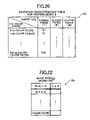
- FIG. 20 is an explanatory diagram showing another excitation characteristic storage unit storing excitation characteristics tables in the color converting apparatus of the third embodiment
- FIG. 21 is an explanatory diagram showing a two-dimensional excitation characteristics table stored in the excitation characteristics table of FIG. 20 ;
- FIG. 22 is an explanatory diagram showing an input profile saving unit according to the third embodiment.
- FIG. 23 is a flowchart illustrating the operations that the profile maker performs to create an input profile in the color converting apparatus of the third embodiment
- FIG. 24 is a flowchart illustrating the color conversion operations performed by the color management system in the color converting apparatus of the third embodiment
- FIG. 25 is an explanatory diagram showing a two-dimensional excitation characteristics table created in a modification of the third embodiment.
- FIG. 26 is an explanatory diagram showing a preferable one-dimensional reflectance table stored in the excitation characteristics table in the modification of the third embodiment.
- FIG. 1 shows a color converting apparatus 1 according to the preferred embodiment.
- the color converting apparatus 1 is connected to a monitor 2 and an inkjet printer 3 , and is designed to reproduce colors displayed on the monitor 2 with the inkjet printer 3 .
- the monitor 2 displays colors based on original data (Rin, Gin, Bin), wherein data Rin, Gin, and Bin included in the original data indicate gradations of the three primary colors.
- the color converting apparatus 1 converts the original data (Rin, Gin, Bin) into corrected data (Cout, Mout, Yout, Kout).
- the inkjet printer 3 creates an output image based on the corrected data (Cout, Mout, Yout, Kout).
- the color converting apparatus 1 of the present embodiment includes a personal computer.
- the color converting apparatus 1 includes: a CPU 10 , a RAM 12 , a ROM 14 , a hard disk 16 , an input/output (I/O) interface 18 , and a buffer memory 20 .
- a bus 22 connects the CPU 10 , RAM 12 , ROM 14 , hard disk 16 , I/O interface 18 , and buffer memory 20 to one another.
- the I/O interface 18 is connected also to an input device 24 , such as a keyboard and a mouse, a floppy disk drive 26 (“floppy” is a registered trademark), and a CD-ROM drive 28 , as well as the monitor 2 and inkjet printer 3 .
- the I/O interface 18 is further connected to a network 30 of an arbitrary type. When necessary, the I/O interface 18 can be connected also to a digital camera 4 and a scanner 5 .
- the ROM 14 previously stores therein: a program for the color management system CM and a program for a profile maker PM. These programs may also be stored in the hard disk 16 instead of the ROM 14 . It is noted that data of the programs of the color management system CM and the profile maker PM may be originally stored on a computer-readable recording medium, such as a floppy disk or a CD-ROM, and may be installed into the hard disk 16 via the floppy disk drive 26 or the CD-ROM drive 28 . Alternatively, data of the programs of the color management system CM and the profile maker PM may be downloaded from the network 30 such as the Internet or the like. The ROM 14 may previously store therein an application program. The application program functions to create desired images.
- the ROM 14 is formed with: a print data storage unit 14 a , an input profile storage unit 14 b , an excitation characteristic storage unit 14 c , and a spectral radiation (illumination) characteristic storage unit 14 d . These memory areas may be formed on the hard disk 16 rather than the ROM 14 .
- the buffer memory 20 functions as an input unit 20 a (see FIG. 6 ) for receiving original data (Rin, Gin, Bin) from the application program, and for temporarily saving that data.
- the buffer memory 20 also functions as an output unit 20 b (see FIG. 6 ) for receiving corrected data (Cout, Mout, Yout, Kout) from a color management system CM, described later, temporarily storing the corrected data, and outputting this data to the inkjet printer 3 via the I/O interface 18 thereafter.
- the CPU 10 executes the program for the profile maker PM, stored in the ROM 14 or the hard disk 16 , to create an output profile.
- the CPU 10 further executes the program for the color management system CM, stored in the ROM 14 or the hard disk 16 , to convert original data (Rin, Gin, Bin) into corrected data (Cout, Mout, Yout, Kout).
- the CPU 10 also controls overall operations of the color converting apparatus 1 .
- the CPU 10 executes the application program.
- the RAM 12 is for saving data, which is created by the CPU 10 when the CPU 10 performs calculations while executing the various programs.
- the RAM 12 is formed with: an output profile saving unit 12 a , a reference white data saving unit 12 b , a spectral reflection data saving unit 12 c , and a calorimetric measurement data saving unit 12 d .
- the output profile saving unit 12 a is for saving an output profile which are created by the CPU 10 while the CPU 10 executes the profile maker PM program.
- the reference white data saving unit 12 b , the spectral reflection data saving unit 12 c , and the calorimetric measurement data saving unit 12 d are for saving reference white color data, spectral reflectance data, and calorimetric measurement data, respectively, all of which are created by the CPU 10 while the CPU 10 executes the profile maker PM program.
- the input device 24 enables the user to input various instructions and data. As will be described later, the input device 24 functions as an environment light characteristic input unit 24 a and a paper type selecting unit 24 b (see FIG. 6 ).
- the environment light characteristic input unit 24 a is for inputting types of light sources to indicate the environment, in which colors outputted by the inkjet printer 3 will be observed.
- the paper type selecting unit 24 b is for selecting a type of paper, onto which the inkjet printer 3 outputs an image.
- Print data is prestored in the print data storage unit 14 a . This print data is used by the CPU 10 when the CPU 10 executes the profile maker PM program to create an output profile.
- the print data storage unit 14 a stores 754 sets of control signals (C, M, Y, K) as print data for designating 754 colors i (O ⁇ i ⁇ 753).
- the 754 sets of control signals (C, M, Y, K) are constructed from: 216 sets of control signals (C, M, Y, K), in which CMY have the values of 0, 10, 20, 40, 70, or 100% and K have a value of 0%; 216 sets of control signals (C, M, Y, K), in which CMY have values of 0, 10, 20, 40, 70, or 100% and K has a value of 20%; 125 sets of control signals (C, M, Y, K), in which CMY have the values of 0, 20, 40, 70, or 100% and K has the value of 40%; 125 sets of control signals (C, M, Y, K), in which CMY have the values of 0, 20, 40, 70, or 100% and K has the value of 60%; 64 sets of control signals (C, M, Y, K), in which CM
- the input profile storage unit 14 b prestores therein an input profile.
- the input profile is profile data for the monitor 2 , and is required for converting the original data (Rin, Gin, Bin) into device-independent Lab data (Lin, ain, bin).
- the color management system CM In order to convert a set of original data (Rin, Gin, Bin) into a set of Lab data (Lin, ain, bin), the color management system CM first determines a set of luminance values (Sr, Sg, Sb) for the three primary colors indicated by the original data set (Rin, Gin, Bin).
- the color management system CM determines a set of XYZ values (Xin, Yin, Zin), and subsequently determines a set of Lab data (Lin, ain, bin) based on the XYZ value set (Xin, Yin, Zin).
- the input profile storage unit 14 b prestores: gamma values ⁇ r, ⁇ g, ⁇ b; XYZ values Xr, Yr, Zr for R (red) light on the monitor 2 ; XYZ values Xg, Yg, Zg for G (green) light on the monitor 2 ; and XYZ values Xb, Yb, and Zb for B (blue) light on the monitor 2 ; XYZ values Xn, Yn, Zn for a prescribed reference white color.
- the gamma values ⁇ r, ⁇ g, and ⁇ b are determined by measuring the monitor 2 in advance.
- the XYZ values Xr, Yr, Zr, Xg, Yg, Zg, Xb, Yb, Zb are determined also by measuring the monitor 2 in advance.
- the excitation characteristic storage unit 14 c prestores a table of excitation characteristics as shown in FIG. 3 .
- the excitation characteristics table of FIG. 3 stores therein 754 two-dimensional excitation characteristics tables Ti (where 0 ⁇ i ⁇ 753) for each of three types of paper which can be used by the inkjet printer 3 .
- the three paper types include: normal paper (type I), glossy paper (type II), and coated paper (type III).
- each two-dimensional excitation characteristics table Ti contains a plurality of sets of excitation-reflectance data Bi ( ⁇ 0 , ⁇ ).
- the plurality of sets of excitation-reflectance data Bi ( ⁇ 0 , ⁇ ) are arranged in a two-dimensional matrix form in correspondence with combinations of a plurality of incident light wavelengths ⁇ and a plurality of reflected light wavelengths ⁇ 0 .
- the plurality of incident light wavelengths ⁇ are set at 10-nm intervals across the entire wavelength range of incident light (from 300 nm to 780 nm). In other words, the plurality of incident light wavelengths ⁇ are 300, 310, 320, . . .
- the plurality of reflected light wavelengths ⁇ 0 are set at 10-nm intervals across the entire wavelength range of reflected light (from 380 nm to 780 nm). In other words, the plurality of reflected light wavelengths ⁇ 0 are 380, 390, 400, . . . , and 780 nm.
- Each excitation-reflectance data set Bi ( ⁇ 0 , ⁇ ) is defined to indicate that when light with the incident light wavelength ⁇ falls incident on an object color that is produced by some control signal i, the object color reflects light with the reflected light wavelength ⁇ 0 at a ratio Bi ( ⁇ 0 , ⁇ ) indicative of the amount of the reflected light with respect to the amount of the incident light.
- the 754 two-dimensional excitation characteristics tables T 0 -T 753 are prepared for each type of paper in a manner as described below.
- one type of paper is loaded in the inkjet printer 3 .
- 754 color patches are created on the paper based on the 754 sets of print data (C, M, Y, K), indicating 754 colors i (0 ⁇ i ⁇ 753), stored in the print data storage unit 14 a.
- a two-dimensional excitation characteristics table Ti is created for the color patch of each color i, where 0 ⁇ i ⁇ 753, by performing the following spectral measurement.
- a monochromatic light having a wavelength ⁇ of 300 nm is irradiated on one color patch i.
- the spectrophotometer CM-3800d product name manufactured by Minolta and Nisshin Boseki can be used as the spectral sensor.
- a monochromatic light having another wavelength ⁇ of 310 nm is radiated on the same color patch i.
- a single color wavelength across the entire wavelength range of incident light 300 nm to 780 nm is irradiated in order progressively in intervals of 10 nm on a color patch of the single color i.
- a plurality of sets of excitation-reflectance data Bi ( ⁇ 0 , ⁇ ), for the combinations of the plurality of incident light wavelengths ⁇ and the plurality of reflected light wavelengths ⁇ 0 , are determined in the form of a two-dimensional matrix, as shown in FIG. 4 .
- This two-dimensional matrix is set as the two-dimensional excitation characteristics table Ti.
- 754 color patches are created for each of other paper types, and the above-described spectral methods are performed for each of the color patches, thereby creating 754 two-dimensional excitation characteristics tables T 0 -T 753 for each of the other paper types.
- the excitation characteristics table of FIG. 3 is created by arranging the two-dimensional excitation characteristics tables T 0 -T 753 for all paper types, as shown in FIG. 3 , and is stored in the excitation characteristic storage unit 14 c.
- a user will select one paper type from among the types I, II, and III, stored in the excitation characteristic storage unit 14 c , and input data of this type into the input device 24 (paper type selecting unit 24 b ) as the paper type to be used by the inkjet printer 3 .
- the spectral radiation characteristic storage unit 14 d prestores therein a spectral radiation characteristics table, such as that shown in FIG. 5 .
- the spectral radiation characteristics table holds data of a plurality of environment light characteristics in which an image outputted by the inkjet printer 3 can be observed.
- the spectral radiation characteristics table contains a one-dimensional environment light characteristics data array D for each of a plurality of light source types.
- the plurality of light source types include: an A light source (type I), a D65 light source (type II), and a xenon light source (type III),
- Each environment light characteristics data array D is a relative spectral power distribution, and includes a plurality of sets of relative spectral radiation characteristics data S( ⁇ ) in correspondence with a plurality of incident light wavelengths ⁇ ( 300 , 310 , 320 , . . . , 780 nm), which are set at intervals of 10 nm across the entire incident light wavelength range from 300 nm to 780 nm.
- Each data set S( ⁇ ) denotes the proportion at which the light source irradiates incident light of the wavelength ⁇ .
- each data set S( ⁇ ) is indicative of an amount of power of light with the incident light wavelengths ⁇ relative to an amount of power of light with 560 nm.
- each environment light characteristics data array D holds a plurality of relative spectral radiation characteristics data sets S( ⁇ ) for the same incident light wavelength range (300-780 nm) as that for the incident light wavelength ⁇ in the two-dimensional excitation characteristics tables Ti of FIG. 4 . It is noted that the environment light characteristics data array D has to hold data S( ⁇ ) for at least a wavelength covering the entire range of the incident light wavelengths ⁇ possessed by the two-dimensional excitation characteristics tables Ti. The environment light characteristics data array D may hold data S( ⁇ ) for additional wavelength ranges that exceed the 300-780 nm wavelength range of the incident light wavelengths ⁇ of the tables Ti.
- the user will select one of the light source types I, II, and III stored in the spectral radiation characteristic storage unit 14 d
- the user will input the selection information into the input device 24 (environment light characteristic input unit 24 a ) as the light source used for the environment in which an output image created by the inkjet printer 3 will be observed.
- the profile maker PM includes: a white color calculating unit 110 , a spectral reflection data calculating unit 120 , a color value computing unit 130 , and a profile creating unit 140 .
- the white color calculating unit 110 functions to read a single environment light characteristics data array D from the spectral radiation characteristic storage unit 14 d ( FIG. 5 ) in correspondence with the light source type (type I, II, or III) that is inputted into the environment light characteristic input unit 24 a by the user.
- the white color calculating unit 110 then calculates reference white data Xn, Yn, and Zn (tristimulus values of a perfectly diffuse surface) based on the data array D.
- the white color calculating unit 110 calculates the following Equation (7), using the plurality of sets of data S( ⁇ ) forming the data array D, to determine the tristimulus values Xn, Yn, and Zn for a perfectly diffuse surface.
- the white color calculating unit 110 stores these values Xn, Yn, and Zn in the reference white data saving unit 12 b .
- x( ⁇ ), y( ⁇ ), and z( ⁇ ) are color matching functions, which are defined in Table 2.1 of CIE (Commission Internationale de l'Eclairage) 15.2 (appended table 1 of JIS Z8701) and whose values are set to 0 for wavelengths below 380 nm.
- K is defined by the following Equation (8):
- Equations (7) and (8) it can be understood that Yn is always 100.
- the spectral reflection data calculating unit 120 functions also to read a single environment light characteristics data array D from the spectral radiation characteristic storage unit 14 d in correspondence with the light source type (type I, II, or III), which is inputted into the environment light characteristic input unit 24 a by the user.
- the spectral reflection data calculating unit 120 also reads 754 two-dimensional excitation characteristics tables T 0 -T 753 from the excitation characteristic storage unit 14 c in correspondence with the paper type (type I, II, or III), which is inputted into the paper type selecting unit 24 b by the user.
- the plurality of data sets Ri( ⁇ 0 ) are defined for the plurality of reflected light wavelengths ⁇ 0 , which are defined at intervals 10 nm within the range of 380-780 nm.
- the calculating unit 120 determines one set of spectral reflection characteristics data Ri( ⁇ 0 ) for the corresponding wavelength ⁇ 0 .
- the color value computing unit 130 first determines a set of XYZ values (Xi; Yi, Zi) for each color i using the following equation (10):
- the computing unit 130 integrates the product of the spectral reflection characteristic value Ri( ⁇ 0 ) and the color matching function (x( ⁇ 0 ), y( ⁇ 0 ), or z( ⁇ 0 )) with respect to the reflected light wavelengths ⁇ 0 at 10-nm intervals in the range of 380-780 nm, thereby determining the XYZ value Xi, Yi, or Zi.
- the computing unit 130 determines a set of Lab values (L*, a*, b*) for each color i by calculating the following equation (11) based on the set of XYZ values (Xi, Yi, Zi).
- L * 116*( Yi/Yn ) (1/3) ⁇ 16
- a * 500* ⁇ ( Xi/Xn ) (1/3) ⁇ ( Yi/Yn ) (1/3) ⁇
- b * 200* ⁇ ( Yi/Yn ) (1/3) ⁇ ( Zi/Zn ) (1/3) ⁇ (11)
- the computing unit 130 first resets the values Xn, Yn, and Zn, to be used for the calculation of equation (11) for the 0 th color, into the values X 0 ,Y 0 , and Z 0 , respectively.
- the computing unit 130 does not execute the resetting operation for the values Xn, Yn, and Zn, but uses the values Xn, Yn, and Zn as they are read from the reference white data saving unit 12 b.
- the color value computing unit 130 After computing the Lab value sets (L*, a*, b*) for all the 754 colors i (0 ⁇ i ⁇ 753), the color value computing unit 130 saves these Lab values in the calorimetric measurements data saving unit 12 d , as shown in FIG. 8 . In this way, the relationship between the CMYK values (C, M, Y, K) for the 754 colors and the Lab values (L, a, b) is determined by the computing unit 130 , and stored in the saving unit 12 d.
- Equation (1) the value of Y is determined by Equation (1)
- the value of L is determined by Equation (2). Because of the equations (1) and (3), Yn is always 100.
- the value B( ⁇ ) is defined as the spectral reflectance of an object color, and therefore satisfies the relationship of 0 ⁇ B( ⁇ ) ⁇ 1. Accordingly, the value Y is always less than or equal to Yn (100), and the value of L is always less than or equal to 100.
- the upper limit of 100 can be defined for the values Y and L*. A limiting process can be executed to determine that an error occurs when Y and L* are determined to exceed 100, then to rematch these values to 100.
- the excitation characteristics value Bi ( ⁇ 0 , ⁇ ) used in the present embodiment itself is a value between 0 and 1.
- the spectral reflection characteristic value Ri( ⁇ 0 ) is the result of taking the integral of the excitation characteristics values Bi ( ⁇ 0 , ⁇ ) over the entire incident light wavelength range. According to Equation (9), the value Ri( ⁇ 0 ) will be always greater than or equal to 0, but can also exceed 1 to indicate excitation. Accordingly, as is clear by Equations (7) and (10), the value Yi can exceed the value Yn, and the value of L* can exceed 100.
- the color value computing unit 130 does not determine that an error occurs even when the value Yi exceeds the Yn. In other words, the color value computing unit 130 does not execute the above-mentioned limiting process. Additionally, the work area in the RAM 12 for temporarily storing results of calculations is configured to be able to store values of Y that exceed Yn, that is, 100. Similarly, the calorimetric measurements data saving unit 12 d is configured to store a value for L greater than 100.
- the present embodiment is established to taking into account that the brightness of reflection light resulting from excitation can be greater than that of the incident light depending on the value of the spectral reflection characteristic data Ri( ⁇ 0 ).
- excitation is taken into account, enabling the values of Y and L* to exceed 100.
- the limiting process is eliminated in the present embodiment, allowing the value for L* to exceed 100.
- the data retaining range is allocated for the data retaining portion (work area in RAM 12 ) such that the value of Y can be accurately retained even when Y is calculated as a value exceeding Yn and that the value of L* can be accurately retained even when L* exceeds 100.
- the process will not generate an overflow error.
- the profile creating unit 140 functions to calculate an output profile based on a correlation between: print data (C, M, Y, K) of 754 colors i (0 ⁇ i ⁇ 753), stored in the print data storage unit 14 a , and Lab color values (L, a, b) for 754 colors, that are now stored in the calorimetric measurements data saving unit 12 d .
- the profile creating unit 140 stores the output profile in the output profile saving unit 12 a.
- the profile creating unit 140 first determines 101 4 sets of CMYK print data (C, M, Y, K) for all the 101 4 colors that include the 754 sets of print data (C, M, Y, K) for 754 colors. The profile creating unit 140 then determines a correlation between CMYK print data and Lab values.
- the profile creating unit 140 repeats this calculation until all the 101 4 sets of Lab values (L, a, b) are determined for all the 101 4 sets of print data (C, M, Y, K). In this way, Lab value sets are determined for all print data sets (C, X, Y, K). As a result, a relationship between (C, M, Y, K) and (L, a, b) is determined. This relationship will be referred to as “(C, M, Y, K)-(L, a, b) relationships” hereinafter.
- the profile creating unit 140 determines the reverse correlation of (L, a, b) and (C, M, Y, K) based on the (C, M, Y, K)-(L, a, b) relationship.
- the reverse correlation of (L, a, b) and (C, M, Y, K) will be referred to as “(L, a, b)-(C, M, Y, K) relationship” hereinafter.
- the profile creating unit 140 first defines the Lab space in which the L-axis, a-axis, and b-axis are orthogonal to one another.
- the profile creating unit 140 then defines a plurality of lattice points (L, a, b) by three-dimensionally dividing the Lab space into arbitrary equal intervals.
- the profile creating unit 140 selects, for each lattice point (L, a, b), one set of (L, a, b) among all the sets of Lab data (L, a, b) listed in the (C, M, Y, K)-(L, a, b) relationship.
- the profile creating unit 140 selects the one set of (L, a, b) that has the minimum color distance (color difference) from the subject lattice point (L, a, b) in the Lab space.
- the profile creating unit 140 then reads one set, of CMYK data (C, M, Y, K) that corresponds to the selected Lab data set (L, a, b) from the (C, M, Y, K)-(L, a, b) relationship, and stores this CMYK data in correspondence with the lattice point (L, a, b).
- the (L, a, b)-(C, M, Y, K) relationship is created in the form of a three-dimensional lookup table.
- the profile creating unit 140 stores this three-dimensional lookup table as the output profile in the output profile saving unit 12 a as shown in FIG. 9 .
- the color management system CM converts each set of original data (Rin, Gin, Bin), inputted into the buffer memory 20 (input unit 20 a ), into a set of Lab data (Lin, ain, bin) based on the input profile stored in the input profile storage unit 14 b .
- the color management system CM subsequently converts the Lab data set (Lin, ain, bin) into a set of corrected data (Cout, Mout, Yout, Kout) based on the output profile which is now stored in the output profile saving unit 12 a .
- the color management system CM outputs the corrected data set (Cout, Mout, Yout, Kout) to the inkjet printer 3 via the buffer memory 20 (output unit 20 b ).
- the color management system CM converts this data to a device-independent Lab data set (Lin, ain, bin).
- the color management system CM converts the data by performing the above Equations (4)-(6) based on the input profile.
- the color management system CM converts the Lab data set (Lin, ain, bin) into a corrected data set (Cout, Mout, Yout, Kout) using the output profile ( FIG. 9 ). More specifically, the color management system CM first finds out, in the Lab space, several Lab lattice points (eight lattice points, for example) that surround an input color point that is specified by the Lab data set (Lin, ain, bin). The color management system CM then searches for several sets of CMYK data (C, M, Y, K) that correspond to the several sets of Lab data (L, a, b) at the several Lab lattice points from the output profile.
- CMYK data C, M, Y, K
- the color management system Cm determines the corrected data set (Cout, Mout, Yout, Kout) corresponding to the inputted Lab data set (Lin, ain, bin) by performing an interpolation calculation based on the several CMYK data sets (C, M, Y, K) searched as described above. Details of this interpolation method is disclosed in the U.S. Pat. No. 5,835,624.
- the color management system CM outputs the corrected data (Cout, Mout, Yout, Kout) to the inkjet printer 3 via the buffer memory 20 .
- the user loads paper of the paper type inputted into the paper type selecting unit 24 b (one of types I, II, or III of FIG. 3 ) into the inkjet printer 3 .
- the inkjet printer 3 outputs an output image through a printing process based on the corrected data (Cout, Mout, Yout, Rout) on the paper of the selected paper type.
- the user views the outputted image under the light source type (one of types I, II, III of FIG. 5 ) that the user has inputted into the environment light characteristic input unit 24 a . In this way, the user can observe the output image at the same colors as those displayed by the monitor 2 based on the original data (Rin, Gin, Bin).
- a user operates the color converting apparatus 1 to create image data (Rin, Gin, Bin) to be displayed on the monitor 2 by using an image-creating application program.
- image data Rosin, Gin, Bin
- the user inputs his/her command to start up the profile maker PM.
- the profile maker PM stores the image data (Rin, Gin, Bin) created by the user in the buffer memory 20 .
- the CPU 10 controls the monitor 2 in S 10 to display names of all the light source types (in this example, an A light source, D 65 light source, and xenon light source set as types I, II, and III, respectively) stored in the, spectral radiation characteristics table ( FIG. 5 ) in the spectral radiation characteristic storage unit 14 d .
- the user is prompted to select one of the displayed light source types.
- the user By manipulating the input device 24 , the user selects a light source type that is used in the environment in which the user will view the printed image. For example, the user aligns the cursor with the name of a desired light source on the monitor 2 and clicks the mouse button to select the light source type. In this way, operation of the color converting apparatus 1 is extremely simple, since the user need only select a desired light source.
- the CPU 10 reads a single environment light characteristics data array D, which corresponds to the selected light source type, from the spectral radiation characteristics table ( FIG. 5 ) in the spectral radiation characteristic storage unit 14 d .
- the CPU 10 stores the environment light characteristics data array D in a work area (not shown) of the RAM 12 .
- the CPU 10 calculates the tristimulus values Xn, Yn, and Zn for a perfectly diffuse surface according to Equations (7) and (8) using a plurality of sets of relative spectral radiation characteristics data S( ⁇ ) that form the environment light characteristics data array D, which is read in S 20
- the CPU 10 stores the tristimulus values Xn, Yn and Zn in the reference white data saving unit 12 b of the RAM 12 .
- the CPU 10 controls the monitor 2 to display the names of all paper types (in the present embodiment, normal paper, glossy paper, and coated paper set to types I, II, and III, respectively) stored in the excitation characteristics table ( FIG. 3 ) of the excitation characteristic storage unit 14 c .
- the CPU 10 prompts the user to select a single type of paper.
- the user selects a desired type of paper. That is, the user aligns the cursor with a desired name of paper type on the monitor 2 and clicks the mouse button to select the paper type.
- the CPU 10 reads the 754 two-dimensional excitation characteristics tables T 0 -T 753 corresponding to the selected paper type from the excitation characteristics table ( FIG. 3 ) in the excitation characteristic storage unit 14 c , and stores the data in a work area of the RAM 12 .
- Equation (9) by calculating Equation (9) using: the plurality of sets of excitation-reflectance data Bi ( ⁇ 0 , ⁇ ) in the corresponding two-dimensional excitation characteristics table Ti (0 ⁇ i ⁇ 753) that has been stored in the work area of the RAM 12 in S 50 ; and the plurality of sets of relative spectral radiation characteristics data S( ⁇ ) making up the environment light characteristics data array D that has been stored in the work area of the RAM 12 in S 20 .
- the CPU 10 determines an XYZ value set (Xi, Yi, Zi) for each color i (0 ⁇ i ⁇ 753) by calculating Equation (10) based on the values Xn, Yn, and Zn that have been stored in the reference white data saving unit lib in S 30 and the spectral reflection characteristic data Ri( ⁇ 0 ) (0 ⁇ i ⁇ 753) that has been stored in the spectral reflection data saving unit 12 c in S 60 .
- the CPU 10 further determines an Lab value set (L*, a*, b*) for each color i (0 ⁇ i ⁇ 753) by calculating Equation (11) based on the XYZ value set (X, Y, Z).
- the CPU 10 saves the Lab data sets (L, a, b) calculated in S 70 for all the 754 colors as calorimetric measurements data in the calorimetric measurements data saving unit 12 d.
- the CPU 10 determines the (C, M, Y, K)-(L, a, b) relationships (that is, correlations between 101 4 CMYK print data sets and Lab data sets) based on the relationships between the 754 sets of CMYK print data (C, M, Y, K) for 754 colors, which are stored in the print data storage unit 14 a , and the 754 sets of Lab data (L, a, b) for the 754 colors, which have been stored in the calorimetric measurements data saving unit 12 d in S 80 .
- the CPU 10 performs an inverse calculation based on the (C, M, Y, K)-(L, a, b) relationships determined in S 90 , to determine the (L, a, b)-(C, M, Y, K) relationships.
- the CPU 10 stores the three-dimensional lookup table showing the (L, a, b)-(C, M, Y, K) relationships in the output profile saving unit 12 a as an output profile.
- the user After the profile maker PM completes its process in this way, the user starts up the color management system CM program and issues an instruction to perform a print operation.
- the CPU 10 After the color management system CM starts up, as shown in the flowchart of FIG. 11 , the CPU 10 reads each set of original data (Kin, Gin, Bin) from the buffer memory 20 in S 200 .
- the CPU 10 determines one set of Lab data (Lin, ain, bin) for each set of original data (Rin, Gin, Bin) based on the input profile stored in the input profile storage unit 14 b . To do this, the CPU 10 calculates the above Equations (4)-(6) based on each set of original data (Rin, Gin, Bin).
- the CPU 10 converts each set of Lab data (Lin, ain, bin) to a set of corrected data (Cout, Mout, Yout, Kout) by performing interpolation calculation using the output profile now stored in the output profile saving unit 12 a.
- the CPU 10 outputs the corrected data (Cout, Mout, Yout, Kout) to the inkjet printer 3 via the buffer memory 20 .
- the color management system CM process is completed after all the sets of original data (Rin, Gin, Bin) are converted to corrected data (Cout, Mout, Yout, Kout) and outputted.
- the inkjet printer 3 produces an output image by performing a printing operation on paper of the paper type selected by the user based on the corrected data (Cout, Mout, Yout, Kout).
- the color converting apparatus 1 of the present embodiment converts image data (Rin, Gin, Bin) to Lab data (Lin, ain, bin) based on the input profile.
- the color converting apparatus 1 further converts the Lab data (Lin, ain, bin) to corrected data (Cout, Mout, Yout, Kout) based on the output profile.
- the output profile has been created by calculating Equations (9)-(11) based on: the excitation-reflectance data Bi ( ⁇ 0 , ⁇ ) in the two-dimensional excitation characteristics tables Ti that correspond to the paper type used in the inkjet printer 3 ; and the relative spectral radiation characteristics data S( ⁇ ) for the light source type used when viewing the outputted image. Accordingly, output images created using corrected data (Cout, Mout, Yout, Kout) will have the same colors as those displayed in the monitor 2 when observed in the observation environment of the light source type selected by the user, even when the created image includes a fluorescent light component.
- the original data (Rin, Gin, Bin) is created by the application program on the color converting apparatus 1 to produce images for the monitor 2 .
- the original data (Rin, Gin, Bin) is temporarily stored in the buffer memory 20 before being subjected to color conversion.
- this original data (Rin, Gin, Bin) may not be created by the color converting apparatus 1 , but can be prestored on a storage medium, such as a floppy disk or a CD-ROM.
- the original data (Rin, Gin, Bin) will be read by the floppy disk drive 26 or the CD-ROM drive 28 and temporarily stored in the buffer memory 20 via the I/O interface 18 for color conversion. It is also possible to perform color conversion after inputting the original data (Rin, Gin, Bin) for the monitor 2 via the I/O interface 18 from the network 30 and temporarily storing the data in the buffer memory 20 .
- a plurality of two-dimensional excitation characteristics tables Ti are provided in one to one correspondence with a plurality of colors i.
- the excitation characteristics table Ti for each color i contains a plurality of sets of excitation-reflectance data Bi ( ⁇ 0 , ⁇ ) in a two-dimensional matrix form, for a plurality of combinations of incident light wavelengths ⁇ and reflected light wavelengths ⁇ 0 .
- the excitation-reflectance data Bi ( ⁇ 0 , ⁇ ) indicate the ratio of the amount of the reflected light wavelength ⁇ 0 generated in response to incidence of the incident light wavelength ⁇ , with respect to the amount of the incident light wavelength ⁇ .
- Equations (9)-(11) are calculated to create an output profile, and color conversion is performed by using the output profile.
- the two-dimensional excitation characteristics table Ti ( FIG. 4 ) includes not only the excitation-reflectance data Bi ( ⁇ 0 , ⁇ ) for incident light wavelengths ⁇ in the visible range from 400-780 nm, but also the excitation-reflectance data Bi ( ⁇ 0 , ⁇ ) for incident light wavelengths ⁇ in the ultraviolet range smaller than 400 nm.
- each excitation-reflectance data set Bi ( ⁇ 0 , ⁇ ) is in the form of a two-dimensional data for two wavelengths (reflected wavelength ⁇ 0 and incident light wavelength ⁇ ) and therefore can contain information on excitation for generating a reflected light wavelength ⁇ 0 different from the incident light wavelength ⁇ . It is sufficient that the two-dimensional excitation characteristics table Ti be configured to list up the plurality of excitation-reflectance data sets (excitation characteristics data sets) Bi ( ⁇ 0 , ⁇ ) for the two wavelengths ⁇ 0 and ⁇ . It is unnecessary that the two-dimensional excitation characteristics table Ti contains the ultraviolet range in the incident light wavelength ⁇ .
- the two-dimensional excitation characteristics table Ti may be configured from the excitation characteristics data Bi ( ⁇ 0 , ⁇ ) for incident light wavelengths ⁇ in the visible range from 400-780 nm and for reflected light wavelengths ⁇ 0 in the visible range from 400-780 nm.
- Papers such as normal paper, glossy paper, and coated paper, reproduce colors by generating a reflected light in response to incident light.
- paper types include transparencies for use on overhead projectors.
- the excitation characteristic storage unit 14 c may be prestored with store 754 two-dimensional excitation characteristics tables T 0 -T 753 for each paper type that generates transmitted light.
- the transmittance indicates a ratio of the amount of the transmitted light at a wavelength ⁇ 0 with respect to the amount of the incident light at a wavelength ⁇ .
- a two-dimensional excitation characteristics table Ti for each color i is created by arranging a plurality of excitation-transmittance data sets Bi ( ⁇ 0 , ⁇ ) two-dimensionally for combinations of a plurality of incident light wavelengths ⁇ and a plurality of transmitted light wavelengths ⁇ 0 .
- the user can select a type of light source that will illuminate the transparency when using the overhead projector.
- the user can select “transparency sheet” as the paper type.
- the values Ri( ⁇ 0 ) obtained in S 60 by Equation (9) for each color i are indicative of spectral transmission characteristics of the subject color i.
- the Lab values are calculated in S 70 according to Equations (10) and (11).
- 754 two-dimensional excitation characteristics tables T 0 -T 753 are stored in the excitation characteristic storage unit 14 c , as shown in FIG. 3 , in correspondence with each paper type that can be used in the inkjet printer 3 .
- the excitation characteristics vary not only according to types of paper, but also according to types of ink.
- each two-dimensional excitation characteristics table Ti (0 ⁇ i ⁇ 753, FIG. 4 ) is configured of a plurality of excitation characteristics data sets Bi ( ⁇ 0 , ⁇ ) for a plurality of incident light wavelengths ⁇ and reflected light wavelengths ⁇ 0 .
- Each data set Bi ( ⁇ 0 , ⁇ ) has been determined by producing a color patch by using a corresponding color control signal i and by using a corresponding paper type and a corresponding ink type.
- a reflectance (or transmittance) of the color patch is measured at a corresponding incident light wavelength ⁇ and at a corresponding reflected light wavelength ⁇ 0 .
- the user selects in S 40 of FIG. 10 both of the paper type and ink type to be used in the printing process.
- the CPU 10 can select the 754 two-dimensional excitation characteristics tables T 0 -T 753 in correspondence with the combination of the paper type and ink type selected by the user.
- original data (Rin, Gin, Bin) used to drive the monitor 2 is subjected to color conversion.
- original data (Rin, Gin, Bin) produced by other image data handling devices may be subjected to a color conversion process.
- original data (Rin, Gin, Bin) may be produced by the digital camera 4 or the scanner 5 shown in FIG. 1 and may be inputted into the color converting apparatus 1 for color conversion.
- the input profile storage unit 14 b is prestored with a three-dimensional lookup table as an input profile.
- the three-dimensional lookup table includes correlations between a plurality of RGB data sets (R, G, B) and a plurality of Lab data sets (L, a, b).
- the plurality of RGB data sets (R, G, B) are those that can be inputted from an input-end device (digital camera 4 , scanner 5 , or the like) to the color converting apparatus 1 .
- the three-dimensional lookup table is created in advance and stored in the input profile storage unit 14 b.
- the buffer memory 20 functions as the input unit 20 a (see FIG. 6 ) for receiving and temporarily storing original data (Rin, Gin, Bin) from the digital camera 4 or scanner 5 via the I/O interface 18 .
- the color management system CM calculates Lab data (Lin, ain, bin) in S 210 by performing an interpolation calculation using the three-dimensional lookup table in the input profile storage unit 14 b.
- the environment light characteristics data array D is stored in the spectral radiation characteristic storage unit 14 d for each of the plurality of light source types. Accordingly, the user selects a desired light source in S 10 of FIG. 10 . In S 20 , one environment light characteristics data array D is read from the spectral radiation characteristic storage unit 14 d for the selected light source type.
- the user produces a desired environment light characteristics data array D′, as shown in FIG. 12 .
- the data array D′ is indicative of spectral distribution of light illumination in a desired environment, in which the user will observe images created by the inkjet printer 3 .
- the data array D′ includes a plurality of sets of relative spectral radiation characteristics data S′( ⁇ ) for the plurality of wavelengths ⁇ (300, 310, 320 . . . , 780 nm) within the incident light wavelength range of 300-780 nm.
- the user uses a measuring instrument, such as a spectrophotometer, to actually measure the power of light with wavelength ⁇ in the desired environment.
- the process of the profile maker PM is modified as shown in FIG. 13 by omitting 520 in FIG. 10 and by providing the process of S 10 ′ in place of S 10 .
- the user inputs his/her desired environment light characteristics data array D′ into the color converting apparatus 1 . That is, the user inserts a floppy disk or a CD-R storing the prescribed data array D′ of FIG. 12 into the floppy disk drive 26 or the CD-ROM drive 28 .
- the CPU 10 drives the floppy disk drive 26 or CD-ROM drive 28 , reads the data array D′, and stores the data array D′ in a work area of the RAM 12 .
- the user can download the data array D′ from the network 30 into the work area of the RAM 12 .
- the floppy disk drive 26 , CD-ROM drive 28 , network 30 , or the like functions as the environment light characteristic input unit 24 a.
- the user can input an array of desired environment data indicating his/her desired output-end observation environment. Accordingly, it is possible to generate converted data that accurately reproduces a color specified by the input data under any desired environment.
- the user selects an observation environment (light source types I, II, or III in FIG. 5 ).
- the CPU 10 reads a corresponding environment light characteristics data array D from the spectral radiation characteristic storage unit 14 d .
- the user selects a paper type (type I, II, or III in FIG. 3 ).
- the CPU 10 reads corresponding 754 two-dimensional excitation characteristics tables Ti (0 ⁇ i ⁇ 753) from the excitation characteristic storage unit 14 c .
- the CPU 10 creates an output profile based on a plurality of relative spectral radiation characteristics data sets S( ⁇ ) forming the data array D and a plurality of excitation-reflectance data sets Bi ( ⁇ 0 , ⁇ ) forming each table Ti.
- the CPU 10 stores this output profile in the output profile saving unit 12 a.
- the ROM 14 is provided with an output profile storage unit 14 e , as indicated by the broken line in FIG. 2 .
- the output profile storage unit 14 e is prestored with nine output profiles in correspondence with nine combinations of the three light source types (types I, II, and III) and the three paper types (types I, II, and III) that can be selected by the user.
- Each output profile is a three-dimensional lookup table designating (L, a, b)-(C, M, Y, K) correlations, as is created in the first embodiment ( FIG. 9 ).
- These nine output profiles are created in advance for the combinations of light source types and paper types by executing the profile maker PM on another computer that is separate from the color converting apparatus 1 .
- operations of the profile maker PM ( FIG. 10 ) of the first embodiment are repeatedly executed on the separate computer.
- the light source type selected in S 10 and the paper type selected in S 40 are changed in sequence.
- the plurality of output profiles created in this way are stored in the output profile storage unit 14 e in the color converting apparatus 1 .
- the color converting apparatus 1 is prestored with all the output profiles that can be used in color conversion.
- the color converting apparatus 1 does not need to store a program for the profile maker PM. Accordingly, as shown in FIG. 15 , the color converting apparatus 1 of the present embodiment is no longer provided with the print data storage unit 14 a , spectral radiation characteristic storage unit 14 d , excitation characteristic storage unit 14 c , reference white data saving unit 12 b , spectral reflection data saving unit 12 c , and colorimetric measurements data saving unit 12 d , all of which are used to create the output profiles in the first embodiment.
- the color management system CM functions as shown in FIG. 15 . More specifically, the color management system CM converts the original data (Rin, Gin, Bin) in the buffer memory 20 into Lab data (Lin, ain, bin) based on the input profile. The color management system CM then selects a single output profile from the output profile storage unit 14 e ( FIG. 14 ) based on the combination of light source type that the user inputs into the environment light characteristic input unit 24 a and the paper type selected by the user with the paper type selecting unit 24 b . The color management system CM stores the output profile read from the output profile storage unit 14 e in the output profile saving unit 12 a .
- the color management system CM then converts the Lab data (Lin, ain, bin) into corrected data (Cout, Mout, Yout, Kout) based on the output profile now stored in the output profile saving unit 12 a .
- the color management system CM outputs the corrected data to the inkjet printer 3 via the buffer memory 20 (output portion 20 b ).
- the user When the user wishes to use the inkjet printer 3 to print image data (Rin, Gin, Bin) created and displayed on the monitor 2 , the user starts the color management system CM.
- the image data (Rin, Gin, Bin) is inputted into the buffer memory 20 .
- the CPU 10 controls the monitor 2 in S 150 of FIG. 16 to display names of the three light source types (A light source, D 65 light source, and xenon light source set as types I, II, and III, respectively) that correspond to all the nine output profiles stored in the output profile storage unit 14 e ( FIG. 14 ).
- the color management system CM then prompts the user to select a single light source type.
- the user manipulates the input device 24 to select a light source type that will be used in the environment in which the user views the outputted image.
- the CPU 10 controls the monitor 2 to display names of the three paper types (normal paper, glossy paper, and coated paper set as types I, II, and III, respectively) that correspond to all the nine output profiles stored in the output profile storage unit 14 e ( FIG. 14 ).
- the CPU 10 prompts the user to select a single paper type
- the user operates the input device 24 to select a desired paper type.
- the CPU 10 reads, from the output profile storage unit 14 e , a single output profile that corresponds to the combination of the light source selected in S 150 and the paper type selected in S 160 , and stores the output profile in the output profile saving unit 12 a.
- color conversion is performed by executing the processes of S 200 -S 230 similarly to the process ( FIG. 11 ) of the first embodiment.
- the entire color conversion operation can be performed extremely quickly, since an output profile corresponding to the combination of light source and paper type selected by the user can be simply selected.
- the selected output profile is created in advance by performing Equations (9)-(11) based on: the excitation-reflectance data Bi ( ⁇ 0 , ⁇ ) in the two-dimensional excitation characteristics tables Ti corresponding to the user-specified paper type, and the relative spectral radiation characteristics data S( ⁇ ) for the user's specified light source type.
- the output image will appear to have the same colors as that displayed on the monitor 2 when observed in an environment having the user's specified light source, even when the output image contains a fluorescent component.
- the print data storage unit 14 a , spectral radiation characteristic storage unit 14 d , excitation characteristic storage unit 14 c , reference white data saving unit 12 b , spectral reflection data saving unit 12 c , and calorimetric measurements data saving unit 12 d used to create the output profiles are omitted from the color converting apparatus 1 , as shown in FIG. 15 .
- the spectral radiation characteristic storage unit 14 d is retained in the color converting apparatus 1 , as shown in FIG. 17 .
- the spectral radiation characteristic storage unit 14 d is prestored with the environment light characteristics data arrays D for the three light source types I, II, and II, as shown in FIG. 5 .
- the floppy disk drive 26 , CD-ROM drive 28 , network 30 , or the like of the present modification functions as the environment light characteristic input unit 24 a for inputting the desired environment light characteristics data array D′ ( FIG. 12 ) that is created by the user through actual measurements.
- the color management system CM functions as shown in FIG. 17 .
- the color management system CM converts the original data (Rin, Gin, Bin) inputted into the buffer memory 20 into Lab data (Lin, ain, bin) based on the input profile.
- the color management system CM selects, from among the plurality of environment light characteristics data arrays D in the spectral radiation characteristic storage unit 14 d (see FIG. 5 ), one data array D that indicates the environment characteristics closest to the data array D′ that the user has inputted into the environment light characteristic input unit 24 a.
- the color management system CM determines, for each wavelength ⁇ (300, 310, 320, . . . , 780 nm) in the incident light wavelength range (300-780 nm), the difference between a data set S′( ⁇ ) in the inputted data array D′ ( FIG. 12 ) and a data set S( ⁇ ) in one data array D in the storage unit 14 d ( FIG. 5 ).
- the color management system CM calculates the total sum of differences by adding together the differences for all the wavelengths ⁇ of 300, 310, 320, . . . , 780 nm.
- the color management system CM performs the above-described calculation for each of all the three data arrays D stored in the storage unit 14 d ( FIG. 5 ). In this way, the color management system CM calculates., the total sum of differences between the desired data array D′ and a data array D for light source I; the total sum of differences between the desired data array D′ and a data array D for light source IT; and the total sum of differences between the desired data array D′ and a data array D for light source III.
- the color management system CM selects, as a data array that is closest to the data array D′, one data array D having the smallest total sum of differences among the three data arrays D.
- the color management system CM determines a light source type that corresponds to the selected data array D.
- the color management system CM reads, from the output profile storage unit 14 e ( FIG. 14 ), one output profile that corresponds to the combination of the selected light source type and the paper type selected by the user with the paper type selecting unit 24 b .
- the color management system CM stores the output profile in the output profile saving unit 12 a.
- the color management system CM then converts the Lab data (Lint ain, bin) to corrected data (Cout, Mout, Yout, Kout) based on the output profile now stored in the saving unit 12 a .
- the color management system CM outputs this corrected data to the inkjet printer 3 via the buffer memory 20 .
- the user inputs the user's desired environment light characteristics data array D′ into the color converting apparatus 1 . That is, the user inserts a floppy disk or a CD-R that stores the data array D′ into the floppy disk drive 26 or the CD-ROM drive 28 .
- the CPU 10 drives the floppy disk drive 26 or CD-ROM-drive 28 to store the data array D′ in a work area of the RAM 12 .
- the CPU 10 can download the data array D′ into the work area of the RAM 12 from the network 30 .
- the CPU 10 selects one environment light characteristics data array D that is closest to the inputted data array D′ from the spectral radiation characteristic storage unit 14 d ( FIG. 5 ), and determines a corresponding light source type.
- the CPU 10 prompts the user to select a paper type.
- the user selects a paper type.
- the CPU 10 reads from the output profile storage unit 14 e a single output profile that corresponds to the combination of the light source type selected in S 150 and the paper type selected in S 160 , and stores the output profile in the output profile saving unit 12 a Subsequently, steps S 200 -S 230 are executed to perform color conversion, in the same manner as described in the first embodiment.
- the color converting apparatus 1 of the present modification can perform extremely quick color conversion, since the apparatus need only select an output profile for one light source type the most similar to the environment characteristics inputted by the user.
- the output profile storage unit 14 e may be prestored with a plurality of output profiles corresponding to a combination of all ink types, all paper types, and all light source types by taking into account a plurality of ink types as in the third modification of the first embodiment.
- the user selects both a paper type and ink type in S 160 of FIG. 16 .
- the CPU 10 can select an output profile corresponding to a combination of the light source type selected by the user in S 150 and the paper type and ink type selected in S 160
- the color converting apparatus 1 functions to create on the inkjet printer 3 color samples of printed materials that are to be created using a printing device 6 shown by the broken line in FIG. 1 .
- the printing device 6 produces printed materials by using the original data (Cin, Min, Yin, Kin).
- the color converting apparatus 1 converts the original data (Cin, Min, Yin, Kin) into corrected data (Cout, Mout, Yout, Kout) so that the inkjet printer 3 will create the same colors as the printed materials by using the corrected data (Cout, Mout, Yout, Rout).
- the user can store original data (Cin, Min, Yin, Kin), to be inputted to the printing device 6 , on a data storing medium, such as a floppy disk or CD-R.
- a data storing medium such as a floppy disk or CD-R.
- the user inserts this floppy disk or CD-R into the floppy disk drive 26 or CD-ROM drive 28 of the color converting apparatus 1 ( FIG. 2 ).
- the original data (Cin, Min, Yin, Kin) is read and stored in the buffer memory 20 via the I/O interface 18 .
- the user can input the original data (Cin, Min, Yin, Kin) into the color converting apparatus 1 from the network 30 .
- This original data (Cin, Min, Yin, Kin) is read and stored in the buffer memory 20 via the I/O interface 18 .
- the buffer memory 20 functions as the input unit 20 a (see FIG. 19 ) for receiving the original data (Rin, Gin, Bin) via the I/O interface 18 from the floppy disk drive 26 , the CD-ROM drive 28 , or a type of network 30 .
- the buffer memory 20 temporarily stores the original data (Rin, Gin, Bin).
- the profile maker PM of the present embodiment not only creates an output profile, but also an input profile. Therefore, the ROM 14 is not provided with the input profile storage unit 14 b . Instead, the RAM 12 is provided with an input profile saving unit 12 e as indicated by the broken lines in FIG. 2 . The input profile is created by the profile maker PM, and then is stored in the input profile saving unit 12 e.
- excitation characteristic storage unit 14 c in addition to the excitation characteristic storage unit 14 c , another excitation characteristic storage unit 14 f is formed in the ROM 14 , as shown in FIG. 2 .
- 754 two-dimensional excitation characteristics tables T 0 ′-T 753 ′ are prestored in the excitation characteristic storage unit 14 f in correspondence with all paper types used by the printing device 6 (in the present embodiment, normal paper, glossy paper, and coated paper set as types I, II, and III, respectively).
- one two-dimensional excitation characteristics table Ti′ (0 ⁇ i ⁇ 753) corresponding to each paper type used in the printing device 6 contains a plurality of sets of excitation-reflectance data Bi ( ⁇ 0 , ⁇ ).
- the two-dimensional excitation characteristics table Ti′ (0 ⁇ i ⁇ 753) contains a plurality of data sets Bi ( ⁇ 0 , ⁇ ) in correspondence with combinations of a plurality of incident light wavelengths ⁇ and a plurality of reflected light wavelengths ⁇ 0 .
- the plurality of incident light wavelengths ⁇ are defined at 10-nm intervals within the incident light wavelength range of 300-780 nm, and the plurality of reflected light wavelengths ⁇ 0 are defined at 10-nm intervals within the reflected light wavelength range of 380-780 nm.
- the 754 two-dimensional excitation characteristics tables T 0 -T 753 ( FIG. 3 ) for the inkjet printer 3 are created in advance for each paper type used on the inkjet printer 3 . That is, the inkjet printer 3 is driven to produce 754 color patches on each corresponding paper type based on the 754 sets of print data (C, M, Y, K), and measurements are taken of these color patches. Similarly, the 754 two-dimensional excitation characteristics tables T 0 ′-T 753 ′ for the printing device 6 are created in advance for each paper type used on the printing device 6 .
- the tables T 0 ′-T 753 ′ for the printing device 6 are created according to the same method used to create the tables T 0 -T 753 for the inkjet printer 3 . That is, the inkjet printer 3 is driven to produce 754 color patches on each corresponding paper type based on the 754 sets of print data (C, M, Y, K), and measurements are taken of these color patches.
- the environment light characteristic input unit 24 a not only functions for inputting a type of light source indicating the environment in which color samples outputted by the inkjet printer 3 will be observed, but also functions for inputting a type of light source indicating the environment in which printed materials outputted by the printing device 6 will be observed.
- the paper type selecting unit 24 b not only functions for selecting a type of paper used on the inkjet printer 3 for outputting color samples, but also functions for selecting a type of paper used for outputting printed materials on the printing device 6 .
- the white color calculating unit 110 serves to create an output profile in the present embodiment.
- these components also function to create an input profile in the present embodiment, in a manner as described below.
- the white color calculating unit 110 functions to read, from the spectral radiation characteristic storage unit 14 d ( FIG. 5 ), a single environment light characteristics data array D that corresponds to the light source type (type I, II, or III) to be used when viewing printed materials created on the printing device 6 . It is noted that the light source type is designated at the environment light characteristic input unit 24 a by the user,.
- the white color calculating unit 110 calculates white reference values Xn, Yn, and Zn according to Equation (7) based on the relative spectral radiation characteristics data sets S( ⁇ ) in the data array D.
- the white reference values Xn, Yn, and Zn are saved in the reference white data saving unit 12 b.
- the spectral reflection data calculating unit 120 functions to read, from the spectral radiation characteristic storage unit 14 d , the single environment light characteristics array D that corresponds to the light source type (type I, II, or III) to be used when viewing printed materials created on the printing device 6 . It is noted that the light source type is inputted into the environment light characteristic input unit 24 a by the user.
- the spectral reflection data calculating unit 120 reads, from the other excitation characteristic storage unit 14 f ( FIG. 20 ), 754 two-dimensional excitation characteristics tables T 0 ′-T 753 ′ that correspond to the paper type (type I, II, or III) to be used in the printing device 6 . It is noted that the paper type is designated at the paper type selecting unit 24 b by the user.
- the spectral reflection characteristic values Ri( ⁇ 0 ) are saved in the spectral reflection data saving unit 12 c as shown in FIG. 7 .
- the Lab color values (L*, a*, b*) for the 754 colors are stored in the calorimetric measurement data saving unit 12 d.
- the profile creating unit 140 functions to create a correlation between all the 101 4 colors of CMYK print data and Lab data in the form of a four-dimensional lookup table. The correlation is established based on the relationship between print data (C, M, Y, K) of 754 colors i (0 ⁇ i ⁇ 753) stored in the print data storage unit 14 a and Lab color values (L*, a*, b*) for the 754 colors stored in the colorimetric measurements data saving unit 12 d .
- the profile creating unit 140 stores data of this correlation as an input profile in the input profile saving unit 12 e , as shown in FIG. 22 .
- the color converting apparatus 1 of the present embodiment has the same configuration as the color converting apparatus 1 in the first embodiment.
- the CPU 10 first creates an input profile according to substantially the same method used in the first embodiment to create the output profile.
- the CPU 10 prompts the user in S 310 to select a light source type for the environment in which printed material created on the printing device 6 will be observed, just as in step S 10 of the first embodiment ( FIG. 10 ).
- the environment light characteristics data array D of the selected light source type is read from the spectral radiation characteristic storage unit 14 d ( FIG. 5 ) and stored in a work area of the RAM 12 .
- Equation (7) is used to calculate the tristimulus values Xn, Yn, and Zn of a perfectly diffuse surface based on the plurality of data sets S( ⁇ ) forming the data array D of the selected light source type.
- the CPU 10 prompts the user to select a type of paper to be used by the printing device 6 .
- the CPU 10 reads the 754 two-dimensional excitation characteristics tables T 0 ′-T 753 ′ (Ti′ (0 ⁇ i ⁇ 753)) that correspond to the paper type selected by the user from the other excitation characteristic storage unit 14 f ( FIG. 20 ) and stores these tables Ti′ (0 ⁇ i ⁇ 753) in the work area of the RAM 12 .
- the CPU 10 uses Equation (9) to calculate the spectral reflection characteristic values Ri( ⁇ 0 ) based on the plurality of data sets Bi ( ⁇ 0 , ⁇ ) that make up the tables Ti′ (0 ⁇ i ⁇ 753)) now stored in the RAM 12 , and saves the result in the spectral reflection data saving unit 12 c as shown in FIG. 7 .
- the CPU 10 calculates the XYZ values (Xi, Yi, Zi) and the Lab values (L*, a*, b*) for each color i according to Equations (10) and (11) and stores the results in the colorimetric measurements data saving unit 12 d as shown in FIG. 8
- the CPU 10 calculates Lab value sets corresponding to all the 101 4 sets of CMYK data that include the 754 CMYK print data in the print data storage unit 14 a .
- the CPU 10 creates correlations between all the 101 4 CMYK data sets (C, X, Y, K) and the corresponding 101 4 Lab data sets (L, a, b) in the form of a 4-dimensional lookup table. Unlike the first embodiment, the reverse calculation of S 100 ( FIG. 10 ) is not executed in the present embodiment.
- the program proceeds directly from S 390 to S 410 .
- the CPU 10 stores, as an input profile, all the 101 4 CMYK data sets (C, M, Y, K) and their corresponding 101 4 Lab data sets (L, a, b) determined in S 390 in the colorimetric measurements data saving unit 12 d as shown in FIG. 22 .
- the CPU 10 creates an output profile according to the operations in the same manner as in the first embodiment ( FIG. 10 ).
- the user selects in S 10 the light source type that will be used in the environment in which the client will view the sample created by the inkjet printer 3 .
- the user selects a paper type that will be used for creating the sample on the inkjet printer 3 .
- the profile maker PM process ends, as in the first embodiment, and the color management system CM process is initiated.
- the CPU 10 reads in S 500 original data (Cin, Min, Yin, Kin) that has been inputted into the buffer memory 20 for output on the printing device 6 .
- the CPU 10 converts the original data (Cin, Min, Yin, Kin) to Lab data (Lin, ain, bin) based on the input profile stored in the calorimetric measurements data saving unit 12 d . More specifically, the original data (Cin, Min, Yin, Kin) is converted to Lab data (Lin, ain, bin) based on a correlation between the CMYK data and Lab data in the input profile ( FIG. 22 ).
- the inkjet printer 3 performs a printing process based on the corrected data (Cout, Mout, Yout, Kout) on a paper type selected in S 40 ( FIG. 10 ) to produce a sample.
- the client views the sample under a light source type selected in S 10 ( FIG. 10 )
- the color observed in this way will appear to be the same as the color on printed material to be printed by the printing device 6 on paper selected in S 340 ( FIG. 23 ) and observed under a light source selected in S 310 ( FIG. 23 ). Accordingly, the client can accurately determine the color state of the printed material to be printed by the printing device 6 by viewing the sample.
- the color converting apparatus 1 converts the original data (Cin, Min, Yin, Kin) to Lab data (Lin, ain, bin) based on the input profile.
- the input profile has been created by calculating Equations (9)-(11) based on: the excitation characteristics Bi ( ⁇ 0 , ⁇ ) for the two-dimensional excitation characteristics tables Ti′ corresponding to the paper type used on the printing device 6 , and the relative spectral radiation characteristics S( ⁇ ) for the light source used in the printed-material observation environment.
- the color converting apparatus 1 converts the Lab data (Lin, ain, bin) to corrected data (Cout, Mout, Yout, Kout) based on the output profile.
- the output profile has been created by calculating Equations (9)-(11) based on the excitation characteristics Bi ( ⁇ 0 , ⁇ ) for the two-dimensional excitation characteristics tables Ti corresponding to the paper type to be used on the inkjet printer 3 , and the relative spectral radiation characteristics S( ⁇ ) for the light source used in the sample observation environment. Accordingly, when a sample created according to the corrected data (Cout, Mout, Yout, Kout) is observed under the observation environment for the sample, the colors of the sample will appear the same as those observed on the final printed material under the observation environment for the final printed material, even when the sample and/or final printed material contains a fluorescent component.
- the output profile can be created in the present embodiment as in the fifth modification of first embodiment ( FIG. 13 ). That is, the desired environment light characteristics data array D′ ( FIG. 12 ) can be inputted into the color converting apparatus 1 in S 10 ′, shown in FIG. 13 , and used for creating the output profile.
- the client uses a spectrophotometer to measure a plurality of relative spectral radiation characteristics data sets S′( ⁇ ) for a plurality of incident light wavelengths ⁇ at 10-nm intervals across the incident light wavelength range (300-780 nm) in the environment in which the client will check the samples.
- a desired environment light characteristics data array D′ ( FIG. 12 ) is formed from the plurality of data sets S′( ⁇ ), and is stored on a floppy disk or a CD-R. The user can receive the floppy disk or CD-R from the client and insert the floppy disk or CD-R into the floppy disk drive 26 or the CD-ROM drive 28 of the color converting apparatus 1 .
- the client can transmit the desired data array D′ to the color converting apparatus 1 via the network 30 .
- the CPU 10 downloads the desired data array D′ from the network 30 in S 10 ′ and stores the data array D′ in a work area of the RAM 12 .
- a desired environment light characteristics data array D′ can be inputted into the color converting apparatus 1 in S 310 .
- the process of S 320 in FIG. 23 is omitted.
- a spectrophotometer is used to measure a plurality of sets of relative spectral radiation characteristics S′( ⁇ ) for a plurality of incident light wavelengths ⁇ across the incident light wavelength range (300-780 nm) for the environment in which the printed material created by the printing device 6 will be observed.
- a desired environment light characteristics data array D′ is formed from the plurality of data sets S′( ⁇ ). This data array D′ is inputted into the color converting apparatus 1 via the floppy disk drive 26 , the CD-ROM drive 28 , or the network 30 .
- the type of paper used to produce the printed material and the type of light source in which the printed material will be observed are designated, and the input profile is created based on the designated paper type and light source type.
- the type of paper used to produce the sample and the type of light source in which the sample will be observed are designated, and the output profile is created based on the designated paper type and light source type.
- Image data (Cin, Min, Yin, Kin) is converted into Lab data (Lin, ain, bin) by using the input profile.
- the Lab data (Lin, ain, bin) is then converted into corrected image data (Cout, Mout, Yout, Kout) by using the output profile. Accordingly, although the samples are printed on the inkjet printer 3 that is different from the printing device 6 used for producing the final printed material, the samples can accurately show the color state of the printed materials, despite the fact that the samples are produced on a sheet type different from that of the final printed material and that the samples are observed in an environment different from the final observation environment.
- the input profile is created by taking account for the combinations of input-end observation environment and excitation characteristics of colors produced on the printing device 6 . Accordingly, it is possible to convert CMYK image data for the printing device 6 into Lab color quantities that account for the interaction between this excitation and input-end observation environment, even when the color produced on the printing device 6 excites light of a wavelength different from that of the incident light.
- the output profile- is created by taking into account the combinations of the output-end observation environment and excitation characteristics of colors produced on the inkjet printer 3 .
- the color converting apparatus 1 may be connected to both of the printer 6 and the inkjet printer 3 .
- the user controls the color converting apparatus 1 to produce the input profile and the output profile, to convert original image data (Cin, Min, Yin, Kin) into corrected image data (Cout, Mout, Yout, Kout) by using the input and output profiles, and to output the corrected image data (Cout, Mout, Yout, Kout) to the inkjet printer 3 to produce samples
- the client checks the samples and confirms that he/she is satisfied with the color state of the sample the user controls the color converting apparatus 1 to output the original image data (Cin, Min, Yin, Kin) to the printing device 6 to produce final printed materials.
- the color converting apparatus 1 may not be connected to any of the printing device 6 and the inkjet printer 3 .
- the user has the printing device 6 installed in his/her printing shop, while the client has an ink jet printer 3 installed in his/her home.
- the color converting apparatus 1 is provided in the user's printing shop but separate from the printing device 6 .
- the user prepares the original image data (Cin, Min, Yin, Kin), which is to be inputted into the printing device 6 .
- the user then loads the original image data (Cin, Min, Yin, Kin) into the color converting apparatus 1 by using a floppy disk, CD-R, network 30 , or the like.
- the user controls the color converting apparatus 1 to produce the input profile and the output profile, and to convert the original image data (Cin, Min, Yin, Kin) into corrected image data (Cout, Mout, Yout, Kout) by using the input and output profiles.
- the user then records the corrected image data (Cout, Mout, Yout, Kout) on a floppy disk or a CD-R, or uploads the corrected image data (Cout, Mout, Yout, Kout) to the network 30 .
- the client receives the floppy disk or the CD-R, and loads the corrected image data (Cout, Mout, Yout, Kout) into his/her own computer that is connected to the inkjet printer 3 .
- the client can download the corrected image data (Cout, Mout, Yout, Kout) into his/her computer from the network 30 .
- the client's computer controls the inkjet printer 3 to produce samples. After the client checks the samples and informs the user of his/her satisfaction of the color state, the user controls his/her printing device 6 by the original image data (Cin, Min, Yin, Kin) to produce final printed materials.
- the color converting apparatus 1 may be connected to the printing device 6 or the inkjet printer 3 .
- the color converting apparatus 1 can perform not only the profile-making and color-converting operation but also control of the printing device 6
- the color converting apparatus 1 can perform not only the profile-making and color-converting operation but also control of the inkjet printer 3 .
- the color produced by the printing device 6 will occur no excitation, but generates only the reflected light of the wavelength ⁇ 0 equivalent to that of the incident light wavelength ⁇ .
- a one-dimensional reflectance tables Ti′′ (0 ⁇ i ⁇ 753), as shown in FIG. 26 can be stored in the excitation characteristic storage unit 14 f ( FIG. 20 ) in place of the two-dimensional table Ti′ (0 0 ⁇ i ⁇ 753) of FIG. 25 .
- the incident light wavelength ⁇ is equivalent to the reflected light wavelength ⁇ 0 .
- Each reflectance data set Bi ( ⁇ ) is indicative of the ratio of the amount of the reflected light at the wavelength ⁇ , which is generated in response to incidence of the incident light with the same wavelength ⁇ , with respect to the amount of the incident light at the wavelength ⁇ .
- the input profile is created, and stored in the input profile saving unit 12 e .
- a plurality of input profiles may be created in advance in correspondence with a plurality of paper types and a plurality of light source types.
- the plurality of input profiles are stored in the ROM 14 in the same manner as shown in FIG. 14 .
- One input profile may be simply selected according to a user's selected light source type and paper type.
- the excitation characteristic storage unit 14 c stores 754 tables T 0 -T 753 ( FIG. 3 ) in correspondence with each paper type.
- the CPU 10 reads the corresponding 754 tables T 0 -T 753 from the storage unit 14 c in S 50 .
- the storage unit 14 c need only store 754 tables T 0 -T 753 for that paper type. Hence, the paper type selecting step S 40 is no longer needed in the output profile creating process of FIG. 10 .
- the program may directly proceed to S 50 , wherein the 754 tables T 0 -T 753 are read from the storage unit 14 c.
- the excitation characteristic storage unit 14 c can store 754 tables T 0 -T 753 in correspondence with each type of ink that can be used in the inkjet printer 3 .
- Each table Ti (0 ⁇ i ⁇ 753) is configured of a plurality of data sets Bi ( ⁇ 0 , ⁇ ) for a plurality of incident light wavelengths ⁇ and for a plurality of reflected light wavelengths ⁇ 0 .
- Each data set Bi ( ⁇ 0 , ⁇ ) is determined by measuring a color patch of the corresponding color i created using the corresponding ink type.
- the user selects an ink type in S 40 of FIG. 10 .
- CPU 10 can select the 754 tables T 0 -T 753 corresponding to the ink type selected by the user.
- the output profile storage unit 14 e stores nine output profiles ( FIG. 14 ) corresponding to combinations of the plurality of (three) paper types and a plurality of (three) light source types. Therefore, when the user selects a single paper type in S 160 during the color conversion process of FIG. 16 , the CPU 10 reads the corresponding output profile from the output profile storage unit 14 e in S 170 .
- the output profile storage unit 14 e need only store three output profiles corresponding to the combinations of the single paper type and the three light source types.
- the paper type selecting step of S 160 is no longer necessary in the color converting process of FIG. 16 .
- the CPU 10 can execute the process of S 170 to read the output profile corresponding to the selected light source type from the output profile storage unit 14 e.
- the output profile storage unit 14 e can store a plurality of output profiles corresponding to all the combinations of ink types and light source types.
- the user selects an ink type in S 160 of FIG. 16 .
- the CPU 10 can select an output profile corresponding to the combination of light source type and ink type selected by the user.
- the spectral radiation characteristic storage unit 14 d ( FIG. 5 ) in the first and third embodiments can store only a single environment light characteristics data array D for a single light source.
- the light source type selecting step of S 10 is no longer necessary in the output profile creating step of FIG. 10 .
- the CPU can read the single data array D from the storage unit 14 d .
- the output profile storage unit 14 e ( FIG. 14 ) can store only three output profiles for the combination of the single light source type and the three paper types.
- the light source type selecting step of S 150 is no longer necessary in the color conversion process of FIG. 16 .
- the CPU 10 can read in S 170 the output profile corresponding to the selected paper type.
- step of S 10 ′ in the fifth modification of the first embodiment in FIG. 13 it is also possible to modify the step of S 10 ′ in the fifth modification of the first embodiment in FIG. 13 to operate similar to S 140 -S 150 ′ in the first modification of the second embodiment in FIG. 18 .
- the CPU 10 selects the environment light characteristics data array D nearest the inputted desired environment light characteristics data array D′ from the spectral radiation characteristics table ( FIG. 5 ) and stores the environment light characteristics data array D in the work area of the RAM 12 . Steps from S 30 on create the output profile based on this environment light characteristics data array D.
- the spectral reflection data calculating unit 120 calculates the spectral reflection characteristic data Ri( ⁇ 0 ) for each color i using Equation (9). After the spectral reflection characteristics data Ri( ⁇ 0 ) is saved in the spectral reflection data saving unit 12 c , the color value computing unit 130 calculates the XYZ values (Xi, Yi, Zi) based on Equation (10). However, the spectral reflection data calculating unit 120 and spectral reflection data saving unit 12 c can be omitted. In this case, the color value computing unit 130 determines the XYZ values (Xi, Yi, Zi) corresponding to each color i directly by calculating the following Equation (13):
- Equation (13) takes a double integral of the excitation reflectance characteristics data Bi ( ⁇ 0 , ⁇ ) for the user's selected paper type and the relative spectral radiation characteristics data S( ⁇ ) for the user's selected light source type.
- the embodiments described above use the inkjet printer 3 as an example of the color outputting device.
- the color outputting device can be another type of color printer. That is, the present invention can be applied to any other color printers that employ ink, toner, ink ribbons, or other image developing material having a component material with excitation characteristics, such as a fluorescent matter.
- the color converting apparatus 1 serves as a host computer that outputs CMYK print data (Cout, Mout, Yout, Kout) to the printer 3 .
- the color converting apparatus 1 may be integrated in the host computer.
- the color converting apparatus 1 can be incorporated in a printer driver program called a print driver. That is, the computer programs for executing each process of the color converting method ( FIGS. 10 , 11 , 13 , 16 , 18 , 23 , and 24 ) may be included in the print driver program.
- the printer driver program converts the image data to print data.
- the host computer 1 selects excitation characteristics of the developing materials (color reproducing medium) and output-end observation environment. In this case, the host computer performs these selections.
- the printer driver program can be prestored in the host computer.
- the printer driver program may be installed on a suitable host computer as a software program to be executed when necessary.
- the printer driver program functions to support changes in the output-end observation environment, color reproducing media and the like.
- the printer driver program can be stored on a computer-readable recording medium, such as a floppy disk or a CD-ROM.
- the computer can read the recording medium and install the program on a nonvolatile recording medium, such as the hard disk 16 of the host computer.
- the printer driver is read and executed.
- the driver program may be installed on the host computer via the network 30 such as the Internet, or the like.
- the color converting apparatus 1 is provided separately from the color printer 3 .
- the printer 3 receives RGB image data used by the image display device 2 from an external device.
- the built-in color converting apparatus converts the RGB image data into corrected CMYK image data according to the color characteristics of the developing materials used by the printer 3 and the observation environment.
- the CPU 10 stores, in S 410 ( FIG. 23 ), a correlation between all the 101 4 sets of CMYK data and the corresponding 101 4 Lab data sets as the input profile.
- the 101 4 sets of CMYK data are made up from: (0,0,0,0), (0,0,0,1), (0,0,0,2), . . . , (100, 100, 100, 100), which are set at (1)-value interval from 0 to 100.
- the CPU 10 may store, as the input profile, a correlation between only the 11 4 sets of CMYK data and corresponding 11 4 Lab data sets.
- the 11 4 sets of CMYK data are made up from: (0,0,0,0), (0,0,0,10), (0,0,0,20), . . . , (100, 100, 100, 100), which are set at (10)-value interval from 0 to 100.
- the CPU 10 converts the original data (Cin, Min, Yin, Kin) to Lab data (Lin, ain, bin) through interpolation based on the input profile.
- a correlation between all the 101 4 sets of CMYK data and the corresponding 101 4 Lab data sets are first produced, and then an inverse calculation is performed to obtain the output profile.
- the thus produced output profile shows the correlation between 101 4 Lab data sets and the 101 4 sets of CMYK data, wherein the 101 4 sets of CMYK data are made up from: (0,0,0,0), (0,0,0,1), (0,0,0,2), . . . , (100, 100, 100, 100), which are set at (1)-value interval from 0 to 100.
- the output profile is stored in the output profile saving unit 12 a .
- the CPU 10 may store, as the output profile, a correlation between only 11 4 Lab data sets and the 11 4 sets of CMYK data, wherein the 11 4 sets of CMYK data are made up from: (0,0,0,0), (0,0,0,10), (0,0,0,20), . . . , (100, 100, 100, 100), which are set at (10)-value interval from 0 to 100.
Abstract
Description
-
- wherein * denotes a multiplication symbol; S(λ) denotes a relative spectral power distribution of light with wavelength λ incident on the object color; B(λ) denotes the spectral reflectance characteristics of the object color for the light with wavelength λ; x(λ), y(λ), and z(λ) are three sensitivities of the human eye for the wavelength λ. These three sensitivities x(λ), y(λ), and z(λ) are greater than zero (0) only within the visible range of about 380-700 nm.
L*=116*(Y/Yn)1/3−16
a*=500*{(X/Xn)1/3−(Y/Yn)1/3)}
b*=200*{(Y/Yn)1/3−(Z/Zn)1/3)} (2)
-
- wherein Xn, Yn, and Zn are tristimulus values of a perfectly diffuse surface (white). In other words, Xn, Yn, and Zn are tristimulus values defined for the case where incident light is illuminated directly on the human eye. These tristimulus values Xn, Yn, and Zn are defined by Equation (3) below:
X=K*∫generated light wavelength range{(∫incident light wavelength range Bi(λ0, λ)*S(λ)dλ)*x(λ0)}dλ 0,
Y=K*∫generated light wavelength range{(∫incident light wavelength range Bi(λ0, λ)*S(λ)dλ)*y(λ0)}dλ 0,
Z=K*∫generated light wavelength range{(∫incident light wavelength range Bi(λ0, λ)*S(λ)dλ)*z(λ0)}dλ 0,
-
- wherein K=100/∫incident light wavelength rangeS(λ)*y(λ)dλ, and x(λ0), y(λ0), z(λ0) are the spectral sensitivities X, Y, and Z of the human eye for the light with the wavelength λ0.
Sr=(Rin/255)γr
Sg=(Gin/255)γg
Sb=(Bin/255)γb (4)
Xin=Sr*Xr+Sg*Xg+Sb*Xb
Yin=Sr*Yr+Sg*Yg+Sb*Yb
Zin=Sr*Zr+Sg*Zg+Sb*Zb (5)
Lin*=116*(Yin/Yn)(1/3)−16,
ain*=500*{(Xin/Xn)(1/3)−(Yin/Yn)(1/3)},
bin*=200*{(Yin/Yn)(1/3)−(Zin/Zn)(1/3)} (6)
L*=116*(Yi/Yn)(1/3)−16,
a*=500*{(Xi/Xn)(1/3)−(Yi/Yn)(1/3)},
b*=200*{(Yi/Yn)(1/3)−(Zi/Zn)(1/3)} (11)
L*=116*(Y0/Y0)(1/3)−16=100,
a*=500*{(X0/X0)(1/3)−(Y0/Y0)(1/3)}=0,
b*=200*{(Y0/Y0)(1/3)−(Z0/Z0)(1/3)}.
Claims (33)
X=K*∫ generated light wavelength range Ri(λ0)*x(λ0)dλ 0,
Y=K*∫ generated light wavelength range Ri(λ0)*y(λ0)dλ 0,
Z=K*∫ generated light wavelength range Ri(λ0)*z(λ0)dλ 0,
L*=116*(Y/Yn)1/3−16
a*=500*{(X/Xn)1/3−(Y/Yn)1/3}
b*=200*{(Y/Yn)1/3−(Z/Zn)1/3}
Xn=K*∫ incident light wavelength range S(λ)*x(λ)dλ,
Yn=K*∫ incident light wavelength range S(λ)*y(λ)dλ,
Zn=K*∫ incident light wavelength range S(λ)*z(λ)dλ, and
x(λ), y(λ), z(λ) are the spectral sensitivities X, Y, and Z of the
Xn=K*∫ incident light wavelength range S(λ)*x(λ)dλ,
Yn=K*∫ incident light wavelength range S(λ)*y(λ)dλ, and
Zn=K*∫ incident light wavelength range S(λ)*z(λ)dλ,
wherein K=100/∫incident light wavelength range S(λ)*y(λ)dλ;
Ri(λ0)=∫incident light wavelength range Bi(λ0, λ)*S(λ)dλ; and
X=K*∫ generated light wavelength range Ri(λ0)*x(λ0)dλ 0,
Y=K*∫ generated light wavelength range Ri(λ0)*y(λ0)dλ 0, and
Z=K*∫ generated light wavelength range Ri(λ0)*z(λ0)dλ 0,
L*=116*(Y/Yn)1/3−16,
a*=500*{(X/Xn)1/3−(Y/Yn)1/3}, and
b*=200*{(Y/Yn)1/3−(Z/Zn)1/3},
X=K*∫ generated light wavelength range Ri(λ0)*x(λ0)dλ 0,
Y=K*∫ generated light wavelength range Ri(λ0)*y(λ0)dλ 0,
Z=K*∫ generated light wavelength range Ri(λ0)*z(λ0)dλ 0,
wherein K=100/∫incident light wavelength range S(λ)*y(λ)dλ, and x(λ0), y(λ0),
L*=116*(Y/Yn)1/3−16
a*=500*{(X/Xn)1/3−(Y/Yn)1/3}
b*=200*{(Y/Yn)1/3−(Z/Zn)1/3}
wherein
Xn=K*∫ incident light wavelength range S(λ)*x(λ)dλ,
Yn=K*∫ incident light wavelength range S(λ)*y(λ)dλ,
Zn=K*∫ incident light wavelength range S(λ)*z(λ)dλ, and
X=K*∫ generated light wavelength range{(∫incident light wavelength range Bi(λ0, λ)*S(λ)dλ) *x(λ0)}dλ 0,
Y=K*∫ generated light wavelength range{(∫incident light wavelength range Bi(λ0, λ)*S(λ)dλ) *y(λ0)}dλ 0,
Z=K*∫ generated light wavelength range{(∫incident light wavelength range Bi(λ0, λ)*S(λ)dλ) *z(λ0)}dλ 0,
Applications Claiming Priority (2)
| Application Number | Priority Date | Filing Date | Title |
|---|---|---|---|
| JP2001-299659 | 2001-09-28 | ||
| JP2001299659A JP2003110867A (en) | 2001-09-28 | 2001-09-28 | Color conversion device and method therefor |
Publications (2)
| Publication Number | Publication Date |
|---|---|
| US20030072043A1 US20030072043A1 (en) | 2003-04-17 |
| US7280260B2 true US7280260B2 (en) | 2007-10-09 |
Family
ID=19120378
Family Applications (1)
| Application Number | Title | Priority Date | Filing Date |
|---|---|---|---|
| US10/255,644 Active 2025-05-27 US7280260B2 (en) | 2001-09-28 | 2002-09-27 | Color converting apparatus and color converting method for converting input image data into converted image data |
Country Status (2)
| Country | Link |
|---|---|
| US (1) | US7280260B2 (en) |
| JP (1) | JP2003110867A (en) |
Cited By (3)
| Publication number | Priority date | Publication date | Assignee | Title |
|---|---|---|---|---|
| US20080068630A1 (en) * | 2002-06-28 | 2008-03-20 | Canon Kabkushiki Kaisha | Image processing apparatus and its method, and control method |
| US20100002956A1 (en) * | 2006-08-04 | 2010-01-07 | Nederlandse Organisatie Voor Toegepastnatuurwetenschappelijk Onderzoek Tno | Method and system for converting at least one first-spectrum image into a second-spectrum image |
| US20100164980A1 (en) * | 2008-12-30 | 2010-07-01 | Canon Kabushiki Kaisha | Converting digital values corresponding to colors of an image from a source color space to a destination color space |
Families Citing this family (16)
| Publication number | Priority date | Publication date | Assignee | Title |
|---|---|---|---|---|
| JP2004153330A (en) * | 2002-10-28 | 2004-05-27 | Fuji Xerox Co Ltd | Method for processing image |
| US20040141196A1 (en) * | 2002-11-14 | 2004-07-22 | Jensen Elmer William | Image reproduction system |
| US7023570B2 (en) * | 2003-01-24 | 2006-04-04 | Electronics For Imaging, Inc. | Methods and apparatus for colorant reduction |
| US7706604B2 (en) * | 2003-11-03 | 2010-04-27 | Seiko Epson Corporation | Production of color conversion profile for printing |
| US20080130023A1 (en) * | 2004-10-28 | 2008-06-05 | Hewlett-Packard Development Company, L.P. | Color Reproduction on Translucent or Transparent Media |
| CN102355544B (en) * | 2005-03-24 | 2014-12-03 | Dic株式会社 | Color material selection assisting device and color material selection assisting method |
| US7835036B2 (en) * | 2005-05-02 | 2010-11-16 | Xerox Corporation | Method to automatically identify and compensate for substrate differences using a sensor |
| JP2007104319A (en) * | 2005-10-04 | 2007-04-19 | Dainippon Printing Co Ltd | Profile creation system, processing device, management device, processing program, and management program |
| JP4934487B2 (en) * | 2007-04-26 | 2012-05-16 | キヤノン株式会社 | Color processing apparatus and method |
| JP2008276056A (en) * | 2007-05-02 | 2008-11-13 | Ricoh Co Ltd | Image forming method and image forming apparatus |
| JP5272718B2 (en) * | 2008-12-24 | 2013-08-28 | セイコーエプソン株式会社 | Texture information data acquisition device, display control system including the same, texture information data acquisition method, and computer program |
| JP5561983B2 (en) * | 2009-09-29 | 2014-07-30 | 富士フイルム株式会社 | Profile generation method, program, and apparatus |
| JP5457776B2 (en) * | 2009-09-30 | 2014-04-02 | 富士フイルム株式会社 | Profile generation apparatus, method and program thereof, and printing system |
| JP2012098152A (en) * | 2010-11-02 | 2012-05-24 | Fujifilm Corp | Print color prediction device, print color prediction method and program |
| JP5174257B2 (en) * | 2012-03-06 | 2013-04-03 | キヤノン株式会社 | Color processing apparatus and method |
| JP6255959B2 (en) * | 2013-01-08 | 2018-01-10 | 株式会社リコー | Image processing method, image processing program, and image processing system |
Citations (4)
| Publication number | Priority date | Publication date | Assignee | Title |
|---|---|---|---|---|
| JPH09116776A (en) | 1995-10-20 | 1997-05-02 | Brother Ind Ltd | Color converter |
| US5748329A (en) * | 1996-03-08 | 1998-05-05 | Industrial Technology Research Institute | Method and apparatus for adaptive color scanning/printing data correction employing neural networks |
| US6466334B1 (en) * | 1997-09-09 | 2002-10-15 | Olympus Optical Co., Ltd. | Color reproducing device |
| US6567543B1 (en) * | 1996-10-01 | 2003-05-20 | Canon Kabushiki Kaisha | Image processing apparatus, image processing method, storage medium for storing image processing method, and environment light measurement apparatus |
-
2001
- 2001-09-28 JP JP2001299659A patent/JP2003110867A/en active Pending
-
2002
- 2002-09-27 US US10/255,644 patent/US7280260B2/en active Active
Patent Citations (5)
| Publication number | Priority date | Publication date | Assignee | Title |
|---|---|---|---|---|
| JPH09116776A (en) | 1995-10-20 | 1997-05-02 | Brother Ind Ltd | Color converter |
| US5835624A (en) | 1995-10-20 | 1998-11-10 | Brother Kogyo Kabushiki Kaisha | Color conversion device |
| US5748329A (en) * | 1996-03-08 | 1998-05-05 | Industrial Technology Research Institute | Method and apparatus for adaptive color scanning/printing data correction employing neural networks |
| US6567543B1 (en) * | 1996-10-01 | 2003-05-20 | Canon Kabushiki Kaisha | Image processing apparatus, image processing method, storage medium for storing image processing method, and environment light measurement apparatus |
| US6466334B1 (en) * | 1997-09-09 | 2002-10-15 | Olympus Optical Co., Ltd. | Color reproducing device |
Cited By (10)
| Publication number | Priority date | Publication date | Assignee | Title |
|---|---|---|---|---|
| US20080068630A1 (en) * | 2002-06-28 | 2008-03-20 | Canon Kabkushiki Kaisha | Image processing apparatus and its method, and control method |
| US7554694B2 (en) * | 2002-06-28 | 2009-06-30 | Canon Kabushiki Kaisha | Image processing apparatus and its method, and control method |
| US20090244557A1 (en) * | 2002-06-28 | 2009-10-01 | Canon Kabushiki Kaisha | Image processing apparatus and its method, and control method |
| US20100328693A1 (en) * | 2002-06-28 | 2010-12-30 | Canon Kabushiki Kaisha | Image processing apparatus and its method, and control method |
| US7880931B2 (en) | 2002-06-28 | 2011-02-01 | Canon Kabushiki Kaisha | Image processing apparatus and its method, and control method |
| US8203758B2 (en) | 2002-06-28 | 2012-06-19 | Canon Kabushiki Kaisha | Image processing apparatus and its method, and control method |
| US20100002956A1 (en) * | 2006-08-04 | 2010-01-07 | Nederlandse Organisatie Voor Toegepastnatuurwetenschappelijk Onderzoek Tno | Method and system for converting at least one first-spectrum image into a second-spectrum image |
| US8478028B2 (en) * | 2006-08-04 | 2013-07-02 | Nederlandse Organisatie Voor Toegepast-Natuurwetenschappelijk Onderzoek Tno | Method and system for converting at least one first-spectrum image into a second-spectrum image |
| US20100164980A1 (en) * | 2008-12-30 | 2010-07-01 | Canon Kabushiki Kaisha | Converting digital values corresponding to colors of an image from a source color space to a destination color space |
| US8411106B2 (en) | 2008-12-30 | 2013-04-02 | Canon Kabushiki Kaisha | Converting digital values corresponding to colors of an image from a source color space to a destination color space |
Also Published As
| Publication number | Publication date |
|---|---|
| JP2003110867A (en) | 2003-04-11 |
| US20030072043A1 (en) | 2003-04-17 |
Similar Documents
| Publication | Publication Date | Title |
|---|---|---|
| US7280260B2 (en) | Color converting apparatus and color converting method for converting input image data into converted image data | |
| US7480083B2 (en) | Image processing system, apparatus, and method, and color reproduction method | |
| US7053910B2 (en) | Reducing metamerism in color management systems | |
| US7844109B2 (en) | Image processing method and apparatus | |
| US7385739B2 (en) | Image processing method and apparatus for color conversion accommodating device non-linearity | |
| JP4014238B2 (en) | Method and system for color evaluation and color conversion | |
| US6081254A (en) | Color correction system of imaging apparatus | |
| US6377330B1 (en) | Method for calibrating a photofinishing system and components for use in such a method | |
| US5717783A (en) | Color correction apparatus and method and color image processing system including the same | |
| JPH05316336A (en) | Apparatus and method for image making outward appearance of image coincident | |
| US20020168103A1 (en) | Image processing method and apparatus, and recording medium | |
| JP2004205701A (en) | Image forming apparatus | |
| JP4261761B2 (en) | Colorimetry method | |
| US20080158580A1 (en) | Method of converting image signal, method of determining original color of color image, and apparatus for converting image signal | |
| JP2006254371A (en) | Color processing device and its method | |
| US5721811A (en) | Pre-press process and system for accurately reproducing color images | |
| JPH09219800A (en) | Color image processor | |
| US20030117435A1 (en) | Profile creating system | |
| JP3639696B2 (en) | Image processing method and apparatus, and storage medium | |
| JP2008154175A (en) | Information processing apparatus and method | |
| JP2004064542A (en) | Image processing system, apparatus, and method | |
| JP2001157073A (en) | Image signal transforming method, color image primary color deciding method and image signal transforming device | |
| JP3070827B2 (en) | Method and apparatus for obtaining color gamut | |
| JP5104452B2 (en) | Image processing apparatus, image processing method, and image processing program | |
| JP2001245172A (en) | Method for evaluation result displaying gradation correction curve, device for the same and program storage medium for evaluation result displaying gradation correction curve |
Legal Events
| Date | Code | Title | Description |
|---|---|---|---|
| AS | Assignment |
Owner name: BROTHER KOGYO KABUSHIKI KAISHA, JAPAN Free format text: ASSIGNMENT OF ASSIGNORS INTEREST;ASSIGNORS:HAGAI, NAOKI;KUNO, MASASHI;KONDO, MASAKI;AND OTHERS;REEL/FRAME:013344/0396 Effective date: 20020927 |
|
| FEPP | Fee payment procedure |
Free format text: PAYER NUMBER DE-ASSIGNED (ORIGINAL EVENT CODE: RMPN); ENTITY STATUS OF PATENT OWNER: LARGE ENTITY Free format text: PAYOR NUMBER ASSIGNED (ORIGINAL EVENT CODE: ASPN); ENTITY STATUS OF PATENT OWNER: LARGE ENTITY |
|
| FEPP | Fee payment procedure |
Free format text: PAYOR NUMBER ASSIGNED (ORIGINAL EVENT CODE: ASPN); ENTITY STATUS OF PATENT OWNER: LARGE ENTITY |
|
| STCF | Information on status: patent grant |
Free format text: PATENTED CASE |
|
| FPAY | Fee payment |
Year of fee payment: 4 |
|
| FPAY | Fee payment |
Year of fee payment: 8 |
|
| MAFP | Maintenance fee payment |
Free format text: PAYMENT OF MAINTENANCE FEE, 12TH YEAR, LARGE ENTITY (ORIGINAL EVENT CODE: M1553); ENTITY STATUS OF PATENT OWNER: LARGE ENTITY Year of fee payment: 12 |