US7278501B2 - Legged walking robot and motion control method therefor - Google Patents
Legged walking robot and motion control method therefor Download PDFInfo
- Publication number
- US7278501B2 US7278501B2 US10/398,070 US39807003A US7278501B2 US 7278501 B2 US7278501 B2 US 7278501B2 US 39807003 A US39807003 A US 39807003A US 7278501 B2 US7278501 B2 US 7278501B2
- Authority
- US
- United States
- Prior art keywords
- joint
- axis
- freedom
- pitch
- hip
- Prior art date
- Legal status (The legal status is an assumption and is not a legal conclusion. Google has not performed a legal analysis and makes no representation as to the accuracy of the status listed.)
- Expired - Lifetime
Links
Images


Classifications
-
- B—PERFORMING OPERATIONS; TRANSPORTING
- B25—HAND TOOLS; PORTABLE POWER-DRIVEN TOOLS; MANIPULATORS
- B25J—MANIPULATORS; CHAMBERS PROVIDED WITH MANIPULATION DEVICES
- B25J13/00—Controls for manipulators
-
- B—PERFORMING OPERATIONS; TRANSPORTING
- B25—HAND TOOLS; PORTABLE POWER-DRIVEN TOOLS; MANIPULATORS
- B25J—MANIPULATORS; CHAMBERS PROVIDED WITH MANIPULATION DEVICES
- B25J9/00—Programme-controlled manipulators
- B25J9/16—Programme controls
- B25J9/1628—Programme controls characterised by the control loop
- B25J9/1641—Programme controls characterised by the control loop compensation for backlash, friction, compliance, elasticity in the joints
-
- B—PERFORMING OPERATIONS; TRANSPORTING
- B62—LAND VEHICLES FOR TRAVELLING OTHERWISE THAN ON RAILS
- B62D—MOTOR VEHICLES; TRAILERS
- B62D57/00—Vehicles characterised by having other propulsion or other ground- engaging means than wheels or endless track, alone or in addition to wheels or endless track
- B62D57/02—Vehicles characterised by having other propulsion or other ground- engaging means than wheels or endless track, alone or in addition to wheels or endless track with ground-engaging propulsion means, e.g. walking members
- B62D57/032—Vehicles characterised by having other propulsion or other ground- engaging means than wheels or endless track, alone or in addition to wheels or endless track with ground-engaging propulsion means, e.g. walking members with alternately or sequentially lifted supporting base and legs; with alternately or sequentially lifted feet or skid
Definitions
- the present invention relates to realistic robots, each having a structure imitating a mechanism or a motion of a living body, and motion control methods therefor, and in particular to legged walking robots, each having a structure imitating a mechanism or a motion of the likes of a human and an ape who walk erect, and also the present invention relates to motion control methods therefor.
- the present invention relates to a legged walking robot, which stably and accurately performs a leg-moving operation by standing alternately with a single or both of right and left movable legs, and also the present invention relates to a motion control method therefor.
- the present invention relates to a legged walking robot, which performs an attitude stabilization control in accordance with a detachment or a crash caused by the difference between an expected value and an actual value when the legged walking robot changes its link mechanism with a floor, a wall, or the like from an open link mechanism to a closed link mechanism, for example, when the robot switches its standing mode from a single-leg standing mode to a both-legs standing mode, and also the present invention relates to a motion control method therefor.
- ROBOT A mechanical apparatus performing a motion that imitates a human motion by using an electric or magnetic effect is called a ROBOT.
- the etymology of ROBOT is said to be originated in Slavic “ROBOTA (a slave machine)”.
- ROBOTA a slave machine
- Stationary robots such as arm robots installed fixedly at specific sites perform operations such as a parts-assembling operation and a parts-sorting operation only in a fixed and local working space.
- mobile robots perform operations in an unlimited working space such as acting for a prescribed or unprescribed human operation by moving flexibly along a predetermined route or without a route, and offer a variety of services that substitute for a human, a dog and other animate things.
- legged walking robots have advantages in moving up and down stairs and a ladder, walking over an obstacle, and a flexible walk and a walking motion regardless of leveled and unleveled terrain, although these robots are more unstable and more difficult in controlling an attitude and a walk than crawler-type robots and tired mobile robots.
- a human-shaped robot i.e., a humanoid robot is understood.
- One is a viewpoint from human science. More particularly, fabricating a robot having a structure imitating human lower limbs and/or upper limbs and devising the control method therefor lead to technologically solving a mechanism of natural human motions including walking through a simulation process of the human motions. Such study is expected to significantly contribute to promoting a variety of other research fields for human athletic mechanisms such as ergonomics, rehabilitation technology, and sports science.
- the other is a viewpoint from the development of practical robots for supporting living activities as a partner of man, that is, for supporting human activities in various daily environments including a living environment.
- Such kinds of robots are required to learn the way of adapting to people, each having different personalities, or to different environments while being taught by the people, and to further develop the functions thereof in various aspects of human living environments.
- a human-shaped robot or a robot having the same shape or the same structure with man is expected to function effectively for smooth communication with man.
- the stable walk as mentioned above is defined as a legged locomotion without falling down.
- attitude stabilization control of a robot is extremely important for preventing the robot from falling down, because falling-down leads to suspending the performing operation of the robot and also requires a considerable amount of energy and time for standing up and restarting the operation from falling down. Most importantly, falling-down of the robot causes a risk of a fatal damage to the robot itself or to an opposing obstacle colliding with the falling robot. Accordingly, the attitude stabilization control for walking and other leg-moving operations is the most important technical matter in designing and developing a legged walking robot.
- a gravitational force, an inertia force, and a moment due to these forces from a walking system act on a road surface because of a gravity and an acceleration caused by a walking motion.
- these forces and the moment balance a floor reaction force and moment as a reaction from the road surface to a walking system.
- a supporting polygon formed by the grounding points of foot bottoms and the road surface has a point at which pitch-axis and roll-axis moments are zero, in other words, a zero moment point (ZMP) on the sides of or inside the supporting polygon.
- ZMP as a criterion for determining walking stability.
- Generation of a biped walking pattern based on the ZMP criterion has advantages in easily considering a toe condition of kinematical constraints in accordance with a road surface profile and the like since the grounding point of the foot bottom can be preset.
- Using ZMP as a criterion for determining stability means that a trajectory instead of a force is used as a target value for a motion control, thereby increasing the technical feasibility of the robot.
- a biped walking robot such as a humanoid robot has a center of gravity at a higher position and a narrower ZMP region for stable walking than a quadruped walking robot. Therefore, such an issue of an attitude variation depending on a road surface profile is especially important to the biped walking robot.
- the legged walking robot has just taken a first step from a development stage to a practical application stage and a large number of technological problems still remain unsolved.
- the legged walking robot expected to take an active role in the human living environment basically has a plurality of “limbs” formed of rotating joints and is required to perform a high-speed switching operation between a closed link mode and an open link mode with the outside world or a working object so as to achieve stable biped walking, a stable two-arms operation, or the like.
- the legged walking robot performs a variety of leg-moving operations such as walking by usually standing alternately with a single or both of right and left movable legs.
- leg-moving operations such as walking by usually standing alternately with a single or both of right and left movable legs.
- the legged walking robot changes its link mechanism with a floor, a wall, or the like from an open link mechanism to a closed link mechanism, for example, when it switches its standing mode from a single-leg standing mode to a both-legs standing mode, it often has a difference between an expected value from its control system and an actual value, for example, at its grounding toe.
- An object of the present invention is to provide an excellent legged walking robot which stably and accurately performs a leg-moving operation by switching its standing modes, for example, by standing alternately with a single or both of right and left movable legs, and also to provide an excellent motion control method therefor.
- Another object of the present invention is to provide an excellent legged walking robot which performs an attitude stabilization control in accordance with a detachment or a crash caused by the difference between an expected value and an actual value when the legged walking robot changes its link mechanism with a floor, a wall, or the like from an open link mechanism to a closed link mechanism, for example, when it switches its standing mode from a single-leg standing mode to a both-legs standing mode, and also to provide an excellent motion control method therefor.
- Another object of the present invention is to provide an excellent legged walking robot which performs a high-speed switching operation between an open link mode and a closed link mode with the outside world or a working object without losing the attitude stability of its body, and also to provide an excellent motion control method therefor.
- a legged walking robot comprises at least movable legs
- each movable leg has a plurality of joint degrees-of-freedom and passive degrees-of-freedom with an order of priority are provided to corresponding joints so as to remove a dynamic closing error.
- each limb in the robot having at least one rotating joint (which may have at least two degrees of freedom), in order to perform a high-speed switching operation between a closed link mode and an open link mode with the outside world or a working object, each limb is provided with minimum-required, passive degrees-of-freedom (such as a backlash of a reducer) for removing a dynamic closing error and also the movable range of the limb is properly controlled.
- minimum-required, passive degrees-of-freedom such as a backlash of a reducer
- the legged walking robot is, for example, a biped walking robot having right and left movable legs
- the right and left movable legs may be formed so as to have substantially the same degrees-of-freedom with each other.
- the body has a substantially symmetrical characteristic, thereby making the attitude stabilization control easy.
- each joint degree-of-freedom of the movable leg is achieved by an actuator to which a reducer is connected.
- the passive degree-of-freedom of each joint is realized by a backlash of the reducer connected to the actuator.
- a disturbance caused by fluctuations of corresponding links at the time of the grounding of the corresponding idle leg can be reduced and also occurrence of a large torque caused by a high-gain, local feedback control system can be prevented, thereby preventing sudden slippage or detachment of a corresponding foot bottom.
- the movable leg has at least joint degrees-of-freedom about corresponding hip-joint roll-axis, ankle-joint roll-axis, hip-joint pitch-axis, knee-joint pitch-axis, ankle-joint pitch-axis, and hip-joint yaw-axis.
- a disturbance caused by the fluctuations of the corresponding links at the time of the grounding of the corresponding idle leg can be reduced and also occurrence of a large torque caused by the high-gain, local feedback control system can be prevented, thereby preventing the corresponding foot bottom from suddenly slipping on or being detached from a floor surface.
- the sum of backlashes of the whole limb in each degree-of-freedom may be controlled.
- one lower limb have the sum of backlashes about the roll axis in the range from 0.05 to 2.0 deg.
- one lower limb have the sum of backlashes about the pitch axis in the range from 0.10 to 4.0 deg.
- a robot apparatus comprises at least one joint having degrees of freedom about at least roll and pitch axes
- the pitch-axis backlash ⁇ P may be at least 1.5 times the roll-axis backlash ⁇ R.
- the legged walking robot has joint degrees-of-freedom of each joint of the trunk, the hip joints, the ankles, and so forth by combining the roll and pitch axes.
- the inventors et al. recommend that the body be designed such that a backlash ⁇ P about the pitch axis is greater than a backlash ⁇ R about the roll axis (i.e., ⁇ P> ⁇ R) for their common joint.
- ⁇ P> ⁇ R a backlash ⁇ P about the pitch axis
- the biped, legged walking robot has rolling and yawing motions which are dominant because of having no yawing motion involved, and thus the robot has a wider stable region in the X-direction than in the Y-direction, thereby leading to the conclusion: ⁇ P> ⁇ R.
- the yaw axis is disposed at the base of the leg as the joint degrees-of-freedom structure of the body, even when a yawing motion occurs, for example, at the time of turning, the motion does not interfere with the pitching or rolling motion of the flat foot in a leg coordinate system (in which the hip joint axis is an origin). That is, the attitude deviation of the flat foot caused by a backlash ⁇ Y of the yaw axis affects only on a yaw-axis angle and can be ignored when a virtually stable region is large enough compared to the deviation.
- the backlash ⁇ Y of the yaw axis interferes with the pitching or rolling motion of the flat foot in the leg coordinate system (in which the hip joint axis is an origin). In this case, it is increasingly important to control the backlash ⁇ Y of the yaw axis.
- a motion control method for a legged walking robot including at least movable legs, each having a plurality of joint degrees-of-freedom established by position servo control, comprises the step of providing passive degrees-of-freedom to corresponding joints for removing a dynamic closing error of the corresponding joint.
- each limb in the robot having at least one rotating joint (which may have at least two degrees of freedom), in order to perform a high-speed switching operation between a closed link mode and an open link mode with the outside world or a working object, each limb is provided with minimum-required, passive degrees-of-freedom (such as a backlash of a reducer) for removing a dynamic closing error and also the movable range of the limb is properly controlled.
- the dynamic closing error can be removed by adjusting proportional gains of the corresponding joints.
- the legged walking robot is a biped walking robot having light and left movable legs
- proportional gains of the corresponding joints are adjusted such that the right and left movable legs have substantially the same passive degrees-of-freedom with each other.
- the body has a substantially symmetrical characteristic, thereby making the attitude stabilization control easy.
- the proportional gains of the corresponding joints be adjusted such that a joint of one limb lying closer to the far end of the limb has a greater passive degree-of-freedom.
- the movable leg has at least joint degrees-of freedom about the corresponding hip-joint roll-axis, ankle-joint roll-axis, hip-joint pitch-axis, knee-joint pitch-axis, ankle-joint pitch-axis, and hip-joint yaw-axis
- proportional gains of the corresponding joints be adjusted such that a movable range of the hip-joint roll-axis is smaller than that of the ankle-joint roll-axis.
- proportional gains of the corresponding joints may be adjusted such that fluctuations of corresponding links, which occur when the dynamic closing error generated at the time of the grounding of the corresponding idle leg is removed, are controlled in the following order: a foot>a lower thigh>an upper thigh.
- the sum of the passive degrees-of-freedom of the whole limb in the each degree-of-freedom may be controlled.
- FIG. 1 is a perspective front view of a legged walking robot 100 according to an embodiment of the present invention.
- FIG. 2 is a perspective rear view of the legged walking robot 100 according to the embodiment of the present invention.
- FIG. 3 is a schematic illustration of a degrees-of-freedom configuration model which the legged walking robot 100 according to the embodiment is provided with.
- FIG. 4 is a schematic illustration of a control-system configuration model of the legged walking robot 100 according to the embodiment.
- FIG. 5 illustrates a dynamic closing error of the biped, legged walking robot during its leg-motion.
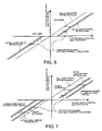
- FIG. 6 is a schematic graph illustrating the relationships between backlashes and characteristics of a commercially produced robot.
- FIG. 7 is a schematic graph illustrating the relationships between backlashes and characteristics adjusted by position servo-compensation.
- FIG. 8 illustrates the concrete configuration of a position servo-compensator for controlling the characteristics as shown in FIG. 7 .
- FIG. 9 is a graph illustrating the relationships between proportional gains and suppression ratios.
- FIG. 10 is a schematic graph illustrating the relationships between backlashes and characteristics adjusted by non-linear position servo-compensation while minimizing a dead band.
- FIG. 11 illustrates the concrete configuration of a non-linear position servo-compensator for controlling the characteristics as shown in FIG. 10 .
- FIG. 12 is a schematic graph illustrating the relationships between backlashes and characteristics adjusted by non-linear position servo-compensation so that, by intentionally widening the dead band, an actual characteristic is provided when the rotating shaft of an actuator rotates beyond a certain angle range.
- FIG. 13 illustrates the concrete configuration of a non-linear position servo-compensator for controlling the characteristics as shown in FIG. 12 .
- FIGS. 1 and 2 are respectively perspective front and rear views of a legged walking robot 100 according to an embodiment of the present invention. Also, FIG. 3 schematically illustrates the joint degrees-of-freedom structure which the legged walking robot 100 is provided with.
- the legged walking robot 100 has a structure of a plurality of limbs formed of upper limbs including two arms and a head 1 , lower limbs including two legs for achieving a locomotive motion, and a trunk connecting the upper limbs and the lower limbs.
- a neck joint for supporting the head 1 has 3 degrees of freedom: i.e., a neck-joint yaw-axis 2 , a neck-joint pitch-axis 3 , and a neck-joint roll-axis 4 .
- Each arm has a shoulder-joint pitch-axis 8 , a shoulder-joint roll-axis 9 , an upper-arm yaw-axis 10 , an elbow-joint pitch-axis 11 , a forearm yaw-axis 12 , a wrist-joint pitch-axis 13 , a wrist-joint roll-axis 14 , and a hand 15 .
- the hand 15 has a multi-joints, multi-degrees-of-freedom structure including a plurality of fingers.
- it is assumed in this specification that the hand 15 has zero degree of freedom since motions of the hands 15 have little affect on the attitude control and the walking control of the legged walking robot 100 . That is to say, each arm has 7 degrees of freedom.
- the trunk has 3 degrees of freedom: i.e., a trunk pitch-axis 5 , a trunk roll-axis 6 , and a trunk yaw-axis 7 .
- Each leg forming the lower limbs has a hip-joint yaw-axis 16 , a hip-joint pitch-axis 17 , a hip-joint roll-axis 18 , a knee-joint pitch-axis 19 , an ankle-joint pitch-axis 20 , an ankle-joint roll-axis 21 , and a foot 22 .
- the cross point between the hip-joint pitch-axis 17 and the hip-joint roll-axis 18 defines a hip-joint location of the legged walking robot 100 according to this embodiment.
- a human foot 22 actually has a structure including a foot bottom having multi-joints multi-degrees-of-freedom, it is assumed that the foot bottom of the legged walking robot 100 according to this embodiment has zero degree of freedom. That is to say, each leg has 6 degrees of freedom.
- the legged walking robot 100 applied for entertainment is not always limited to having 32 degrees of freedom.
- One skilled in the art will appreciate that the number of degrees of freedom or the number of joints can be changed properly in accordance with limitations on design and fabrication, requirement specifications, or the like.
- Each degree-of-freedom of the foregoing legged walking robot 100 is actually implemented by using an actuator.
- the preferable actuator is small and light in consideration of the requirements for assimilating it to the outer shape of a natural human body by eliminating an excessive projection thereof and for performing the attitude control of the unstable biped walking structure thereof.
- a small AC servo actuator that is directly coupled to a gear and that houses a one-chip servo-system is mounted.
- Such an AC servo actuator is disclosed, for example, in Japanese Unexamined Patent Application Publication No. 2000-299970 (Japanese Patent Application H11-33386) which has already been assigned to the same assignee.
- FIG. 4 schematically illustrates the control system configuration of the legged walking robot 100 .
- the legged walking robot 100 has mechanism units 30 , 40 , 5 OR/L, and 60 R/L, each representing the corresponding one of four human limbs, and a control unit 80 performing an adaptive behavior control for achieving a coordinated motion among the mechanisms (hereinafter, postfixes R and L represent right and left, respectively).
- the control unit 80 performs a centralized control over the overall motion of the legged walking robot 100 .
- the control unit 80 has a main control unit 81 including main circuit components (not shown) such as a CPU (central processing unit) and a memory, and a periphery circuit 82 including an interface (not shown) for sending and receiving data and commands to and from a power supply circuit (not shown) and each component of the legged walking robot 100 .
- control unit 80 there is no limitation to an installation location of the control unit 80 in the way of achieving the present invention. Although mounted on the trunk unit 40 in FIG. 4 , the control unit 80 may be mounted on the head unit 30 . Alternatively, the control unit 80 may be installed out of the legged walking robot 100 and may communicate with the body of the legged walking robot 100 by a wire or wireless method.
- the head unit 30 has a neck-joint yaw-axis actuator A 2 , a neck-joint pitch-axis actuator A 3 , and a neck-joint roll-axis actuator A 4 disposed therein for representing the neck-joint yaw-axis 2 , the neck-joint pitch-axis 3 , and the neck-joint roll-axis 4 , respectively.
- the trunk unit 40 has a trunk pitch-axis actuator A 5 , a trunk roll-axis actuator A 6 , and a trunk yaw-axis actuator A 7 disposed therein for representing the trunk pitch-axis 5 , the trunk roll-axis 6 , and the trunk yaw-axis 7 , respectively.
- the arm units 50 R/L are broken down into upper-arm units 51 R/L, elbow-joint units 52 R/L, and forearm units 53 R/L.
- Each of the arm units. 50 R/L has a shoulder-joint pitch-axis actuator A 8 , a shoulder-joint roll-axis actuator A 9 , an upper-arm yaw-axis actuator A 10 , an elbow-joint pitch-axis actuator A 11 , an elbow-joint roll-axis actuator A 12 , a wrist-joint pitch-axis actuator A 13 , and a wrist-joint roll-axis actuator A 14 disposed therein for representing the shoulder-joint pitch-axis 8 , the shoulder-joint roll-axis 9 , the upper-arm yaw-axis 10 , the elbow-joint pitch-axis 11 , an elbow-joint roll-axis 12 , the wrist-joint pitch-axis 13 , and the wrist-join
- the leg units 60 R/L are broken down into thigh units 61 R/L, knee units 62 R/L, and second-thigh units 63 R/L.
- Each of the leg units 60 R/L has a hip-joint yaw-axis actuator A 16 , a hip-joint pitch-axis actuator A 17 , a hip-joint roll-axis actuator A 18 , a knee-joint pitch-axis actuator A 19 , an ankle-joint pitch-axis actuator A 20 , and an ankle-joint roll-axis actuator A 21 disposed therein for representing the hip-joint yaw-axis 16 , the hip-joint pitch-axis 17 , the hip-joint roll-axis 18 , the knee-joint pitch-axis 19 , the ankle-joint pitch-axis 20 , and the ankle-joint roll-axis 21 , respectively.
- Each of the actuators A 2 , A 3 . . . used for the corresponding joint is preferably configured by the foregoing small AC servo actuator that is directly coupled to a gear and that houses a one-chip servo-system.
- the head unit 30 , the trunk unit 40 , the arm units 50 , and the leg units 60 have sub-controllers 35 , 45 , 55 , and 65 for driving the corresponding actuators disposed therein.
- the trunk unit 40 has grounding detection sensors 91 and 92 for detecting the grounding of the foot bottoms of the legs 60 R and 60 L mounted thereon, respectively, and also is provided with an attitude sensor 93 for measuring the attitude thereof.
- Each of the grounding detection sensors 91 and 92 is formed of a proximity sensor, a micro-switch, or the like placed on the foot bottom.
- the attitude sensor 93 is formed of a combination of an acceleration sensor and a gyro-sensor, for example.
- Outputs of the grounding detection sensors 91 and 92 are used to determine whether each of the right and left legs is in a standing state or in an idle state during a motion such as walking or running.
- An output of the attitude sensor 93 is used to detect an inclination and an attitude of the trunk.
- the main controller 80 dynamically modifies a control target in response to the outputs of the sensors 91 to 93 . More particularly, the main controller 80 adaptively controls each of the sub-controllers 35 , 45 , 55 , 65 , thereby achieving a whole-body motion pattern driven in concert by the upper limbs, the trunk, and the lower limbs of the legged walking robot 100 .
- ZMP zero moment point
- TrO trunk motion
- upper limb motions upper limb motions
- waist height and so forth and transmits a command instructing a motion responsive to the above-mentioned setting to each of the sub-controllers 35 , 45 , 55 , and 65
- ZMP means a point at which a moment caused by floor reaction forces during walking is zero
- ZMP trajectory means a trajectory of the moving ZMP, for example, while the legged walking robot 100 is walking as described above.
- the sub-controllers 35 , 45 , 55 , and 65 interpret the corresponding commands received from the main controller 81 and output drive control signals to the corresponding actuators A 2 , A 3 . . . . Also, the main controller 81 outputs control signals for adjusting proportional gains K of the corresponding actuators A 2 , A 3 . . . implementing the corresponding joint degrees-of-freedom.
- the corresponding sub-controllers 35 , 45 , 55 , and 65 adjust the proportional gains of the corresponding actuators A 2 , A 3 . . . , passive degrees-of-freedom corresponding to respective backlashes can be changed (as will be described later).
- the legged walking robot 100 basically has a structure of a plurality of “limbs” formed of rotating joints and its body performs a high-speed switching operation between a closed link mode and an open link mode with the outside world or a working object so as to achieve stable biped walking, a stable two-arms operation, or the like.
- a switching operation between the closed link mode and the open link mode the difference between an expected value and an actual value causes a problem, such as “detachment”, “crash”, or the like, with the outside world, or a working object.
- the legged walking robot 100 is arranged such that each limb has minimum-required passive degrees-of-freedom for removing a dynamic closing error and also the movable range of the limb is properly controlled.
- each limb has minimum-required passive degrees-of-freedom for removing a dynamic closing error and also the movable range of the limb is properly controlled.
- each leg has the following 6 joint degrees-of-freedom (refer to FIG. 3 ).
- Each leg has the hip-joint yaw-axis (TH_Y) disposed at the hip of the body and the ankle-joints at the corresponding flat foot.
- TH_Y hip-joint yaw-axis
- the legged walking robot 100 is bilaterally symmetrical as shown in FIGS. 1 to 3 , it should be understood that the order of priority for the foregoing joints is likewise applied to both of the right and left legs. Also, it is preferable that the corresponding joints of the right and left legs have the same backlash as each other from the view point of making the attitude stabilization control easy.
- the bilaterally symmetrical legs are defined by the following relational expressions.
- the body design of the legged walking robot 100 can be optimized.
- the attitude stabilization control of the biped, legged walking robot 100 can be made easy.
- a backlash of a reducer fixed to an actuator forming each joint is measured and screened, and the actuator with the reducer having the screened backlash is disposed to the corresponding joint so as to form the body.
- a gain of a servo controller of an actuator with a reducer having a uniform backlash is adjusted so as to satisfy one of Conditions 1 to 3.
- each limb has minimum-required, passive degrees-of-freedom for removing a dynamic closing error, and also the movable range of each passive degree-of-freedom is properly controlled.
- a term “closing point” here is a contact point of an idling leg, with which two leg links form a geometrically closed state with a floor surface when the idling leg grounds.
- the term “dynamic closing error” is formed of a distance error and an angle error, between a target attitude and an actual attitude, of a closing member with respect to the closing point (closing surface), that is, a spatially displaced amount of the closing surface.
- the passive degree-of-freedom is mainly achieved by using a backlash of the reducer.
- a backlash of the reducer connected to the actuator for driving the corresponding joint of the leg, even when the actuator for driving the joint has no means for obtaining a torque signal, a high-speed switching operation between the open link mode and the closed link mode can be stably achieved.
- the characteristics of the legs can be defined by physical backlashes, the characteristics of the legs suitable for feed-forward walking can be always obtained.
- the joint As one joint of a lime lies closer to the far end of the limb, the joint has a greater backlash and the sum of the backlashes in each degree-of-freedom of the limb is controlled.
- FIG. 5 illustrates a dynamic closing error during a leg-motion of the biped, legged walking robot 100 .
- the dynamic closing error is a deviation of the actual attitude of the body from its target attitude and is represented by errors of a distance and an angle which vary as time goes on.
- the dynamic closing error itself can be eliminated.
- the first method for optimizing the legged walking robot 100 in which, as one joint of a lime lies closer to the far end of the limb, the joint has a greater backlash and the sum of the backlashes in each degree-of-freedom of the limb is controlled, is not limited to the lower limbs as described above; but it is also applicable to the hands and the upper limbs in the same manner.
- the first method for optimizing the legged walking robot 100 has an aspect of utilizing variations in backlashes of the reducers connected to the corresponding joint actuators. Therefore, when joint actuators for legged walking robots are commercially produced and thus the production of reducers having backlashes varying in a certain variation range is realized, it is hard to say that the foregoing first method in which the backlashes are measured and screened is the best.
- FIG. 6 illustrates the relationships between backlashes and characteristics of a commercially produced robot.
- FIG. 7 illustrates the relationships between backlashes and characteristics adjusted by linear position servo-compensation.
- FIG. 8 illustrates the concrete configuration of a position servo-compensator for controlling the characteristics shown in FIG. 7 .
- the frequency response characteristic of the open-loop gain has a suppression ratio of +30 dB at f ⁇ 1 Hz, by decreasing the proportional gain K down to 1.8, the open-loop gain decreases to +29 dB which is down by the amount of about 1 dB.
- FIG. 9 illustrates the relationships between the proportional gains and the suppression ratios.
- the leg By applying the above-mentioned operation to each joint axis of the leg, the leg obtains the optimized characteristic. Since this operation can be applied to an actuator of any of the joint axes, it can be said that this is a very effective method for designing the characteristic of the leg made of commercially produced components.
- FIG. 10 illustrates the relationships between backlashes and characteristics adjusted by non-linear position servo-compensation.
- the backlashes are adjusted while minimizing a dead band.
- FIG. 11 illustrates the concrete configuration of another position servo-compensator for controlling the characteristics as shown in FIG. 10 .
- FIG. 12 illustrates the relationships between backlashes and characteristics adjusted by non-linear position servo-compensation.
- the backlash is adjusted so as to provide an actual characteristic when the rotating shaft of an actuator rotates beyond a certain angle range.
- FIG. 13 illustrates the concrete configuration of another position servo-compensator for controlling the characteristics as shown in FIG. 12 .
- the legged walking robot 100 has joint degrees-of-freedom of each joint of the trunk, the hip joints, the ankles, and so forth by combining the roll and pitch axes.
- the inventors et al. recommend that the body be designed such that a backlash ⁇ P about the pitch axis is greater than a backlash ⁇ R about the roll axis (i.e., ⁇ P> ⁇ R) for their common joint.
- ⁇ P> ⁇ R a backlash ⁇ P about the pitch axis
- the biped, legged walking robot has rolling and yawing motions which are dominant because of having no yawing motion involved, and thus the robot has a wider stable region in the X-direction than in the Y-direction, thereby leading to the conclusion: ⁇ P> ⁇ R.
- the yaw axis When the yaw axis is disposed at the base of the leg as the joint degrees-of-freedom structure of the body as shown in FIG. 3 , even when a yawing motion occurs, for example, at the time of turning, the motion does not interfere with the pitching or rolling motion of the flat foot in a leg coordinate system (in which the hip joint axis is an origin). That is, the attitude deviation of the flat foot caused by a backlash ⁇ Y of the yaw axis affects only on a yaw-axis angle and can be ignored when a virtually stable region is large enough compared to the deviation.
- the backlash ⁇ Y of the yaw axis interferes with the pitching or rolling motion of the flat foot in the leg coordinate system (in which the hip joint axis is an origin). In this case, it is increasingly important to control the backlash ⁇ Y of the yaw axis.
- the spirit of the present invention is not always limited to a product called a ROBOT. That is, the present invention is applicable to products in other industrial fields such as a toy as long as they are mechanical apparatuses that perform motions imitating human motions by utilizing an electric or magnetic effect.
- an excellent legged walking robot which stably and accurately performs a leg-moving operation by switching its standing modes, for example, by standing alternately with a single or both of right and left movable legs, and an excellent motion control method therefor can be provided.
- an excellent legged walking robot which performs an attitude stabilization control in accordance with a detachment or a crash caused by the difference between an expected value and an actual value when the legged walking robot changes its link mechanism with a floor, a wall, or the like from an open link mechanism to a closed link mechanism, for example, when it switches its standing mode from a single-leg standing mode to a both-legs standing mode, and an excellent motion control method therefor can be provided.
- an excellent legged walking robot which performs a high-speed switching operation between an open link mode and a closed link mode with the outside world or a working object without losing the attitude stability of its body, and an excellent motion control method therefor can be provided.
Abstract
Description
ΔP>ΔR
ΔTH_R<ΔAK_R<ΔTH_P<ΔKN_P<ΔAK_P<ΔTH_Y
ΔLTH_R=ΔRTH_R
ΔLAK_R=ΔRAK_R
ΔLTH_P=ΔRTH_P
ΔLKN_P=ΔRKN_P
ΔLAK_P=ΔRAK_P
ΔLTH_Y=ΔRTH_R
ΔLTH — R+ΔLAK — R=ΔRTH — R+ΔRAK — R<γ
ΔTH — R+ΔLKN — P+ΔLAK — P=ΔRTH — R+ΔRKN — P+ΔRAK P<δ
ΔLTH_Y=ΔRTH_Y
- f(P1, P2, . . . Pi, R1, R2, . . . Yj, Y1, Y2, . . . Yk,
- {dot over (P)}1, {dot over (P)}2, . . . {dot over (P)}i, {dot over (R)}1, {dot over (R)}2, . . . {dot over (Y)}j, {dot over (Y)}1, {dot over (Y)}2, . . . {dot over (Y)}k,
- {umlaut over (P)}1, {umlaut over (P)}2, . . . {umlaut over (P)}i, {umlaut over (R)}1, {umlaut over (R)}2, . . . Ÿj, Ÿ1, Ÿ2, . . . Ÿk,
- ΔP1, ΔP2, . . . ΔPi, ΔR1, ΔR2, . . . ΔR, . . . ΔY1, ΔY2, . . . ΔYk,
- Δ{dot over (P)}1, Δ{dot over (P)}2, . . . Δ{dot over (P)}i, Δ{dot over (R)}1, Δ{dot over (R)}2, . . . Δ{dot over (R)}j . . . Δ{dot over (Y)}1, Δ{dot over (Y)}2, . . . Δ{dot over (Y)}k,
- Δ{umlaut over (P)}1, Δ{umlaut over (P)}2, . . . Δ{umlaut over (P)}i, Δ{umlaut over (R)}1, Δ{umlaut over (R)}2, . . . Δ{umlaut over (R)}j . . . ΔŸj, ΔŸ1, ΔŸ2, . . . ΔŸk, ,t)=presetZNP(ZMPx, ZMPy, ZMPz)+ΔZMP(ΔZMPx, ΔZMPy, ΔZMPz)≦S(Sx, Sy, Sz)
- t:time
- presetZMP(ZMPx, ZMPy, ZMPz): ZMP target position(X-direction target position, Y-direction target position, Z-direction target position) ΔZMP(ΔZMPx, ΔZMPy, ΔZMP2): ZMP difference (X-direction difference, Y-direction difference, Z-direction difference) S(Sx, Sy, Sz): virtually stable region(X-direction region, Y-direction region, Z-direction region)
- f(P1, P2, . . . Pi, R1, R2, . . . Yj, Y1, Y2, . . . Yk,
- {dot over (P)}1, {dot over (P)}2, . . . {dot over (P)}i, {dot over (R)}1, {dot over (R)}2, . . . {dot over (Y)}i, {dot over (Y)}1, {dot over (Y)}2, . . . {dot over (Y)}k,
- {umlaut over (P)}1, {umlaut over (P)}2, . . . {umlaut over (P)}i, {umlaut over (R)}1, {umlaut over (R)}2, . . . Ÿj, Ÿ1, Ÿ2, . . . Ÿk,
- ΔP1, ΔP2, . . . ΔPi, ΔR1, ΔR2, . . . ΔR, . . . ΔY1, ΔY2, . . . ΔYk,
- Δ{dot over (P)}1, Δ{dot over (P)}2, . . . Δ{dot over (P)}i, Δ{dot over (R)}1, Δ{dot over (R)}2, . . . Δ{dot over (R)}j. . . Δ{dot over (Y)}1, Δ{dot over (Y)}2, . . . Δ{dot over (Y)}k
- Δ{umlaut over (P)}1, Δ{umlaut over (P)}2, . . . Δ{umlaut over (P)}i, Δ{umlaut over (R)}1, Δ{umlaut over (R)}2, . . . Δ{umlaut over (R)}{umlaut over (Rj)}. . . ΔŸ1, ΔŸ2, . . . ΔŸk,t): function for computing the actual ZMP position based on target values and differences of corresponding degrees of freedom
- Pi: angular target value in degree-of-freedom about i-th pitch axis {dot over (P)}i: angular-speed target value in degree-of-freedom about i-th pitch axis
- {umlaut over (P)}i: angular-acceleration target value in degree-of-freedom about i-th pitch axis
- ΔPi: deviation from angular target value due to backlash in degree-of-freedom about i-th pitch axis
- Δ{dot over (P)}i: deviation from angular-speed target value due to backlash in degree-of-freedom about i-th pitch axis
- Δ{umlaut over (P)}i: deviation from angular-acceleration target value due to backlash in degree-of-freedom about i-th pitch axis
- Ri: angular target value in degree-of-freedom about i-th roll axis
- {dot over (R)}i: angular-speed target value in degree-of-freedom about i-th roll axis
- {umlaut over (R)}i: angular-acceleration target value in degree-of-freedom about i-th roll axis
- ΔRi: deviation from angular target value due to backlash in degree-of-freedom about i-th roll axis
- Δ{dot over (R)}i: deviation from angular-speed target value due to backlash in degree-of-freedom about i-th roll axis
- Δ{umlaut over (R)}i: deviation from angular-acceleration target value due to backlash in degree-of-freedom about i-th roll axis
- Yi:angular target value in degree-of-freedom about i-th yaw axis
- {dot over (Y)}i: angular-speed target value in degree-of-freedom about i-th yaw axis
- {dot over (Y)}i: angular-acceleration target value in degree-of-freedom about i-th yaw axis
- ΔYi: deviation from angular target value due to backlash in degree-of-freedom about i-th yaw axis
- Δ{dot over (Y)}i: deviation from angular-speed target value due to backlash in degree-of-freedom about i-th yaw axis
- ΔŸi: deviation from angular-acceleration target value due to backlash in degree-of-freedom about i-th yaw axis
- maximum value of
- |g(P1, P2, K Pi, R1, R2, K Yj, Y1, Y2, K Yk,)|=ΔC (ΔCx, ΔCy, ΔCz, ΔCp, ΔCr, ΔCy)
- g(P1, P2, K P1, R1, R2, K Yj, Y1, Y2, K Yk,): function for computing dynamic closing errors based on the corresponding targets values
- ΔC(ΔCx, ΔCy, ΔCz, ΔCp, ΔCr, ΔCy,): maximum value of the dynamic closing errors
- ΔCx: dynamic closing error in X-direction
- ΔCy: dynamic closing error in Y-direction
- ΔCz: dynamic closing error in Z-direction
- ΔCp: dynamic closing error about pitch-axis
- ΔCr: dynamic closing error about roll-axis
- ΔCy: dynamic closing error about yaw-axis
- find minimum values of ΔPi, ΔRj, ΔYk for satisfying the equasion;
ΔC(ΔC x , ΔC y , ΔC z , ΔC p , ΔC r , ΔC y)=0
Claims (20)
Applications Claiming Priority (3)
| Application Number | Priority Date | Filing Date | Title |
|---|---|---|---|
| JP2001233691 | 2001-08-01 | ||
| JP2001-233691 | 2001-08-01 | ||
| PCT/JP2002/007839 WO2003011535A1 (en) | 2001-08-01 | 2002-08-01 | Legged mobile robot and method of controlling operation of the robot |
Publications (2)
| Publication Number | Publication Date |
|---|---|
| US20040122556A1 US20040122556A1 (en) | 2004-06-24 |
| US7278501B2 true US7278501B2 (en) | 2007-10-09 |
Family
ID=19065435
Family Applications (1)
| Application Number | Title | Priority Date | Filing Date |
|---|---|---|---|
| US10/398,070 Expired - Lifetime US7278501B2 (en) | 2001-08-01 | 2002-08-01 | Legged walking robot and motion control method therefor |
Country Status (5)
| Country | Link |
|---|---|
| US (1) | US7278501B2 (en) |
| JP (1) | JP3824608B2 (en) |
| KR (1) | KR100937268B1 (en) |
| CN (1) | CN100503179C (en) |
| WO (1) | WO2003011535A1 (en) |
Cited By (20)
| Publication number | Priority date | Publication date | Assignee | Title |
|---|---|---|---|---|
| US20060056678A1 (en) * | 2004-09-14 | 2006-03-16 | Fumihide Tanaka | Robot apparatus and method of controlling the behavior thereof |
| US20080135312A1 (en) * | 2006-11-20 | 2008-06-12 | Ryosuke Nakamura | Mobile robot |
| US20090069941A1 (en) * | 2007-09-12 | 2009-03-12 | Toyota Jidosha Kabushiki Kaisha | Legged robot and its control method |
| US20090069940A1 (en) * | 2007-09-12 | 2009-03-12 | Toyota Jidosha Kabushiki Kaisha | Legged robot and its control method |
| US20110054681A1 (en) * | 2009-08-28 | 2011-03-03 | Hitachi, Ltd. | Robot |
| US20120158183A1 (en) * | 2010-12-21 | 2012-06-21 | Samsung Electronics Co., Ltd. | Walking robot and control method thereof |
| US8237390B2 (en) | 2010-02-13 | 2012-08-07 | Ivan Godler | Drive unit for legged robots and control method thereof |
| US20130218345A1 (en) * | 2012-02-21 | 2013-08-22 | Smasung Electronics Co., Ltd. | Walking robot and control method thereof |
| US20140060224A1 (en) * | 2011-05-25 | 2014-03-06 | Hitachi, Ltd. | Head structure of robot, and driving method for the head |
| US20160185405A1 (en) * | 2014-12-25 | 2016-06-30 | Mitsubishi Heavy Industries,Ltd | Mobile robot and front end tool |
| US9594377B1 (en) * | 2015-05-12 | 2017-03-14 | Google Inc. | Auto-height swing adjustment |
| US9718186B2 (en) | 2014-10-14 | 2017-08-01 | Janome Sewing Machine Co., Ltd. | Robot |
| US20170309169A1 (en) * | 2016-04-25 | 2017-10-26 | Honda Motor Co., Ltd. | Optical fiber network for transmitting signals in a robot |
| CN108237531A (en) * | 2016-12-26 | 2018-07-03 | 电子科技大学中山学院 | A kind of humanoid robot gait's Learning Control Method |
| US10279487B2 (en) * | 2016-12-29 | 2019-05-07 | UBTECH Robotics Corp. | Foot structure and humanoid robot |
| US10421510B2 (en) * | 2017-07-25 | 2019-09-24 | Sphero, Inc. | Three-legged robotic apparatus |
| US20200180145A1 (en) * | 2018-12-11 | 2020-06-11 | Ubtech Robotics Corp | Robot and leg assembly thereof |
| US10907708B2 (en) * | 2016-10-28 | 2021-02-02 | Sharp Kabushiki Kaisha | Device operating structure and device |
| US11180205B2 (en) * | 2016-04-05 | 2021-11-23 | Hitachi, Ltd. | Humanoid robot |
| US11385139B2 (en) * | 2018-11-21 | 2022-07-12 | Martin E. Best | Active backlash detection methods and systems |
Families Citing this family (20)
| Publication number | Priority date | Publication date | Assignee | Title |
|---|---|---|---|---|
| JP3760186B2 (en) * | 2001-06-07 | 2006-03-29 | 独立行政法人科学技術振興機構 | Biped walking type moving device, walking control device thereof, and walking control method |
| JP4276626B2 (en) * | 2003-05-20 | 2009-06-10 | 富士通株式会社 | Backlash compensation control method, backlash compensation control device, and backlash compensation control program |
| JP3994950B2 (en) * | 2003-09-19 | 2007-10-24 | ソニー株式会社 | Environment recognition apparatus and method, path planning apparatus and method, and robot apparatus |
| JP4457794B2 (en) * | 2004-07-22 | 2010-04-28 | トヨタ自動車株式会社 | robot |
| US20130302132A1 (en) | 2012-05-14 | 2013-11-14 | Kiva Systems, Inc. | System and Method for Maneuvering a Mobile Drive Unit |
| US8649899B2 (en) | 2006-06-19 | 2014-02-11 | Amazon Technologies, Inc. | System and method for maneuvering a mobile drive unit |
| US7912574B2 (en) | 2006-06-19 | 2011-03-22 | Kiva Systems, Inc. | System and method for transporting inventory items |
| US7920962B2 (en) | 2006-06-19 | 2011-04-05 | Kiva Systems, Inc. | System and method for coordinating movement of mobile drive units |
| US8220710B2 (en) | 2006-06-19 | 2012-07-17 | Kiva Systems, Inc. | System and method for positioning a mobile drive unit |
| US8538692B2 (en) | 2006-06-19 | 2013-09-17 | Amazon Technologies, Inc. | System and method for generating a path for a mobile drive unit |
| EP2090962A1 (en) | 2008-02-13 | 2009-08-19 | Research In Motion Limited | Data input device with variable-colour illumination |
| KR20100001567A (en) * | 2008-06-27 | 2010-01-06 | 삼성전자주식회사 | Walking robot and method of controlling the same |
| CN104890757A (en) * | 2015-06-24 | 2015-09-09 | 长春工业大学 | Traveling gear of humanoid robot |
| CN105857431B (en) * | 2016-03-29 | 2017-12-29 | 刘子骞 | A kind of robot reasonable in design |
| CN106184464A (en) * | 2016-09-20 | 2016-12-07 | 上海逸动医学科技有限公司 | A kind of lower limb robot |
| CN107672686B (en) * | 2017-09-20 | 2019-09-20 | 深圳市行者机器人技术有限公司 | A kind of biped robot and its leg damping and energy recycle device |
| CN107962595B (en) * | 2017-11-29 | 2019-11-01 | 北京康力优蓝机器人科技有限公司 | Robot, which falls down to the ground, protects system and method |
| CN109774814A (en) * | 2019-01-16 | 2019-05-21 | 浙江大学 | A kind of Multifeet walking robot foot structure for realizing feedback of contacting to earth |
| CN113428249A (en) * | 2021-07-29 | 2021-09-24 | 桂林电子科技大学 | Monkey-imitating robot for researching animal bounce |
| CN115705048B (en) * | 2021-08-06 | 2023-11-14 | 北京小米机器人技术有限公司 | Control method and device for foot type robot, robot and storage medium |
Citations (15)
| Publication number | Priority date | Publication date | Assignee | Title |
|---|---|---|---|---|
| JPH05245780A (en) | 1992-03-04 | 1993-09-24 | Honda Motor Co Ltd | Controller of leg type mobile robot |
| US5343397A (en) | 1990-09-28 | 1994-08-30 | Honda Giken Kogyo Kabushiki Kaisha | System for controlling locomotion of legged walking robot |
| US5349277A (en) * | 1992-03-12 | 1994-09-20 | Honda Giken Kogyo Kabushiki Kaisha | Control system for legged mobile robot |
| US5355064A (en) | 1992-03-04 | 1994-10-11 | Honda Giken Kogyo Kabushiki Kaisha | Control system for legged mobile robot |
| JPH07205069A (en) | 1993-12-30 | 1995-08-08 | Honda Motor Co Ltd | Walk controller of leg moving robot |
| JP2819323B2 (en) | 1989-11-15 | 1998-10-30 | 本田技研工業株式会社 | Joint control device for legged walking robot |
| US5838130A (en) * | 1996-01-25 | 1998-11-17 | Honda Giken Kogyo Kabushiki Kaisha | Locomotion control system of legged mobile robot |
| JP2001138271A (en) | 1999-11-12 | 2001-05-22 | Sony Corp | Leg type mobile robot and at-overturn motion control method for robot |
| US6243623B1 (en) * | 1997-01-31 | 2001-06-05 | Honda Giken Kogyo Kabushiki Kaisha | Leg type mobile robot control apparatus |
| US6505096B2 (en) * | 1996-12-19 | 2003-01-07 | Honda Giken Kogyo Kabushiki Kaisha | Posture control system of legged mobile robot |
| US6532400B1 (en) * | 2000-03-24 | 2003-03-11 | Intelligent Inference Systems Corporation | Biologically-inspired multi-segmented robot |
| US6564888B1 (en) * | 1999-08-30 | 2003-05-20 | Honda Giken Kogyo Kabushiki Kaisha | Biped mobile robot |
| US6636781B1 (en) * | 2001-05-22 | 2003-10-21 | University Of Southern California | Distributed control and coordination of autonomous agents in a dynamic, reconfigurable system |
| US6643563B2 (en) * | 2001-07-13 | 2003-11-04 | Brooks Automation, Inc. | Trajectory planning and motion control strategies for a planar three-degree-of-freedom robotic arm |
| US20040036437A1 (en) * | 2001-04-03 | 2004-02-26 | Masato Ito | Legged mobile robot and its motion teaching method, and storage medium |
Family Cites Families (1)
| Publication number | Priority date | Publication date | Assignee | Title |
|---|---|---|---|---|
| JPH0768480A (en) * | 1993-09-06 | 1995-03-14 | Mitsubishi Heavy Ind Ltd | Method for controlling articular angle of manipulator |
-
2002
- 2002-08-01 CN CNB028030885A patent/CN100503179C/en not_active Expired - Lifetime
- 2002-08-01 US US10/398,070 patent/US7278501B2/en not_active Expired - Lifetime
- 2002-08-01 KR KR1020037004629A patent/KR100937268B1/en active IP Right Grant
- 2002-08-01 JP JP2003516753A patent/JP3824608B2/en not_active Expired - Lifetime
- 2002-08-01 WO PCT/JP2002/007839 patent/WO2003011535A1/en active Application Filing
Patent Citations (16)
| Publication number | Priority date | Publication date | Assignee | Title |
|---|---|---|---|---|
| JP2819323B2 (en) | 1989-11-15 | 1998-10-30 | 本田技研工業株式会社 | Joint control device for legged walking robot |
| US5343397A (en) | 1990-09-28 | 1994-08-30 | Honda Giken Kogyo Kabushiki Kaisha | System for controlling locomotion of legged walking robot |
| JP2819353B2 (en) | 1990-09-28 | 1998-10-30 | 本田技研工業株式会社 | Walking control device for legged mobile robot |
| US5355064A (en) | 1992-03-04 | 1994-10-11 | Honda Giken Kogyo Kabushiki Kaisha | Control system for legged mobile robot |
| JPH05245780A (en) | 1992-03-04 | 1993-09-24 | Honda Motor Co Ltd | Controller of leg type mobile robot |
| US5349277A (en) * | 1992-03-12 | 1994-09-20 | Honda Giken Kogyo Kabushiki Kaisha | Control system for legged mobile robot |
| JPH07205069A (en) | 1993-12-30 | 1995-08-08 | Honda Motor Co Ltd | Walk controller of leg moving robot |
| US5838130A (en) * | 1996-01-25 | 1998-11-17 | Honda Giken Kogyo Kabushiki Kaisha | Locomotion control system of legged mobile robot |
| US6505096B2 (en) * | 1996-12-19 | 2003-01-07 | Honda Giken Kogyo Kabushiki Kaisha | Posture control system of legged mobile robot |
| US6243623B1 (en) * | 1997-01-31 | 2001-06-05 | Honda Giken Kogyo Kabushiki Kaisha | Leg type mobile robot control apparatus |
| US6564888B1 (en) * | 1999-08-30 | 2003-05-20 | Honda Giken Kogyo Kabushiki Kaisha | Biped mobile robot |
| JP2001138271A (en) | 1999-11-12 | 2001-05-22 | Sony Corp | Leg type mobile robot and at-overturn motion control method for robot |
| US6532400B1 (en) * | 2000-03-24 | 2003-03-11 | Intelligent Inference Systems Corporation | Biologically-inspired multi-segmented robot |
| US20040036437A1 (en) * | 2001-04-03 | 2004-02-26 | Masato Ito | Legged mobile robot and its motion teaching method, and storage medium |
| US6636781B1 (en) * | 2001-05-22 | 2003-10-21 | University Of Southern California | Distributed control and coordination of autonomous agents in a dynamic, reconfigurable system |
| US6643563B2 (en) * | 2001-07-13 | 2003-11-04 | Brooks Automation, Inc. | Trajectory planning and motion control strategies for a planar three-degree-of-freedom robotic arm |
Non-Patent Citations (2)
| Title |
|---|
| Patent Abstracts of Japan, publication No. 03-161290 dated Jul. 11, 1991. |
| Patent Abstracts of Japan, publication No. 07-068480 dated Mar. 14, 1995. |
Cited By (36)
| Publication number | Priority date | Publication date | Assignee | Title |
|---|---|---|---|---|
| US20060056678A1 (en) * | 2004-09-14 | 2006-03-16 | Fumihide Tanaka | Robot apparatus and method of controlling the behavior thereof |
| US8315454B2 (en) * | 2004-09-14 | 2012-11-20 | Sony Corporation | Robot apparatus and method of controlling the behavior thereof |
| US20080135312A1 (en) * | 2006-11-20 | 2008-06-12 | Ryosuke Nakamura | Mobile robot |
| US7658245B2 (en) * | 2006-11-20 | 2010-02-09 | Hitachi, Ltd. | Mobile robot |
| US8386076B2 (en) * | 2007-09-12 | 2013-02-26 | Toyota Jidosha Kabushiki Kaisha | Legged robot and its control method |
| US20090069941A1 (en) * | 2007-09-12 | 2009-03-12 | Toyota Jidosha Kabushiki Kaisha | Legged robot and its control method |
| US20090069940A1 (en) * | 2007-09-12 | 2009-03-12 | Toyota Jidosha Kabushiki Kaisha | Legged robot and its control method |
| US8340817B2 (en) * | 2007-09-12 | 2012-12-25 | Toyota Jidosha Kabushiki Kaisha | Legged robot and its control method |
| US20110054681A1 (en) * | 2009-08-28 | 2011-03-03 | Hitachi, Ltd. | Robot |
| US8237390B2 (en) | 2010-02-13 | 2012-08-07 | Ivan Godler | Drive unit for legged robots and control method thereof |
| US20120158183A1 (en) * | 2010-12-21 | 2012-06-21 | Samsung Electronics Co., Ltd. | Walking robot and control method thereof |
| US20140060224A1 (en) * | 2011-05-25 | 2014-03-06 | Hitachi, Ltd. | Head structure of robot, and driving method for the head |
| US9016158B2 (en) * | 2011-05-25 | 2015-04-28 | Hitachi, Ltd. | Head structure of robot, and driving method for the head |
| US20130218345A1 (en) * | 2012-02-21 | 2013-08-22 | Smasung Electronics Co., Ltd. | Walking robot and control method thereof |
| US9073209B2 (en) * | 2012-02-21 | 2015-07-07 | Samsung Electronics Co., Ltd. | Walking robot and control method thereof |
| US9718186B2 (en) | 2014-10-14 | 2017-08-01 | Janome Sewing Machine Co., Ltd. | Robot |
| US20160185405A1 (en) * | 2014-12-25 | 2016-06-30 | Mitsubishi Heavy Industries,Ltd | Mobile robot and front end tool |
| US9845122B2 (en) * | 2014-12-25 | 2017-12-19 | Mitsubishi Heavy Industries, Ltd. | Mobile robot and front end tool |
| US10220897B2 (en) | 2014-12-25 | 2019-03-05 | Mitsubishi Heavy Industries, Ltd. | Mobile robot and front end tool |
| US9594377B1 (en) * | 2015-05-12 | 2017-03-14 | Google Inc. | Auto-height swing adjustment |
| US20230333559A1 (en) * | 2015-05-12 | 2023-10-19 | Boston Dynamics, Inc. | Auto swing-height adjustment |
| US11726481B2 (en) * | 2015-05-12 | 2023-08-15 | Boston Dynamics, Inc. | Auto-swing height adjustment |
| US20220057800A1 (en) * | 2015-05-12 | 2022-02-24 | Boston Dynamics, Inc. | Auto-Swing Height Adjustment |
| US11188081B2 (en) * | 2015-05-12 | 2021-11-30 | Boston Dynamics, Inc. | Auto-swing height adjustment |
| US10528051B1 (en) | 2015-05-12 | 2020-01-07 | Boston Dynamics, Inc. | Auto-height swing adjustment |
| US11180205B2 (en) * | 2016-04-05 | 2021-11-23 | Hitachi, Ltd. | Humanoid robot |
| US20170309169A1 (en) * | 2016-04-25 | 2017-10-26 | Honda Motor Co., Ltd. | Optical fiber network for transmitting signals in a robot |
| US9997066B2 (en) * | 2016-04-25 | 2018-06-12 | Honda Motor Co., Ltd. | Optical fiber network for transmitting signals in a robot |
| US10907708B2 (en) * | 2016-10-28 | 2021-02-02 | Sharp Kabushiki Kaisha | Device operating structure and device |
| CN108237531A (en) * | 2016-12-26 | 2018-07-03 | 电子科技大学中山学院 | A kind of humanoid robot gait's Learning Control Method |
| US10279487B2 (en) * | 2016-12-29 | 2019-05-07 | UBTECH Robotics Corp. | Foot structure and humanoid robot |
| US10421510B2 (en) * | 2017-07-25 | 2019-09-24 | Sphero, Inc. | Three-legged robotic apparatus |
| US11385139B2 (en) * | 2018-11-21 | 2022-07-12 | Martin E. Best | Active backlash detection methods and systems |
| US11906397B2 (en) | 2018-11-21 | 2024-02-20 | Martin E. Best | Active backlash detection methods and systems |
| US10836032B2 (en) * | 2018-12-11 | 2020-11-17 | Ubtech Robotics Corp | Robot and leg assembly thereof |
| US20200180145A1 (en) * | 2018-12-11 | 2020-06-11 | Ubtech Robotics Corp | Robot and leg assembly thereof |
Also Published As
| Publication number | Publication date |
|---|---|
| KR100937268B1 (en) | 2010-01-18 |
| KR20040029948A (en) | 2004-04-08 |
| US20040122556A1 (en) | 2004-06-24 |
| CN100503179C (en) | 2009-06-24 |
| CN1476372A (en) | 2004-02-18 |
| JP3824608B2 (en) | 2006-09-20 |
| JPWO2003011535A1 (en) | 2004-11-18 |
| WO2003011535A1 (en) | 2003-02-13 |
Similar Documents
| Publication | Publication Date | Title |
|---|---|---|
| US7278501B2 (en) | Legged walking robot and motion control method therefor | |
| US6898485B2 (en) | Device and method for controlling operation of legged robot, and robot device | |
| KR100843863B1 (en) | Legged mobile robot and control method thereof, leg structure of legged mobile robot, and mobile leg unit for legged mobile robot | |
| KR100959472B1 (en) | Robot device and control method of robot device | |
| US7386364B2 (en) | Operation control device for leg-type mobile robot and operation control method, and robot device | |
| KR100687461B1 (en) | Robot And Knuckle Apparatus For Robot | |
| US6961640B2 (en) | Motion control for a legged robot | |
| US7013201B2 (en) | Legged mobile robot and method of controlling operation of the same | |
| KR20010050543A (en) | Ambulation control apparatus and ambulation control method of robot | |
| WO2004033160A1 (en) | Robot device operation control device and operation control method | |
| JP3528171B2 (en) | Mobile robot apparatus and overturn control method for mobile robot apparatus | |
| JP3674779B2 (en) | Motion control device and motion control method for legged mobile robot, and robot device | |
| CN113721647B (en) | Dynamic step-up control method for biped robot | |
| JP2001138273A (en) | Leg type mobile and its controlling method | |
| JP2004148491A (en) | Apparatus and method for controlling operation of robot system, and its computer program | |
| JP2004106184A (en) | Mobile robot device and control method used for device | |
| JP2006095661A (en) | Robot device and wheel device for robot | |
| JP2004025434A (en) | Motion control device and method for leg-type moving robot, and robot device |
Legal Events
| Date | Code | Title | Description |
|---|---|---|---|
| AS | Assignment |
Owner name: SONY CORPORATION, JAPAN Free format text: ASSIGNMENT OF ASSIGNORS INTEREST;ASSIGNORS:MORI, NAOTO;IRIBE, MASATSUGU;YAMAGUCHI, JINICHI;REEL/FRAME:014553/0399;SIGNING DATES FROM 20030610 TO 20030918 |
|
| AS | Assignment |
Owner name: JINICHI YAMAGUCHI, JAPAN Free format text: ASSIGNMENT OF ASSIGNORS INTEREST;ASSIGNOR:SONY CORPORATION;REEL/FRAME:019543/0515 Effective date: 20070529 Owner name: SONY CORPORATION, JAPAN Free format text: ASSIGNMENT OF ASSIGNORS INTEREST;ASSIGNOR:SONY CORPORATION;REEL/FRAME:019543/0515 Effective date: 20070529 |
|
| STCF | Information on status: patent grant |
Free format text: PATENTED CASE |
|
| FEPP | Fee payment procedure |
Free format text: PAYOR NUMBER ASSIGNED (ORIGINAL EVENT CODE: ASPN); ENTITY STATUS OF PATENT OWNER: LARGE ENTITY |
|
| CC | Certificate of correction | ||
| FPAY | Fee payment |
Year of fee payment: 4 |
|
| FPAY | Fee payment |
Year of fee payment: 8 |
|
| MAFP | Maintenance fee payment |
Free format text: PAYMENT OF MAINTENANCE FEE, 12TH YEAR, LARGE ENTITY (ORIGINAL EVENT CODE: M1553); ENTITY STATUS OF PATENT OWNER: LARGE ENTITY Year of fee payment: 12 |