US7277464B2 - Method and apparatus for controlling the output of a gas discharge laser system - Google Patents
Method and apparatus for controlling the output of a gas discharge laser system Download PDFInfo
- Publication number
- US7277464B2 US7277464B2 US11/035,938 US3593805A US7277464B2 US 7277464 B2 US7277464 B2 US 7277464B2 US 3593805 A US3593805 A US 3593805A US 7277464 B2 US7277464 B2 US 7277464B2
- Authority
- US
- United States
- Prior art keywords
- gas
- multidimensional
- gas discharge
- laser
- discharge laser
- Prior art date
- Legal status (The legal status is an assumption and is not a legal conclusion. Google has not performed a legal analysis and makes no representation as to the accuracy of the status listed.)
- Expired - Fee Related, expires
Links
Images


Classifications
-
- H—ELECTRICITY
- H01—ELECTRIC ELEMENTS
- H01S—DEVICES USING THE PROCESS OF LIGHT AMPLIFICATION BY STIMULATED EMISSION OF RADIATION [LASER] TO AMPLIFY OR GENERATE LIGHT; DEVICES USING STIMULATED EMISSION OF ELECTROMAGNETIC RADIATION IN WAVE RANGES OTHER THAN OPTICAL
- H01S3/00—Lasers, i.e. devices using stimulated emission of electromagnetic radiation in the infrared, visible or ultraviolet wave range
- H01S3/02—Constructional details
- H01S3/03—Constructional details of gas laser discharge tubes
- H01S3/036—Means for obtaining or maintaining the desired gas pressure within the tube, e.g. by gettering, replenishing; Means for circulating the gas, e.g. for equalising the pressure within the tube
-
- H—ELECTRICITY
- H01—ELECTRIC ELEMENTS
- H01S—DEVICES USING THE PROCESS OF LIGHT AMPLIFICATION BY STIMULATED EMISSION OF RADIATION [LASER] TO AMPLIFY OR GENERATE LIGHT; DEVICES USING STIMULATED EMISSION OF ELECTROMAGNETIC RADIATION IN WAVE RANGES OTHER THAN OPTICAL
- H01S3/00—Lasers, i.e. devices using stimulated emission of electromagnetic radiation in the infrared, visible or ultraviolet wave range
- H01S3/09—Processes or apparatus for excitation, e.g. pumping
- H01S3/097—Processes or apparatus for excitation, e.g. pumping by gas discharge of a gas laser
-
- H—ELECTRICITY
- H01—ELECTRIC ELEMENTS
- H01S—DEVICES USING THE PROCESS OF LIGHT AMPLIFICATION BY STIMULATED EMISSION OF RADIATION [LASER] TO AMPLIFY OR GENERATE LIGHT; DEVICES USING STIMULATED EMISSION OF ELECTROMAGNETIC RADIATION IN WAVE RANGES OTHER THAN OPTICAL
- H01S3/00—Lasers, i.e. devices using stimulated emission of electromagnetic radiation in the infrared, visible or ultraviolet wave range
- H01S3/10—Controlling the intensity, frequency, phase, polarisation or direction of the emitted radiation, e.g. switching, gating, modulating or demodulating
- H01S3/13—Stabilisation of laser output parameters, e.g. frequency or amplitude
- H01S3/131—Stabilisation of laser output parameters, e.g. frequency or amplitude by controlling the active medium, e.g. by controlling the processes or apparatus for excitation
- H01S3/134—Stabilisation of laser output parameters, e.g. frequency or amplitude by controlling the active medium, e.g. by controlling the processes or apparatus for excitation in gas lasers
-
- H—ELECTRICITY
- H01—ELECTRIC ELEMENTS
- H01S—DEVICES USING THE PROCESS OF LIGHT AMPLIFICATION BY STIMULATED EMISSION OF RADIATION [LASER] TO AMPLIFY OR GENERATE LIGHT; DEVICES USING STIMULATED EMISSION OF ELECTROMAGNETIC RADIATION IN WAVE RANGES OTHER THAN OPTICAL
- H01S3/00—Lasers, i.e. devices using stimulated emission of electromagnetic radiation in the infrared, visible or ultraviolet wave range
- H01S3/14—Lasers, i.e. devices using stimulated emission of electromagnetic radiation in the infrared, visible or ultraviolet wave range characterised by the material used as the active medium
- H01S3/22—Gases
- H01S3/223—Gases the active gas being polyatomic, i.e. containing two or more atoms
- H01S3/225—Gases the active gas being polyatomic, i.e. containing two or more atoms comprising an excimer or exciplex
-
- H—ELECTRICITY
- H01—ELECTRIC ELEMENTS
- H01S—DEVICES USING THE PROCESS OF LIGHT AMPLIFICATION BY STIMULATED EMISSION OF RADIATION [LASER] TO AMPLIFY OR GENERATE LIGHT; DEVICES USING STIMULATED EMISSION OF ELECTROMAGNETIC RADIATION IN WAVE RANGES OTHER THAN OPTICAL
- H01S3/00—Lasers, i.e. devices using stimulated emission of electromagnetic radiation in the infrared, visible or ultraviolet wave range
- H01S3/23—Arrangements of two or more lasers not provided for in groups H01S3/02 - H01S3/22, e.g. tandem arrangements of separate active media
- H01S3/2366—Arrangements of two or more lasers not provided for in groups H01S3/02 - H01S3/22, e.g. tandem arrangements of separate active media comprising a gas as the active medium
-
- H—ELECTRICITY
- H01—ELECTRIC ELEMENTS
- H01S—DEVICES USING THE PROCESS OF LIGHT AMPLIFICATION BY STIMULATED EMISSION OF RADIATION [LASER] TO AMPLIFY OR GENERATE LIGHT; DEVICES USING STIMULATED EMISSION OF ELECTROMAGNETIC RADIATION IN WAVE RANGES OTHER THAN OPTICAL
- H01S3/00—Lasers, i.e. devices using stimulated emission of electromagnetic radiation in the infrared, visible or ultraviolet wave range
- H01S3/10—Controlling the intensity, frequency, phase, polarisation or direction of the emitted radiation, e.g. switching, gating, modulating or demodulating
- H01S3/10069—Memorized or pre-programmed characteristics, e.g. look-up table [LUT]
-
- H—ELECTRICITY
- H01—ELECTRIC ELEMENTS
- H01S—DEVICES USING THE PROCESS OF LIGHT AMPLIFICATION BY STIMULATED EMISSION OF RADIATION [LASER] TO AMPLIFY OR GENERATE LIGHT; DEVICES USING STIMULATED EMISSION OF ELECTROMAGNETIC RADIATION IN WAVE RANGES OTHER THAN OPTICAL
- H01S3/00—Lasers, i.e. devices using stimulated emission of electromagnetic radiation in the infrared, visible or ultraviolet wave range
- H01S3/10—Controlling the intensity, frequency, phase, polarisation or direction of the emitted radiation, e.g. switching, gating, modulating or demodulating
- H01S3/102—Controlling the intensity, frequency, phase, polarisation or direction of the emitted radiation, e.g. switching, gating, modulating or demodulating by controlling the active medium, e.g. by controlling the processes or apparatus for excitation
- H01S3/104—Controlling the intensity, frequency, phase, polarisation or direction of the emitted radiation, e.g. switching, gating, modulating or demodulating by controlling the active medium, e.g. by controlling the processes or apparatus for excitation in gas lasers
-
- H—ELECTRICITY
- H01—ELECTRIC ELEMENTS
- H01S—DEVICES USING THE PROCESS OF LIGHT AMPLIFICATION BY STIMULATED EMISSION OF RADIATION [LASER] TO AMPLIFY OR GENERATE LIGHT; DEVICES USING STIMULATED EMISSION OF ELECTROMAGNETIC RADIATION IN WAVE RANGES OTHER THAN OPTICAL
- H01S3/00—Lasers, i.e. devices using stimulated emission of electromagnetic radiation in the infrared, visible or ultraviolet wave range
- H01S3/10—Controlling the intensity, frequency, phase, polarisation or direction of the emitted radiation, e.g. switching, gating, modulating or demodulating
- H01S3/13—Stabilisation of laser output parameters, e.g. frequency or amplitude
- H01S3/1306—Stabilisation of the amplitude
-
- H—ELECTRICITY
- H01—ELECTRIC ELEMENTS
- H01S—DEVICES USING THE PROCESS OF LIGHT AMPLIFICATION BY STIMULATED EMISSION OF RADIATION [LASER] TO AMPLIFY OR GENERATE LIGHT; DEVICES USING STIMULATED EMISSION OF ELECTROMAGNETIC RADIATION IN WAVE RANGES OTHER THAN OPTICAL
- H01S3/00—Lasers, i.e. devices using stimulated emission of electromagnetic radiation in the infrared, visible or ultraviolet wave range
- H01S3/14—Lasers, i.e. devices using stimulated emission of electromagnetic radiation in the infrared, visible or ultraviolet wave range characterised by the material used as the active medium
- H01S3/22—Gases
- H01S3/223—Gases the active gas being polyatomic, i.e. containing two or more atoms
- H01S3/225—Gases the active gas being polyatomic, i.e. containing two or more atoms comprising an excimer or exciplex
- H01S3/2258—F2, i.e. molecular fluoride is comprised for lasing around 157 nm
-
- H—ELECTRICITY
- H01—ELECTRIC ELEMENTS
- H01S—DEVICES USING THE PROCESS OF LIGHT AMPLIFICATION BY STIMULATED EMISSION OF RADIATION [LASER] TO AMPLIFY OR GENERATE LIGHT; DEVICES USING STIMULATED EMISSION OF ELECTROMAGNETIC RADIATION IN WAVE RANGES OTHER THAN OPTICAL
- H01S3/00—Lasers, i.e. devices using stimulated emission of electromagnetic radiation in the infrared, visible or ultraviolet wave range
- H01S3/23—Arrangements of two or more lasers not provided for in groups H01S3/02 - H01S3/22, e.g. tandem arrangements of separate active media
- H01S3/2308—Amplifier arrangements, e.g. MOPA
Definitions
- the present invention relates to a fluorine gas discharge laser system and control of replenishment of fluorine gas as the gas discharge laser operates and consumes fluorine.
- Halogen based, and particularly fluorine based gas discharge lasers e.g., KrF and ArF excimer lasers and molecular fluorine lasers are well known. They have been implemented as an oscillator, in which, e.g., a gas discharge laser, which is in a resonator cavity configuration, and with a very accurate line narrowing module or package (“LNM” or “LNP”) produces an output laser light pulse beam of pulses with a precisely defined center wavelength and a bandwidth on the order of femtometers.
- LNM line narrowing module or package
- the output parameters of laser output light pulse beam pulses from the oscillator gas discharge laser depend on a variety of operating parameters, including the initial makeup of the gases, usually a halogen, e.g., fluorine, a noble gas, e.g., argon or krypton, and a buffer, e.g., neon.
- a halogen e.g., fluorine
- a noble gas e.g., argon or krypton
- a buffer e.g., neon.
- the makeup of these gases in the oscillator also varies over time, particularly as the halogen is consumed in the creating of the laser light output pulse beam of pulses by the gas discharges occurring within the chamber containing the gases in the oscillator. It has been found that previously used techniques for accounting for such things as the changes in the gas composition over time in oscillating gas discharge lasers are not as effective as is desirable.
- 6,005,879 entitled PULSE ENERGY CONTROL FOR EXCIMER LASERS relates to micro-bursts of fluorine injection comprising controlled periodic fluorine injections at intervals as low as about 3 to 5 minutes, also said to be an “almost continuous basis.”
- the feedback for control is ⁇ E/ ⁇ V, the change in laser output with change in charging voltage.
- U.S. Published patent application No. 20020186739, filed in the name of Sandstrom et al., and published on Dec. 12, 2002, entitled INJECTION SEEDED F2 LASER WITH WAVELENGTH CONTROL, and assigned to Cymer relates to adjusting laser gas pressure, buffer gas mix, and F 2 partial pressure to control the “centerline wavelength” of the output beam in a two chamber laser.
- Cymer Docket No. 2002-0070-01 inventors Ishihara, et al., filed on Nov. 27, 2002, Ser. No. 60/429,493, entitled AUTOMATIC GAS CONTROL SYSTEM FOR A TWO CHAMBER LASER, and assigned to Cymer, relates to F 2 replenishment based upon the history of consumption rates over the laser life.
- Cymer Docket No. 2003-0001-01 inventors Rule, et al., filed on Jan. 31, 2003, Ser. No. 10/356,168, entitled AUTOMATIC GAS CONTROL SYSTEM FOR A GAS DISCHARGE LASER, and assigned to Cymer, relates to F 2 replenishment based upon the history of consumption rates over the laser life.
- U.S. Pat. No. 6,330,267 issued to Vogler, et al. on Dec. 11, 2001, entitled PERFORMANCE CONTROL SYSTEM AND METHOD FOR GAS DISCHARGE LASERS, and assigned to Lambda Physik, relates to halogen gas replenishment based upon the slope of an output parameter of the laser compared to an expected slope of the parameter giving an estimate of the deviation, of the halogen from the optimum, e.g., the laser output versus input energy.
- U.S. Pat. No. 6,389,052 issued to Albrecht, et al.
- a laser having a gas replenishment control system using a processor employing an algorithm for periodically determining gas actions for the gas supply unit to smoothly perform the gas actions which stabilize a composition of the laser gas mixture within the discharge chamber and to stabilize significant parameters of the laser beam, and in which the gas supply unit and said processor are configured to permit a quantity in a range substantially between 0.0001 mbar and 0.2 mbar of said halogen-containing constituent gas to inject into said laser tube at selected intervals, such that a degradation of the halogen-containing constituent gas is automatically compensated without substantially disturbing laser beam parameters, and also, e.g., with the gas is a halogen and the processor also controls discharge voltage based at least in part on energy information received from an energy detector; and also, e.g., the control is based on discharge voltage variation necessary for a predetermined output energy.
- U.S. Pat. No. 6,504,861 issued to Albrecht, et al. on Jan. 7, 2003, entitled LASER GAS REPLENISHMENT METHOD, assigned to Lambda Physik, relates to replenishment periodically between a certain range of mbar of a gas, based upon a known amount injected in a prior replenishment which amount injected in the prior replenishment was based on a known amount of the gas in the chamber prior to the last injection; and also varying the intervals based on the same criteria.
- U.S. Pat. No. 6,529,533 issued to Voss on Mar.
- No. 5,450,436 issued to Mizoguchi, et al. on Sep. 12, 1995, entitled LASER GAS REPLENISHING APPARATUS AND METHOD IN EXCIMER LASER SYSTEM, and assigned to Komatsu relates to halogen gas replenishment based upon beam width and with periodic injection, i.e., with a predetermined amount varied up or down based on beam width; or alternatively injecting a halogen constituent gas at predetermined intervals to a level that maintains total pressure and stopping the exhaust while injecting; or alternatively injecting a predetermined amount after a predetermined number of pulses; or alternatively based on accumulated pulses and pulse rate; or alternatively replenishing the halogen on one pulse count and the rare gas on another and exhausting to maintain pressure; or alternatively replenishing the halogen based on pulse count and the rare gas based on charging voltage.
- U.S. Pat. No. 5,754,579, issued to Mizoguchi, et al. on May 19, 1998, entitled LASER GAS CONTROLLER AND CHARGING/DISCHARGING DEVICE FOR DISCHARGE-EXCITED LASER, and assigned to Komatsu relates to gas replenishment/exhaust based upon an output of the laser or alternatively based upon the charging voltage; including also bandwidth.
- U.S. Pat. No. 6,130,904 issued to Ishihara, et al.
- Japanese Patent No. 2601410 the Published Application of which 08008481 was published on Jan. 12, 1996 (application 06134468 filed on Jun. 16, 1994), assigned to Komatsu (corresponding to U.S. Pat. No. 5,754,579, which relates to claims priority from this application and another), refers to gas replenishment based on charging voltage or beam width and charging voltage.
- Japanese Patent No. 2701184 the Published Application of which (05192555 JP) was published on Apr. 23, 1993 (application 03290618 filed on Oct. 9, 1991), assigned to Komatsu, refers to controlling the mixture of the constituent gas mixture, based upon pulse count.
- Japanese Patent No. 3297108 issued on Jul. 2, 2002, assigned to Komatsu (U.S. Pat. No.
- Japanese Published Patent Application No. 09097951 JP published on Apr. 1, 1997, based on a Japanese Patent Application No. 07289105, filed on Sep. 29, 1995 by Senrin, et al., entitled EXCIMER LASER APPARATUS, and assigned to Nissin Electric, refers to replenishment based upon charging voltage.
- Japanese Published Patent application No. 2000022255, published on Jan. 21, 2000, with inventors Omi, et al., entitled METHOD FOR STABILIZING AND CONTROLLING FLUORINE GAS CONCENTRATION AND CONTROL MECHANISM THEREOF based on a Japanese Patent Application No. JP19980191178, filed on Jul.
- a method and apparatus for controlling the output of a gas discharge laser may comprise establishing a multidimensional variable state space comprising a coordinate system having at least two coordinates, each coordinate comprising a selected variable representing an operating or output parameter of the gas discharge laser; tracking a multidimensional operating point in the multidimensional variable state space according to the variation of the selected variables in the gas discharge laser to determine the position of the multidimensional operating point in the multidimensional state space; determining from the position of the multidimensional operating point in the multidimensional operating space a region from a plurality of defined regions in the multidimensional operating space in which the multidimensional operating point is located and identifying the region; based upon the identity of the identified region, and parameters of that region relative to the condition of an actuator in the gas discharge laser, determining a necessary modification to the actuator for the gas discharge laser to attempt to move the multidimensional operating point from the parameters indicated by the position of the multidimensional operating point being in the particular region to a preselected location in the coordinate system.
- the multidimensional state space may comprise a two-dimensional state space.
- the two dimensional state space may comprise axis as the operating voltage of the gas discharge laser and the other axis as the bandwidth of the gas discharge laser output laser light pulse beam.
- the regions in the multidimensional state space may comprise an inner target, a first outer region having an inner boundary adjacent to the inner target and an outer boundary and a second outer region adjacent to the outer boundary of the first outer region.
- the inner target may comprise the origin of the coordinate system.
- a parameter used in defining the origin of the coordinate system may comprise duty cycle.
- the actuator may comprise the composition of the gas mixture inside of the gas discharge laser.
- the method may comprise establishing a multidimensional variable state space comprising a coordinate system having at least two coordinates, each coordinate comprising a selected variable representing an operating or output parameter of the gas discharge laser; changing the gas mixture in the gas discharge laser by injection of at least one constituent gas in the gas mixture at least part of which injection is based upon a calculated estimate of consumption of the at least one constituent gas in the gas mixture in the gas discharge laser from a prior change in the gas mixture; allowing the gas discharge laser to operate for a selected period of time with the changed gas mixture; determining the position of an operating point in the multidimensional variable state space and based upon the location of the operating point in the multidimensional state space determining a respective boost factor to modify the calculated estimate of consumption for the current change of the gas mixture.
- the multidimensional state space may comprise a two dimensional state space having two coordinates: the first coordinate is measure of a spectral characteristic of the gas discharge laser output light pulse beam; and the second coordinate is another operating or output parameter of the gas discharge laser.
- the boost factor may comprise a ⁇ 1, ⁇ 2 or 0.
- the position of the operating point in the multidimensional state space may be indicative of a needed correction to the spectral characteristic of the output laser light pulse beam; and the method may comprise changing the spectral characteristic of the laser output light pulse beam using a gas injection.
- the apparatus may comprise means for establishing a multidimensional variable state space comprising a coordinate system having at least two coordinates, each coordinate comprising a selected variable representing an operating parameter of the gas discharge laser; means for tracking a multidimensional operating point in the multidimensional variable state space according to the variation of the selected variables in the gas discharge laser to determine the position of the multidimensional operating point in the multidimensional state space; means for determining from the position of the multidimensional operating point in the multidimensional operating space a region from a plurality of defined regions in the multidimensional operating space in which the multidimensional operating point is located and identifying the region; inject determining means, based upon the identity of the identified region, and parameters of that region relative to the condition of an actuator in the gas discharge laser, for determining a necessary modification to the actuator for the gas discharge laser to attempt to move the multidimensional operating point from the parameters indicated by the position of the multidimensional operating point being in the particular region to a preselected location in the coordinate system or may comprise means for establishing a multidimensional variable state space comprising a coordinate system having at least two coordinate
- the method may comprise establishing a two dimensional variable state space comprising a coordinate system having two coordinates, each coordinate comprising a selected variable representing an operating parameter of the gas discharge laser; tracking a two dimensional operating point in the two dimensional variable state space according to the variation of the selected variables in the gas discharge laser to determine the position the two dimensional operating point along an F 2 consumption axis in the two dimensional state space; determining from the position of the two dimensional operating point on the F 2 consumption axis a region of gas consumption occupied by the operating point; based upon the region on the F 2 consumption axis determining a necessary modification to the actuator for the gas discharge laser to attempt to move the multidimensional operating point based on an estimated consumption rate to a preselected location on the F 2 consumption axis.
- the two dimensional state space may comprise one coordinate axis as the operating voltage of the gas discharge laser and the other coordinate axis as another output or operating parameter of the gas discharge laser.
- the other output or operating parameter of the gas discharge laser may comprise the bandwidth of an output laser light pulse beam pulse.
- the regions on the F 2 consumption axis may comprise an inner target, an inner region bounded on the inner target, and an outer boundary of the inner region, and an outer region adjacent to the outer boundary of the inner region. An inner and an outer region may be defined on each side of the coordinate system origin.
- the method may comprise establishing a two dimensional variable state space comprising a coordinate system having two coordinates, each coordinate comprising a selected variable representing an operating or output parameter of the gas discharge laser; changing the gas mixture in the gas discharge laser by injection of at least one constituent gas in the gas mixture at least part of which injection is based upon a calculated estimate of consumption of the at least one constituent gas in the gas mixture in the gas discharge laser from a prior change in the gas mixture; allowing the gas discharge laser to operate for a selected period of time with the changed gas mixture; determining the position of an operating point in the multidimensional variable state space and based upon the location of the operating point in the multidimensional state space determining a respective boost factor to modify the calculated estimate of consumption for the current change of the gas mixture.
- the multidimensional state space nay comprise a two dimensional state space having two coordinates: the first coordinate may comprise a measure of a spectral characteristic of the gas discharge laser output light pulse beam; and the second coordinate is another operating or output parameter of the gas discharge laser.
- the multidimensional state space coordinates define regions of possible change of the gas mixture in the gas discharge laser.
- the apparatus may comprise means for establishing a multidimensional variable state space comprising a coordinate system having at least two coordinates, each coordinate comprising a selected variable representing an operating parameter of the gas discharge laser; means for tracking a multidimensional operating point in the multidimensional variable state space according to the variation of the selected variables in the gas discharge laser to determine the position of the multidimensional operating point in the multidimensional state space; means for determining from the position of the multidimensional operating point in the multidimensional operating space a region from a plurality of defined regions in the multidimensional operating space in which the multidimensional operating point is located and identifying the region; inject determining means, based upon the identity of the identified region, and parameters of that region relative to the condition of an actuator in the gas discharge laser, for determining a necessary modification to the actuator for the gas discharge laser to attempt to move the multidimensional operating point from the parameters indicated by the position of the multidimensional operating point being in the particular region to a preselected location in the coordinate system or the apparatus may comprise means for establishing a multidimensional variable state space comprising a coordinate system having at least
- the method may comprise establishing a multidimensional variable state space comprising a coordinate system having at least two coordinates, each coordinate comprising a selected variable representing an operating or output parameter of the gas discharge laser; tracking a multidimensional operating point in the multidimensional variable state space according to the variation of the selected variables in the gas discharge laser to determine the position of the multidimensional operating point in the multidimensional state space; determining from the position of the multidimensional operating point in the multidimensional operating space a region from a plurality of defined regions in the multidimensional operating space in which the multidimensional operating point is located and identifying the region; based upon the identity of the identified region, and parameters of that region relative to the condition of an actuator in the gas discharge laser, determining a necessary modification to the actuator for the gas discharge laser to attempt to move the multidimensional operating point from the parameters indicated by the position of the multidimensional operating point being in the particular region to a preselected location in the coordinate system; and periodically updating the coordinate system by modifying a reference value for at least one of the selected variables to thereby reposition an intersection point of the two coordinate
- the periodic updating in the periodic updating step may comprise updating an active consumption rate estimate of fluorine consumption for an accumulated number of pulses or an accumulated operating time since a prior injection.
- the periodic updating in the periodic updating step may be based in part upon the currently duty cycle of operation of the gas discharge laser.
- the method may comprise establishing a multidimensional variable state space comprising a coordinate system having at least two coordinates, each coordinate comprising a selected variable representing an operating or output parameter of the gas discharge laser; changing the gas mixture in the gas discharge laser by injection of at least one constituent gas in the gas mixture at least part of which injection is based upon a calculated estimate of consumption of the at least one constituent gas in the gas mixture in the gas discharge laser from a prior change in the gas mixture; allowing the gas discharge laser to operate for a selected period of time with the changed gas mixture; determining the position of an operating point in the multidimensional variable state space and based upon the location of the operating point in the multidimensional state space determining a respective boost factor to modify the calculated estimate of consumption for the current change of the gas mixture; and periodically updating the coordinate system by modifying a reference value for at least one of the selected variables to thereby reposition an intersection point of the two coordinates defining a new origin of the coordinate system.
- the inner target may comprise a region surrounding the origin of the coordinate system.
- FIG. 1 shows a multidimensional operating state space according to an embodiment of the present invention
- FIG. 2 shows a plurality of operation regions imposed upon the state space diagram of FIG. 1 according to an embodiment of the present invention
- FIG. 3 shows the tracking of an operation of a two-chamber laser system in the multidimensional state space according to an embodiment of the present invention
- FIG. 4 shows respective changes to gas mixture in respective ones of the multiple chambers according to an embodiment of the present invention
- FIG. 4 a shows the respective changes imposed upon the multidimensional state space according to an embodiment of the present invention
- FIG. 5 shows schematically a utilization of the multidimensional state space according to an embodiment of the present invention
- FIG. 6 shows operation of a multi-chambered gas discharge laser system with gas mixture modification according to an embodiment of the present invention
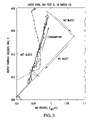
- FIG. 7 shows graphically the modification of gas mixtures in multi-chambered gas discharge lasers operating at differing duty cycles and having different multidimensional state spaces according to duty cycle according to an embodiment of the present invention
- FIG. 8 shows the data points for the beginning points only of the injections tracked in FIG. 7 , and the respective target state spaces
- FIG. 9 shows a different multidimensional state space according to an embodiment of the present invention schematically indicating a steady state operation according to an embodiment of the present invention
- FIG. 10 shows the state space of FIG. 9 schematically showing an operation where there is a need for a change in a parameter other than gas mixture, in addition to gas mixture, according to an embodiment of the present invention
- FIG. 11 shows a block diagram of a software implemented state machine according to aspects of an embodiment of the present invention.
- FIG. 12 shows a block diagram flow chart for the FIXEDOPSTATE of the state machine of FIG. 11 according to aspects of an embodiment of the present invention.
- FIG. 13 shows a block diagram flow chart for the INJECTSTATE of the state machine of FIG. 11 according to aspects of an embodiment of the present invention.
- the present invention takes into account that there are a number of possible operating states the laser system could be in, given two chambers (MO, PA) and defining several gas states, e.g., three relative gas states (Lean, Good, Rich).
- gas states e.g., three relative gas states (Lean, Good, Rich).
- “good” meaning within some pre-selected target range (which may vary over the life of the laser, e.g., as changes in the electrodes, or other effects on the discharge, cause, e.g., the charging voltage on the peaking capacitors to rise in order to maintain the desired output laser light pulse beam power requirements, which are generally dictated by the end users of the light and must be met), “lean” meaning out of range with the partial pressure low, and “rich” meaning out of range with the partial pressure high.
- Applicants then overlaid these coordinates with “gas axes” of MO [F 2 ] and PA [F 2 ], e.g., rotated by 45° as is shown in FIG. 1 .
- the system and process according to an embodiment of the present invention can then provide for a mapping from measurable quantities, e.g., Emo, HV, to a gas state (MO Lean/Good/Rich, PA Lean/Good/Rich) within one of the, e.g., nine possible combinations, including a center “target” of MOGood, PAGood, as shown in FIG. 2 .
- This mapping can then provide a basis for determining operating parameter modifications, e.g., how much to modify the gas mixture in each chamber, e.g., selecting an amount for an inject size on each chamber, including zero, at each inject, and the time for each inject, in order to drive the system toward a desired gas state.
- a two chambered system e.g., a MOPA or MOPO system.
- the utilization of, e.g., a multidimensional geometric (state-space) interpretation of the gas state of the laser and the need for and amount(s) of injection(s) required Applicants have chosen to call this the “Wheel of Fluorine,” which is indicated at 10 in FIG. 2 .
- the zones 10 a - i , of the wheel 10 provide guidance as to what the gas state currently is in both the MO and the PA, relative to the desired target gas state MOGood, PAGood state 10 a , not surprisingly the center of the bull's-eye formed by the wheel 10 .
- the rings 11 , 12 including zones 10 b - e in the inner ring 11 and 10 f - i in the outer ring 12 , of the wheel are determined by configurable parameters, and the gas state is evaluated prior to each inject.
- Table I has a set of bins/columns (five), with each bin/column containing three values, a reference MO energy, a reference voltage, and an inject frequency.
- the four internal bin boundaries, duty cycle, Emo, HV and inject frequency are Configurables and can be set empirically and may even vary over laser system life and even individually for each chamber operating life, and Table I contains representative values.
- the first two values Emo and HV can be used, e.g., just prior to each inject, e.g., to determine where the laser is on the Gas State diagram 10 , as discussed in more detail below, i.e., the zone 10 a -I in which the laser is operating.
- the third value is used, e.g., to determine the update frequency (or freshness) of the information in the bins. This can be used, e.g., to determine how the bin values are adapted over time and operating life.
- Table I replaces, e.g., voltage accounting methods used, e.g., in the applicants' employer's 5000 to 7000 laser products.
- the MO energy and voltage reference values in each duty cycle bin can provide, e.g., gas mix “anchors” which only slowly change as chamber(s) ages.
- the Gas State diagram 10 can provides, e.g., a map of the pre-inject operating condition of the laser relative to a target condition provided by the reference MO energy and voltage Table 1 above.
- Emo and burst average voltage (“BAV”) referred to herein as HV By comparing the measured values of Emo and burst average voltage (“BAV”) referred to herein as HV, just prior to starting an inject with the target values from the table, selected, e.g., by the current duty cycle, e.g., the current gas condition can be determined.
- the combination of a moderately elevated MO energy and voltage relative to the reference values, i.e., within zone 10 b would indicate a state of MO OK, PA Lean. This indicates the need for a boost injection only in the PA chamber.
- a set of configurables can be used, e.g., to geometrically determine the size of the center target ring 10 a , i.e., no boost indicated, the middle ring 11 , single chamber boost needed—MO or PA, and the outer ring 12 , dual chamber boost needed—both MO and PA. Both positive and negative boosts are allowed.
- Table I lists for the five bin boundaries, 0-15, 16-25, 26-45, 46-60 and 61-100, 5 respective reference MO energies, and 5 respective reference voltages which can, e.g., all be configurables.
- the 5 inject frequencies can, e.g., be diagnostics, which can, e.g., vary based upon actual operating conditions. Additional configurables may be required to provide flexibility in setting the geometry of the Gas State diagram 10 . In the utilization of this gas monitoring and control system, e.g., all of the following computations are done upon successful entry to an F 2 inject state.
- D ⁇ ⁇ C ⁇ ⁇ ( % ) 100 ⁇ BurstLength ( BurstLength RepRate + BurstInterval ) ⁇ 4000
- Burst Length is the number of pulses in a burst
- Burst Interval is the time between bursts
- Rep Rate is the laser burst repetition rate
- 4000 is the pulse repetition rate within a burst, e.g. in a 4 KHz repetition rate laser, and which may change from laser to laser according to its designed pulse repetition rate.
- the DC may be calculated periodically, e.g., every 30 seconds and, e.g., the most recent calculation may be used each time.
- the appropriate duty cycle bin from Table I above can be selected and, e.g., a reference Emo_ref and HVref read from the appropriate bin.
- These two values, along with the current values of Emo and HV, computed as the (BAV) can, e.g., be utilized to compute a pair of scaled errors:
- E _ MO inner E MO current - E MO ref ⁇ ⁇ ⁇ E MO inner
- E _ MO outer E MO current - E MO ref ⁇ ⁇ ⁇ E MO outer
- V _ inner V current - V ref ⁇ ⁇ ⁇ V inner
- V _ outer V current - V ref ⁇ ⁇ ⁇ V outer
- the left, “inner” column above can, e.g., define the boundary of the inner ring 10 a region in the Gas State diagram 10 , between the no boost ring 10 a region, and single chamber boost 11 region.
- the right “outer” column can, e.g., define the boundary of the outer ring, between the middle ring 11 -region one chamber boost region and the dual chamber boost region of ring 12 .
- the two ⁇ V's and two ⁇ E's that provide the scaling for the 3 gas state regions 10 a , 11 and 12 are also configurables, and may be determined empirically.
- the distance from the center of the multivariable gas state space coordinate system 10 for any given target (defined by the particular bin) and the outer boundary of the inner target region 10 a is a selected ⁇ Emo inner or a selected ⁇ V inner and the distance from the center of the multivariable gas state space coordinate system 10 for any given target (defined by the particular bin) and the outer boundary of the middle ring region 11 , in the example of the preferred embodiment, is some selected ⁇ Emo outer and some selected ⁇ V outer , which are configurables and can be selected periodically, e.g., selected empirically by experimentation, as discussed further below.
- the next step according to the illustrated embodiment of the present invention can be, e.g., to determine in which region in the diagram 10 the laser is currently operating.
- a computation may be made of the radial distance from the center scaled by the inner ring and the outer ring:
- R inner ⁇ square root over (( E MO inner ) 2 +( V inner ) 2 ) ⁇
- R outer ⁇ square root over (( E MO outer ) 2 +( V outer ) 2 ) ⁇
- [0,+1] for quadrant 10 b means that the MO is okay and the PA is lean, i.e., 0 change for the MO and an inject +1 for the PA;
- [+1,0], e.g., region 10 d means that the MO is lean and the PA is Okay, i.e., MO with +1 needs an injection and the PA at 0 needs none;
- [0, ⁇ 1] for quadrant 10 d means that the MO (0) is okay and the PA ( ⁇ 1) is rich;
- [ ⁇ 1,0] for quadrant 10 c means that the MO ( ⁇ 1) is rich and the PA (0) is okay.
- the MO is rich ( ⁇ 1) and the PA is lean (+1); quadrant 10 i , the MO is lean (+1) and the PA is lean (+1); quadrant 10 g the MO is rich ( ⁇ 1) and the PA is rich ( ⁇ 1); and quadrant 10 f the MO is lean (+1) and the PA is rich ( ⁇ 1).
- the half of the quadrant that makes each MO and PA pair in the region 10 h corresponds to the part of the pair that was not okay in the adjacent middle ring 11 region, i.e., region 10 h is MO rich and PA lean and middle region 10 e is MO rich PA okay and region 10 b is MO okay and PA lean.
- the MOF2 consumed from the current ACR and the shot count can be, e.g., a configurable determined empirically and variable over time.
- the MO and PA Boost Sizes can both be in units of kPa. This replaces previously used boost logic, which used a combination of voltage rise above reference and inject sensitivity to try to compute the amount of, e.g., PA inject to return to a target operating voltage.
- MO ACR [new] MO ACR[old]+[ MO Boost State] ⁇ [ ⁇ ACR increment]
- PA ACR [new] PA ACR[old]+[ PA Boost State] ⁇ [ ⁇ ACR increment]
- a preferred embodiment of the present invention also contemplates, e.g., changing an adaptation mechanism for determining the reference values of Emo and HV as a function of the duty cycle discussed above.
- the majority of injects are performed at high duty cycle, since the active consumption component can dominate total fluorine consumption.
- the duty cycle bin that contains the highest active duty cycle (e.g., 61-100) for a given laser will likely be used most often for injections.
- the following mechanism according to an embodiment of the present invention, is designed, e.g., to address this operational reality.
- Inject_frequency[ i , current bin] (100 ⁇ Kf )/100 ⁇ Inject_frequency[ i ⁇ 1, current bin]+ Kf 1.
- Inject_frequency[ i , all other bins] (100 ⁇ Kf )/100 ⁇ Inject_frequency[ i ⁇ 1, all other bins] 2.
- the frequency (% of injects) of the last (100/Kf) injects is tracked for use in the following adaptation step.
- the following adaptation step can, e.g., only be performed if R outer ⁇ 1, i.e., in the 10 a ring or 11 ring regions. This can, e.g., prevent a bad cycle from corrupting the reference values that anchor the system to producing a rational gas mix.
- the process can be to determine which of the following two cases apply, and respond accordingly:
- the current change is in the “highest-frequency” bin, e.g., the 46-60 bin because that is the most commonly seen duty cycle:
- the high-frequency bin is used to set the absolute level for all of the other bins. This has benefits, e.g., as chambers age, the reference voltage in the high-frequency bin will naturally rise, and it will carry all the other bins with it. Additionally, the lower frequency bins will effectively be adjusted relative to the high-frequency bin each time they are used for an injection of gas. This allows, e.g., the shape of the HV vs. DC curve to change with time.
- adaptation could, e.g., be performed only starting at the M th inject, beyond the first, where M can also be a configurable. Also, because there is a higher confidence in the gas mix early in the gas life, this adaptation process could, e.g., only be performed for the first N injects, where N can also be a configurable.
- the inject count could, e.g., be incremented at the start of each inject, and should be consistent for the entire inject.
- the previously employed voltage accounting logic has been replaced by the DC-indexed table of Table I, and Wheel o' Fluorine Gas State diagram 10 discussed above. Therefore, it may no longer be necessary to track voltage changes due to duty cycle changes. Voltage accounting, however, should still be performed, because the time spent in NewOpPoint can provide a useful injection hold-off period following a duty cycle change, and the voltage and MO energy rise may still provide some valuable information. The result of voltage accounting, however, is, according to an embodiment of the present invention no longer used to update the reference voltage, which is handled by using Table I.
- the DC-indexed table of Table I may not be used, e.g., to handle energy set point changes, which may cause changes in burst average voltage proportional to the current value of dV/dEtarget. Assuming a typical dV/dEtarget value of 20V/mJ, a 2 mJ energy target change will result in a 40V change in burst average voltage. A similar effect may be seen in Emo, and dEmo/dEtarget must also be tracked. To handle this effect, NewOpPoint state must be modified to track the approximate value of dV/dEtarget (and dE/dEmo), as follows according to an embodiment of the present invention:
- the process can be, e.g., to enter NewOpPoint, by latching the previous Etarget, Emo, and BAV (Etarget[entry], Emo[entry], and BAV[entry])
- dE target[current] ( E target[exit] ⁇ E target[entry]) i.
- dEmo [current] ( Emo [exit] ⁇ Emo [entry]) ii.
- dV [current] (BAV[exit] ⁇ BAV[entry]) iii.
- dV — dE target — dV[i ] (1 ⁇ Kd ) ⁇ dV — dE target[ i ⁇ 1 ]+Kd ⁇ dV — dE target[current] 1.
- dEmo — dE target — dV[i ] (1 ⁇ Kd ) ⁇ dEmo — dE target[ i ⁇ 1 ]+Kd ⁇ dEmo — dE target[current] 2.
- a configurable e.g., duty cycle or energy set point (average energy). It may also happen, e.g., after a new gas fill.
- the system cannot always rely on an energy control system estimate of dV/dE being available, since some end users of the laser light, e.g., for microlithography may use external energy control. For this value it is only necessary to provide a ballpark estimate of dV/dE. These two values can then, e.g., be used to adjust the current values of Emo and BAV, e.g., upon injection, e.g., by converting these values back to their equivalent values at 10 mJ.
- the system may, e.g., be operated with nominal injects of, e.g., 1.5 kPa, e.g., of F 2 (contained within_kPa of a nobel gas, e.g., neon), with boosts of, e.g., 0.5 kPa, multiplied by ⁇ 1, 0 or +1.
- the total F 2 injected, weighted by chamber—MO or PA determines the magnitude of the injection.
- the net injection vector is determined by the ratio of the size of the MO injection and the PA injection, and if either is zero than the injection occurs on the PA lean to PA rich axis in FIG. 2 or the MO lean to MO rich axis in FIG. 2 respectively.
- the system may not have equal injection nominal unit sizes, so that a unit injection of, e.g., 1.5 kPa for the PA may correlate to a 1.0 Kpa for the MO, as shown e.g., in FIG. 4 .
- FIG. 4 a shows respective changes imposed upon the multidimensional state space according to an embodiment of the present invention similar to those shown in FIG. 4 .
- the net gas state change should be a vector sum of the MO consumption and PA consumption and the HV component of the net gas state change should equal the MO and PA HV components to the net change vector.
- the system computes the current location of the gas mixture in the multi-dimensional state space and determines, e.g., that the state is in the outer ring 12 at, e.g., 10 , MO lean, PA lean (+1,+1) so that the MO and the PA both get the normal inject and in addition a +1 boost.
- the MO injection from a point on the MO lean, MO rich axis of FIG. 2 where the MO is lean toward the target of MO good ( 10 a ) is in the direction shown in FIG. 3 , and as noted above may be scaled smaller than the PA inject plus boost.
- the PA inject along the PA lean, PA rich axis in FIG. 2 from the direction of PA lean toward the target 10 a , PA good, is in the direction shown in FIG. 3 .
- the net injection vector moves the operating point toward the circled 3 in the lower left of the chart of FIG. 3 .
- the F 2 injection algorithm can be based on adaptively tracking an Active Consumption Rate (ACR) of each chamber of the laser system—MO and PA.
- ACR is the F 2 consumption rate, e.g., in kPa/Mshot, due to the number of shots having been fired, i.e., gas discharges resulting in an output laser light pulse in beam form, usually as part of a burst of pulses with some interval between bursts.
- ACR can vary, e.g., usually slowly with gas mix, chamber age, and duty cycle. Accurate ACR determinations can allow for purely shot based injections.
- An adaptation mechanism can rely on tracking the dual-chamber gas space-state of the laser, e.g., at different duty cycles.
- the gas space state on a multidimensional state-space coordinate system e.g., the two dimensional Emo (mJ) v. HV (V)
- mJ two dimensional Emo
- HV HV
- Efficiency changes due to operation at different duty cycles can be handled, e.g., by a series of gas state target regions, i.e., the “wheels,” i.e., ring regions 10 a , 11 and 12 shown in FIG. 2 .
- the duty cycle at the time of an injection can be used to determine which wheel/ring to compare the current measured gas state-space operating point against.
- “Boost logic” can be used to determine whether to perform a nominal inject to each chamber or to provide a positive or negative boost to one or both chambers.
- active consumption due to shots fired, whereby, e.g., fluorine reacts with electrode material during discharge, and forms compounds that, e.g., coat the electrodes or drift around in the laser gas until removed, e.g., by a filter, and passive consumption [kPa/hour], e.g., due to elapsed time, during which, e.g., fluorine reacts slowly with chamber walls, gas lines, imperfect seals, etc., whether shots are being fired at the time or not.
- ACR Active Consumption Rate
- PCR Passive Consumption Rate
- a consumption target may be set, e.g., for one of the chambers (e.g., the PA by default) which may be equal to a nominal inject size, e.g., if the nominal inject size is 1.2 kPa, then the PA consumption target can be set to 1.2 kPa.
- a nominal inject size e.g., if the nominal inject size is 1.2 kPa, then the PA consumption target can be set to 1.2 kPa.
- an inject may be requested by the system controller (not shown).
- the estimated amount of F 2 consumed by the other chamber may also be used to set the inject size for that chamber. For example, if the MO chamber consumes 1.35 kPa for every 1.2 kPa consumed by PA, e.g., the nominal MO inject could then be set to 1.35 at the time of the injection.
- This function of the controller is not modified according to the disclosed preferred embodiments of the present invention, and the present invention relates to supplementing this controller function of determining when and how much to make as nominal injections. Utilizing, e.g., adaptive determination of the ACR's for the chambers, MO and PA, e.g., can, in part, enable this supplementation.
- An ACR can, according to embodiments of the present invention be inferred, e.g., from the laser gas state-space of the current operating point in the gas state-space 10 , e.g., a combination of average Emo and HV (BAV), e.g., by noting where the state-space is from one inject to the next.
- BAV average Emo and HV
- ACR is adaptive, increased or decreased, depending on whether the voltage at the time of inject is higher or lower than a certain reference voltage, which reference voltage is also adapted on the basis of difference to actual voltage, e.g., at a higher time reference determination than the ACR. Therefore once the voltage reference has converged, the ACR will not change or will change very slowly, e.g., based on slowly changing passivation changes.
- a separate consumption rate can be estimated for each chamber, e.g., using the following:
- [ F 2 ] consumed ( shots ⁇ ⁇ since ⁇ ⁇ inject ) 1 , 000 , 000 ⁇ ( ACR ⁇ [ k ⁇ ⁇ Pa ] Mshot ) + ( hours ⁇ ⁇ since ⁇ ⁇ inject ) ⁇ ( PCR ⁇ [ kPa ] hour )
- Consumption results in increased average voltage to deliver the same output energy, e.g., from the PA, and consumption may also result in either increased, deceased, or unchanged MO energy, depending on the relative size of the partial derivatives in the following equation:
- ⁇ ⁇ ⁇ E MO ( ⁇ E MO ⁇ [ F 2 ] ) ⁇ ⁇ ⁇ ⁇ [ F 2 ] + ( ⁇ E MO ⁇ V ) ⁇ ⁇ ⁇ ⁇ ⁇ V
- a PA chamber injection moves the gas state space operating point for the PA in the “PA Rich” direction along the PA axis orthogonal to the MO gas state axis as shown in FIG. 2 .
- Typical consumption usually causes both MO and PA to get leaner, i.e., the gas state-space points for each moves in the HV High direction as shown in FIG. 2 .
- a higher voltage than desired or targeted is indicated as being needed to maintain output power in the output of the PA and also in the output of the MO.
- a typical injection usually causes both MO and PA to get richer, i.e., the gas state-space operating point for each chamber moves in the HV Low direction on the HV High HV Low axis as shown in FIG. 3 .
- the Wheel of Fluorine 10 can be thought of as a sort of “compass” which can indicate which direction the gas state will go for a given change in gas mix and also which direction it needs to go from the current operating point to get to or near a selected target, e.g., 10 a in FIG. 2 .
- the system and method according to an embodiment of the present invention employs laser operating data, e.g., gas consumption and the injection cycle.
- the Wheel of Fluorine “target” can provide, e.g., necessary information useful in adjusting the ACR estimate. Injection is attempted in an amount matching the consumption believed to have occurred since the last injection. That is, e.g., a 1.2 kPa inject when the estimate is that consumption was 1.2 kPa.
- the Wheel of Fluorine can also be used as a “target”:
- the Wheel of Fluorine “target,” e.g., provides the necessary information to adjust the system ACR estimate, e.g., as follows:
- the duty cycle (DC) operating space is divided up into five bins, each with its own target center, i.e., in the illustrative example, Emo and HV, with, in the example, default bins (% DC): [0 ⁇ 15, 16 ⁇ 25, 26 ⁇ 45, 46 ⁇ 60, 61 ⁇ 100.
- the current DC is used to select the appropriate bin, and that bin's stored Emo and HV are used as the Wheel of Fluorine target center to determine whether any ACR adjustments or boosts are necessary.
- These bin values are slowly adapted, essentially low pass filtering, to allow for increases in nominal HV as the chambers age.
- FIG. 6 shows the results of a routine gas test over about 1B pulses.
- the plot is of Emo and HV vs. Shot Count.
- the data point markers between about 0 and 0.3B shots and between about 0.6B and 0.9B shots (excepting those at about 0.75B to 0.8B shots) are a one-duty cycle, e.g., 38%.
- the data point markers between about 0.3B and 0.6B are at another duty cycle, e.g., 75%.
- the data point markers between about 0.75B and 0.8B and between about 0.9B and 1.0B are at a third duty cycle, e.g., about 25%. It can be seen from FIG.
- each of the duty cycle groupings tend to stay within a defined band of both Emo and V, e.g., for the 38% duty cycle between about 905-915 volts and about 0.83-0.98 Emo, and for the 75% duty cycle groups between about 890-905 volts and about 0.88-1.3 Emo, and the about 25% duty cycle between about 910-923 volts and about 0.88 and 0.98 Emo, with some variations outside of these general bands.
- FIG. 7 shows the results of a representative routine gas test for HV vs. Emo, indicating operating within bins 25-45% and 60-100%.
- the numbered balls indicate the gas state at the start of each inject.
- the target and inner ring for each of the bins 25%-45% and 60%-100% are also shown.
- FIG. 8 which is the same data as shown in FIG. 7 with only the inject start points shown, the data tends to be clustered together by duty cycle, on the two different duty cycle target wheels also shown in FIGS. 7 and 8 , and tends to group in the target 10 a or at least the inner ring 11 .
- the present invention there are also used two measured parameters to estimate a 2 variable laser state for an F 2 injection algorithm.
- the parameters contrary to earlier systems that may have used output bandwidth, as measured in a spectral analysis module (“SAM”), the state of the laser is defined by 2 state variables, namely F 2 concentration and wavefront distortion.
- SAM spectral analysis module
- the laser operating state operating point in a multidimensional state-space coordinate system can be controlled, e.g., by two different actuators, e.g., the F2 concentration, which may be done in the manner described above, and control of the wavefront, e.g., by adjustments made, e.g., by an active beam control device (“BCD”), which may be, e.g., a grating curvature apparatus in, e.g., a line narrowing module (“LNM”).
- BCD active beam control device
- LNM line narrowing module
- the system according to the present embodiment of the invention also includes a wheel of zones.
- the horizontal axis of Emo replaced by ⁇ , as indicated by the electrical output of a wavemeter sampling the laser output light pulse beam out of, e.g., the PA, and the PA gas state axis is replaced by the wavefront axis.
- This may be, e.g., measured by the wavemeter, e.g., as a bandwidth of the laser PA output, e.g., as a full width half max (“FWHM”) measurement or other percentage of the peak of the spectrum, e.g., FWX % M, or a measure of the integrated energy within the spectrum on either side of the peak, e.g., 95%, i.e., E95, or some other integrated total energy, e.g., EX %.
- the wavefront axis represents relative changes in ⁇ that are not related to F 2 concentration changes.
- the MO axis has been replaced simply by an F 2 axis. This may be thought of as rotating the wheel chart shown in FIGS.
- the state variables are approximately rotated by 45° with respect to the measurement axes for appropriate choice of scaling factors, the scaling being determined empirically by experimentation, e.g., ⁇ and HV.
- Adjustments are made to the F 2 concentration, in both the MO or PA according to the above description. This may be thought of as the MO and PA changes projected onto one axis, which is the single F 2 axis in FIGS. 9 and 10 .
- F 2 injects to correct the component of the error parallel to the F 2 axis as noted above.
- the system can also, e.g., use BCD adjustments to correct the component of the error parallel to the wavefront axis, i.e., high wavefront curvature to low wavefront curvature.
- a steady-state may be characterized by the following conditions:
- the laser operating state moves in the multidimensional state space along the F 2 axis.
- F 2 Injects can occur along the semi-axis, by definition of that axis F 2 lean to F 2 rich.
- the laser operating state moves in the multidimensional state-space back to the reference point, following the same semi-axis (F 2 rich to F 2 lean, as shown by the arrow in FIG. 10 .
- the inject can be requested when the inject is back at the reference point region 10 a ′. No distortion of the wavefront occurs in steady-state, so that there is no component of the error which is parallel to the wavefront axis.
- the laser state before the inject will still lie along the F 2 semi-axis but it may over or under-shoot.
- Both ACR and Vref will, e.g., adapt to their true value using a mechanism similar to that in the LoFi algorithm, which was an earlier version of a Line of Fluorine for a single chamber laser.
- the boost logic e.g., can also be unchanged from that noted above with respect to the Wheel of Fluorine algorithm.
- the error used in the adaptation and boost equation can be different, i.e., it can be based on the error between the gas operating state as indicated in FIG. 10 before an inject and a reference state projected on the F 2 axis, e.g., as indicated by the F 2 injection arrow in FIG. 10 , e.g., with no distortion of the wavefront assumed in this example.
- a BCD correction can be applied. This adjustment can occur in closed loop before the inject between the 10K average of the bandwidth and the BCD position.
- the algorithm can be selected to find a minimum of the wavefront error. This relates to shifting the generally parabolic relationship of the BW by changes in curvature, e.g., of the grating, to a different minimum point by the change in the curvature of the grating, e.g., to adapt to the changing wavefront.
- the bins may be arranged in other than the ranges noted, e.g., by a specific duty cycle and selection o f the bin may be made by proximity of the calculated duty cycle to the possible choices identifying each bin or alternatively interpolation may be done between the two adjacent closest bin according to the proximity of the actual duty cycle to the value identifying each such bin. It will also be understood that in three or higher dimensions the “rings” of the wheel will be spheres or such other multidimensional state space structures as are appropriate.
- the number of rings/spheres or other multidimensional region-defining shapes may represent unique curves or surfaces having, e.g., a defined vector distance from the origin, and/or may represent many more that just the several boost values of the presently preferred embodiments and/or be able to be interpolated between adjacent regions to arrive at what approaches a continuum of boost values determined from the position of the operating point in the state-space coordinate system, and region as used in the specification of the present application is intended to encompass regions in a state-space coordinate system that may, e.g., lie in a three dimensional coordinate system but not have three dimensions, e.g., the pints on the surface of a sphere.
- the parameters used to define a state of the laser operation may be F 2 concentration as determined from HV and bandwidth, as shown in FIGS. 9 and 10 on, respectively, the vertical and horizontal axes respectively and for the case where the determination of the F 2 to be injected is not also a function of the wavefront being out of steady state.
- the laser operating state operating point in the multidimensional state-space coordinate system, including HV and ⁇ can be controlled, e.g., by only the F2 concentration, which may be done in a manner similar to that described above, and control of the wavefront.
- the system according to the present embodiment of the invention also includes a wheel of zones.
- the horizontal axis of Emo replaced by ⁇ , as indicated by the electrical output of a wavemeter sampling the final laser output light pulse beam and the PA gas state axis is replaced by the wavefront axis.
- This may be, e.g., measured by the wavemeter, e.g., as a bandwidth of the laser output, e.g., as a full width half max (“FWHM”) measurement.
- FWHM full width half max
- the wavefront axis represents relative changes in ⁇ that are not related to F 2 concentration changes, i.e., those along the F 2 axis, i.e., from F 2 rich to F 2 lean, which axis replaces the MO axis.
- the state variables e.g., the F 2 axis is approximately rotated by 45° with respect to the measurement axes for appropriate choice of scaling factors, here HV and ⁇ , the scaling being-determined empirically by experimentation, e.g., using ⁇ and HV.
- a steady-state may be characterized by the following conditions:
- the laser operating state moves in the multidimensional state space along the F 2 axis.
- F 2 Injects can occur along the semi-axis, by definition of that axis F 2 lean to F 2 rich.
- the laser operating state moves in the multidimensional state-space back to the reference point, following the same semi-axis (F 2 rich to F 2 lean, as shown by the arrow in FIG. 10 ), and as with the case of Emo and HV noted above, tracked by changes in HV and ⁇ .
- the inject can be requested when the inject is back at the reference point region 10 a ′. No distortion of the wavefront occurs in steady-state, so that there is no component of the error which is parallel to the wavefront axis.
- the laser state before the inject will still lie along the F 2 semi-axis but it may over or under-shoot, as is shown in FIG. 10 , e.g., for the case where the BCD adjust is not present in the formulation.
- Both ACR and Vref will, e.g., adapt to their true value using a mechanism similar to that in the LoFi algorithm, which was an earlier version of a Line of Fluorine for a single chamber laser using only the change in voltage and therefore a one dimensional state space.
- the boost logic e.g., can also be unchanged from that noted above with respect to the Wheel of Fluorine algorithm.
- the error used in the adaptation and boost equation can be different, i.e., it can be based on the error between the gas operating state as indicated in FIG. 10 before an inject and a reference state projected on the F 2 axis, e.g., as indicated by the F 2 injection arrow in FIG. 10 , e.g., with no distortion of the wavefront assumed in this example.
- the present invention takes into account that there are a number of possible operating states the laser system could be in defining several gas states, e.g., three relative gas states (Lean, Good, Rich).
- HV and BW are believed to be the most reliable pair. It is possible according to aspects of an embodiment of the present invention to arrange the variables for purposes of consideration into, e.g., a geometric interpretation of the results, e.g., the utilization of a multidimensional state space.
- Applicants then overlaid these coordinates a “gas axis” of the gas discharge laser, e.g., rotated by 45° as is shown, e.g., in FIG. 9 .
- the system and process according to an embodiment of the present invention can then provide for a mapping from measurable quantities, e.g., BW and HV, to a gas state (Lean, Good, Rich, Very Lean, Very Rich) within one of the possible combinations, including a center “target”, as shown, e.g., in FIGS. 9 and 10 .
- This mapping can then provide a basis for determining operating parameter modifications, e.g., how much to modify the gas mixture, e.g., selecting an amount for an inject size including zero, at each inject, and/or the time for each inject, in order to drive the system toward a desired gas state.
- a simple mathematical framework for understanding the need for and results of an inject upon performance behavior.
- zone 20 F 2 Very Lean the outer two dimensional half-ring shaped region along the rotated F 2 consumption axis in the F 2 lean direction
- zone 28 F 2 Very Rich (the outer two dimensional half-ring shaped region along the rotated F 2 consumption axis in the F 2 rich direction) zone 22
- F 2 Lean the inner two dimensional half-ring shaped region along the F 2 consumption axis in the lean direction
- zone 26 F 2 Rich (the inner two dimensional half-ring shaped region along the F 2 consumption axis in the rich direction)
- zone 24 F 2 good the circular two dimensional region surrounding the origin of the coordinate system.
- the position of the operating point of the laser based on the values of, e.g., HV and ⁇ (BW) and the algorithm described below, in the coordinate system 10 provides guidance as to what the gas state currently is.
- the inner circle 24 and rings 30 , 32 may be determined by configurable parameters, and the gas state may be evaluated prior to each inject.
- the configurable parameters may be optimized, e.g., empirically, by the user based, e.g., on measured performance parameters for a particular class of laser (ArF, KrF, etc.) and configuration of such a laser in such a class of lasers, for which a control system according to aspects of the present invention, including adaptive fluorine injections (“AFI”).
- AFI adaptive fluorine injections
- the first is a look-up table indexed by duty cycle, as shown in Table II.
- Table II has a set of bins/columns (, e.g., five), with each bin/column containing three values, a reference BW, a reference voltage, and an inject frequency.
- the four internal bin boundaries, duty cycle, BW, HV and inject frequency may be used.
- Table II contains representative values.
- the value for duty cycle may extend to 140% since energy duty cycle, as defined below, may be employed as opposed to the shot count duty cycle discussed above.
- the first two values BW and HV can be used, e.g., just prior to each inject, e.g., to determine where the laser is on the Gas State diagram 10 ′ as shown, e.g., in FIGS. 9 and 10 , as discussed in more detail below, i.e., the zone 20 - 28 in which the laser is operating.
- the third value may be used, e.g., to determine the update frequency (or freshness) of the information in the bins. This can be used, e.g., to determine how the bin values are adapted over time and operating life.
- the BW and voltage reference values in each duty cycle bin can provide, e.g., gas mix “anchors” which only slowly change as the chamber ages.
- the Gas State diagram 10 ′ can provide, e.g., a map of the pre-inject operating condition of the laser relative to a target condition provided by the reference BW and HV, e.g., as shown in Table II above.
- BAV burst average voltage
- HV X-shot rolling average voltage
- the combination of a moderately elevated BW and voltage relative to the reference values and the ratio of ⁇ BW to ⁇ HV e.g., above the BW (High, Low) rotated axis 50 , i.e., to the right of the vertical HV axis and above the horizontal BW axis, and above or below the BW rotated axis 52 that is orthogonal to the F 2 consumption axis 50 , i.e., either within that portion of zone 22 or that portion of zone 26 , would indicate a state of the gas consumption since the last inject that has resulted in the F 2 concentration being on the Rich or Lean side of the rotated bandwidth axis 52 , but not in the Very Lean zone 20 or the Very Lean zone 28 .
- the laser state operating position being in the Very Lean zone 20 or the Very Rich Zone 28 might result, e.g., from a slightly more elevated HV error and/or BW error from the origin of the coordinate system and also in the upper right quadrant of the coordinate system 10 ′.
- HV below a selected reference value and/or BW below a selected reference value or a combination of one or the other can place the laser operating state in one of the other three quadrants of the coordinate system 10 ′ and also the ratio of ⁇ BW to ⁇ HV can determine if the position if in the F 2 rich or F 2 Lean portions of the AFI wheel.
- This positioning of the operating point, e.g., in zone 22 indicates the need for a boost injection of some amount over the normal injection since the position of the operating point indicates the F 2 concentration in the laser is in the Lean zone 22 .
- a set of configurables can be used, e.g., to geometrically determine the size of the center target ring comprising zones 22 and 26 , i.e., a first level of boost indicated, and the outer ring comprising zones 20 , 28 with a higher level of boost needed, and the sizes of the boosts. Both positive and negative boosts are allowed, with the former occurring when the operating point is in the zones 20 and 22 and the latter when the operating point is in the zones 26 , 28 .
- the determination of the boost amount may be made, e.g., from consideration of the values of R outer and R inner , such that, when
- Inject size may be, e.g., some preselected inject amount, that may, e.g., change over laser life.
- the F 2 estimated consumption since last inject and therefore the nominal inject amount, from the current ACR and the shot count.
- the ACR being a configurable laser to laser at start of life and varying over life according to updating, e.g., as discussed below.
- F 2 consumed by other methods, e.g., real time F 2 measurements.
- the normal inject target injection amount may also take into consideration time since the last inject and the Passive Consumption Rate (“PCR”) times the elapsed time, though in normal operation and absent a preceding long off time, the ACR will effectively dominate the estimate of consumption since the last inject.
- PCR Passive Consumption Rate
- the estimated consumption may be calculated by adding (ACR ⁇ shot count since last injection)+(PCR ⁇ elapsed time since last injection).
- ACR may be updated, e.g., by creating a new ACR for the next injection cycle ACR N that is equal to the ACR for the current (Oust completed) inject cycle (“ACR N-1 ”) plus some constant times (a selected ACR increment) multiplied by, e.g., the value of the boost state computed for the just completed inject cycle.
- the inject target size may be updated after each injection according to the formula Inject size for the Nth inject is equal to the Inject size for the Nth-1 inject times some constant times the Inject Size for the last inject over some constant, e.g., 2 times the boost state for the Nth-1 inject.
- the Boost Size can be in units of kPa.
- a preferred embodiment of the present invention also contemplates, e.g., changing an adaptation mechanism for determining the reference values of BW and HV as a function of the duty cycle discussed above.
- the majority of injects are performed at high duty cycle, since the active consumption component can dominate total fluorine consumption.
- the duty cycle bin that contains the highest active duty cycle e.g., 61-100
- This operational reality can be addressed as discussed above, and in this way, the frequency (% of injects) of the last (100/Kf) injects is tracked for possible use in the following adaptation step described above, only for BW and HV rather than E MO and HV.
- BW error BW current ⁇ BW ref
- V error V urrent ⁇ V ref
- the process may then be to determine which of the following two cases apply, and respond accordingly:
- the current change is in the “highest-frequency” bin, e.g., the 46-60 bin because that is the most commonly seen duty cycle:
- BW ref [ i , current DC only] BW ref [ i ⁇ 1, current DC]+Kr ⁇ BW error a.
- V ref [ i , current DC only] V ref [ i ⁇ 1, current DC]+Kr ⁇ V error b.
- the high-frequency bin is used to set the absolute level for all of the other bins. This has benefits, e.g., as the laser chamber ages, the reference voltage in the high-frequency bin will naturally rise, and it will carry all the other bins with it. Additionally, the lower frequency bins will effectively be adjusted relative to the high-frequency bin each time they are used for an injection of gas. This allows, e.g., the shape of the HV vs. DC curve to change with time.
- adaptation could, e.g., be performed only starting at the M th inject, beyond the first, where M can also be a configurable. Also, because there is a higher confidence in the gas mix early in the gas life, this adaptation process could, e.g., only be performed for the first N injects, where N can also be a configurable. These two conditions reduce to: If(this_inject ⁇ M )&(this_inject ⁇ N )) ⁇ Do Adaptation ⁇ ; Else ⁇ Skip Adaptation ⁇ .
- the optimum settings for M and N may be part of the overall algorithm according to aspects of an embodiment of the present invention.
- the software may transition into New Op Point for a time, e.g., if an energy change is detected (based upon 10K average energy), and may also compensate the measured voltage based upon the actual energy and dE/dV at the time of an inject decision.
- dV/dE energy control system estimate of dV/dE being available, since some end users of the laser light, e.g., for microlithography, may use external energy control. For this value it is only necessary to provide an approximate value of dV/dE (dV/dE nominal). These two values can then, e.g., be used to adjust the current values of BW and BAV, e.g., upon injection, e.g., by converting these values back to their equivalent values at 10 mJ.
- the F 2 injection algorithm can adaptively track an Active Consumption Rate (ACR) of the laser system.
- ACR is the F 2 consumption rate, e.g., in kPa/Mshot, due to the number of shots having been fired, i.e., gas discharges resulting in an output laser light pulse.
- ACR can vary, e.g., usually slowly with gas mix, chamber age, and duty cycle. Accurate ACR determinations can allow for purely shot based injections. An adaptation mechanism can rely on tracking of the laser, e.g., at different duty cycles.
- Efficiency changes due to operation at different duty cycles can be handled, e.g., by a series of gas state target regions, i.e., the “wheels,” i.e., ring regions 20 - 28 shown, e.g., in FIG. 9 .
- the duty cycle at the time of an injection can be used to determine which wheel/ring to compare the current measured gas state-space operating point against.
- “Boost logic” can be used to determine what to inject into the laser.
- active consumption due to shots fired, whereby, e.g., fluorine reacts with electrode material during discharge, and forms compounds that, e.g., coat the electrodes or drift around in the laser gas until removed, e.g., by a filter, and passive consumption [kPa/hour], e.g., due to elapsed time, during which, e.g., fluorine reacts slowly with chamber walls, gas lines, imperfect seals, etc., whether shots are being fired at the time or not.
- ACR Active Consumption Rate
- PCR Passive Consumption Rate
- a consumption target may be set, e.g., which may be equal to a nominal inject size, e.g., if the nominal inject size is 1.2 kPa, then the consumption target can be set to 1.2 kPa.
- a nominal inject size e.g., if the nominal inject size is 1.2 kPa, then the consumption target can be set to 1.2 kPa.
- an inject may be requested by the system controller (not shown).
- Utilizing, e.g., adaptive determination of the ACR's for the laser can, in part, enable this supplementation.
- An ACR can, according to embodiments of the present invention be inferred, e.g., from the laser gas state-space of the current operating point in the gas state-space 10 ′, e.g., a combination of average BW and HV, e.g., by noting where the state-space is from one inject to the next.
- ACR is adaptive, increased or decreased, depending on whether the voltage at the time of inject is higher or lower than a certain reference voltage, which reference voltage is also adapted on the basis of difference to actual voltage, e.g., at a higher time reference determination than the ACR. Therefore once the voltage reference has converged, the ACR will not change or will change very slowly, e.g., based on slowly changing passivation changes.
- a consumption rate can be estimated for the laser chamber, e.g., using the following:
- [ F 2 ] consumed ( shots ⁇ ⁇ since ⁇ ⁇ inject ) 1 , 000 , 000 ⁇ ( ACR ⁇ [ k ⁇ ⁇ Pa ] Mshot ) + ( hours ⁇ ⁇ since ⁇ ⁇ inject ) ⁇ ( PCR ⁇ [ kPa ] hour )
- ⁇ ⁇ ⁇ E ( ⁇ E ⁇ [ F 2 ] ) ⁇ ⁇ ⁇ ⁇ [ F 2 ] + ( ⁇ E ⁇ V ) ⁇ ⁇ ⁇ ⁇ ⁇ V
- Fluorine consumption generally causes the chamber move from Rich to Lean on the consumption axis, i.e., get leaner, i.e., the gas state-space point moves in the HV High direction as shown, e.g., in FIG. 9 .
- a higher voltage than desired or targeted is indicated as being needed to maintain output power in the output of the laser.
- a typical injection causes the laser to get richer, i.e., the gas state-space operating point moves in the HV Low direction on the HV axis as shown in FIG. 9 .
- the gas state space can also be used as a “target”:
- the F 2 gas injection control system may be understood to operate to first perform an Adaptive Fluorine Injection (“AFI”) software initialization, then to compute duty cycle and then to execute an AFI state machine.
- a software initialization may occur, e.g., because new software is loaded on the laser or if there is a major change to the laser operating conditions, e.g., installing or servicing certain laser sub-systems, e.g., the chamber, line narrowing package, etc. of after performing a system realignment.
- the operator may then reload the software, perform a gas refill, set a configurable representing an initial reference voltage (“RefVInit”) to zero, re-boot the laser (i.e., power down and then up), during which both the “auto_injection” and “paddle enable” may need to be “enabled” from the “Gas Mode” button on the paddle.
- the operator may then set the laser to fire, e.g., in a selflock firing mode, 75% DC, internal energy mode, and with a nominal energy target.
- the laser may then be fired, e.g., for >10 minutes in this condition, after which the operator will need to verify that the RefVInit configurable has been changed by the software to 1.
- the reference duty cycle bins (“updatedcb”) may be stored in memory, e.g., a non-volatile RAMNVRAM, and may be initialized during AFI software initialization, e.g., using the nominal duty cycle bin values and existing laser conditions and parameters.
- the bins may be used to obtain the duty cycle bin and/or energy duty cycle bin indices [bin i and i′] corresponding to the respective current duty cycle.
- V 10KAverage and BW 10KAverage may be evaluated at the end of an initialization period.
- BW ref [bin x ] ( BW nominal [bin x ] ⁇ delta BW ) ⁇ ( BW _Scale/2), where BW 13 Scale is a configurable similar in utilization to Vlt _Scale.
- V ref and BW ref may also play a part in the setting of the size of the target circules, i.e., R inner and R outer , as discussed below.
- the configurable RefVInit may be set to 1 to indicate successful AFI software initialization.
- the software may issue a warning (“DC not high enough”), if, e.g., after a certain time period, e.g., at the 5 minute mark of the initialization routine, the duty cycle value is less than 50%.
- the software may issue an error signal (“F2 init failed”), if after a certain period of time, e.g., at the 10 minute mark of the initialization routine, the duty cycle value is less than 50% or a REFILL_REQ bit has been set. In such an event, the laser state may be dropped to STANDBY.
- the AFI state may be stored in memory.
- the AFI state starts at the NEWOPSTATE when the software is installed, which serves simply to allow sufficient time after an operation change for the gas state to settle.
- the AFI state may then transition from NEWOPSTATE to FIXEDOPSTATE if either:
- VoltScale and BWScale may be range-bound, e.g., VoltScale may be range-bound for various different laser configurations, e.g., for lasers of the 7XXX series of lasers sold by applicants assignee, e.g.,
- BW_Scale may be range-bound, e.g., to be between 2 and 10 pm.
- Volt_Norm is a configurable set from 0-100 as a weighting factor for changing R inner and R outer .
- the software may then compute the Boost State, e.g., according to the values in Table III:
- the Boost State diagnostic values e.g., R inner , R outer , F2error, BWerror, and Boost State may be stored in memory.
- ACR Active Consumption Rate
- gain factor may vary from laser to laser, e.g., as shown in Table IV:
- ACR value is not changed.
- the software may then perform, e.g., duty cycle bin adaptation, whereby new bin values may be computed and saved in a temporary bin table in the FIXEDOPSTATE, while the reference duty cycle bins may be updated in INJECTSTATE, e.g., as shown in FIGS. 11 and 12 .
- the inject frequency values may be modified according to the following:
- the voltage and BW values may be modified according to the following, which may be computed, e.g., only if the internal inject counter value is between NInjStrt (Inject # minimum to start adaptation) and NInjStop (Inject # maximum to stop adaptation).
- Vcurrent is the “energy compensated operating voltage”.
- V ref [bin i] V ref [bin i ]+( V error*0.1)
- BW ref [bin i′] BW ref [bin i ′]+( BW error*0.1)
- the software may then update Inject Size according to the following:
- Inject Size F 2 Consumed (the calculated estimate of consumption as noted above)+(Boost State INJ *F 2 Target), in which event, if (Inject Size) ⁇ 0, then Inject Size is set to equal 0. Also stored is the value for the cumulated sum of inject sizes between the two preceding gas refills.
- the actual injection made at the occurrence of each inject opportunity may be a positive value or ⁇ 0, depending upon the values of F 2 Consumed, Boost State INJ ( ⁇ 1, ⁇ 2, 0) and F 2 Target, the target inject size, such that, e.g., if the F 2 Consumed value is 1 and the F 2 Target is set to 1, and the BoostState INJ is determined to be ⁇ 1 or ⁇ 2, then the Inject Size would be negative and no inject would occur, of if, e.g., the F 2 Consumed value is 1 and the F 2 Target is set to 1, and the BoostState INJ is determined to be ⁇ 1, then the Inject Size would be 0 and no inject would occur.
- the following parameters shown in Table VI may be set as configurables and used by the F 2 gas injection control software, which may be initially set to selected values and in some cases updated during laser operation, as appropriate. They may be stored in memory in the configurable ID locations noted.
- FIG. 11 There is shown an example of an F 2 control system state machine 200 according to aspects of an embodiment of the present invention.
- the state machine can be seen to have, e.g., three states of operation, NEWOPSTATE 202 , FIXEDOPSTATE 204 and INJECTSTATE 206 .
- the NEWOPSTATE may be entered from the FIXEDOPSTATE when significant changes occur in laser operation, e.g., when the regular duty cycle changes by, e.g., >10% or the Average Energy for the last 10K shots changes with respect to by some selected threshold.
- the laser F 2 inject control system continually monitors in decision block 210 b, e.g., every second, whether the value of F 2 Consumed exceeds some selected threshold value, e.g., F 2 Target.
- a flag (EnergySetPoint_flag) has been set indicating that Average Energy over the last 10K shots has changed from its present value by, e.g., >20 ⁇ J, indicating a relatively large change in the current value of E, or a flag (dutycyclechange_flag) has been set indicating that the duty cycle has changed by a selected amount, e.g., 0%, evaluated, e.g., every minute.
- the software can also determine in block 210 whether to transition from the FIXEDOPSTATE to INJECT STATE, if F 2 Consumed is >F 2 Target.
- the software may in block 214 , e.g., increment an internal inject counter (which is also reset to zero after each gas refill), and if DutyCycleZero_flag is not set, i.e., the laser is in operation, the software may, e.g., determine the Boost State ACR , and update ACR, and compute new values for the reference duty cycle bin of Table II as discussed above, and also update BW ref , INJFREQ, INJ BIN, and V REF and then transition into the INJECTSTATE 206 .
- the F 2 injection control software may determine in block 220 if the inject has been completed, and if not then the software may determine in block 222 whether an injection is in progress. If not then in block 224 the software periodically, e.g., every minute may determine if the DutyCycleZero_flag is set and if not then determine the Boost State INJ , and if so then set the Boost Stater INJ to 0. The software will also update the Inject Size. The software then moves to decision box 230 where it determines whether or not the inject size is equal to zero. If yes, then the software in block 323 commands no inject and if not, then the software in block 234 commands the initiation of an inject request according to some selected inject amount and the value of the boost amount.
- the software moves to block 240 the same way that it would if in decision block 220 it was determined that the inject had been completed and subsequently in block 242 the value of Inject Shots since last inject is set to zero and the value of Injects since last refill is set to 1, which may later then be incremented by 1 for each inject, before moving to block 240 .
- the value of Inject Hours is set to zero and the inject shot counter is set to zero and Inject shots is set to zero.
- F 2 Consumed will also be reset to zero since Inject Hours and Inject Shots are reset to zero and both ACR*Inject Shots and PCR*Inject Hours will both therefore be 0 initially.
- the software will copy the computed values from the temporary bin table to the reference duty cycle bins, e.g., Table II. The software will then transition to FIXEDOPSTATE.
- the bins may be arranged in other than the ranges noted, e.g., by a specific duty cycle and selection o f the bin may be made by proximity of the calculated duty cycle to the possible choices identifying each bin or alternatively interpolation may be done between the two adjacent closest bin according to the proximity of the actual duty cycle to the value identifying each such bin. It will also be understood that in three or higher dimensions the “rings” of the wheel will be spheres or such other multidimensional state space structures as are appropriate.
- the number of rings/spheres or other multidimensional region-defining shapes may represent unique curves or surfaces having, e.g., a defined vector distance from the origin, and/or may represent many more that just the several boost values of the presently preferred embodiments and/or be able to be interpolated between adjacent regions to arrive at what approaches a continuum of boost values determined from the position of the operating point in the state-space coordinate system, and region as used in the specification of the present application is intended to encompass regions in a state-space coordinate system that may, e.g., lie in a three dimensional coordinate system but not have three dimensions, e.g., the pints on the surface of a sphere.
- the injections of a selected amount of fluorine gas including, e.g., and ACR with or without plus or minus boosts may be made in any fashion understood in the art, e.g., fluorine gas alone or fluorine and a buffer gas or fluorine and a buffer gas and noble gas and may be measured in any suitable way known in the art, e.g., in kPa, partial pressure, molecular content and may, e.g., account for the temperature and pressure of the gas in the chamber at or around the time of the gas replenishment injection of fluorine.
Abstract
Description
| TABLE I | ||
| Duty Cycle (%) | ||
| 0-15 | 16-25 | 26-45 | 46-60 | 61-100 | ||
| MO Energy (mJ) ref | 0.95 | 1.01 | 1.07 | 1.15 | 1.2 |
| Voltage (V) ref | 960 | 940 | 925 | 910 | 900 |
| Inject Frequency (%) | 5 | 10 | 20 | 30 | 35 |
where Burst Length is the number of pulses in a burst, Burst Interval is the time between bursts, Rep Rate is the laser burst repetition rate, and 4000 is the pulse repetition rate within a burst, e.g. in a 4 KHz repetition rate laser, and which may change from laser to laser according to its designed pulse repetition rate. For example the DC may be calculated periodically, e.g., every 30 seconds and, e.g., the most recent calculation may be used each time.
R inner=√{square root over ((
There are, e.g., then three cases to consider:
- 1. (Rinner<1), i.e., within the
center circle region 10 a, where no boost is necessary. In the event this is the case, then, e.g., the next two considerations may be skipped. - 2. (Rinner>1) & (Router<1), i.e., in the
middle region 11, where a single chamber boost is necessary. In the event that this is the case, then, e.g., the process may be to compute an angle to determine which quadrant in the state space the operating point is in, e.g., ∠R=a tan 2(V inner, ĒMOinner ), from −π to +π, and to represent a boost state by a pair, i.e., MO Boost, PA Boost, where the boost value can be, e.g., one of (−1, 0, +1). The process can then be, e.g., to determine which of four possible cases is true, i.e.:
π/2>∠R>0: 1st quadrant 10b [0, +1] i.
π>∠R>π/2: 2nd quadrant 10e [+1, 0] ii.
−π/2>∠R>−π: 3re quadrant 10d [0, −1] iii.
0>∠R>−π/2: 4th quadrant 10c [−1, 0] iv.
- 3. (Router>1), i.e., the
outer ring 12 region applies, which can mean, e.g., boosts are required to both chambers, in which event, e.g., the process may be to compute an angle to determine which quadrant of the two dimensional state space the operating point is in, by ∠R=a tan 2(V outer, ĒMOouter ), from −π to +π, and to represent the boost state, e.g., by a pair, e.g., MO Boost, PA Boost, where the boost value can be one of (−1, 0, +1), and then, e.g., to determine which of four possible cases is true for the rotated quadrants (45° relative to the quadrants considered above relating to theinner ring 11 region):
π/4>∠R>−π/4: 1st quadrant 10h [−1, +1] v.
3π/4>∠R>π/4: 2nd quadrant 10i [+1, +1] vi.
−π/4>∠R>−3π/4: 3rd quadrant 10g [−1, −1] vii.
Otherwise: 4th quadrant 10f [+1, −1] viii.
MO Inject Size=MOF2consumed+[MO Boost State]×[MO Boost Size]
PA Inject Size=PAnominalInject+[PA Boost State]×[PA Boost Size]
MO ACR [new]=MO ACR[old]+[MO Boost State]×[ΔACR increment]
PA ACR [new]=PA ACR[old]+[PA Boost State]×[ΔACR increment]
Inject_frequency[i, current bin]=(100−Kf)/100×Inject_frequency[i−1, current bin]+
Inject_frequency[i, all other bins]=(100−Kf)/100×Inject_frequency[i−1, all other bins] 2.
Eerror=Ecurrent−Eref
Verror=Vurrent−Vref
Eref [i, every DC bin]=Eref [i−1, every DC]+Kr×Eerror a.
Vref [i, every DC bin]=Vref [i−1, every DC]+Kr×Verror b.
Eref [i, current DC only]=Eref [i−1, current DC]+Kr×Eerror a.
Vref [i, current DC only]=Vref [i−1, current DC]+Kr×Verror b.
If(this_inject>=M)&(this_inject<=N)){Do Adaptation};
Else {Skip Adaptation};
dEtarget[current]=(Etarget[exit]−Etarget[entry]) i.
dEmo[current]=(Emo[exit]−Emo[entry]) ii.
dV[current]=(BAV[exit]−BAV[entry]) iii.
dV — dEtarget[current]=dV[current]/dEtarget[current] 1.
Emo — dEtarget[current]=dEmo[current]/dEtarget[current] 2.
dV — dEtarget— dV[i]=(1−Kd)×dV — dEtarget[i−1]+Kd×dV — dEtarget[current] 1.
dEmo — dEtarget— dV[i]=(1−Kd)×dEmo — dEtarget[i−1]+Kd×dEmo — dEtarget[current] 2.
Emo[current]=Emo[current]−(Etarget−10)×dEmo/
V[current]=V[current]−(Etarget−10)×dV/
-
- a. starting at a
gas state 1 in a circle indicated inFIG. 5 , i.e., at the target MO good, Pa good, the controller can, e.g., perform an MO inject, which, e.g., puts thesystem gas state 2 in the circle as shown inFIG. 5 , and then, e.g., follow this with a PA inject to get tostate 3 in a circle shown inFIG. 5 ; - b. bs the laser fires, the gas state will move in the “Lean” direction for both chambers, but could wind up at 4 a, 4 b or 4 c as shown in the circles in
FIG. 5 , (or anywhere else) - c. if the ACR estimates were correct, after an injection, the system should have arrived at the target in 10 a, i.e., the point indicated by 1 in a circle in
FIG. 5 ;
- a. starting at a
-
- a. by definition, the system can, e.g., try to inject as much as the system believes has been consumed, e.g., since the last inject, i.e., a 1.2 kPa inject when the estimate is that is what was consumed, i.e., to point 4 b;
- b. if, for example, the PA ACR estimate is too low i.e., the PA chamber is consuming F2 at a higher rate than the estimate, basing the injection only on the estimate from the ACR will result in the gas mix winding up in the “PA Lean” direction relative to our target, e.g., at 4 c in a circle as indicated in
FIG. 5 , at the next requested injection, rather than back where the system started the cycle. - c. similarly, the gas mixture could end up in the
state space 10 at points 4 a, e.g., if the MO ACR estimate is low and the PA estimate is okay. - d. The algorithm according to an embodiment of the present invention can then compensate for error by, e.g., increasing the PA ACR estimate if the state arrived at is 4 c, i.e., to get closer to the
center 10 a on the next cycle, e.g., performing a positive “boost” injection to the PA chamber, e.g., to compensate for the overshoot on this cycle. That is, at a next inject request the system, e.g., employing the algorithms noted above, will compensate for by increasing the PA ACR estimate (or MO estimate, or both, as appropriate, by, e.g., adding the “boost” to the injection (or decreasing the injection according to a negative “boost” if such is indicated) to get closer to the center on the next cycle, based upon, e.g., the computed overshoot on the last cycle.
| TABLE II | ||
| Duty Cycle/Energy Duty Cycle(%) | ||
| 0-15 | 16-25 | 26-45 | 46-60 | 61-140 | ||
| BW (pm) |
28 | 29 | 30 | 31 | 32 |
| Voltage (V) ref(Vnominal) | 995 | 980 | 940 | 930 | 925 |
| Inject Frequency (%) | 5 | 10 | 20 | 30 | 35 |
| |
15 | 25 | 45 | 60 | 140 |
Inject Size=Target Inject size*(1+Boost Value [0, ±1, ±2]/2
BWerror=BWcurrent−BWref
Verror=Vurrent−Vref
BWref [i, every DC bin]=BWref [i−1, every DC]+Kr×BWerror a.
Vref [i, every DC bin]=Vref [i−1, every DC]+Kr×Verror b.
BWref [i, current DC only]=BWref [i−1, current DC]+Kr×BWerror a.
Vref [i, current DC only]=Vref [i−1, current DC]+Kr×Verror b.
If(this_inject≧M)&(this_inject≦N)){Do Adaptation};
Else {Skip Adaptation}.
BW[current]=BW[current]−(Etarget−10)×dBW/
V[current]=V[current]−(ETarget−ENominal)×dV/
The state space map of, e.g.,
-
- a. starting at a gas state at the dot 24 indicated in
FIG. 9 , i.e., at the target, the origin of the coordinate system, the controller can, e.g., perform an inject, which, e.g., puts the system gas state at thepoint 40 as shown, e.g., inFIG. 9 ; - b. as the laser fires, the gas state will move in the “Lean” direction for the chambers, but could wind up at
point 41 as shown in the circles inFIGS. 9 and 10 (or anywhere else); - c. if the ACR estimates were correct, after an injection, the system should have arrived at the
target 40;
- a. starting at a gas state at the dot 24 indicated in
ΔVoltage=Vnominal [bin i]−Average Voltage over the last 10K shots (“V10Kaverage”)
deltaBW=BWnominal [bin i′]−BW average over the last 10K VrefShots (“BW 10KAverge”)
(x=0 to 4)
MaxDutyCycle ref [bin x]=MaxDutyCycle nominal [bin x]
InjectFrequency ref [bin x]=InjectFrequency nominal [bin x]
Vref [bin x]=(Vnominal [bin x]−deltaVoltage)+(VltScale/2), where Vlt_Scale is a configurable that can be used to regulate the amount of change in V ref.
BWref [bin x]=(BWnominal [bin x]−deltaBW)−(BW_Scale/2), where BW 13 Scale is a configurable similar in utilization to Vlt_Scale.
g_dutycycle=shots_in_one_minute/(C0*60)
-
- Where CO may be a maximum pulse repetition rate (“MaxRepRate”).
energydutycycle=g_dutycycle*(Avg10 kEngy/DefaultEnergySetPt)
Verror=(Vcurrent−Vref [bin i])/Volt_Scale
BWerror=(AVG10KBW−BWref [bin i′])/BW_Scale*LWFrac/100.
VoltScale and BWScale may be range-bound, e.g., VoltScale may be range-bound for various different laser configurations, e.g., for lasers of the 7XXX series of lasers sold by applicants assignee, e.g.,
| Laser Type | Min | Max | ||
| 7000A (ArF) | 5 | 80 | ||
| 7000K (KrF) | 5 | 80 | ||
| 7610 | 5 | 50 | ||
| 7605 | 5 | 50 | ||
R inner=√(Verror2+BWerror2)/√[(RInner_Scale1/Volt_Scale)2+(RInner+Scale2/BW_Scale*(Volt_Norm/100)2]
R outer=√(Verror2+BWerror2)/√[(Router_Scale1/Voltage_Scale)2+(Router_Scale2/BW_Scale*[(Volt_Norm/100)2].
F2error=(Verror−BWerror)/√2
| TABLE III | |||||
| |Rinner| | |Router| | Sign of F2Error | Boost State | ||
| <1 | 0 | ||||
| >1 | <1 | + | +1 | ||
| >1 | <1 | − | −1 | ||
| >1 | ≧1 | + | +2 | ||
| >1 | ≧1 | − | −2 | ||
new ACR=old ACR+(Boost StateACR*ACRGainFactor)
| TABLE IV | |||
| Laser Type | ACR Gain Factor | ||
| 7600A | 7 | ||
| 7600K | 5 | ||
| 7610 | 5 | ||
| 7605 | 5 | ||
| TABLE V | ||||
| Laser Type | | Max | ||
| 7600A | ||||
| 100 | 700 | |||
| |
30 | 550 | ||
| 7610 | 30 | 550 | ||
| 7605 | 30 | 550 | ||
InjFreq ref [bin i]=2+InjFreq ref [bin i]−(2*InjFreq ref [bin i]/100).
InjFreq ref [bin y]=InjFreq ref [bin y]−(2*InjFreq ref [bin y]/100)
Verror=(Vcurrent−Vref [bin i])
BWerror=(Avg10KBW−LWref [bin i′])
Vref [bin i]=Vref [bin i]+(Verror*0.1)
BWref [bin i′]=BWref [bin i′]+(BWerror*0.1)
| TABLE VI | ||||
| Config | Default | |||
| ID | Name | Description | Values | Units |
| C146 | AuInjktSz | Inject Size for |
10 | 0.1 kpa | |
| Injection | |||||
| C157 | InjTarget | Inject |
10 | 0.1 kpa | |
| C224 | LW_Frac | Line- |
100 | % | |
| C225 | | Voltage Scale | 50 | Volt | |
| C226 | | Bandwidth Scale | 2 | 0.01 pm | |
| C227 | VltInner | |
12 | Volt | |
| C228 | VltOuter | Volt Outer Numerator | 37 | Volt | |
| C229 | BWInner | |
2 | 0.01 pm | |
| C230 | BWOuter | BW Outer Numerator | 4 | 0.01 pm | |
| C231 | dEdVFact | Used in the |
60 | uJoules/ | |
| of operating voltage | Volt | ||||
| C297 | NInjStrt | Inject # minimum to | 1 | None | |
| start adaptation | |||||
| C298 | RefVInit | AFI Initialized, | 0 | |
|
| 0 = FALSE, | |||||
| 1 = TRUE | |||||
| C299 | NInjStop | Inject # maximum to stop | 10 | None | |
| adaptation | |||||
| C0 | RepRtMax | Max pulse repetition rate | 4000 | Hz | |
| C135 | InjktDPr | manual inject |
10 | 0.1 kpa | |
| C166 | F2PerMSh | Active Consumption Rate | ~ | 0.1 kpa | |
| C200 | InjShots | Shots since last injection | ~ | 1 Mshots | |
| TABLE VII | |||
| Data | |||
| ID | Name | Description | Units |
| D224 | DEDV_10K | 10K dE dV | uJoules/ |
| Volt | |||
| D226 | REFLINEWIDTH | Reference Linewidth | pm |
| D227 | DUTYCYCLE | DutyCycle | % |
| D228 | RINNER | Rinner | None |
| D229 | ROUTER | Router | None |
| D230 | RefInjFrq | The frequency with which the | % |
| current bin is being accessed | |||
| at the time of inject decision | |||
| D231 | RefInjBin | The current bin being accessed | None |
| at the time of inject decision | |||
| D232 | A10K_LW | Average 10K Linewidth | pm |
| D233 | F2 Error | F2 Error Factor | |
| D234 | LW Error | Line Width Error factor | |
| D235 | Boost State | Inject Boost factor | −2, −1, 0, |
| 1, 2 | |||
| D236 | Sum Inj Size | Total inject size since last | kPa |
| refill including manual injects | |||
| D237 | REFVOLTAGE | Reference Voltage | V |
| D240 | OP_POINT— | Operation Point state | |
| STATE | NEWOPSTATE | ||
| 0 | |||
| |
|||
| |
|||
| D150 | InjShots | Shots since last injection | MShots |
| D205 | F2Consumed | F2 consumed based on static | kpa |
| gas life | |||
| D208 | INJPERFILL | # of injects per refill | # |
| D209 | TOT_INJ_SHOTS | Number of shots since last inject | # |
| D212 | PDB_INJ_HRS | Hours since last Inject | hours |
| D214 | A10K_ENERGY | energy average of last 10 shots | mJ |
| D216 | A10K_VOLTS | volatge average of last 10 shots | V |
| D150 | InjShots | Shots since last injection | MShots |
Claims (20)
Priority Applications (3)
| Application Number | Priority Date | Filing Date | Title |
|---|---|---|---|
| US11/035,938 US7277464B2 (en) | 2003-12-18 | 2005-01-13 | Method and apparatus for controlling the output of a gas discharge laser system |
| TW094144497A TWI293824B (en) | 2005-01-13 | 2005-12-15 | Method and apparatus for controlling the output of a gas discharge laser system |
| PCT/US2006/000603 WO2006076261A2 (en) | 2005-01-13 | 2006-01-09 | Method and apparatus for controlling the output of a gas discharge laser system |
Applications Claiming Priority (2)
| Application Number | Priority Date | Filing Date | Title |
|---|---|---|---|
| US10/740,659 US7209507B2 (en) | 2003-07-30 | 2003-12-18 | Method and apparatus for controlling the output of a gas discharge MOPA laser system |
| US11/035,938 US7277464B2 (en) | 2003-12-18 | 2005-01-13 | Method and apparatus for controlling the output of a gas discharge laser system |
Related Parent Applications (1)
| Application Number | Title | Priority Date | Filing Date |
|---|---|---|---|
| US10/740,659 Continuation-In-Part US7209507B2 (en) | 2003-07-30 | 2003-12-18 | Method and apparatus for controlling the output of a gas discharge MOPA laser system |
Publications (2)
| Publication Number | Publication Date |
|---|---|
| US20050185690A1 US20050185690A1 (en) | 2005-08-25 |
| US7277464B2 true US7277464B2 (en) | 2007-10-02 |
Family
ID=36678106
Family Applications (1)
| Application Number | Title | Priority Date | Filing Date |
|---|---|---|---|
| US11/035,938 Expired - Fee Related US7277464B2 (en) | 2003-12-18 | 2005-01-13 | Method and apparatus for controlling the output of a gas discharge laser system |
Country Status (3)
| Country | Link |
|---|---|
| US (1) | US7277464B2 (en) |
| TW (1) | TWI293824B (en) |
| WO (1) | WO2006076261A2 (en) |
Cited By (4)
| Publication number | Priority date | Publication date | Assignee | Title |
|---|---|---|---|---|
| US20080205472A1 (en) * | 2007-02-26 | 2008-08-28 | Cymer, Inc. | Laser gas injection system |
| WO2013048657A1 (en) * | 2011-09-30 | 2013-04-04 | Cymer, Inc. | System and method for high accuracy gas inject in a two chamber gas discharge laser system |
| US8767791B2 (en) | 2011-04-29 | 2014-07-01 | Cymer, Llc | System and method for controlling gas concentration in a two-chamber gas discharge laser system |
| US9065248B2 (en) | 2013-11-20 | 2015-06-23 | Cymer, Llc | Systems and methods to more accurately estimate a fluorine concentration in a source laser |
Families Citing this family (7)
| Publication number | Priority date | Publication date | Assignee | Title |
|---|---|---|---|---|
| US7822084B2 (en) * | 2006-02-17 | 2010-10-26 | Cymer, Inc. | Method and apparatus for stabilizing and tuning the bandwidth of laser light |
| US7852889B2 (en) | 2006-02-17 | 2010-12-14 | Cymer, Inc. | Active spectral control of DUV light source |
| US7659529B2 (en) | 2007-04-13 | 2010-02-09 | Cymer, Inc. | Method and apparatus for vibration reduction in laser system line narrowing unit wavelength selection optical element |
| WO2011102486A1 (en) * | 2010-02-22 | 2011-08-25 | ギガフォトン株式会社 | Laser device for exposure device |
| US9876442B2 (en) * | 2014-10-10 | 2018-01-23 | The Regents Of The University Of California | Robust single-phase DC/AC inverter for highly varying DC voltages |
| WO2017094099A1 (en) * | 2015-12-01 | 2017-06-08 | ギガフォトン株式会社 | Excimer laser device |
| CN112366499B (en) * | 2016-09-08 | 2022-09-16 | 极光先进雷射株式会社 | Laser device |
Citations (64)
| Publication number | Priority date | Publication date | Assignee | Title |
|---|---|---|---|---|
| US4223279A (en) | 1977-07-18 | 1980-09-16 | Mathematical Sciences Northwest, Inc. | Pulsed electric discharge laser utilizing water dielectric blumlein transmission line |
| US4455658A (en) | 1982-04-20 | 1984-06-19 | Sutter Jr Leroy V | Coupling circuit for use with a transversely excited gas laser |
| US4959840A (en) | 1988-01-15 | 1990-09-25 | Cymer Laser Technologies | Compact excimer laser including an electrode mounted in insulating relationship to wall of the laser |
| US5023884A (en) | 1988-01-15 | 1991-06-11 | Cymer Laser Technologies | Compact excimer laser |
| US5025446A (en) | 1988-04-01 | 1991-06-18 | Laserscope | Intra-cavity beam relay for optical harmonic generation |
| US5025445A (en) | 1989-11-22 | 1991-06-18 | Cymer Laser Technologies | System for, and method of, regulating the wavelength of a light beam |
| US5142543A (en) | 1988-01-27 | 1992-08-25 | Kabushiki Kaisha Komatsu Seisakusho | Method and system for controlling narrow-band oscillation excimer laser |
| US5189678A (en) | 1986-09-29 | 1993-02-23 | The United States Of America As Represented By The United States Department Of Energy | Coupling apparatus for a metal vapor laser |
| US5313481A (en) | 1993-09-29 | 1994-05-17 | The United States Of America As Represented By The United States Department Of Energy | Copper laser modulator driving assembly including a magnetic compression laser |
| US5315611A (en) | 1986-09-25 | 1994-05-24 | The United States Of America As Represented By The United States Department Of Energy | High average power magnetic modulator for metal vapor lasers |
| US5359620A (en) | 1992-11-12 | 1994-10-25 | Cymer Laser Technologies | Apparatus for, and method of, maintaining a clean window in a laser |
| US5448580A (en) | 1994-07-05 | 1995-09-05 | The United States Of America As Represented By The United States Department Of Energy | Air and water cooled modulator |
| US5450436A (en) | 1992-11-20 | 1995-09-12 | Kabushiki Kaisha Komatsu Seisakusho | Laser gas replenishing apparatus and method in excimer laser system |
| US5471965A (en) | 1990-12-24 | 1995-12-05 | Kapich; Davorin D. | Very high speed radial inflow hydraulic turbine |
| JPH0997951A (en) | 1995-09-29 | 1997-04-08 | Nissin Electric Co Ltd | Excimer laser apparatus |
| JP2601410B2 (en) | 1994-06-16 | 1997-04-16 | 株式会社小松製作所 | Laser gas control device in discharge excitation type laser device |
| US5642374A (en) | 1994-04-12 | 1997-06-24 | Kabushiki Kaisha Komatsu Seisakusho | Excimer laser device |
| JP2701184B2 (en) | 1991-10-09 | 1998-01-21 | 株式会社小松製作所 | Gas supply method for excimer laser device and excimer laser device |
| JPH1074993A (en) | 1996-08-30 | 1998-03-17 | Komatsu Ltd | Gas laser and laser gas injection method |
| US5754579A (en) | 1994-06-16 | 1998-05-19 | Komatsu Ltd. | Laser gas controller and charging/discharging device for discharge-excited laser |
| US5852621A (en) | 1997-07-21 | 1998-12-22 | Cymer, Inc. | Pulse laser with pulse energy trimmer |
| US5863017A (en) | 1996-01-05 | 1999-01-26 | Cymer, Inc. | Stabilized laser platform and module interface |
| US5887014A (en) * | 1997-08-20 | 1999-03-23 | Cymer, Inc. | Process for selecting operating range for narrow band excimer laser |
| US5953360A (en) | 1997-10-24 | 1999-09-14 | Synrad, Inc. | All metal electrode sealed gas laser |
| US5978406A (en) | 1998-01-30 | 1999-11-02 | Cymer, Inc. | Fluorine control system for excimer lasers |
| US5978394A (en) | 1998-03-11 | 1999-11-02 | Cymer, Inc. | Wavelength system for an excimer laser |
| US6005879A (en) | 1997-04-23 | 1999-12-21 | Cymer, Inc. | Pulse energy control for excimer laser |
| US6016325A (en) | 1998-04-27 | 2000-01-18 | Cymer, Inc. | Magnetic modulator voltage and temperature timing compensation circuit |
| JP2000022255A (en) | 1998-07-07 | 2000-01-21 | Tadahiro Omi | Method for stabilizing and controlling fluorine gas concentration and control mechanism thereof |
| US6018537A (en) | 1997-07-18 | 2000-01-25 | Cymer, Inc. | Reliable, modular, production quality narrow-band high rep rate F2 laser |
| US6067311A (en) | 1998-09-04 | 2000-05-23 | Cymer, Inc. | Excimer laser with pulse multiplier |
| US6094448A (en) | 1997-07-01 | 2000-07-25 | Cymer, Inc. | Grating assembly with bi-directional bandwidth control |
| US6104735A (en) | 1999-04-13 | 2000-08-15 | Cymer, Inc. | Gas discharge laser with magnetic bearings and magnetic reluctance centering for fan drive assembly |
| US6128323A (en) | 1997-04-23 | 2000-10-03 | Cymer, Inc. | Reliable modular production quality narrow-band high REP rate excimer laser |
| US6130904A (en) | 1993-12-24 | 2000-10-10 | Komatsu Ltd. | Gas supplementation method of excimer laser apparatus |
| US6151349A (en) | 1998-03-04 | 2000-11-21 | Cymer, Inc. | Automatic fluorine control system |
| US6160832A (en) * | 1998-06-01 | 2000-12-12 | Lambda Physik Gmbh | Method and apparatus for wavelength calibration |
| US6164116A (en) | 1999-05-06 | 2000-12-26 | Cymer, Inc. | Gas module valve automated test fixture |
| US6192064B1 (en) | 1997-07-01 | 2001-02-20 | Cymer, Inc. | Narrow band laser with fine wavelength control |
| US6208675B1 (en) | 1998-08-27 | 2001-03-27 | Cymer, Inc. | Blower assembly for a pulsed laser system incorporating ceramic bearings |
| US6208674B1 (en) | 1998-09-18 | 2001-03-27 | Cymer, Inc. | Laser chamber with fully integrated electrode feedthrough main insulator |
| US6212214B1 (en) | 1998-10-05 | 2001-04-03 | Lambda Physik Ag | Performance control system and method for gas discharge lasers |
| US6212211B1 (en) | 1998-10-09 | 2001-04-03 | Cymer, Inc. | Shock wave dissipating laser chamber |
| US6219368B1 (en) | 1999-02-12 | 2001-04-17 | Lambda Physik Gmbh | Beam delivery system for molecular fluorine (F2) laser |
| US6240117B1 (en) | 1998-01-30 | 2001-05-29 | Cymer, Inc. | Fluorine control system with fluorine monitor |
| US6243406B1 (en) * | 1999-03-12 | 2001-06-05 | Peter Heist | Gas performance control system for gas discharge lasers |
| US6317447B1 (en) | 2000-01-25 | 2001-11-13 | Cymer, Inc. | Electric discharge laser with acoustic chirp correction |
| US6320892B1 (en) * | 1998-01-30 | 2001-11-20 | Cymer, Inc. | Energy efficient lithography laser |
| JP2001332793A (en) | 2000-05-23 | 2001-11-30 | Komatsu Ltd | Laser |
| US6330261B1 (en) | 1997-07-18 | 2001-12-11 | Cymer, Inc. | Reliable, modular, production quality narrow-band high rep rate ArF excimer laser |
| US6330267B1 (en) | 1998-10-05 | 2001-12-11 | Lambda Physik Ag | Performance control system and method for gas discharge lasers |
| US6389052B2 (en) * | 1999-03-17 | 2002-05-14 | Lambda Physik Ag | Laser gas replenishment method |
| US6414979B2 (en) | 2000-06-09 | 2002-07-02 | Cymer, Inc. | Gas discharge laser with blade-dielectric electrode |
| JP3297108B2 (en) | 1992-12-04 | 2002-07-02 | 株式会社小松製作所 | Excimer laser device control method |
| JP2002208746A (en) | 2001-01-09 | 2002-07-26 | Komatsu Ltd | Gas control method and laser controller |
| JP2002294856A (en) | 2001-03-27 | 2002-10-09 | Sekisui Chem Co Ltd | Balcony floor structure |
| US6477193B2 (en) | 1998-07-18 | 2002-11-05 | Cymer, Inc. | Extreme repetition rate gas discharge laser with improved blower motor |
| US6490307B1 (en) | 1999-03-17 | 2002-12-03 | Lambda Physik Ag | Method and procedure to automatically stabilize excimer laser output parameters |
| US6526085B2 (en) * | 1998-10-05 | 2003-02-25 | Lambda Physik Ag | Performance control system and method for gas discharge lasers |
| US6529533B1 (en) | 1999-11-22 | 2003-03-04 | Lambda Physik Ag | Beam parameter monitoring unit for a molecular fluorine (F2) laser |
| US6556600B2 (en) | 1999-09-27 | 2003-04-29 | Cymer, Inc. | Injection seeded F2 laser with centerline wavelength control |
| US6690704B2 (en) | 2001-04-09 | 2004-02-10 | Cymer, Inc. | Control system for a two chamber gas discharge laser |
| US20050135451A1 (en) | 2003-07-30 | 2005-06-23 | Rule John A. | Method and apparatus for controlling the output of a gas discharge MOPA laser system |
| US6965624B2 (en) * | 1999-03-17 | 2005-11-15 | Lambda Physik Ag | Laser gas replenishment method |
Family Cites Families (2)
| Publication number | Priority date | Publication date | Assignee | Title |
|---|---|---|---|---|
| US5417965A (en) * | 1991-06-24 | 1995-05-23 | Helene Curtis, Inc. | Stable conditioning shampoo having a high foam level containing a silicone conditioner, a cationic quaternary acrylate copolymer, an anionic surfactant and polyethyleneimine |
| US5642674A (en) * | 1996-06-17 | 1997-07-01 | Fredlane Enterprises, Inc. | Portable eating table |
-
2005
- 2005-01-13 US US11/035,938 patent/US7277464B2/en not_active Expired - Fee Related
- 2005-12-15 TW TW094144497A patent/TWI293824B/en not_active IP Right Cessation
-
2006
- 2006-01-09 WO PCT/US2006/000603 patent/WO2006076261A2/en active Application Filing
Patent Citations (71)
| Publication number | Priority date | Publication date | Assignee | Title |
|---|---|---|---|---|
| US4223279A (en) | 1977-07-18 | 1980-09-16 | Mathematical Sciences Northwest, Inc. | Pulsed electric discharge laser utilizing water dielectric blumlein transmission line |
| US4455658A (en) | 1982-04-20 | 1984-06-19 | Sutter Jr Leroy V | Coupling circuit for use with a transversely excited gas laser |
| US5315611A (en) | 1986-09-25 | 1994-05-24 | The United States Of America As Represented By The United States Department Of Energy | High average power magnetic modulator for metal vapor lasers |
| US5189678A (en) | 1986-09-29 | 1993-02-23 | The United States Of America As Represented By The United States Department Of Energy | Coupling apparatus for a metal vapor laser |
| US4959840A (en) | 1988-01-15 | 1990-09-25 | Cymer Laser Technologies | Compact excimer laser including an electrode mounted in insulating relationship to wall of the laser |
| US5023884A (en) | 1988-01-15 | 1991-06-11 | Cymer Laser Technologies | Compact excimer laser |
| US5142543A (en) | 1988-01-27 | 1992-08-25 | Kabushiki Kaisha Komatsu Seisakusho | Method and system for controlling narrow-band oscillation excimer laser |
| US5025446A (en) | 1988-04-01 | 1991-06-18 | Laserscope | Intra-cavity beam relay for optical harmonic generation |
| US5025445A (en) | 1989-11-22 | 1991-06-18 | Cymer Laser Technologies | System for, and method of, regulating the wavelength of a light beam |
| US5471965A (en) | 1990-12-24 | 1995-12-05 | Kapich; Davorin D. | Very high speed radial inflow hydraulic turbine |
| JP2701184B2 (en) | 1991-10-09 | 1998-01-21 | 株式会社小松製作所 | Gas supply method for excimer laser device and excimer laser device |
| US5359620A (en) | 1992-11-12 | 1994-10-25 | Cymer Laser Technologies | Apparatus for, and method of, maintaining a clean window in a laser |
| US5450436A (en) | 1992-11-20 | 1995-09-12 | Kabushiki Kaisha Komatsu Seisakusho | Laser gas replenishing apparatus and method in excimer laser system |
| JP3297108B2 (en) | 1992-12-04 | 2002-07-02 | 株式会社小松製作所 | Excimer laser device control method |
| US5313481A (en) | 1993-09-29 | 1994-05-17 | The United States Of America As Represented By The United States Department Of Energy | Copper laser modulator driving assembly including a magnetic compression laser |
| US6130904A (en) | 1993-12-24 | 2000-10-10 | Komatsu Ltd. | Gas supplementation method of excimer laser apparatus |
| US5642374A (en) | 1994-04-12 | 1997-06-24 | Kabushiki Kaisha Komatsu Seisakusho | Excimer laser device |
| JP2601410B2 (en) | 1994-06-16 | 1997-04-16 | 株式会社小松製作所 | Laser gas control device in discharge excitation type laser device |
| US5754579A (en) | 1994-06-16 | 1998-05-19 | Komatsu Ltd. | Laser gas controller and charging/discharging device for discharge-excited laser |
| US5448580A (en) | 1994-07-05 | 1995-09-05 | The United States Of America As Represented By The United States Department Of Energy | Air and water cooled modulator |
| JPH0997951A (en) | 1995-09-29 | 1997-04-08 | Nissin Electric Co Ltd | Excimer laser apparatus |
| US5863017A (en) | 1996-01-05 | 1999-01-26 | Cymer, Inc. | Stabilized laser platform and module interface |
| JPH1074993A (en) | 1996-08-30 | 1998-03-17 | Komatsu Ltd | Gas laser and laser gas injection method |
| US6005879A (en) | 1997-04-23 | 1999-12-21 | Cymer, Inc. | Pulse energy control for excimer laser |
| US6128323A (en) | 1997-04-23 | 2000-10-03 | Cymer, Inc. | Reliable modular production quality narrow-band high REP rate excimer laser |
| US6094448A (en) | 1997-07-01 | 2000-07-25 | Cymer, Inc. | Grating assembly with bi-directional bandwidth control |
| US6192064B1 (en) | 1997-07-01 | 2001-02-20 | Cymer, Inc. | Narrow band laser with fine wavelength control |
| US6018537A (en) | 1997-07-18 | 2000-01-25 | Cymer, Inc. | Reliable, modular, production quality narrow-band high rep rate F2 laser |
| US6330261B1 (en) | 1997-07-18 | 2001-12-11 | Cymer, Inc. | Reliable, modular, production quality narrow-band high rep rate ArF excimer laser |
| US5852621A (en) | 1997-07-21 | 1998-12-22 | Cymer, Inc. | Pulse laser with pulse energy trimmer |
| US5887014A (en) * | 1997-08-20 | 1999-03-23 | Cymer, Inc. | Process for selecting operating range for narrow band excimer laser |
| US5953360A (en) | 1997-10-24 | 1999-09-14 | Synrad, Inc. | All metal electrode sealed gas laser |
| US6028880A (en) | 1998-01-30 | 2000-02-22 | Cymer, Inc. | Automatic fluorine control system |
| US5978406A (en) | 1998-01-30 | 1999-11-02 | Cymer, Inc. | Fluorine control system for excimer lasers |
| US6240117B1 (en) | 1998-01-30 | 2001-05-29 | Cymer, Inc. | Fluorine control system with fluorine monitor |
| US6320892B1 (en) * | 1998-01-30 | 2001-11-20 | Cymer, Inc. | Energy efficient lithography laser |
| US6151349A (en) | 1998-03-04 | 2000-11-21 | Cymer, Inc. | Automatic fluorine control system |
| US5991324A (en) | 1998-03-11 | 1999-11-23 | Cymer, Inc. | Reliable. modular, production quality narrow-band KRF excimer laser |
| US5978394A (en) | 1998-03-11 | 1999-11-02 | Cymer, Inc. | Wavelength system for an excimer laser |
| US6016325A (en) | 1998-04-27 | 2000-01-18 | Cymer, Inc. | Magnetic modulator voltage and temperature timing compensation circuit |
| US6160832A (en) * | 1998-06-01 | 2000-12-12 | Lambda Physik Gmbh | Method and apparatus for wavelength calibration |
| JP2000022255A (en) | 1998-07-07 | 2000-01-21 | Tadahiro Omi | Method for stabilizing and controlling fluorine gas concentration and control mechanism thereof |
| US6477193B2 (en) | 1998-07-18 | 2002-11-05 | Cymer, Inc. | Extreme repetition rate gas discharge laser with improved blower motor |
| US6208675B1 (en) | 1998-08-27 | 2001-03-27 | Cymer, Inc. | Blower assembly for a pulsed laser system incorporating ceramic bearings |
| US6067311A (en) | 1998-09-04 | 2000-05-23 | Cymer, Inc. | Excimer laser with pulse multiplier |
| US6208674B1 (en) | 1998-09-18 | 2001-03-27 | Cymer, Inc. | Laser chamber with fully integrated electrode feedthrough main insulator |
| US6526085B2 (en) * | 1998-10-05 | 2003-02-25 | Lambda Physik Ag | Performance control system and method for gas discharge lasers |
| US6212214B1 (en) | 1998-10-05 | 2001-04-03 | Lambda Physik Ag | Performance control system and method for gas discharge lasers |
| US6330267B1 (en) | 1998-10-05 | 2001-12-11 | Lambda Physik Ag | Performance control system and method for gas discharge lasers |
| US6212211B1 (en) | 1998-10-09 | 2001-04-03 | Cymer, Inc. | Shock wave dissipating laser chamber |
| US6219368B1 (en) | 1999-02-12 | 2001-04-17 | Lambda Physik Gmbh | Beam delivery system for molecular fluorine (F2) laser |
| US6563853B2 (en) | 1999-03-12 | 2003-05-13 | Lambda Physik Ag | Gas performance control system for gas discharge lasers |
| US6243406B1 (en) * | 1999-03-12 | 2001-06-05 | Peter Heist | Gas performance control system for gas discharge lasers |
| US20020031157A1 (en) * | 1999-03-12 | 2002-03-14 | Lambda Physik Ag | Gas performance control system for gas discharge lasers |
| US6965624B2 (en) * | 1999-03-17 | 2005-11-15 | Lambda Physik Ag | Laser gas replenishment method |
| US6493370B2 (en) * | 1999-03-17 | 2002-12-10 | Lambda Physik Ag | Laser gas replenishment method |
| US6389052B2 (en) * | 1999-03-17 | 2002-05-14 | Lambda Physik Ag | Laser gas replenishment method |
| US6504861B2 (en) * | 1999-03-17 | 2003-01-07 | Lambda Physik Ag | Laser gas replenishment method |
| US6490308B2 (en) | 1999-03-17 | 2002-12-03 | Lambda Physik Ag | Laser gas replenishment method |
| US6490307B1 (en) | 1999-03-17 | 2002-12-03 | Lambda Physik Ag | Method and procedure to automatically stabilize excimer laser output parameters |
| US6104735A (en) | 1999-04-13 | 2000-08-15 | Cymer, Inc. | Gas discharge laser with magnetic bearings and magnetic reluctance centering for fan drive assembly |
| US6164116A (en) | 1999-05-06 | 2000-12-26 | Cymer, Inc. | Gas module valve automated test fixture |
| US6556600B2 (en) | 1999-09-27 | 2003-04-29 | Cymer, Inc. | Injection seeded F2 laser with centerline wavelength control |
| US6529533B1 (en) | 1999-11-22 | 2003-03-04 | Lambda Physik Ag | Beam parameter monitoring unit for a molecular fluorine (F2) laser |
| US6317447B1 (en) | 2000-01-25 | 2001-11-13 | Cymer, Inc. | Electric discharge laser with acoustic chirp correction |
| JP2001332793A (en) | 2000-05-23 | 2001-11-30 | Komatsu Ltd | Laser |
| US6414979B2 (en) | 2000-06-09 | 2002-07-02 | Cymer, Inc. | Gas discharge laser with blade-dielectric electrode |
| JP2002208746A (en) | 2001-01-09 | 2002-07-26 | Komatsu Ltd | Gas control method and laser controller |
| JP2002294856A (en) | 2001-03-27 | 2002-10-09 | Sekisui Chem Co Ltd | Balcony floor structure |
| US6690704B2 (en) | 2001-04-09 | 2004-02-10 | Cymer, Inc. | Control system for a two chamber gas discharge laser |
| US20050135451A1 (en) | 2003-07-30 | 2005-06-23 | Rule John A. | Method and apparatus for controlling the output of a gas discharge MOPA laser system |
Cited By (6)
| Publication number | Priority date | Publication date | Assignee | Title |
|---|---|---|---|---|
| US20080205472A1 (en) * | 2007-02-26 | 2008-08-28 | Cymer, Inc. | Laser gas injection system |
| US7835414B2 (en) | 2007-02-26 | 2010-11-16 | Cymer, Inc. | Laser gas injection system |
| US8767791B2 (en) | 2011-04-29 | 2014-07-01 | Cymer, Llc | System and method for controlling gas concentration in a two-chamber gas discharge laser system |
| WO2013048657A1 (en) * | 2011-09-30 | 2013-04-04 | Cymer, Inc. | System and method for high accuracy gas inject in a two chamber gas discharge laser system |
| US8681832B2 (en) | 2011-09-30 | 2014-03-25 | Cymer, Inc. | System and method for high accuracy gas inject in a two chamber gas discharge laser system |
| US9065248B2 (en) | 2013-11-20 | 2015-06-23 | Cymer, Llc | Systems and methods to more accurately estimate a fluorine concentration in a source laser |
Also Published As
| Publication number | Publication date |
|---|---|
| WO2006076261A3 (en) | 2007-04-19 |
| WO2006076261A2 (en) | 2006-07-20 |
| US20050185690A1 (en) | 2005-08-25 |
| TW200637089A (en) | 2006-10-16 |
| TWI293824B (en) | 2008-02-21 |
Similar Documents
| Publication | Publication Date | Title |
|---|---|---|
| US7277464B2 (en) | Method and apparatus for controlling the output of a gas discharge laser system | |
| US5463650A (en) | Apparatus for controlling output of an excimer laser device | |
| US6005879A (en) | Pulse energy control for excimer laser | |
| JP2816813B2 (en) | Excimer laser device | |
| KR100361931B1 (en) | Gas supply method of excimer laser device | |
| US5450436A (en) | Laser gas replenishing apparatus and method in excimer laser system | |
| JP2631080B2 (en) | Output control device of laser device | |
| US6504861B2 (en) | Laser gas replenishment method | |
| US6965624B2 (en) | Laser gas replenishment method | |
| US6490307B1 (en) | Method and procedure to automatically stabilize excimer laser output parameters | |
| US7209507B2 (en) | Method and apparatus for controlling the output of a gas discharge MOPA laser system | |
| JP2003511865A (en) | Energy control of excimer or molecular fluorine laser | |
| WO1999019950A1 (en) | Pulse energy control for excimer laser | |
| JP3747607B2 (en) | Excimer laser energy control device | |
| JP3739877B2 (en) | Excimer laser equipment | |
| JP3763436B2 (en) | Excimer laser device energy control device and control method thereof | |
| JP2001244531A (en) | Output control method of discharge excitation gas laser device and discharge excitation gas laser device | |
| JP2779571B2 (en) | Output control device of laser device | |
| JP2668489B2 (en) | Laser gas supply device for excimer laser device | |
| JP3755777B2 (en) | Excimer laser equipment | |
| JP2003218437A (en) | Laser and its controlling method | |
| JP3779010B2 (en) | Gas supply control device and gas supply control method for excimer laser device | |
| WO2001059891A2 (en) | Energy stabilized gas discharge laser | |
| JP4135957B2 (en) | Gas supply method for excimer laser device |
Legal Events
| Date | Code | Title | Description |
|---|---|---|---|
| AS | Assignment |
Owner name: CRAY, WILLIAM C., CALIFORNIA Free format text: ASSIGNMENT OF ASSIGNORS INTEREST;ASSIGNORS:RULE, JOHN A.;ZAMBON, PAOLO;WATSON, TOM A.;AND OTHERS;REEL/FRAME:016187/0453;SIGNING DATES FROM 20050330 TO 20050416 |
|
| AS | Assignment |
Owner name: ALZA CORPORATION, CALIFORNIA Free format text: ASSIGNMENT OF ASSIGNORS INTEREST;ASSIGNORS:CHEN, GUOHUA;HOUSTON, PAUL;LUK, ANDREW SHEUNG-KING;REEL/FRAME:017077/0390;SIGNING DATES FROM 20060105 TO 20060112 |
|
| STCF | Information on status: patent grant |
Free format text: PATENTED CASE |
|
| FPAY | Fee payment |
Year of fee payment: 4 |
|
| AS | Assignment |
Owner name: CYMER, INC., CALIFORNIA Free format text: CORRECTIVE ASSIGNMENT TO CORRECT THE RECORDATION FORM COVER SHEET, 2. NAME AND ADDRESS OF RECEIVING PARTY(IES): PREVIOUSLY RECORDED ON REEL 016187 FRAME 0453. ASSIGNOR(S) HEREBY CONFIRMS THE ASSIGNMENT FROM INVENTORS TO CYMER, INC.;ASSIGNORS:RULE, JOHN A.;ZAMBON, PAOLO;WATSON, TOM A.;AND OTHERS;SIGNING DATES FROM 20050330 TO 20050416;REEL/FRAME:028081/0435 |
|
| AS | Assignment |
Owner name: CYMER, LLC, CALIFORNIA Free format text: MERGER;ASSIGNOR:CYMER, INC.;REEL/FRAME:032397/0055 Effective date: 20130530 |
|
| FPAY | Fee payment |
Year of fee payment: 8 |
|
| FEPP | Fee payment procedure |
Free format text: MAINTENANCE FEE REMINDER MAILED (ORIGINAL EVENT CODE: REM.); ENTITY STATUS OF PATENT OWNER: LARGE ENTITY |
|
| LAPS | Lapse for failure to pay maintenance fees |
Free format text: PATENT EXPIRED FOR FAILURE TO PAY MAINTENANCE FEES (ORIGINAL EVENT CODE: EXP.); ENTITY STATUS OF PATENT OWNER: LARGE ENTITY |
|
| STCH | Information on status: patent discontinuation |
Free format text: PATENT EXPIRED DUE TO NONPAYMENT OF MAINTENANCE FEES UNDER 37 CFR 1.362 |
|
| FP | Lapsed due to failure to pay maintenance fee |
Effective date: 20191002 |