US7270446B2 - Light module with combined heat transferring plate and heat transferring pipes - Google Patents
Light module with combined heat transferring plate and heat transferring pipes Download PDFInfo
- Publication number
- US7270446B2 US7270446B2 US10/908,339 US90833905A US7270446B2 US 7270446 B2 US7270446 B2 US 7270446B2 US 90833905 A US90833905 A US 90833905A US 7270446 B2 US7270446 B2 US 7270446B2
- Authority
- US
- United States
- Prior art keywords
- heat
- heat transferring
- light
- wall
- pipes
- Prior art date
- Legal status (The legal status is an assumption and is not a legal conclusion. Google has not performed a legal analysis and makes no representation as to the accuracy of the status listed.)
- Active, expires
Links
Images


Classifications
-
- F—MECHANICAL ENGINEERING; LIGHTING; HEATING; WEAPONS; BLASTING
- F21—LIGHTING
- F21V—FUNCTIONAL FEATURES OR DETAILS OF LIGHTING DEVICES OR SYSTEMS THEREOF; STRUCTURAL COMBINATIONS OF LIGHTING DEVICES WITH OTHER ARTICLES, NOT OTHERWISE PROVIDED FOR
- F21V29/00—Protecting lighting devices from thermal damage; Cooling or heating arrangements specially adapted for lighting devices or systems
- F21V29/50—Cooling arrangements
- F21V29/70—Cooling arrangements characterised by passive heat-dissipating elements, e.g. heat-sinks
-
- F—MECHANICAL ENGINEERING; LIGHTING; HEATING; WEAPONS; BLASTING
- F21—LIGHTING
- F21K—NON-ELECTRIC LIGHT SOURCES USING LUMINESCENCE; LIGHT SOURCES USING ELECTROCHEMILUMINESCENCE; LIGHT SOURCES USING CHARGES OF COMBUSTIBLE MATERIAL; LIGHT SOURCES USING SEMICONDUCTOR DEVICES AS LIGHT-GENERATING ELEMENTS; LIGHT SOURCES NOT OTHERWISE PROVIDED FOR
- F21K9/00—Light sources using semiconductor devices as light-generating elements, e.g. using light-emitting diodes [LED] or lasers
-
- F—MECHANICAL ENGINEERING; LIGHTING; HEATING; WEAPONS; BLASTING
- F21—LIGHTING
- F21S—NON-PORTABLE LIGHTING DEVICES; SYSTEMS THEREOF; VEHICLE LIGHTING DEVICES SPECIALLY ADAPTED FOR VEHICLE EXTERIORS
- F21S45/00—Arrangements within vehicle lighting devices specially adapted for vehicle exteriors, for purposes other than emission or distribution of light
- F21S45/40—Cooling of lighting devices
- F21S45/47—Passive cooling, e.g. using fins, thermal conductive elements or openings
-
- F—MECHANICAL ENGINEERING; LIGHTING; HEATING; WEAPONS; BLASTING
- F21—LIGHTING
- F21V—FUNCTIONAL FEATURES OR DETAILS OF LIGHTING DEVICES OR SYSTEMS THEREOF; STRUCTURAL COMBINATIONS OF LIGHTING DEVICES WITH OTHER ARTICLES, NOT OTHERWISE PROVIDED FOR
- F21V29/00—Protecting lighting devices from thermal damage; Cooling or heating arrangements specially adapted for lighting devices or systems
- F21V29/50—Cooling arrangements
- F21V29/51—Cooling arrangements using condensation or evaporation of a fluid, e.g. heat pipes
-
- F—MECHANICAL ENGINEERING; LIGHTING; HEATING; WEAPONS; BLASTING
- F21—LIGHTING
- F21V—FUNCTIONAL FEATURES OR DETAILS OF LIGHTING DEVICES OR SYSTEMS THEREOF; STRUCTURAL COMBINATIONS OF LIGHTING DEVICES WITH OTHER ARTICLES, NOT OTHERWISE PROVIDED FOR
- F21V29/00—Protecting lighting devices from thermal damage; Cooling or heating arrangements specially adapted for lighting devices or systems
- F21V29/50—Cooling arrangements
- F21V29/70—Cooling arrangements characterised by passive heat-dissipating elements, e.g. heat-sinks
- F21V29/74—Cooling arrangements characterised by passive heat-dissipating elements, e.g. heat-sinks with fins or blades
- F21V29/76—Cooling arrangements characterised by passive heat-dissipating elements, e.g. heat-sinks with fins or blades with essentially identical parallel planar fins or blades, e.g. with comb-like cross-section
- F21V29/763—Cooling arrangements characterised by passive heat-dissipating elements, e.g. heat-sinks with fins or blades with essentially identical parallel planar fins or blades, e.g. with comb-like cross-section the planes containing the fins or blades having the direction of the light emitting axis
-
- F—MECHANICAL ENGINEERING; LIGHTING; HEATING; WEAPONS; BLASTING
- F21—LIGHTING
- F21V—FUNCTIONAL FEATURES OR DETAILS OF LIGHTING DEVICES OR SYSTEMS THEREOF; STRUCTURAL COMBINATIONS OF LIGHTING DEVICES WITH OTHER ARTICLES, NOT OTHERWISE PROVIDED FOR
- F21V29/00—Protecting lighting devices from thermal damage; Cooling or heating arrangements specially adapted for lighting devices or systems
- F21V29/50—Cooling arrangements
- F21V29/70—Cooling arrangements characterised by passive heat-dissipating elements, e.g. heat-sinks
- F21V29/74—Cooling arrangements characterised by passive heat-dissipating elements, e.g. heat-sinks with fins or blades
- F21V29/77—Cooling arrangements characterised by passive heat-dissipating elements, e.g. heat-sinks with fins or blades with essentially identical diverging planar fins or blades, e.g. with fan-like or star-like cross-section
- F21V29/773—Cooling arrangements characterised by passive heat-dissipating elements, e.g. heat-sinks with fins or blades with essentially identical diverging planar fins or blades, e.g. with fan-like or star-like cross-section the planes containing the fins or blades having the direction of the light emitting axis
-
- F—MECHANICAL ENGINEERING; LIGHTING; HEATING; WEAPONS; BLASTING
- F21—LIGHTING
- F21V—FUNCTIONAL FEATURES OR DETAILS OF LIGHTING DEVICES OR SYSTEMS THEREOF; STRUCTURAL COMBINATIONS OF LIGHTING DEVICES WITH OTHER ARTICLES, NOT OTHERWISE PROVIDED FOR
- F21V29/00—Protecting lighting devices from thermal damage; Cooling or heating arrangements specially adapted for lighting devices or systems
- F21V29/85—Protecting lighting devices from thermal damage; Cooling or heating arrangements specially adapted for lighting devices or systems characterised by the material
- F21V29/89—Metals
-
- F—MECHANICAL ENGINEERING; LIGHTING; HEATING; WEAPONS; BLASTING
- F21—LIGHTING
- F21Y—INDEXING SCHEME ASSOCIATED WITH SUBCLASSES F21K, F21L, F21S and F21V, RELATING TO THE FORM OR THE KIND OF THE LIGHT SOURCES OR OF THE COLOUR OF THE LIGHT EMITTED
- F21Y2115/00—Light-generating elements of semiconductor light sources
- F21Y2115/10—Light-emitting diodes [LED]
-
- H—ELECTRICITY
- H01—ELECTRIC ELEMENTS
- H01L—SEMICONDUCTOR DEVICES NOT COVERED BY CLASS H10
- H01L33/00—Semiconductor devices with at least one potential-jump barrier or surface barrier specially adapted for light emission; Processes or apparatus specially adapted for the manufacture or treatment thereof or of parts thereof; Details thereof
- H01L33/48—Semiconductor devices with at least one potential-jump barrier or surface barrier specially adapted for light emission; Processes or apparatus specially adapted for the manufacture or treatment thereof or of parts thereof; Details thereof characterised by the semiconductor body packages
- H01L33/64—Heat extraction or cooling elements
- H01L33/642—Heat extraction or cooling elements characterized by the shape
-
- H—ELECTRICITY
- H01—ELECTRIC ELEMENTS
- H01L—SEMICONDUCTOR DEVICES NOT COVERED BY CLASS H10
- H01L33/00—Semiconductor devices with at least one potential-jump barrier or surface barrier specially adapted for light emission; Processes or apparatus specially adapted for the manufacture or treatment thereof or of parts thereof; Details thereof
- H01L33/48—Semiconductor devices with at least one potential-jump barrier or surface barrier specially adapted for light emission; Processes or apparatus specially adapted for the manufacture or treatment thereof or of parts thereof; Details thereof characterised by the semiconductor body packages
- H01L33/64—Heat extraction or cooling elements
- H01L33/648—Heat extraction or cooling elements the elements comprising fluids, e.g. heat-pipes
-
- Y—GENERAL TAGGING OF NEW TECHNOLOGICAL DEVELOPMENTS; GENERAL TAGGING OF CROSS-SECTIONAL TECHNOLOGIES SPANNING OVER SEVERAL SECTIONS OF THE IPC; TECHNICAL SUBJECTS COVERED BY FORMER USPC CROSS-REFERENCE ART COLLECTIONS [XRACs] AND DIGESTS
- Y10—TECHNICAL SUBJECTS COVERED BY FORMER USPC
- Y10S—TECHNICAL SUBJECTS COVERED BY FORMER USPC CROSS-REFERENCE ART COLLECTIONS [XRACs] AND DIGESTS
- Y10S362/00—Illumination
- Y10S362/80—Light emitting diode
Definitions
- the present invention relates to a light module, and more particularly to a light module having good heat dissipation properties.
- LED light-emitting diodes
- LED is a type of cold illumination and has the advantages of low power consumption, long device lifetime, no idling time, and quick response speed.
- the LED since the LED also has the advantages of small size, suitability for mass production, and ease of fabrication as a tiny device or an array device, it has been widely applied in display apparatus and indicating lamps used in information, communication, consumer electronic products, and automotive industry, such as, cellular phones, as backlights of personal data assistants, outdoor traffic signal lamps or various outdoor displays, even as a components in the highly popular liquid crystal displays.
- FIGS. 1 and 2 are each a cross section diagram illustratively showing a conventional LED module, respectively.
- the conventional LED module includes a substrate 10 , a plurality of LED units 12 positioned above the substrate 10 , and an encapsulating material layer 14 disposed on the LED unit 12 .
- the conventional LED module includes a substrate 16 , an insulating layer 18 , a printed circuit board 20 positioned above the substrate 16 , and a plurality of LED package bodies 22 disposed on the printed circuit board 20 and electrically connected to the printed circuit board 20 .
- the LED package body 22 is constructed by forming the encapsulating material layer 24 via molding or sealant injection, and the entire LED module is then formed by aggregating each of the LED package bodies 22 on the substrate 16 .
- the substrate is generally a lead frame or a printed circuit board (PCB), and a plural LED chips are fixed onto the substrate, or a plurality of LED packages are combined, for forming a module or a light engine.
- the LED chips or package with the substrate only connect to heat dissipating fins for heat dissipation.
- uneven heat dissipation and local hot spots tend to occur.
- the resulting local high temperature will lead the LED to have disadvantages of a short lifetime, uneven color, or uneven light intensity.
- An objective of the present invention is to provide a light module having advantages of uniform heat dissipation and no local hot spots.
- the light module comprises a light unit, a heat transferring plate, and a plurality of heat dissipating fins.
- the light unit provides a light source.
- the heat transferring plate is positioned on the bottom surface of the light unit to transfer heat generated by the light unit.
- the heat dissipating fins are arranged perpendicularly to the bottom surface direction of the light unit and have a recess for the accommodation of the heat transferring plate and the light unit, thereby the heat from the heat transferring plate is dissipated by the heat dissipating fins into an ambience.
- uniform heat dissipation is achieved.
- the light module comprises a light unit, a plurality of heat transferring pipes, and a plurality of heat dissipating fins.
- the light unit provides a light source.
- the heat transferring pipes connect the bottom surface of the light unit to transfer heat generated by the light unit.
- the heat dissipating fins each have a surface to contact the heat transferring pipes to dissipate the heat from the heat transferring pipes to an ambience.
- the heat transferring plate or the heat transferring pipes, the heat dissipating fins, and the light unit are combined to construct a light module, such as a high power LED module or light engine, having excellent heat dissipation without occurrence of uneven heat dissipation and hot spots, which would occur in conventional light modules. Therefore, the reliability and lifetime of the light module are improved.
- FIG. 1 is a schematic cross-sectional diagram showing a conventional LED module.
- FIG. 2 is a schematic cross-sectional diagram showing a conventional LED module containing a plurality of package bodies each having a singular LED.
- FIG. 3 is a schematic cross-sectional diagram showing an LED module according to an embodiment of the present invention.
- FIG. 4 is a schematic top view diagram showing an LED module according to an embodiment of the present invention.
- FIG. 5 is a schematic cross-sectional diagram showing an LED module according to another embodiment of the present invention.
- FIG. 6 is a schematic side view diagram showing an LED module according to another embodiment of the present invention.
- FIG. 7 is a schematic cross-sectional diagram showing an LED module according to still another embodiment of the present invention.
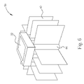
- FIG. 8 is a schematic diagram showing heat transferring paths and a structure for a heat transferring pipe and a heat transferring plate.
- FIG. 3 is a schematic cross-sectional diagram showing an LED module according to an embodiment of the present invention.
- the light module 30 according to the present invention comprises a light unit 32 , a heat transferring plate 38 , and a plurality of heat dissipating fins 40 .
- the light unit 32 provides a light source and typically comprises a substrate 34 and a light-emitting element 36 .
- the substrate 34 is preferably in a flat shape for correspondingly matching up the shape of the heat transferring plate 38 .
- the light-emitting element 36 may be a traditional electric bulb light source, or a packaged LED element, module, or light engine, such as the conventional LED as mentioned above, not limited to lead type or chip type LEDs.
- the light-emitting element 36 also may be a package body comprising one LED or an aggregate of a plurality of LEDs.
- the light-emitting element 36 also may be an aggregate comprising a plurality of LEDs package bodies.
- a commercial LED product can be used in the present invention. Since a high brightness is desired, the light-emitting element 36 probably produces an amount of heat.
- the substrate 34 preferably comprises a good heat conducting material for heat transfer. The conduction direction for heat may be as shown by the heat flow 42 in FIG. 3 .
- the heat transferring plate 38 is positioned on the bottom surface of the light unit 32 by means of, for example, adhesion to the substrate 34 with a conductive silver adhesive or a solder, such that the heat transferring plate 38 is in contact with the substrate 34 to transfer heat generated by the light unit 32 .
- the heat transferring plate 38 is a hollow structure with a double-layered wall, as shown in FIG. 8 .
- the outer wall 52 comprises a heat conducting material, such as metal.
- the inner wall 54 comprises a porous heat conducting material, which may be formed by, for example, depositing cupper powder on the internal surface of the outer wall 52 .
- the porous heat conducting material can adsorb liquid. Since both the outer wall and the inner wall each comprise a heat conducting material, they can transfer heat.
- the heat transferring plate 38 further comprises a liquid 56 adsorbed by the porous inner wall 54 .
- the liquid 56 comprises a heat medium material. After the heat medium material absorbs heat from the porous inner wall 54 , it may evaporate to become a gas and diffuse in a space 58 inside the heat transferring plate 38 , thereby to transfer the heat to a relative cold place. The gas may condense at the relative cold place on the inner wall to recover the state of liquid, and the liquid will evaporate and become the gas again when receiving a heat.
- the heat transferring plate 38 and the light unit 32 are accommodated among a plurality of heat dissipating fins 40 .
- the heat dissipating fin comprises a heat conducting sheet material, such as a metal sheet, typically an aluminum sheet or a copper sheet, having a large area for advantageously dissipating heat.
- the heat dissipating fins 40 are arranged upright and perpendicularly to the bottom surface direction of the light unit 32 and have a recess with a size and a shape corresponding to the heat transferring plate 38 and the light unit 32 for accommodating them and adhering to each other.
- the heat dissipating fins 40 may be arranged to intersect and exhibit a grid shape by a top view.
- the recess is designed to accommodate the light unit 32 and the heat transferring plate 38 .
- the shape of the recess is not particularly limited as long as it can match up the product design and use. Such that, the heat from the heat transferring plate 38 can be dissipated into an ambience, such as the air, by the heat dissipating fins 40 .
- the interfaces between two of the light unit 32 , the heat transferring plate 38 , and the heat dissipating fins 40 are each filled with a heat dissipating paste or gel, for increasing the contact area for heat conduction, such that the heat dissipation is more efficient.
- the light module 50 in another embodiment according to the present invention comprises a light unit 32 , a plurality of heat transferring pipes, and a plurality of heat dissipating fins 40 .
- the light unit 32 provides a light source, as mentioned in the above.
- the heat transferring pipes 44 are positioned on the bottom surface of the substrate 34 of the light unit 32 , such that the heat transferring plate 38 is in contact with the substrate 34 to transfer heat generated by the light-emitting element 36 .
- the heat transferring pipes 44 are each a closed hollow column structure with a double-layered wall, as shown in FIG. 8 .
- the outer wall and the inner wall have a structure similar to the above-mentioned heat transferring plate 38 .
- the heat transferring pipe comprises a liquid 56 as a heat medium.
- the heat medium After the heat medium absorbs heat from the porous inner wall 54 , it may evaporate to become a gas and diffuse in a space 58 inside the heat transferring pipe 44 , thereby to transfer the heat to a relative cold place.
- the gas may condense at the relative cold place (such as the place far from the light unit) on the inner wall to recover the state of liquid, and the liquid will evaporate and become the gas again when receiving a heat.
- the heat dissipating fins each contact with the heat transferring pipes to transfer heat from the heat transferring pipes into ambience.
- the heat dissipating fins 40 may only connect to the peripheral ones of the heat transferring pipes 44 with a silver adhesive or a solder and extend outward. Gaps 46 formed among the heat transferring pipes may be further filled with a heat dissipating paste or gel for heat dissipation.
- the heat dissipating fins 40 may intersect to form a plurality of holes having polygonal patterns in plan view among the intersected heat dissipating fins.
- the heat transferring pipes 44 are disposed through the holes and contact with the heat dissipating fins 40 for heat transfer and dissipation. Gaps formed between the heat dissipating fins 40 and the heat transferring pipes 44 may be filled with a heat dissipating paste or gel.
- the heat transferring plate or pipes, the heat dissipating fins, and the light unit are combined to construct a light module. Since there is a liquid as a heat medium inside the heat transferring plate or pipes, after heat transferred to the porous inner wall, the liquid adsorbed on the inner wall will absorb the heat and evaporate as a gas and promptly diffuse in the space inside the plate or pipes. Then, the gas condenses at places having relatively low temperatures on the inner wall, and the heat is simultaneously dissipated from the inner wall to the outer wall, then into the ambience. Therefore, a fast heat dissipation effect is achieved.
- the heat transferring plate or pipes are selected to match up the desired design for the entire light module.
- the heat transferring plate is suitably used in a flat light source device.
- the heat transferring pipes are suitably used in a light module having an elongated size and a high intensity light source.
- the light module according to the present invention may have a structure of small sized but relatively high heat dissipation design, and, accordingly, high power light modules or engines with LEDs can be attained and have advantages of fast and uniform heat dissipation without hot spots.
- the LED light modules have improved reliability and lifetime.
- the light module according to the present invention is adaptable to various applications.
- Various designs for the heat transferring plate or the heat transferring pipes can be selected for various light module products in various applications, such as, general illuminations, LCD back light modules, vehicle illuminations, and decoration illuminations, etc.
Abstract
Description
Claims (7)
Priority Applications (1)
| Application Number | Priority Date | Filing Date | Title |
|---|---|---|---|
| US10/908,339 US7270446B2 (en) | 2005-05-09 | 2005-05-09 | Light module with combined heat transferring plate and heat transferring pipes |
Applications Claiming Priority (1)
| Application Number | Priority Date | Filing Date | Title |
|---|---|---|---|
| US10/908,339 US7270446B2 (en) | 2005-05-09 | 2005-05-09 | Light module with combined heat transferring plate and heat transferring pipes |
Publications (2)
| Publication Number | Publication Date |
|---|---|
| US20060250800A1 US20060250800A1 (en) | 2006-11-09 |
| US7270446B2 true US7270446B2 (en) | 2007-09-18 |
Family
ID=37393853
Family Applications (1)
| Application Number | Title | Priority Date | Filing Date |
|---|---|---|---|
| US10/908,339 Active 2025-07-24 US7270446B2 (en) | 2005-05-09 | 2005-05-09 | Light module with combined heat transferring plate and heat transferring pipes |
Country Status (1)
| Country | Link |
|---|---|
| US (1) | US7270446B2 (en) |
Cited By (38)
| Publication number | Priority date | Publication date | Assignee | Title |
|---|---|---|---|---|
| US20070086196A1 (en) * | 2005-10-18 | 2007-04-19 | National Tsing Hua University | Heat dissipation devices for and LED lamp set |
| US20070189012A1 (en) * | 2003-09-26 | 2007-08-16 | Advanced Thermal Device Inc. | Light emitting diode illumination apparatus and heat dissipating method therefor |
| US20070279909A1 (en) * | 2006-06-06 | 2007-12-06 | Jia-Hao Li | Heat-Dissipating Structure Having Multiple Heat Pipes For LED Lamp |
| US20070285926A1 (en) * | 2006-06-08 | 2007-12-13 | Lighting Science Group Corporation | Method and apparatus for cooling a lightbulb |
| US20080007955A1 (en) * | 2006-07-05 | 2008-01-10 | Jia-Hao Li | Multiple-Set Heat-Dissipating Structure For LED Lamp |
| US20080007954A1 (en) * | 2006-07-05 | 2008-01-10 | Jia-Hao Li | Heat-Dissipating Structure For LED Lamp |
| US20080062694A1 (en) * | 2006-09-07 | 2008-03-13 | Foxconn Technology Co., Ltd. | Heat dissipation device for light emitting diode module |
| US20090034250A1 (en) * | 2005-08-19 | 2009-02-05 | Neobulb Technologies, Inc. | System in package high power high efficiency light-emitting diode lamp |
| US20090200939A1 (en) * | 2006-05-02 | 2009-08-13 | Superbulbs, Inc. | Method of Light Dispersion and Preferential Scattering of Certain Wavelengths of Light-Emitting Diodes and Bulbs Constructed Therefrom |
| US20090257220A1 (en) * | 2006-05-02 | 2009-10-15 | Superbulbs, Inc. | Plastic led bulb |
| US20090309473A1 (en) * | 2006-05-02 | 2009-12-17 | Superbulbs, Inc. | Heat removal design for led bulbs |
| US20100008070A1 (en) * | 2008-07-10 | 2010-01-14 | Wai Hon Lee | Back light module with diffractive couplers |
| US20100027260A1 (en) * | 2008-07-30 | 2010-02-04 | Lustrous International Technology Ltd. | Light emitting diode lamp |
| US20110194258A1 (en) * | 2010-02-05 | 2011-08-11 | Kodadek Iii Robert E | Thermal Management System For Electrical Components And Method Of Producing Same |
| US20110215701A1 (en) * | 2010-03-03 | 2011-09-08 | Cree, Inc. | Led lamp incorporating remote phosphor with heat dissipation features |
| US20110215698A1 (en) * | 2010-03-03 | 2011-09-08 | Cree, Inc. | Led lamp with active cooling element |
| US20110215697A1 (en) * | 2010-03-03 | 2011-09-08 | Cree, Inc. | Led lamp with active cooling element |
| US8415695B2 (en) | 2007-10-24 | 2013-04-09 | Switch Bulb Company, Inc. | Diffuser for LED light sources |
| US8439528B2 (en) | 2007-10-03 | 2013-05-14 | Switch Bulb Company, Inc. | Glass LED light bulbs |
| US8591069B2 (en) | 2011-09-21 | 2013-11-26 | Switch Bulb Company, Inc. | LED light bulb with controlled color distribution using quantum dots |
| US8736171B2 (en) | 2010-09-03 | 2014-05-27 | Zybron Optical Electronics, Inc. | Light emitting diode replacement bulbs |
| US8882284B2 (en) | 2010-03-03 | 2014-11-11 | Cree, Inc. | LED lamp or bulb with remote phosphor and diffuser configuration with enhanced scattering properties |
| US20150097692A1 (en) * | 2013-10-08 | 2015-04-09 | Vincenzo Di Giovine | Light indicator |
| US9024517B2 (en) | 2010-03-03 | 2015-05-05 | Cree, Inc. | LED lamp with remote phosphor and diffuser configuration utilizing red emitters |
| US9057511B2 (en) | 2010-03-03 | 2015-06-16 | Cree, Inc. | High efficiency solid state lamp and bulb |
| US9062830B2 (en) | 2010-03-03 | 2015-06-23 | Cree, Inc. | High efficiency solid state lamp and bulb |
| US9068701B2 (en) | 2012-01-26 | 2015-06-30 | Cree, Inc. | Lamp structure with remote LED light source |
| US9217544B2 (en) | 2010-03-03 | 2015-12-22 | Cree, Inc. | LED based pedestal-type lighting structure |
| US9234655B2 (en) | 2011-02-07 | 2016-01-12 | Cree, Inc. | Lamp with remote LED light source and heat dissipating elements |
| US9275979B2 (en) | 2010-03-03 | 2016-03-01 | Cree, Inc. | Enhanced color rendering index emitter through phosphor separation |
| US9310030B2 (en) | 2010-03-03 | 2016-04-12 | Cree, Inc. | Non-uniform diffuser to scatter light into uniform emission pattern |
| US9316361B2 (en) | 2010-03-03 | 2016-04-19 | Cree, Inc. | LED lamp with remote phosphor and diffuser configuration |
| US9412926B2 (en) | 2005-06-10 | 2016-08-09 | Cree, Inc. | High power solid-state lamp |
| US9488359B2 (en) * | 2012-03-26 | 2016-11-08 | Cree, Inc. | Passive phase change radiators for LED lamps and fixtures |
| US10359151B2 (en) | 2010-03-03 | 2019-07-23 | Ideal Industries Lighting Llc | Solid state lamp with thermal spreading elements and light directing optics |
| US10451251B2 (en) | 2010-08-02 | 2019-10-22 | Ideal Industries Lighting, LLC | Solid state lamp with light directing optics and diffuser |
| US10571113B2 (en) | 2015-07-24 | 2020-02-25 | Fluence Bioengineering, Inc. | Systems and methods for a heat sink |
| US11251164B2 (en) | 2011-02-16 | 2022-02-15 | Creeled, Inc. | Multi-layer conversion material for down conversion in solid state lighting |
Families Citing this family (14)
| Publication number | Priority date | Publication date | Assignee | Title |
|---|---|---|---|---|
| US7922359B2 (en) * | 2006-07-17 | 2011-04-12 | Liquidleds Lighting Corp. | Liquid-filled LED lamp with heat dissipation means |
| CN101222006A (en) * | 2007-01-12 | 2008-07-16 | 泰硕电子股份有限公司 | Light emitting diode with heat radiating device (2) |
| CN101222007A (en) * | 2007-01-12 | 2008-07-16 | 泰硕电子股份有限公司 | Light emitting diode with heat radiating device (3) |
| FR2913483B1 (en) * | 2007-03-08 | 2013-02-01 | Lyracom | LED LIGHTING DEVICE |
| TWI333533B (en) * | 2007-07-06 | 2010-11-21 | Harvatek Corp | Led lamp structure and system with high-efficiency heat-dissipating function |
| DE102007046520A1 (en) * | 2007-09-28 | 2009-04-02 | Osram Opto Semiconductors Gmbh | Light-emitting surface element and method for producing a light-emitting surface element |
| US8556448B2 (en) * | 2007-12-19 | 2013-10-15 | Osram Gesellschaft Mit Beschraenkter Haftung | Airfield lighting device |
| EP2105659A1 (en) * | 2008-03-27 | 2009-09-30 | Wen-Long Chyn | LED lamp having higher efficiency |
| CN101319774A (en) * | 2008-06-24 | 2008-12-10 | 杨洪武 | Passive radiator and heat radiating device of road lamp |
| US9383089B2 (en) | 2008-06-24 | 2016-07-05 | Hongwu Yang | Heat radiation device for a lighting device |
| TWM378614U (en) * | 2009-06-29 | 2010-04-11 | Te-Lung Chen | The ceramic radiator with conductive circuit |
| CN102606905A (en) * | 2011-10-21 | 2012-07-25 | 杭州临安新联电器工业有限公司 | Heat-pipe type LED (light emitting diode) lamp |
| FR3004787B1 (en) * | 2013-04-19 | 2017-09-08 | Valeo Vision | COOLING DEVICE AND LIGHTING OR SIGNALING DEVICE FOR A MOTOR VEHICLE COMPRISING SUCH AN ORGAN |
| CN104501114B (en) * | 2014-12-19 | 2022-12-23 | 漳州立达信光电子科技有限公司 | Heat dissipation structure of LED lamp |
Citations (14)
| Publication number | Priority date | Publication date | Assignee | Title |
|---|---|---|---|---|
| US4204246A (en) * | 1976-02-14 | 1980-05-20 | Sony Corporation | Cooling assembly for cooling electrical parts wherein a heat pipe is attached to a heat conducting portion of a heat conductive block |
| US6517221B1 (en) * | 1999-06-18 | 2003-02-11 | Ciena Corporation | Heat pipe heat sink for cooling a laser diode |
| US6517218B2 (en) * | 2000-03-31 | 2003-02-11 | Relume Corporation | LED integrated heat sink |
| TW595016B (en) | 2003-02-27 | 2004-06-21 | Kaylu Ind Corp | LED module with high heat-dissipation efficiency |
| US20040141291A1 (en) * | 2003-01-21 | 2004-07-22 | Chen Chao Ming | High-efficiency heat sink and method for manufacturing the same |
| US20040233671A1 (en) * | 2001-09-13 | 2004-11-25 | Gerhard Staufert | Led-luminous panel and carrier plate |
| US20040264195A1 (en) * | 2003-06-25 | 2004-12-30 | Chia-Fu Chang | Led light source having a heat sink |
| US20050047170A1 (en) * | 2003-09-02 | 2005-03-03 | Guide Corporation (A Delaware Corporation) | LED heat sink for use with standard socket hole |
| US20050047140A1 (en) * | 2003-08-25 | 2005-03-03 | Jung-Chien Chang | Lighting device composed of a thin light emitting diode module |
| US20050063159A1 (en) * | 2003-09-23 | 2005-03-24 | Richard Ma | Heat-dissipating fin module |
| US6910794B2 (en) * | 2003-04-25 | 2005-06-28 | Guide Corporation | Automotive lighting assembly cooling system |
| US20050231983A1 (en) * | 2002-08-23 | 2005-10-20 | Dahm Jonathan S | Method and apparatus for using light emitting diodes |
| US20060001384A1 (en) * | 2004-06-30 | 2006-01-05 | Industrial Technology Research Institute | LED lamp |
| US20060092639A1 (en) * | 2004-10-29 | 2006-05-04 | Goldeneye, Inc. | High brightness light emitting diode light source |
-
2005
- 2005-05-09 US US10/908,339 patent/US7270446B2/en active Active
Patent Citations (14)
| Publication number | Priority date | Publication date | Assignee | Title |
|---|---|---|---|---|
| US4204246A (en) * | 1976-02-14 | 1980-05-20 | Sony Corporation | Cooling assembly for cooling electrical parts wherein a heat pipe is attached to a heat conducting portion of a heat conductive block |
| US6517221B1 (en) * | 1999-06-18 | 2003-02-11 | Ciena Corporation | Heat pipe heat sink for cooling a laser diode |
| US6517218B2 (en) * | 2000-03-31 | 2003-02-11 | Relume Corporation | LED integrated heat sink |
| US20040233671A1 (en) * | 2001-09-13 | 2004-11-25 | Gerhard Staufert | Led-luminous panel and carrier plate |
| US20050231983A1 (en) * | 2002-08-23 | 2005-10-20 | Dahm Jonathan S | Method and apparatus for using light emitting diodes |
| US20040141291A1 (en) * | 2003-01-21 | 2004-07-22 | Chen Chao Ming | High-efficiency heat sink and method for manufacturing the same |
| TW595016B (en) | 2003-02-27 | 2004-06-21 | Kaylu Ind Corp | LED module with high heat-dissipation efficiency |
| US6910794B2 (en) * | 2003-04-25 | 2005-06-28 | Guide Corporation | Automotive lighting assembly cooling system |
| US20040264195A1 (en) * | 2003-06-25 | 2004-12-30 | Chia-Fu Chang | Led light source having a heat sink |
| US20050047140A1 (en) * | 2003-08-25 | 2005-03-03 | Jung-Chien Chang | Lighting device composed of a thin light emitting diode module |
| US20050047170A1 (en) * | 2003-09-02 | 2005-03-03 | Guide Corporation (A Delaware Corporation) | LED heat sink for use with standard socket hole |
| US20050063159A1 (en) * | 2003-09-23 | 2005-03-24 | Richard Ma | Heat-dissipating fin module |
| US20060001384A1 (en) * | 2004-06-30 | 2006-01-05 | Industrial Technology Research Institute | LED lamp |
| US20060092639A1 (en) * | 2004-10-29 | 2006-05-04 | Goldeneye, Inc. | High brightness light emitting diode light source |
Cited By (58)
| Publication number | Priority date | Publication date | Assignee | Title |
|---|---|---|---|---|
| US20070189012A1 (en) * | 2003-09-26 | 2007-08-16 | Advanced Thermal Device Inc. | Light emitting diode illumination apparatus and heat dissipating method therefor |
| US9412926B2 (en) | 2005-06-10 | 2016-08-09 | Cree, Inc. | High power solid-state lamp |
| US20090034250A1 (en) * | 2005-08-19 | 2009-02-05 | Neobulb Technologies, Inc. | System in package high power high efficiency light-emitting diode lamp |
| US7905644B2 (en) * | 2005-08-19 | 2011-03-15 | Neobulb Technologies, Inc. | System in package high power high efficiency light-emitting diode lamp |
| US20070086196A1 (en) * | 2005-10-18 | 2007-04-19 | National Tsing Hua University | Heat dissipation devices for and LED lamp set |
| US7637633B2 (en) * | 2005-10-18 | 2009-12-29 | National Tsing Hua University | Heat dissipation devices for an LED lamp set |
| US8702257B2 (en) | 2006-05-02 | 2014-04-22 | Switch Bulb Company, Inc. | Plastic LED bulb |
| US8853921B2 (en) | 2006-05-02 | 2014-10-07 | Switch Bulb Company, Inc. | Heat removal design for LED bulbs |
| US8569949B2 (en) | 2006-05-02 | 2013-10-29 | Switch Bulb Company, Inc. | Method of light dispersion and preferential scattering of certain wavelengths of light-emitting diodes and bulbs constructed therefrom |
| US8547002B2 (en) | 2006-05-02 | 2013-10-01 | Switch Bulb Company, Inc. | Heat removal design for LED bulbs |
| US8704442B2 (en) | 2006-05-02 | 2014-04-22 | Switch Bulb Company, Inc. | Method of light dispersion and preferential scattering of certain wavelengths of light for light-emitting diodes and bulbs constructed therefrom |
| US20090200939A1 (en) * | 2006-05-02 | 2009-08-13 | Superbulbs, Inc. | Method of Light Dispersion and Preferential Scattering of Certain Wavelengths of Light-Emitting Diodes and Bulbs Constructed Therefrom |
| US20090257220A1 (en) * | 2006-05-02 | 2009-10-15 | Superbulbs, Inc. | Plastic led bulb |
| US20090309473A1 (en) * | 2006-05-02 | 2009-12-17 | Superbulbs, Inc. | Heat removal design for led bulbs |
| US8193702B2 (en) | 2006-05-02 | 2012-06-05 | Switch Bulb Company, Inc. | Method of light dispersion and preferential scattering of certain wavelengths of light-emitting diodes and bulbs constructed therefrom |
| US7467878B2 (en) * | 2006-06-06 | 2008-12-23 | Jaffe Limited | Heat-dissipating structure having multiple heat pipes for LED lamp |
| US20070279909A1 (en) * | 2006-06-06 | 2007-12-06 | Jia-Hao Li | Heat-Dissipating Structure Having Multiple Heat Pipes For LED Lamp |
| US20070285926A1 (en) * | 2006-06-08 | 2007-12-13 | Lighting Science Group Corporation | Method and apparatus for cooling a lightbulb |
| US7824075B2 (en) * | 2006-06-08 | 2010-11-02 | Lighting Science Group Corporation | Method and apparatus for cooling a lightbulb |
| US20080007955A1 (en) * | 2006-07-05 | 2008-01-10 | Jia-Hao Li | Multiple-Set Heat-Dissipating Structure For LED Lamp |
| US7494248B2 (en) * | 2006-07-05 | 2009-02-24 | Jaffe Limited | Heat-dissipating structure for LED lamp |
| US7494249B2 (en) * | 2006-07-05 | 2009-02-24 | Jaffe Limited | Multiple-set heat-dissipating structure for LED lamp |
| US20080007954A1 (en) * | 2006-07-05 | 2008-01-10 | Jia-Hao Li | Heat-Dissipating Structure For LED Lamp |
| US20080062694A1 (en) * | 2006-09-07 | 2008-03-13 | Foxconn Technology Co., Ltd. | Heat dissipation device for light emitting diode module |
| US8752984B2 (en) | 2007-10-03 | 2014-06-17 | Switch Bulb Company, Inc. | Glass LED light bulbs |
| US8439528B2 (en) | 2007-10-03 | 2013-05-14 | Switch Bulb Company, Inc. | Glass LED light bulbs |
| US8981405B2 (en) | 2007-10-24 | 2015-03-17 | Switch Bulb Company, Inc. | Diffuser for LED light sources |
| US8415695B2 (en) | 2007-10-24 | 2013-04-09 | Switch Bulb Company, Inc. | Diffuser for LED light sources |
| US20100008070A1 (en) * | 2008-07-10 | 2010-01-14 | Wai Hon Lee | Back light module with diffractive couplers |
| US20100027260A1 (en) * | 2008-07-30 | 2010-02-04 | Lustrous International Technology Ltd. | Light emitting diode lamp |
| US20110194258A1 (en) * | 2010-02-05 | 2011-08-11 | Kodadek Iii Robert E | Thermal Management System For Electrical Components And Method Of Producing Same |
| US8767398B2 (en) | 2010-02-05 | 2014-07-01 | Black Tank Llc | Thermal management system for electrical components and method of producing same |
| US9217544B2 (en) | 2010-03-03 | 2015-12-22 | Cree, Inc. | LED based pedestal-type lighting structure |
| US20110215697A1 (en) * | 2010-03-03 | 2011-09-08 | Cree, Inc. | Led lamp with active cooling element |
| US9275979B2 (en) | 2010-03-03 | 2016-03-01 | Cree, Inc. | Enhanced color rendering index emitter through phosphor separation |
| US9310030B2 (en) | 2010-03-03 | 2016-04-12 | Cree, Inc. | Non-uniform diffuser to scatter light into uniform emission pattern |
| US8931933B2 (en) | 2010-03-03 | 2015-01-13 | Cree, Inc. | LED lamp with active cooling element |
| US20110215698A1 (en) * | 2010-03-03 | 2011-09-08 | Cree, Inc. | Led lamp with active cooling element |
| US10359151B2 (en) | 2010-03-03 | 2019-07-23 | Ideal Industries Lighting Llc | Solid state lamp with thermal spreading elements and light directing optics |
| US9024517B2 (en) | 2010-03-03 | 2015-05-05 | Cree, Inc. | LED lamp with remote phosphor and diffuser configuration utilizing red emitters |
| US9057511B2 (en) | 2010-03-03 | 2015-06-16 | Cree, Inc. | High efficiency solid state lamp and bulb |
| US9062830B2 (en) | 2010-03-03 | 2015-06-23 | Cree, Inc. | High efficiency solid state lamp and bulb |
| US9625105B2 (en) | 2010-03-03 | 2017-04-18 | Cree, Inc. | LED lamp with active cooling element |
| US9500325B2 (en) | 2010-03-03 | 2016-11-22 | Cree, Inc. | LED lamp incorporating remote phosphor with heat dissipation features |
| US20110215701A1 (en) * | 2010-03-03 | 2011-09-08 | Cree, Inc. | Led lamp incorporating remote phosphor with heat dissipation features |
| US9316361B2 (en) | 2010-03-03 | 2016-04-19 | Cree, Inc. | LED lamp with remote phosphor and diffuser configuration |
| US8882284B2 (en) | 2010-03-03 | 2014-11-11 | Cree, Inc. | LED lamp or bulb with remote phosphor and diffuser configuration with enhanced scattering properties |
| US10451251B2 (en) | 2010-08-02 | 2019-10-22 | Ideal Industries Lighting, LLC | Solid state lamp with light directing optics and diffuser |
| US8736171B2 (en) | 2010-09-03 | 2014-05-27 | Zybron Optical Electronics, Inc. | Light emitting diode replacement bulbs |
| US9234655B2 (en) | 2011-02-07 | 2016-01-12 | Cree, Inc. | Lamp with remote LED light source and heat dissipating elements |
| US11251164B2 (en) | 2011-02-16 | 2022-02-15 | Creeled, Inc. | Multi-layer conversion material for down conversion in solid state lighting |
| US8591069B2 (en) | 2011-09-21 | 2013-11-26 | Switch Bulb Company, Inc. | LED light bulb with controlled color distribution using quantum dots |
| US9068701B2 (en) | 2012-01-26 | 2015-06-30 | Cree, Inc. | Lamp structure with remote LED light source |
| US9488359B2 (en) * | 2012-03-26 | 2016-11-08 | Cree, Inc. | Passive phase change radiators for LED lamps and fixtures |
| US9483919B2 (en) * | 2013-10-08 | 2016-11-01 | Combustion And Energy S.R.L. | Light indicator |
| US20150097692A1 (en) * | 2013-10-08 | 2015-04-09 | Vincenzo Di Giovine | Light indicator |
| US11346540B2 (en) | 2015-07-24 | 2022-05-31 | Fluence Bioengineering, Inc. | Systems and methods for a heat sink |
| US10571113B2 (en) | 2015-07-24 | 2020-02-25 | Fluence Bioengineering, Inc. | Systems and methods for a heat sink |
Also Published As
| Publication number | Publication date |
|---|---|
| US20060250800A1 (en) | 2006-11-09 |
Similar Documents
| Publication | Publication Date | Title |
|---|---|---|
| US7270446B2 (en) | Light module with combined heat transferring plate and heat transferring pipes | |
| US20040004435A1 (en) | Immersion cooling type light emitting diode and its packaging method | |
| CN101162816B (en) | Electric connector | |
| CN102484195B (en) | Luminescent device and use the light unit of this luminescent device | |
| US7115911B2 (en) | LED module and method of packaging the same | |
| US20090302345A1 (en) | Led lamp module and fabrication method thereof | |
| JP2008293966A (en) | Light-emitting diode lamp | |
| JP2008294428A (en) | Light-emitting diode package | |
| US20110156061A1 (en) | Light emission module with high-efficiency light emission and high-efficiency heat dissipation and applications thereof | |
| KR101134671B1 (en) | LED lamp module with the cooling structure | |
| US20080017876A1 (en) | Si-substrate and structure of opto-electronic package having the same | |
| KR20140118466A (en) | Light emitting device and lighting device including the same | |
| JP2007096320A (en) | Light-emitting device | |
| US7939919B2 (en) | LED-packaging arrangement and light bar employing the same | |
| CN102709281A (en) | Double fluorescent thin film two-sided light-emitting planar wafer LED (Light-Emitting Diode) array light source | |
| CN101222007A (en) | Light emitting diode with heat radiating device (3) | |
| US20100044727A1 (en) | Led package structure | |
| CN101126863A (en) | Light-emitting diode light source module with heat dissipation structure | |
| CN101207169B (en) | Luminous chip encapsulation body and light source component | |
| CN102723324A (en) | Double-face light emitting planar wafer type LED (Light-Emitting Diode) packaging structure | |
| US20080304270A1 (en) | Light emitting diode heat dissipation module | |
| CN202708919U (en) | Tower-shaped light-emitting diode (LED) automobile lamp | |
| KR101022485B1 (en) | Heat radiation structure of led illuminating device using heat pipe module | |
| CN101222006A (en) | Light emitting diode with heat radiating device (2) | |
| CN101123227A (en) | Luminescent and heat radiation device and its encapsulation making method |
Legal Events
| Date | Code | Title | Description |
|---|---|---|---|
| AS | Assignment |
Owner name: LIGHTHOUSE TECHNOLOGY CO., LTD, TAIWAN Free format text: ASSIGNMENT OF ASSIGNORS INTEREST;ASSIGNORS:CHANG, CHIH-CHIN;HUANG, TENG-HUEI;LEE, CHIEN-LUNG;REEL/FRAME:015982/0299 Effective date: 20050505 |
|
| AS | Assignment |
Owner name: LIGHTHOUSE TECHNOLOGY CO., LTD, TAIWAN Free format text: CHANGE OF THE ADDRESS OF THE ASSIGNEE;ASSIGNOR:LIGHTHOUSE TECHNOLOGY CO., LTD;REEL/FRAME:019160/0483 Effective date: 20070411 |
|
| STCF | Information on status: patent grant |
Free format text: PATENTED CASE |
|
| AS | Assignment |
Owner name: LEXTAR ELECTRONICS CORP.,TAIWAN Free format text: MERGER;ASSIGNOR:LIGHTHOUSE TECHNOLOGY CO., LTD.;REEL/FRAME:024278/0767 Effective date: 20100315 |
|
| FEPP | Fee payment procedure |
Free format text: PAT HOLDER NO LONGER CLAIMS SMALL ENTITY STATUS, ENTITY STATUS SET TO UNDISCOUNTED (ORIGINAL EVENT CODE: STOL); ENTITY STATUS OF PATENT OWNER: LARGE ENTITY |
|
| FPAY | Fee payment |
Year of fee payment: 4 |
|
| FPAY | Fee payment |
Year of fee payment: 8 |
|
| MAFP | Maintenance fee payment |
Free format text: PAYMENT OF MAINTENANCE FEE, 12TH YEAR, LARGE ENTITY (ORIGINAL EVENT CODE: M1553); ENTITY STATUS OF PATENT OWNER: LARGE ENTITY Year of fee payment: 12 |