US7255115B2 - Apparatus for cleaning semiconductor wafers - Google Patents
Apparatus for cleaning semiconductor wafers Download PDFInfo
- Publication number
- US7255115B2 US7255115B2 US10/410,278 US41027803A US7255115B2 US 7255115 B2 US7255115 B2 US 7255115B2 US 41027803 A US41027803 A US 41027803A US 7255115 B2 US7255115 B2 US 7255115B2
- Authority
- US
- United States
- Prior art keywords
- housing
- chamber
- spray pipe
- alcohol
- vapor
- Prior art date
- Legal status (The legal status is an assumption and is not a legal conclusion. Google has not performed a legal analysis and makes no representation as to the accuracy of the status listed.)
- Expired - Fee Related, expires
Links
Images


Classifications
-
- H—ELECTRICITY
- H01—ELECTRIC ELEMENTS
- H01L—SEMICONDUCTOR DEVICES NOT COVERED BY CLASS H10
- H01L21/00—Processes or apparatus adapted for the manufacture or treatment of semiconductor or solid state devices or of parts thereof
- H01L21/02—Manufacture or treatment of semiconductor devices or of parts thereof
- H01L21/04—Manufacture or treatment of semiconductor devices or of parts thereof the devices having at least one potential-jump barrier or surface barrier, e.g. PN junction, depletion layer or carrier concentration layer
- H01L21/18—Manufacture or treatment of semiconductor devices or of parts thereof the devices having at least one potential-jump barrier or surface barrier, e.g. PN junction, depletion layer or carrier concentration layer the devices having semiconductor bodies comprising elements of Group IV of the Periodic System or AIIIBV compounds with or without impurities, e.g. doping materials
- H01L21/30—Treatment of semiconductor bodies using processes or apparatus not provided for in groups H01L21/20 - H01L21/26
- H01L21/302—Treatment of semiconductor bodies using processes or apparatus not provided for in groups H01L21/20 - H01L21/26 to change their surface-physical characteristics or shape, e.g. etching, polishing, cutting
- H01L21/304—Mechanical treatment, e.g. grinding, polishing, cutting
-
- H—ELECTRICITY
- H01—ELECTRIC ELEMENTS
- H01L—SEMICONDUCTOR DEVICES NOT COVERED BY CLASS H10
- H01L21/00—Processes or apparatus adapted for the manufacture or treatment of semiconductor or solid state devices or of parts thereof
- H01L21/67—Apparatus specially adapted for handling semiconductor or electric solid state devices during manufacture or treatment thereof; Apparatus specially adapted for handling wafers during manufacture or treatment of semiconductor or electric solid state devices or components ; Apparatus not specifically provided for elsewhere
- H01L21/67005—Apparatus not specifically provided for elsewhere
- H01L21/67011—Apparatus for manufacture or treatment
- H01L21/67017—Apparatus for fluid treatment
- H01L21/67028—Apparatus for fluid treatment for cleaning followed by drying, rinsing, stripping, blasting or the like
- H01L21/6704—Apparatus for fluid treatment for cleaning followed by drying, rinsing, stripping, blasting or the like for wet cleaning or washing
- H01L21/67057—Apparatus for fluid treatment for cleaning followed by drying, rinsing, stripping, blasting or the like for wet cleaning or washing with the semiconductor substrates being dipped in baths or vessels
-
- B—PERFORMING OPERATIONS; TRANSPORTING
- B08—CLEANING
- B08B—CLEANING IN GENERAL; PREVENTION OF FOULING IN GENERAL
- B08B3/00—Cleaning by methods involving the use or presence of liquid or steam
- B08B3/04—Cleaning involving contact with liquid
- B08B3/10—Cleaning involving contact with liquid with additional treatment of the liquid or of the object being cleaned, e.g. by heat, by electricity or by vibration
- B08B3/102—Cleaning involving contact with liquid with additional treatment of the liquid or of the object being cleaned, e.g. by heat, by electricity or by vibration with means for agitating the liquid
-
- H—ELECTRICITY
- H01—ELECTRIC ELEMENTS
- H01L—SEMICONDUCTOR DEVICES NOT COVERED BY CLASS H10
- H01L21/00—Processes or apparatus adapted for the manufacture or treatment of semiconductor or solid state devices or of parts thereof
- H01L21/67—Apparatus specially adapted for handling semiconductor or electric solid state devices during manufacture or treatment thereof; Apparatus specially adapted for handling wafers during manufacture or treatment of semiconductor or electric solid state devices or components ; Apparatus not specifically provided for elsewhere
- H01L21/67005—Apparatus not specifically provided for elsewhere
- H01L21/67011—Apparatus for manufacture or treatment
- H01L21/67017—Apparatus for fluid treatment
- H01L21/67028—Apparatus for fluid treatment for cleaning followed by drying, rinsing, stripping, blasting or the like
-
- Y—GENERAL TAGGING OF NEW TECHNOLOGICAL DEVELOPMENTS; GENERAL TAGGING OF CROSS-SECTIONAL TECHNOLOGIES SPANNING OVER SEVERAL SECTIONS OF THE IPC; TECHNICAL SUBJECTS COVERED BY FORMER USPC CROSS-REFERENCE ART COLLECTIONS [XRACs] AND DIGESTS
- Y10—TECHNICAL SUBJECTS COVERED BY FORMER USPC
- Y10S—TECHNICAL SUBJECTS COVERED BY FORMER USPC CROSS-REFERENCE ART COLLECTIONS [XRACs] AND DIGESTS
- Y10S134/00—Cleaning and liquid contact with solids
- Y10S134/902—Semiconductor wafer
Definitions
- the present invention relates to an apparatus for manufacturing semiconductor devices. More particularly, the present invention relates to an apparatus for cleaning semiconductor wafers in accordance with the Marangoni principle.
- IC integrated circuit
- the wafer is subjected to a series of semiconductor device manufacturing processes such as photolithography, chemical or physical vapor deposition and plasma etching processes.
- Foreign materials such as residual chemicals, small particles, and other contaminants, may remain on the surface of the wafer after these processes are carried out. The foreign materials must be removed from the surface of the wafer to assure the quality of the IC devices.
- a wafer cleaning process may include both rinsing and drying the wafer to remove foreign materials.
- a silicon wafer is generally rinsed using de-ionized water.
- the de-ionized water is an aggressive solvent against silicon and will thus eventually dissolve the silicon wafer. Accordingly, the wafer must be completely dried after being rinsed with the de-ionized water.
- An object of the present invention is to provide a wafer cleaning apparatus that uses the Marangoni principle, and which apparatus exhibits better wafer cleaning characteristics than do previous apparatus.
- a specific object of the present invention is to provide a wafer cleaning apparatus that uses the Marangoni principle, and which apparatus prevents condensed alcohol from issuing into the chamber of the apparatus from an exit end of a spray pipe of a bubbler that sprays alcohol vapor into the cleaning and drying chamber.
- Yet another object of the present invention is to provide a wafer cleaning apparatus that uses the Marangoni principle, and which apparatus prevents alcohol existing in the form of a mist within the bubbler from being introduced into the cleaning and drying chamber.
- Still another aspect of the present invention is to provide a wafer cleaning apparatus that uses the Marangoni principle, and by which the amount of alcohol vapor introduced into the cleaning and drying chamber and the velocity at which the alcohol vapor is introduced into the chamber can be established independently of one another.
- Another specific object of the present invention is to provide a wafer cleaning apparatus that uses the Marangoni principle, and which apparatus sprays drying gas uniformly onto a plurality of wafers in the chamber of the apparatus.
- Another aspect of the present invention is to provide a wafer cleaning apparatus that uses the Marangoni principle, and which apparatus prevents the wafers from being contaminated when the level of cleaning liquid falls below the level of the liquid supply nozzle(s), such as when the cleaning liquid is discharged.
- the apparatus for cleaning a semiconductor wafer of the present invention comprises. a chamber in which a wafer cleaning process is performed, and a bubbler for producing alcohol (e.g., isopropyl alcohol) vapor.
- the chamber includes a bath that contains a wafer holder, and a lid that covers the bath.
- the height of the chamber is at least twice the diameter of the wafers to be cleaned therein.
- a first supply pipe is disposed at one side of the bath to supply liquid alcohol to the chamber.
- the liquid alcohol forms a layer on the de-ionized water in chamber.
- the bubbler includes a vapor generating part for generating the alcohol vapor, and a spray pipe for spraying the alcohol vapor and carrier gas for the alcohol vapor into the chamber.
- the spray pipe has a liquid retention portion. This portion of the spray pipe retains liquid, namely the condensate of the alcohol vapor formed at an exit end of the spray pipe, within the spray pipe.
- the vapor generating part comprises a housing, a second supply pipe for supplying liquid alcohol to the housing such that the housing becomes partially filled with the liquid alcohol, a third supply pipe submerged in the liquid alcohol inside the housing for supplying the carrier gas into the housing at a level below the surface of the liquid alcohol, and a fourth supply pipe for supplying the carrier gas to the housing at a level above the surface of the liquid alcohol in the housing.
- the bubbler may further include a baffle in the form of a connector having a bend that is disposed between the spray pipe and the vapor generating part, and/or porous filter disposed in the vapor generating part.
- the bend of the connector and the filter serve to prevent the alcohol in the form of a mist from being carried to the spray pipe.
- the cleaning apparatus comprises at least one gas supply nozzle for spraying drying gas uniformly over a number wafers disposed in the chamber.
- the gas supply nozzle includes an inlet end adjacent a side of the cleaning and drying chamber, a nozzle body extending from the inlet end, and a spray outlet spanning at least the length over which the number of wafers can be arranged in the chamber.
- the spray outlet may take the form of a plurality of circular openings having different sizes or spaced from one another by different intervals.
- the spray outlet of the gas supply nozzle may have the form of a slit extending longitudinally in the nozzle body.
- the slit is preferably flared outwardly at both ends and/or both sides thereof such that the outer opening of the slit is larger than the inner opening thereof.
- the width of the slit may increase along the length of the nozzle body in a direction from the side of the chamber where the inlet end of the nozzle is located.
- the cleaning apparatus further includes at least one liquid supply nozzle disposed below a wafer holder for supplying liquid for cleaning the wafer into the chamber.
- the nozzle body of the liquid supply nozzle has a top portion that faces upwardly towards the wafer holder, and a side portion that faces laterally in a direction perpendicular to the top portion.
- liquid supply openings of the supply nozzle are provided only in the side portion of the nozzle body. Thus, any liquid IPA on the surface of the cleaning liquid will not be trapped in the liquid supply nozzle during the discharging of the cleaning liquid from the chamber.
- the discharge system includes a first discharge pipe for draining the liquid using gravity after the wafers are brought above the surface of the cleaning liquid, and a second discharge pipe for draining the liquid while a portion of the wafers are submerged in the liquid.
- a pump is connected to the second discharge pipe to control the velocity at which the liquid is drained.
- the alcohol vapor and carrier gas in the chamber are exhausted through the second discharge pipe.
- FIG. 1 is a front cross-sectional view of a cleaning apparatus according to the present invention
- FIG. 2 is a side cross-sectional view of the cleaning apparatus according to the present invention.
- FIG. 3 is a perspective view of a bubbler of the cleaning apparatus shown in FIGS. 1 and 2 ;
- FIG. 4 a is a cross-sectional view taken along line A-A of FIG. 3 ;
- FIG. 4 b is a similar cross-sectional view but showing another form of the alcohol vapor generating part of the bubbler;
- FIG. 4 c is a similar cross-sectional view but showing yet another form of the alcoho vapor generating part of the bubbler;
- FIG. 5 is a cross-sectional view taken along line B-B of FIG. 3 , illustrating a spray pipe
- FIG. 6 is a cross-sectional view of a bubbler showing another example of a spray pipe
- FIG. 7 is a cross-sectional view of another example of the bubbler.
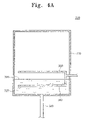
- FIG. 8 a is a bottom view of a gas supply nozzle of the cleaning apparatus shown in FIG. 2 ;
- FIG. 8 b and FIG. 8 c are bottom views of modified examples of the gas supply nozzle
- FIG. 9 a is a side view showing another example of a gas supply nozzle of the cleaning apparatus shown in FIG. 2 ;
- FIG. 9 b and FIG. 9 c are side views of modified examples of the gas supply nozzle
- FIG. 10 a is a cross-sectional view of the gas supply nozzle taken along line C-C of FIG. 9 a;
- FIG. 10 b is a cross-sectional view of a modified example of the gas supply nozzle.
- the cleaning apparatus includes a chamber 100 in which a cleaning process is performed, a bubbler 200 for producing an alcohol vapor and for supplying the alcohol vapor to the chamber 100 , gas supply nozzles 400 for spraying drying gas in the chamber 100 , at least one liquid supply nozzle 500 for supplying liquid into the chamber 100 , a discharge section 600 for discharging the liquid, a gas source 740 for storing the gas supplied to the bubbler 200 and the gas supply nozzles 400 , and an alcohol source 720 for storing the alcohol liquid supplied to the chamber 100 and the bubbler 200 .
- the alcohol is isopropyl alcohol (hereinafter referred to as IPA)
- the drying gas is nitrogen
- the liquid is de-ionized water.
- the chamber 100 comprises a bath 140 that contains the wafers 10 , and a lid 120 for opening and closing over an open top portion of the bath 140 .
- a wafer holder 160 for supporting the wafers 10 is disposed in the bath 140 .
- the wafer holder 160 can be re-positioned in a vertical direction while the de-ionized water is being discharged.
- a first supply pipe 310 extends into the bath 140 from the side thereof. Liquid IPA is supplied from the alcohol source 720 to the chamber 100 through the first supply pipe 310 to form an IPA liquid layer 142 on the surface of the de-ionized water in the bath 140 .
- the lid 120 is semi-cylindrical such that the interior thereof defines a concavity. Accordingly, the wafers 10 can be moved upwardly into the hollow of the lid 120 . At this time, the wafer holder 160 may move upwardly without the de-ionized water being discharged from the bath 140 .
- the height of the chamber 100 is thus at least twice the diameter of the wafers 10 to provide enough space for accommodating the wafers 10 entirely above the surface of the de-ionized water.
- the bubbler 200 includes a vapor generation part 220 for generating the IPA vapor and a spray pipe 240 for spraying the IPA vapor into the chamber 100 .
- the housing 230 of vapor generation part 220 has the shape of a rectangular parallelepiped, and a part of the housing 230 is filled with liquid IPA 222 .
- a second supply pipe 320 is connected to the bottom of the housing 230 .
- a third supply pipe 340 is connected to a side of the housing 230 and is immersed in the liquid IPA 222 .
- a plurality of holes are formed in an upper portion of the third supply pipe 340 .
- Carrier gas such as nitrogen is supplied to the housing 230 through the holes formed in the third supply pipe 340 .
- the carrier gas supplied through the third supply pipe 340 helps the IPA liquid to evaporate and carries the IPA vapor into the chamber 100 .
- the amount of the IPA vapor and the velocity of the IPA vapor are proportional to the amount of the carrier gas that is supplied through the third supply pipe 340 .
- the vapor generation part 220 includes a fourth supply pipe 360 that is branched from the third supply pipe 340 .
- the fourth supply pipe 360 is located over the surface of the liquid IPA 222 .
- a plurality of holes are formed in the fourth supply pipe 360 .
- the carrier gas that flows through the fourth supply pipe 360 only serves to carry the IPA vapor to the chamber 100 , unlike the carrier gas that is supplied through the third supply pipe 340 . Accordingly, the amount of the IPA vapor that is produced and the velocity at which the IPA vapor flows into the chamber 400 are independent, i.e., can be established irrespectively of one another, as opposed to the vapor generation parts of conventional wafer cleaning apparatus.
- the diameter of the third supply pipe 340 may be different from that of the fourth supply pipe 360 .
- the third supply pipe 340 may be provided with a relatively large diameter to produce a large amount of IPA vapor to be moved to the chamber 100 , as shown in FIG. 4B .
- the fourth supply pipe 360 may be provided with a diameter such that the IPA vapor is supplied rapidly to the chamber 100 .
- the third supply pipe 340 may have the same diameter as the fourth supply pipe 360 .
- a flow control valve V is connected to the third or fourth supply pipe 340 , 360 to control the amount of IPA vapor generated or the velocity of the vapor IPA.
- the liquid IPA in the vapor generation part 220 is consumed due to vaporization of the liquid IPA. Therefore, the liquid IPA is continuously supplied to the housing 230 through the second supply pipe 320 to replenish the liquid IPA.
- the spray pipe 240 is inserted through the side of the chamber 100 and the IPA vapor and the carrier gas from the bubbler 200 are supplied into the chamber 100 through the spray pipe 240 . While the IPA vapor and the carrier gas are sprayed to the chamber 100 , condensed liquid of the IPA vapor is formed on the upper portion of the exit end of the spray pipe 240 . If the condensed liquid were to fall into the chamber 100 , the liquid IPA layer 142 formed on the surface of the de-ionized water in the bath 140 would be destroyed. In this case, the drying process using Marangoni principle could not be performed properly until the liquid IPA layer 142 was restored.
- the spray pipe 240 has a liquid retention portion to prevent this problem from occurring.
- the spray pipe 240 has a quadrilateral cross section. More specifically, the spray pipe 240 has an inclined upper wall as the liquid retention portion. The upper wall of the spray pipe 240 is gently inclined downwardly from the exit end of the pipe 240 at which the IPA vapor condenses. Accordingly, the spray pipe 240 is tapered so that condensed liquid flows from the exit end back into the spray pipe 240 .
- the liquid retention portion is a projection 244 in the form of a hook extending from the upper wall at the exit end of the spray pipe 240 back into the spray pipe 240 .
- the condensed liquid thus flows back into the spray pipe 240 along the projection 244 without falling into the chamber 100 .
- the spray pipe may comprise both the inclined upper wall shown in FIG. 5 and the projection 244 shown in FIG. 6 as the liquid retention portion.
- a porous filter 380 is installed on or over the surface of the IPA liquid in the bubbler 200 so as to prevent the IPA mist from being carried into the chamber 100 .
- the porous filter 380 can be heated by a heater (not shown).
- the bubbler 200 may include a connector 260 between the housing 230 and the spray pipe 240 .
- the connector 260 is in the form of a baffle, i.e., has a bend, so as to prevent the IPA mist from being carried to the chamber 100 . Drops of any of the IPA mist will accumulate on the wall of the connector 260 and then fall back into the housing 230 of the vapor generation part 220 without ever having moved into the spray pipe 240 .
- a plurality of liquid supply nozzles 500 extend into the bath 140 to supply liquid used in the cleaning process, such as a process for treating the wafers 10 with a chemical solution or a process for rinsing them.
- the chemical solution may be electrolysis-ionized or hydrofluoric acid that is of a strength sufficient to remove contaminants such as particles, metal, e.g., copper, and natural oxidation layers from the wafers.
- the liquid may be de-ionized water.
- a plurality of holes 510 are formed in each liquid supply nozzle 500 . If the holes 510 were formed in the top of the liquid supply nozzles 500 , the de-ionized water could flow easily into the liquid supply nozzles 500 , giving rise to this potential problem. Any liquid IPA contained in the deionized water inside of a liquid supply nozzle 500 would evaporate after the surface of the de-ionized water became disposed below the liquid supply nozzle 500 when the de-ionized water is discharged from the bath 140 . The evaporated IPA contains little, if any, de-ionized water, and thereby would surely contaminate the wafers 10 . However, in the present invention, the holes 510 are formed in a side of each liquid supply nozzle 500 . This prevents the de-ionized water containing liquid IPA in the bath 140 from flowing into the liquid supply nozzles 500 .
- the de-ionized water containing the liquid IPA is discharged through the discharge section 600 .
- the discharge section 600 is connected to the bottom of the bath 140 .
- the discharge section 600 includes a first discharge pipe 620 and a second discharge pipe 640 .
- the first discharge pipe 620 is connected perpendicularly with the bottom of the bath 140 and the second discharge pipe 640 extends from the first discharge pipe 620 horizontally alongside the bottom of the chamber 100 .
- a directional flow control valve 660 is connected to the pipes 620 , 640 at the location where the second discharge pipe 640 branches from the first discharge pipe 620 to select the pipe through which the de-ionized water is discharged.
- the de-ionized water is discharged through the second discharge pipe 640 while at least a portion of the wafers 10 is immersed in the de-ionized water.
- a pump is connected to the second discharge pipe 640 for controlling the rate of discharge.
- the de-ionized water is discharged through the first discharge pipe 620 by gravity once the wafers 10 are entirely located above to the surface of the de-ionized water.
- the cleaning apparatus of the present invention does not have an exhaust hole for exhausting the nitrogen gas or the IPA vapor. Rather, in the present invention, the nitrogen gas and the IPA vapor are exhausted through the second discharge pipe 640 . This prevents outside air from invading the chamber 100 through a dedicated exhaust hole.
- drying gas such as heated nitrogen
- the drying gas is supplied to the chamber 100 through a plurality of gas supply nozzles 400 installed on an upper surface of the lid 120 .
- a heater 760 is installed in the gas supply line extending between the gas source 760 (gas supply tank) and the gas supply nozzles 400 to heat the drying gas. It is very important that the drying gas is supplied uniformly to all the wafers 10 .
- each gas supply nozzle 400 has a plurality of circular spray openings spaced therealong from one end thereof to the other. For instance, when a set of N wafers 10 is put in the wafer holder 160 , the openings are located over a top portion of and span the first wafer 10 to N-th wafer 10 .
- the spray openings 420 in the gas supply nozzle 400 have different sizes to ensure that the amount of nitrogen supplied to the N-th wafer 10 is the same as the amount of nitrogen supplied to the first wafer 10 .
- the size of openings 420 increases as the distance from the side of the chamber 100 from which the gas supply nozzle 400 extends increases.
- the spray openings 420 are formed at different intervals to ensure that the amount of the nitrogen gas supplied to the N-th wafer 10 is the same as the amount of nitrogen gas supplied to the first wafer 10 .
- the intervals between adjacent openings 420 increase as the distance from the side of the chamber 100 from which the gas supply nozzle 400 extends increases.
- the gas supply nozzle 400 may have a slit-type of opening 440 instead of a plurality of discrete spray openings.
- the length of the opening 440 spans the set of wafers 10 , i.e., extends from the top of the first wafer 10 to the top of N-th wafer 10 .
- the slit-type of opening 440 may flare outwardly at both the sides and the ends thereof so that the nitrogen is sprayed over all of the wafers 10 .
- the width of the slit-type of opening 440 may increase gradually as the distance from the side of the chamber 100 from which the gas supply nozzle 400 extends increases.
- the wafers 10 are cleaned as follows. First, the rinse (or chemical treatment) process is performed with de-ionized water (or a chemical solution) in the bath 140 . For purposes of explanation, only the rinse process will be referred to.
- the de-ionized water with liquid IPA in the bath 140 is slowly discharged through the second discharge pipe 640 . IPA vapor is sprayed into the chamber 100 through the spray pipe 240 while the de-ionized water is being slowly discharged.
- the wafers 10 may be moved upwardly during the discharging of the de-ionized water to speed up the overall cleaning process.
- the de-ionized water is quickly discharged through the first discharge pipe 620 once the wafers 10 have passed completely through the surface of the de-ionized water.
- the heated nitrogen gas is sprayed onto the wafers 10 in the bath 140 through the gas supply nozzles 400 in order to remove the de-ionized water and the liquid IPA adhering to the wafers 10 .
- a condensed liquid of IPA formed at the exit of a spray pipe of a bubbler is retained within the spray pipe. Therefore, the IPA liquid layer in the bath 140 is not destroyed by the condensed liquid.
- the holes of the gas supply nozzle 400 have different diameters or are spaced at different intervals. Therefore, the same amount of the nitrogen is supplied to all of the wafers 10 disposed in the bath 140 .
Abstract
An apparatus for cleaning semiconductor wafers includes a chamber, a bubbler having a vapor generating part for generating alcohol vapor and a spray pipe for spraying the alcohol vapor into the chamber, a gas supply nozzle for spraying gas into the chamber to dry the wafers, a liquid supply nozzle for supplying cleaning liquid into the chamber and a discharge system. The spray pipe of the bubbler has a liquid retention portion that keeps condensate of the alcohol vapor from issuing into the chamber. The gas supply nozzle has a spray outlet configured to spray the same amount of the drying gas onto all of the wafers in the chamber. The liquid supply nozzle has liquid supply openings only in a side portion thereof so that liquid alcohol will not become trapped therein.
Description
1. Field of the Invention
The present invention relates to an apparatus for manufacturing semiconductor devices. More particularly, the present invention relates to an apparatus for cleaning semiconductor wafers in accordance with the Marangoni principle.
2. Description of the Related Art
When a semiconductor wafer is manufactured into integrated circuit (IC) devices, the wafer is subjected to a series of semiconductor device manufacturing processes such as photolithography, chemical or physical vapor deposition and plasma etching processes. Foreign materials, such as residual chemicals, small particles, and other contaminants, may remain on the surface of the wafer after these processes are carried out. The foreign materials must be removed from the surface of the wafer to assure the quality of the IC devices.
A wafer cleaning process may include both rinsing and drying the wafer to remove foreign materials. A silicon wafer is generally rinsed using de-ionized water. However, the de-ionized water is an aggressive solvent against silicon and will thus eventually dissolve the silicon wafer. Accordingly, the wafer must be completely dried after being rinsed with the de-ionized water.
There are a number of semiconductor wafer cleaning systems commercially available. Recently, wafer cleaning systems based on the Marangoni principle have been widely used in the art. The Marangoni principle is based on the fact that when there is a liquid region wherein two different surface tensions exist, liquid flows from the region of the lower surface tension to the region of the higher surface tension. In Marangoni principle-based wafer cleaning systems, de-ionized water is typically used to rinse the wafer, and isopropyl alcohol (IPA) is typically used to dry the deionized water. The IPA has a lower surface tension than does the de-ionized water. Examples of conventional wafer cleaning systems using the Marangoni principle are disclosed in U.S. Pat. Nos. 5,569,330, 5,807,439, 6,027,574, and 6,354,313. These systems each include a chamber to accommodate wafers, and a bubbler for generating IPA vapor.
An object of the present invention is to provide a wafer cleaning apparatus that uses the Marangoni principle, and which apparatus exhibits better wafer cleaning characteristics than do previous apparatus.
A specific object of the present invention is to provide a wafer cleaning apparatus that uses the Marangoni principle, and which apparatus prevents condensed alcohol from issuing into the chamber of the apparatus from an exit end of a spray pipe of a bubbler that sprays alcohol vapor into the cleaning and drying chamber.
Yet another object of the present invention is to provide a wafer cleaning apparatus that uses the Marangoni principle, and which apparatus prevents alcohol existing in the form of a mist within the bubbler from being introduced into the cleaning and drying chamber.
Still another aspect of the present invention is to provide a wafer cleaning apparatus that uses the Marangoni principle, and by which the amount of alcohol vapor introduced into the cleaning and drying chamber and the velocity at which the alcohol vapor is introduced into the chamber can be established independently of one another.
Another specific object of the present invention is to provide a wafer cleaning apparatus that uses the Marangoni principle, and which apparatus sprays drying gas uniformly onto a plurality of wafers in the chamber of the apparatus.
Another aspect of the present invention is to provide a wafer cleaning apparatus that uses the Marangoni principle, and which apparatus prevents the wafers from being contaminated when the level of cleaning liquid falls below the level of the liquid supply nozzle(s), such as when the cleaning liquid is discharged.
The apparatus for cleaning a semiconductor wafer of the present invention, comprises. a chamber in which a wafer cleaning process is performed, and a bubbler for producing alcohol (e.g., isopropyl alcohol) vapor. The chamber includes a bath that contains a wafer holder, and a lid that covers the bath. The height of the chamber is at least twice the diameter of the wafers to be cleaned therein. A first supply pipe is disposed at one side of the bath to supply liquid alcohol to the chamber. The liquid alcohol forms a layer on the de-ionized water in chamber. The bubbler includes a vapor generating part for generating the alcohol vapor, and a spray pipe for spraying the alcohol vapor and carrier gas for the alcohol vapor into the chamber.
According to an aspect of the present invention, the spray pipe has a liquid retention portion. This portion of the spray pipe retains liquid, namely the condensate of the alcohol vapor formed at an exit end of the spray pipe, within the spray pipe.
According to another aspect of the present invention, the vapor generating part comprises a housing, a second supply pipe for supplying liquid alcohol to the housing such that the housing becomes partially filled with the liquid alcohol, a third supply pipe submerged in the liquid alcohol inside the housing for supplying the carrier gas into the housing at a level below the surface of the liquid alcohol, and a fourth supply pipe for supplying the carrier gas to the housing at a level above the surface of the liquid alcohol in the housing.
The bubbler may further include a baffle in the form of a connector having a bend that is disposed between the spray pipe and the vapor generating part, and/or porous filter disposed in the vapor generating part. The bend of the connector and the filter serve to prevent the alcohol in the form of a mist from being carried to the spray pipe.
According to yet another aspect of the present invention, the cleaning apparatus comprises at least one gas supply nozzle for spraying drying gas uniformly over a number wafers disposed in the chamber. The gas supply nozzle includes an inlet end adjacent a side of the cleaning and drying chamber, a nozzle body extending from the inlet end, and a spray outlet spanning at least the length over which the number of wafers can be arranged in the chamber. The spray outlet may take the form of a plurality of circular openings having different sizes or spaced from one another by different intervals. Alternatively, the spray outlet of the gas supply nozzle may have the form of a slit extending longitudinally in the nozzle body. The slit is preferably flared outwardly at both ends and/or both sides thereof such that the outer opening of the slit is larger than the inner opening thereof. In addition, the width of the slit may increase along the length of the nozzle body in a direction from the side of the chamber where the inlet end of the nozzle is located.
The cleaning apparatus further includes at least one liquid supply nozzle disposed below a wafer holder for supplying liquid for cleaning the wafer into the chamber. The nozzle body of the liquid supply nozzle has a top portion that faces upwardly towards the wafer holder, and a side portion that faces laterally in a direction perpendicular to the top portion. According to still yet another aspect of the present invention, liquid supply openings of the supply nozzle are provided only in the side portion of the nozzle body. Thus, any liquid IPA on the surface of the cleaning liquid will not be trapped in the liquid supply nozzle during the discharging of the cleaning liquid from the chamber.
The discharge system includes a first discharge pipe for draining the liquid using gravity after the wafers are brought above the surface of the cleaning liquid, and a second discharge pipe for draining the liquid while a portion of the wafers are submerged in the liquid. A pump is connected to the second discharge pipe to control the velocity at which the liquid is drained. Preferably, the alcohol vapor and carrier gas in the chamber are exhausted through the second discharge pipe.
The above and other objects, features, and advantages of the present invention will be more readily apparent from the following detailed description of preferred embodiments thereof when taken together with the accompanying drawings in which:
The present invention will now be described more fully hereinafter with reference to the attached figures, in which preferred embodiments of the invention are shown.
Referring to FIG. 1 and FIG. 2 , the cleaning apparatus includes a chamber 100 in which a cleaning process is performed, a bubbler 200 for producing an alcohol vapor and for supplying the alcohol vapor to the chamber 100, gas supply nozzles 400 for spraying drying gas in the chamber 100, at least one liquid supply nozzle 500 for supplying liquid into the chamber 100, a discharge section 600 for discharging the liquid, a gas source 740 for storing the gas supplied to the bubbler 200 and the gas supply nozzles 400, and an alcohol source 720 for storing the alcohol liquid supplied to the chamber 100 and the bubbler 200.
The alcohol is isopropyl alcohol (hereinafter referred to as IPA), the drying gas is nitrogen, and the liquid is de-ionized water.
The chamber 100 comprises a bath 140 that contains the wafers 10, and a lid 120 for opening and closing over an open top portion of the bath 140. A wafer holder 160 for supporting the wafers 10 is disposed in the bath 140. The wafer holder 160 can be re-positioned in a vertical direction while the de-ionized water is being discharged. A first supply pipe 310 extends into the bath 140 from the side thereof. Liquid IPA is supplied from the alcohol source 720 to the chamber 100 through the first supply pipe 310 to form an IPA liquid layer 142 on the surface of the de-ionized water in the bath 140.
The lid 120 is semi-cylindrical such that the interior thereof defines a concavity. Accordingly, the wafers 10 can be moved upwardly into the hollow of the lid 120. At this time, the wafer holder 160 may move upwardly without the de-ionized water being discharged from the bath 140. The height of the chamber 100 is thus at least twice the diameter of the wafers 10 to provide enough space for accommodating the wafers 10 entirely above the surface of the de-ionized water.
Referring to FIG. 3 and FIG. 4A , the bubbler 200 includes a vapor generation part 220 for generating the IPA vapor and a spray pipe 240 for spraying the IPA vapor into the chamber 100. The housing 230 of vapor generation part 220 has the shape of a rectangular parallelepiped, and a part of the housing 230 is filled with liquid IPA 222. A second supply pipe 320 is connected to the bottom of the housing 230. A third supply pipe 340 is connected to a side of the housing 230 and is immersed in the liquid IPA 222. A plurality of holes are formed in an upper portion of the third supply pipe 340. Carrier gas, such as nitrogen, is supplied to the housing 230 through the holes formed in the third supply pipe 340. The carrier gas supplied through the third supply pipe 340 helps the IPA liquid to evaporate and carries the IPA vapor into the chamber 100. The amount of the IPA vapor and the velocity of the IPA vapor are proportional to the amount of the carrier gas that is supplied through the third supply pipe 340.
The vapor generation part 220 includes a fourth supply pipe 360 that is branched from the third supply pipe 340. The fourth supply pipe 360 is located over the surface of the liquid IPA 222. A plurality of holes are formed in the fourth supply pipe 360. The carrier gas that flows through the fourth supply pipe 360 only serves to carry the IPA vapor to the chamber 100, unlike the carrier gas that is supplied through the third supply pipe 340. Accordingly, the amount of the IPA vapor that is produced and the velocity at which the IPA vapor flows into the chamber 400 are independent, i.e., can be established irrespectively of one another, as opposed to the vapor generation parts of conventional wafer cleaning apparatus.
For example, the diameter of the third supply pipe 340 may be different from that of the fourth supply pipe 360. The third supply pipe 340 may be provided with a relatively large diameter to produce a large amount of IPA vapor to be moved to the chamber 100, as shown in FIG. 4B . The fourth supply pipe 360 may be provided with a diameter such that the IPA vapor is supplied rapidly to the chamber 100. Alternatively, the third supply pipe 340 may have the same diameter as the fourth supply pipe 360. In this case, as shown in FIG. 4C , a flow control valve V is connected to the third or fourth supply pipe 340, 360 to control the amount of IPA vapor generated or the velocity of the vapor IPA.
The liquid IPA in the vapor generation part 220 is consumed due to vaporization of the liquid IPA. Therefore, the liquid IPA is continuously supplied to the housing 230 through the second supply pipe 320 to replenish the liquid IPA.
Referring again to FIG. 1 , the spray pipe 240 is inserted through the side of the chamber 100 and the IPA vapor and the carrier gas from the bubbler 200 are supplied into the chamber 100 through the spray pipe 240. While the IPA vapor and the carrier gas are sprayed to the chamber 100, condensed liquid of the IPA vapor is formed on the upper portion of the exit end of the spray pipe 240. If the condensed liquid were to fall into the chamber 100, the liquid IPA layer 142 formed on the surface of the de-ionized water in the bath 140 would be destroyed. In this case, the drying process using Marangoni principle could not be performed properly until the liquid IPA layer 142 was restored. The spray pipe 240 has a liquid retention portion to prevent this problem from occurring.
According to one example shown in FIG. 5 , the spray pipe 240 has a quadrilateral cross section. More specifically, the spray pipe 240 has an inclined upper wall as the liquid retention portion. The upper wall of the spray pipe 240 is gently inclined downwardly from the exit end of the pipe 240 at which the IPA vapor condenses. Accordingly, the spray pipe 240 is tapered so that condensed liquid flows from the exit end back into the spray pipe 240.
Another example of the liquid retention portion is shown in FIG. 6 . In this example, the liquid retention portion is a projection 244 in the form of a hook extending from the upper wall at the exit end of the spray pipe 240 back into the spray pipe 240. The condensed liquid thus flows back into the spray pipe 240 along the projection 244 without falling into the chamber 100.
If desired, the spray pipe may comprise both the inclined upper wall shown in FIG. 5 and the projection 244 shown in FIG. 6 as the liquid retention portion.
In addition, part of the IPA exists in the form of a mist. A porous filter 380 is installed on or over the surface of the IPA liquid in the bubbler 200 so as to prevent the IPA mist from being carried into the chamber 100. The porous filter 380 can be heated by a heater (not shown).
Referring next to FIG. 7 , the bubbler 200 may include a connector 260 between the housing 230 and the spray pipe 240. The connector 260 is in the form of a baffle, i.e., has a bend, so as to prevent the IPA mist from being carried to the chamber 100. Drops of any of the IPA mist will accumulate on the wall of the connector 260 and then fall back into the housing 230 of the vapor generation part 220 without ever having moved into the spray pipe 240.
A plurality of liquid supply nozzles 500 extend into the bath 140 to supply liquid used in the cleaning process, such as a process for treating the wafers 10 with a chemical solution or a process for rinsing them. The chemical solution may be electrolysis-ionized or hydrofluoric acid that is of a strength sufficient to remove contaminants such as particles, metal, e.g., copper, and natural oxidation layers from the wafers. When the cleaning process is a rinsing process, the liquid may be de-ionized water.
A plurality of holes 510 are formed in each liquid supply nozzle 500. If the holes 510 were formed in the top of the liquid supply nozzles 500, the de-ionized water could flow easily into the liquid supply nozzles 500, giving rise to this potential problem. Any liquid IPA contained in the deionized water inside of a liquid supply nozzle 500 would evaporate after the surface of the de-ionized water became disposed below the liquid supply nozzle 500 when the de-ionized water is discharged from the bath 140. The evaporated IPA contains little, if any, de-ionized water, and thereby would surely contaminate the wafers 10. However, in the present invention, the holes 510 are formed in a side of each liquid supply nozzle 500. This prevents the de-ionized water containing liquid IPA in the bath 140 from flowing into the liquid supply nozzles 500.
The de-ionized water containing the liquid IPA is discharged through the discharge section 600. The discharge section 600 is connected to the bottom of the bath 140. The discharge section 600 includes a first discharge pipe 620 and a second discharge pipe 640. The first discharge pipe 620 is connected perpendicularly with the bottom of the bath 140 and the second discharge pipe 640 extends from the first discharge pipe 620 horizontally alongside the bottom of the chamber 100. A directional flow control valve 660 is connected to the pipes 620, 640 at the location where the second discharge pipe 640 branches from the first discharge pipe 620 to select the pipe through which the de-ionized water is discharged.
The de-ionized water is discharged through the second discharge pipe 640 while at least a portion of the wafers 10 is immersed in the de-ionized water. A pump is connected to the second discharge pipe 640 for controlling the rate of discharge. The de-ionized water is discharged through the first discharge pipe 620 by gravity once the wafers 10 are entirely located above to the surface of the de-ionized water. Unlike conventional wafer cleaning apparatuses, the cleaning apparatus of the present invention does not have an exhaust hole for exhausting the nitrogen gas or the IPA vapor. Rather, in the present invention, the nitrogen gas and the IPA vapor are exhausted through the second discharge pipe 640. This prevents outside air from invading the chamber 100 through a dedicated exhaust hole.
After all of the de-ionized water is drained, the water and the liquid IPA that are adhered to the wafer 10 should be removed. Drying gas, such as heated nitrogen, is used for this purpose. The drying gas is supplied to the chamber 100 through a plurality of gas supply nozzles 400 installed on an upper surface of the lid 120. A heater 760 is installed in the gas supply line extending between the gas source 760 (gas supply tank) and the gas supply nozzles 400 to heat the drying gas. It is very important that the drying gas is supplied uniformly to all the wafers 10.
Referring to FIG. 8 a, each gas supply nozzle 400 has a plurality of circular spray openings spaced therealong from one end thereof to the other. For instance, when a set of N wafers 10 is put in the wafer holder 160, the openings are located over a top portion of and span the first wafer 10 to N-th wafer 10.
Referring to FIG. 8 b, which shows a modified example of the gas supply nozzle 400, the spray openings 420 in the gas supply nozzle 400 have different sizes to ensure that the amount of nitrogen supplied to the N-th wafer 10 is the same as the amount of nitrogen supplied to the first wafer 10. In particular, the size of openings 420 increases as the distance from the side of the chamber 100 from which the gas supply nozzle 400 extends increases.
Referring to FIG. 8 c, which shows still another modified example of the gas supply nozzle 400, the spray openings 420 are formed at different intervals to ensure that the amount of the nitrogen gas supplied to the N-th wafer 10 is the same as the amount of nitrogen gas supplied to the first wafer 10. Specifically, the intervals between adjacent openings 420 increase as the distance from the side of the chamber 100 from which the gas supply nozzle 400 extends increases.
Referring to FIG. 9 a and FIG. 10 a, the gas supply nozzle 400 may have a slit-type of opening 440 instead of a plurality of discrete spray openings. In this embodiment, the length of the opening 440 spans the set of wafers 10, i.e., extends from the top of the first wafer 10 to the top of N-th wafer 10.
Referring to FIG. 9 b and FIG. 10 b, the slit-type of opening 440 may flare outwardly at both the sides and the ends thereof so that the nitrogen is sprayed over all of the wafers 10.
Referring to FIG. 9 c, the width of the slit-type of opening 440 may increase gradually as the distance from the side of the chamber 100 from which the gas supply nozzle 400 extends increases.
The wafers 10 are cleaned as follows. First, the rinse (or chemical treatment) process is performed with de-ionized water (or a chemical solution) in the bath 140. For purposes of explanation, only the rinse process will be referred to. The de-ionized water with liquid IPA in the bath 140 is slowly discharged through the second discharge pipe 640. IPA vapor is sprayed into the chamber 100 through the spray pipe 240 while the de-ionized water is being slowly discharged. The wafers 10 may be moved upwardly during the discharging of the de-ionized water to speed up the overall cleaning process. The de-ionized water is quickly discharged through the first discharge pipe 620 once the wafers 10 have passed completely through the surface of the de-ionized water. Then the heated nitrogen gas is sprayed onto the wafers 10 in the bath 140 through the gas supply nozzles 400 in order to remove the de-ionized water and the liquid IPA adhering to the wafers 10.
According to the present invention, a condensed liquid of IPA formed at the exit of a spray pipe of a bubbler is retained within the spray pipe. Therefore, the IPA liquid layer in the bath 140 is not destroyed by the condensed liquid.
Furthermore, in the present invention, the holes of the gas supply nozzle 400 have different diameters or are spaced at different intervals. Therefore, the same amount of the nitrogen is supplied to all of the wafers 10 disposed in the bath 140.
Finally, although the present invention has been described in connection with the preferred embodiments thereof, various changes and modifications can be made thereto without departing from the true spirit and scope of the invention as defined by the appended claims.
Claims (17)
1. An apparatus for cleaning semiconductor wafers, comprising:
a chamber having a bath, and a lid that covers said bath;
a source of liquid alcohol, and a source of a carrier gas;
a bubbler having a vapor generating part comprising a housing in which alcohol vapor used to dry wafers in said chamber is generated, and a spray pipe connected to the housing of said vapor generating part; and
a second supply pipe connecting said source of liquid alcohol to said housing and through which liquid alcohol is supplied into the housing such that a lower portion of the housing becomes filled with the liquid alcohol,
wherein the vapor generating part of said bubbler further comprises a third supply pipe in fluid communication with said source of carrier gas so as to receive carrier gas from said source of the carrier gas, and said third supply pipe having an end disposed in said lower portion of the housing such that said end of the third supply pipe will be submerged in the liquid alcohol that fills the lower portion of said housing, the end of said third supply pipe having an outlet in open fluid communication with said lower portion of the housing and through which outlet the carrier gas is supplied into liquid alcohol filling the lower portion of said housing so that the carrier gas will bubble through the liquid alcohol and thereby generate alcohol vapor from the liquid alcohol, and
said spray pipe extends into said chamber and has an exit end from which the alcohol vapor and the carrier gas issue in said chamber, and liquid retention means for preventing condensate of alcohol vapor, formed at the interior of said spray pipe within the chamber, from issuing from the exit end of the spray pipe.
2. An apparatus for cleaning semiconductor wafers, comprising:
a chamber having a bath, and a lid that covers said bath;
a source of liquid alcohol, and a source of a carrier gas;
a bubbler having a vapor generating part comprising a housing in which alcohol vapor used to dry wafers in said chamber is generated, and a spray pipe connected to the housing of said vapor generating part; and
a second supply pipe connecting said source of liquid alcohol to said housing and through which liquid alcohol is supplied into the housing such that a lower portion of the housing becomes filled with the liquid alcohol,
wherein the vapor generating part of said bubbler further comprises a third supply pipe in fluid communication with said source of carrier gas so as to receive carrier gas from said source of the carrier gas, and said third supply pipe having an end disposed in said lower portion of the housing such that said end of the third supply pipe will be submerged in the liquid alcohol that fills the lower portion of said housing, the end of said third supply pipe having an outlet in open fluid communication with said lower portion of the housing and through which outlet the carrier gas is supplied into liquid alcohol filling the lower portion of said housing so that the carrier gas will bubble through the liquid alcohol and thereby generate alcohol vapor from the liquid alcohol, and
said spray pipe extends into said chamber, said spray pipe having an exit end located in said chamber and from which the alcohol vapor and the carrier gas issue in said chamber, and an upper wall at the top thereof, said upper wall terminating at said exit end within the chamber, and said upper wall being inclined downwardly beginning within the chamber and in a direction away from said exit end, whereby the upper wall prevents condensate of the alcohol vapor formed at the interior of said spray pipe within the chamber from issuing from the exit end of the spray pipe.
3. An apparatus for cleaning semiconductor wafers, comprising:
a chamber having a bath, and a lid that covers said bath;
a source of liquid alcohol, and a source of a carrier gas;
a bubbler having a vapor generating part comprising a housing in which alcohol vapor used to dry wafers in said chamber is generated, and a spray pipe connected to the housing of said vapor generating part; and
a second supply pipe connecting said source of liquid alcohol to said housing and through which liquid alcohol is supplied into the housing such that a lower portion of the housing becomes filled with the liquid alcohol,
wherein the vapor generating part of said bubbler further comprises a third supply pipe in fluid communication with said source of carrier gas so as to receive carrier gas from said source of the carrier gas, and said third supply pipe having an end disposed in said lower portion of the housing such that said end of the third supply pipe will be submerged in the liquid alcohol that fills the lower portion of said housing, the end of said third supply pipe having an outlet in open fluid communication with said lower portion of the housing and through which outlet the carrier gas is supplied into liquid alcohol filling the lower portion of said housing so that the carrier gas will bubble through the liquid alcohol and thereby generate alcohol vapor from the liquid alcohol, and
said spray pipe extends into said chamber, and said spray pipe has an upper wall at the top thereof, and a projection disposed at the exit end of the spray pipe, the projection extending downwardly and inwardly, with respect to the interior of the spray pipe, from said upper wall, whereby the projection prevents condensate of the alcohol vapor formed at the interior of said spray pipe within the chamber from issuing from the exit end of the spray pipe.
4. The apparatus of claim 1 , and further comprising a first supply pipe connected to said source of liquid alcohol and extending into said chamber so as to supply the liquid alcohol into the chamber.
5. The apparatus of claim 1 , wherein said source of liquid alcohol is a source of isopropyl alcohol and said source of carrier gas is a source of nitrogen gas.
6. The apparatus of claim 1 , wherein said vapor generating part further comprises a fourth supply pipe connected to said source of carrier gas and having an end disposed in said housing at a location above said lower portion of the housing such that said end of the fourth supply pipe will be disposed above the liquid alcohol filling the lower portion of the housing, whereby said fourth supply pipe supplies carrier gas into the housing to carry the alcohol vapor through said spray pipe and into the chamber.
7. The apparatus of claim 1 , wherein said spray pipe extends generally horizontally through the side wall of the chamber, the housing of said vapor generating part extends generally vertically alongside the chamber, and said bubbler further comprises a connector having a bend therein that extends between and connects said spray pipe and the housing of said vapor generating part to prevent alcohol vapor in the form of a mist from flowing from said housing to said spray pipe.
8. The apparatus of claim 1 , wherein said bubbler further comprises a porous filter disposed in said vapor generating part to prevent alcohol vapor in the form of a mist from flowing from said housing to said spray pipe.
9. An apparatus for cleaning semiconductor wafers, comprising:
a chamber having a bath, and a lid that covers said bath;
a source of liquid alcohol, and a source of a carrier gas; and
a vapor generator connected to said sources of liquid alcohol and carrier gas, said vapor generator including a housing in which alcohol vapor used to dry wafers in said chamber is generated, and a spray pipe having first end portion disposed outside the chamber and connected to the housing such that alcohol vapor generated in the housing flows into the spray pipe, said spray pipe having a generally horizontal second end portion that is disposed within the chamber and terminates within the chamber at an exit end of the spray pipe in the axial direction of the spray pipe, the exit end of the spray pipe being open so that the alcohol vapor and the carrier gas issue from the exit end of the spray pipe while flowing generally horizontally in the axial direction of the spray pipe, wherein the spray pipe includes a liquid retention means for preventing condensate of the alcohol vapor, formed at the interior of said spray pipe within the chamber, from issuing from the exit end of the spray pipe.
10. The apparatus of claim 9 , wherein said said spray pipe has an upper wall at the top thereof, the upper wall terminating at the exit end of the spray pipe within said chamber, and said upper wall being inclined downwardly beginning within the chamber in a direction away from said exit end of the spray pipe, whereby the upper wall prevents condensate of the alcohol vapor formed at the interior of said spray pipe within the chamber from issuing from the exit end of the spray pipe.
11. The apparatus of claim 9 , wherein said spray pipe has an upper wall at the top thereof, and a projection disposed at the exit end of the spray pipe, the projection extending downwardly and inwardly, with respect to the interior of the spray pipe, from said upper wall, whereby the projection prevents condensate of the alcohol vapor formed at the interior of said spray pipe within the chamber from issuing from the exit end of the spray pipe.
12. The apparatus of claim 9 , and further comprising a first supply pipe connected to said source of liquid alcohol and extending into said chamber so as to supply the liquid alcohol into the chamber.
13. The apparatus of claim 9 , wherein said source of liquid alcohol is a source of isopropyl alcohol and said source of carrier gas is a source of nitrogen gas.
14. The apparatus of claim 9 , and further comprising a second supply pipe connecting said source of liquid alcohol to said housing and through which liquid alcohol is supplied into the housing such that a lower portion of the housing becomes filled with the liquid alcohol, and wherein the vapor generator is a bubbler that further comprises a third and fourth supply pipes in fluid communication with said source of carrier gas so as to receive carrier gas from said source of the carrier gas, said third supply pipe having an end disposed in said lower portion of the housing such that said end of the third supply pipe will be submerged in the liquid alcohol that fills the lower portion of said housing, the end of said third supply pipe having an outlet in open fluid communication with said lower portion of the housing and through which outlet the carrier gas is supplied into liquid alcohol filling the lower portion of said housing so that the carrier gas will bubble through the liquid alcohol and thereby generate alcohol vapor from the liquid alcohol, and said fourth supply pipe having an end disposed in said housing at a location above the lower portion of said housing such that said end of the fourth supply pipe will be disposed above the liquid alcohol filling the lower portion the housing, whereby said fourth supply pipe supplies carrier gas into the housing to carry vapor of the liquid alcohol through said spray pipe and into the chamber.
15. The apparatus of claim 9 , wherein said housing extends generally vertically alongside the chamber, and said vapor generator further comprises a connector having a bend therein that extends between and connects said spray pipe and the housing to prevent alcohol vapor in the form of a mist from flowing from said housing to said spray pipe.
16. The apparatus of claim 9 , wherein said bubbler further comprises a porous filter disposed in said vapor generating part to prevent alcohol vapor in the form of a mist from flowing from said housing to said spray pipe.
17. The apparatus of claim 1 , wherein said chamber has an upper portion constituted by a side wall, and a lower portion constituted by said bath, the lid is disposed on said upper portion, and said spray pipe extends through the side wall and into the upper portion of said chamber at a location beneath said lid.
Applications Claiming Priority (2)
| Application Number | Priority Date | Filing Date | Title |
|---|---|---|---|
| KR10-2002-0036489A KR100481309B1 (en) | 2002-06-27 | 2002-06-27 | Apparatus for drying semiconductor substrate |
| KR2002-36489 | 2002-06-27 |
Publications (2)
| Publication Number | Publication Date |
|---|---|
| US20040000330A1 US20040000330A1 (en) | 2004-01-01 |
| US7255115B2 true US7255115B2 (en) | 2007-08-14 |
Family
ID=29774961
Family Applications (1)
| Application Number | Title | Priority Date | Filing Date |
|---|---|---|---|
| US10/410,278 Expired - Fee Related US7255115B2 (en) | 2002-06-27 | 2003-04-10 | Apparatus for cleaning semiconductor wafers |
Country Status (2)
| Country | Link |
|---|---|
| US (1) | US7255115B2 (en) |
| KR (1) | KR100481309B1 (en) |
Cited By (5)
| Publication number | Priority date | Publication date | Assignee | Title |
|---|---|---|---|---|
| US20070131254A1 (en) * | 2005-12-13 | 2007-06-14 | Industrial Technology Research Institute | Washing apparatus with bubbling reaction and a washing method of using bubbling reaction |
| US20070175062A1 (en) * | 2004-04-02 | 2007-08-02 | Tokyo Electron Limited | Substrate processing system, substrate processing method, recording medium and software |
| US20100307416A1 (en) * | 2009-06-04 | 2010-12-09 | Sang Ki Park | Chemical Vapor Deposition Apparatus |
| US11485647B2 (en) * | 2019-05-23 | 2022-11-01 | Bsh Home Appliances Corporation | Changeable water filter in combination with a mixing valve for pretreatment of water in a home appliance and method of pretreating water |
| US11839839B2 (en) * | 2018-12-13 | 2023-12-12 | Xia Tai Xin Semiconductor (Qing Dao) Ltd. | Apparatus and system for filtrating liquid |
Families Citing this family (9)
| Publication number | Priority date | Publication date | Assignee | Title |
|---|---|---|---|---|
| JP2004140196A (en) * | 2002-10-17 | 2004-05-13 | Nec Electronics Corp | Manufacturing method of semiconductor device and substrate washing equipment |
| KR100672942B1 (en) * | 2004-10-27 | 2007-01-24 | 삼성전자주식회사 | Apparatus and method for drying substrates used in manufacturing semiconductor devices |
| WO2007124166A2 (en) * | 2006-04-22 | 2007-11-01 | Gens Timothy H | Devices and methods for drying objects using aerosols |
| JP4762822B2 (en) | 2006-08-03 | 2011-08-31 | 東京エレクトロン株式会社 | Chemical liquid mixing method and chemical liquid mixing apparatus |
| KR100781890B1 (en) * | 2006-12-26 | 2007-12-03 | 동부일렉트로닉스 주식회사 | Washing device |
| US8221557B2 (en) * | 2007-07-06 | 2012-07-17 | Micron Technology, Inc. | Systems and methods for exposing semiconductor workpieces to vapors for through-hole cleaning and/or other processes |
| CN106269690B (en) * | 2016-08-31 | 2019-07-26 | 湘潭大众整流器制造有限公司 | A kind of anode plate cleaning case |
| IT201900002485A1 (en) * | 2019-02-20 | 2020-08-20 | Protim S R L | PROCESS OF COATING OF PIECES |
| US20210384049A1 (en) * | 2020-06-04 | 2021-12-09 | Tokyo Electron Limited | System and Method for Wet Chemical Etching in Semiconductor Processing |
Citations (15)
| Publication number | Priority date | Publication date | Assignee | Title |
|---|---|---|---|---|
| US5014727A (en) * | 1989-02-27 | 1991-05-14 | Seiichiro Aigo | Bubbler device for washing semiconductor materials |
| US5569330A (en) | 1994-04-15 | 1996-10-29 | Steag Microtech Gmbh Donaueschingen | Method and device for chemically treating substrates |
| US5715612A (en) * | 1995-08-17 | 1998-02-10 | Schwenkler; Robert S. | Method for precision drying surfaces |
| US5807439A (en) * | 1997-09-29 | 1998-09-15 | Siemens Aktiengesellschaft | Apparatus and method for improved washing and drying of semiconductor wafers |
| US5813133A (en) * | 1996-09-04 | 1998-09-29 | Minnesota Mining And Manufacturing Company | Coated substrate drying system with magnetic particle orientation |
| US5932027A (en) * | 1994-11-14 | 1999-08-03 | Yieldup International | Cleaning and drying photoresist coated wafers |
| US6045621A (en) * | 1998-10-26 | 2000-04-04 | Scd Mountain View, Inc. | Method for cleaning objects using a fluid charge |
| KR20000073750A (en) | 1999-05-13 | 2000-12-05 | 윤종용 | Marangoni type dry system for drying a wafer |
| KR20010112344A (en) | 2000-01-17 | 2001-12-20 | 추후제출 | Method and device for drying substrate |
| US6354313B1 (en) | 1998-03-05 | 2002-03-12 | Micron Technology, Inc. | Apparatus for rinsing and drying semiconductor wafers in a chamber with a movable side wall |
| US20020032973A1 (en) * | 2000-08-03 | 2002-03-21 | Jung Jae-Hyung | Method of and apparatus for drying a wafer using isopropyl alcohol |
| US6401361B1 (en) * | 2000-11-15 | 2002-06-11 | Taiwan Semiconductor Manufacturing Co., Ltd | Apparatus and method for drying wafers by a solvent |
| US20020132480A1 (en) * | 2000-12-28 | 2002-09-19 | Tokyo Electron Limited | Substrate processing apparatus and substrate processing method |
| US6481447B1 (en) * | 2000-09-27 | 2002-11-19 | Lam Research Corporation | Fluid delivery ring and methods for making and implementing the same |
| US20020195125A1 (en) * | 2001-06-26 | 2002-12-26 | Jung Jae-Hyung | Wafer drying methods of marangoni type and apparatus suitable therefor |
Family Cites Families (3)
| Publication number | Priority date | Publication date | Assignee | Title |
|---|---|---|---|---|
| JP3171821B2 (en) * | 1996-09-27 | 2001-06-04 | 東京エレクトロン株式会社 | Cleaning device and cleaning method |
| JP3171822B2 (en) * | 1996-09-27 | 2001-06-04 | 東京エレクトロン株式会社 | Cleaning device and cleaning method |
| JPH1187305A (en) * | 1997-09-10 | 1999-03-30 | Dainippon Screen Mfg Co Ltd | Substrate-drying apparatus, substrate-processing apparatus equipped therewith, and substrate-drying method |
-
2002
- 2002-06-27 KR KR10-2002-0036489A patent/KR100481309B1/en not_active IP Right Cessation
-
2003
- 2003-04-10 US US10/410,278 patent/US7255115B2/en not_active Expired - Fee Related
Patent Citations (15)
| Publication number | Priority date | Publication date | Assignee | Title |
|---|---|---|---|---|
| US5014727A (en) * | 1989-02-27 | 1991-05-14 | Seiichiro Aigo | Bubbler device for washing semiconductor materials |
| US5569330A (en) | 1994-04-15 | 1996-10-29 | Steag Microtech Gmbh Donaueschingen | Method and device for chemically treating substrates |
| US5932027A (en) * | 1994-11-14 | 1999-08-03 | Yieldup International | Cleaning and drying photoresist coated wafers |
| US5715612A (en) * | 1995-08-17 | 1998-02-10 | Schwenkler; Robert S. | Method for precision drying surfaces |
| US5813133A (en) * | 1996-09-04 | 1998-09-29 | Minnesota Mining And Manufacturing Company | Coated substrate drying system with magnetic particle orientation |
| US5807439A (en) * | 1997-09-29 | 1998-09-15 | Siemens Aktiengesellschaft | Apparatus and method for improved washing and drying of semiconductor wafers |
| US6354313B1 (en) | 1998-03-05 | 2002-03-12 | Micron Technology, Inc. | Apparatus for rinsing and drying semiconductor wafers in a chamber with a movable side wall |
| US6045621A (en) * | 1998-10-26 | 2000-04-04 | Scd Mountain View, Inc. | Method for cleaning objects using a fluid charge |
| KR20000073750A (en) | 1999-05-13 | 2000-12-05 | 윤종용 | Marangoni type dry system for drying a wafer |
| KR20010112344A (en) | 2000-01-17 | 2001-12-20 | 추후제출 | Method and device for drying substrate |
| US20020032973A1 (en) * | 2000-08-03 | 2002-03-21 | Jung Jae-Hyung | Method of and apparatus for drying a wafer using isopropyl alcohol |
| US6481447B1 (en) * | 2000-09-27 | 2002-11-19 | Lam Research Corporation | Fluid delivery ring and methods for making and implementing the same |
| US6401361B1 (en) * | 2000-11-15 | 2002-06-11 | Taiwan Semiconductor Manufacturing Co., Ltd | Apparatus and method for drying wafers by a solvent |
| US20020132480A1 (en) * | 2000-12-28 | 2002-09-19 | Tokyo Electron Limited | Substrate processing apparatus and substrate processing method |
| US20020195125A1 (en) * | 2001-06-26 | 2002-12-26 | Jung Jae-Hyung | Wafer drying methods of marangoni type and apparatus suitable therefor |
Cited By (9)
| Publication number | Priority date | Publication date | Assignee | Title |
|---|---|---|---|---|
| US20070175062A1 (en) * | 2004-04-02 | 2007-08-02 | Tokyo Electron Limited | Substrate processing system, substrate processing method, recording medium and software |
| US7836900B2 (en) * | 2004-04-02 | 2010-11-23 | Tokyo Electron Limited | Substrate processing system, substrate processing method, recording medium and software |
| US20110011425A1 (en) * | 2004-04-02 | 2011-01-20 | Tokyo Electron Limited | Substrate processing system, substrate processing method, recording medium and software |
| US20070131254A1 (en) * | 2005-12-13 | 2007-06-14 | Industrial Technology Research Institute | Washing apparatus with bubbling reaction and a washing method of using bubbling reaction |
| US20100307416A1 (en) * | 2009-06-04 | 2010-12-09 | Sang Ki Park | Chemical Vapor Deposition Apparatus |
| US8398769B2 (en) * | 2009-06-04 | 2013-03-19 | Jusung Engineering Co., Ltd. | Chemical vapor deposition apparatus |
| TWI498446B (en) * | 2009-06-04 | 2015-09-01 | Jusung Eng Co Ltd | Chemical vapor deposition apparatus |
| US11839839B2 (en) * | 2018-12-13 | 2023-12-12 | Xia Tai Xin Semiconductor (Qing Dao) Ltd. | Apparatus and system for filtrating liquid |
| US11485647B2 (en) * | 2019-05-23 | 2022-11-01 | Bsh Home Appliances Corporation | Changeable water filter in combination with a mixing valve for pretreatment of water in a home appliance and method of pretreating water |
Also Published As
| Publication number | Publication date |
|---|---|
| KR100481309B1 (en) | 2005-04-07 |
| KR20040001332A (en) | 2004-01-07 |
| US20040000330A1 (en) | 2004-01-01 |
Similar Documents
| Publication | Publication Date | Title |
|---|---|---|
| US7255115B2 (en) | Apparatus for cleaning semiconductor wafers | |
| JP3592702B1 (en) | Substrate processing method and substrate processing apparatus | |
| KR101055465B1 (en) | Substrate Processing Method and Substrate Processing Apparatus | |
| KR100673024B1 (en) | Nozzle and apparatus for treating substrates with the nozzle | |
| KR20070055515A (en) | Substrate treatment apparatus | |
| KR101531437B1 (en) | Substrate processing apparatus | |
| KR100746645B1 (en) | Supporter and apparatus for cleaning substrates with the supporter, and method for cleaning substrates | |
| KR100564582B1 (en) | Electronic device substrate surface treating apparatus and surface treating method using the same | |
| KR100854930B1 (en) | Drying apparatus and drying method | |
| KR100568104B1 (en) | Apparatus and method for cleaning semiconductor substrates | |
| US6360756B1 (en) | Wafer rinse tank for metal etching and method for using | |
| JP4007980B2 (en) | Substrate drying method and substrate drying apparatus | |
| JP2001271188A (en) | Substrate treatment apparatus | |
| KR100645042B1 (en) | Apparatus for cleaning semiconductor substrates | |
| WO2006030560A1 (en) | Method and apparatus for treating substrate | |
| JP2005166848A (en) | Substrate treating method and device | |
| KR100675560B1 (en) | Apparatus for cleaning apparatus and method for supplying cleaning liquid to a bath | |
| KR100693248B1 (en) | Drying apparatus used in manufacturing semiconductor devices | |
| KR100895965B1 (en) | Wet station | |
| KR20080096065A (en) | Substrate cleaning apparatus and method | |
| KR20070030542A (en) | Apparatus bubble removing for treatment bath | |
| KR100665654B1 (en) | Wafer guide for wet station | |
| JPH0817782A (en) | Substrate treatment device | |
| TWI322450B (en) | Method for processing substrate and apparatus thereof | |
| KR20050061649A (en) | Chemical bath with self cleaning function and method for self cleaning thereof |
Legal Events
| Date | Code | Title | Description |
|---|---|---|---|
| AS | Assignment |
Owner name: SAMSUNG ELECTORNICS CO., LTD., KOREA, REPUBLIC OF Free format text: ASSIGNMENT OF ASSIGNORS INTEREST;ASSIGNORS:KWON, YOUNG-MIM;NAM, CHANG-HYEON;PARK, SANG-OH;AND OTHERS;REEL/FRAME:013972/0208;SIGNING DATES FROM 20030328 TO 20030329 |
|
| FEPP | Fee payment procedure |
Free format text: PAYOR NUMBER ASSIGNED (ORIGINAL EVENT CODE: ASPN); ENTITY STATUS OF PATENT OWNER: LARGE ENTITY |
|
| REMI | Maintenance fee reminder mailed | ||
| LAPS | Lapse for failure to pay maintenance fees | ||
| STCH | Information on status: patent discontinuation |
Free format text: PATENT EXPIRED DUE TO NONPAYMENT OF MAINTENANCE FEES UNDER 37 CFR 1.362 |
|
| FP | Lapsed due to failure to pay maintenance fee |
Effective date: 20110814 |