US7255028B1 - Multi-bit precision screwdriver - Google Patents

Multi-bit precision screwdriver Download PDF

Info

Publication number
US7255028B1
US7255028B1 US11/436,105 US43610506A US7255028B1 US 7255028 B1 US7255028 B1 US 7255028B1 US 43610506 A US43610506 A US 43610506A US 7255028 B1 US7255028 B1 US 7255028B1
Authority
US
United States
Prior art keywords
cap
screwdriver
bit head
bit
transparent
Prior art date
Legal status (The legal status is an assumption and is not a legal conclusion. Google has not performed a legal analysis and makes no representation as to the accuracy of the status listed.)
Active
Application number
US11/436,105
Inventor
Anthony Di Bitonto
Anton Ljunggren
Paul Katz
Michael Circosta
Boris Kontorovich
Current Assignee (The listed assignees may be inaccurate. Google has not performed a legal analysis and makes no representation or warranty as to the accuracy of the list.)
Helen of Troy Ltd
Original Assignee
Helen of Troy Ltd
Priority date (The priority date is an assumption and is not a legal conclusion. Google has not performed a legal analysis and makes no representation as to the accuracy of the date listed.)
Filing date
Publication date
Application filed by Helen of Troy Ltd filed Critical Helen of Troy Ltd
Priority to US11/436,105 priority Critical patent/US7255028B1/en
Assigned to HELEN OF TROY LIMITED reassignment HELEN OF TROY LIMITED ASSIGNMENT OF ASSIGNORS INTEREST (SEE DOCUMENT FOR DETAILS). Assignors: CIRCOSTA, MICHAEL, DI BITONTO, ANTHONY, KATZ, PAUL, KONTOROVICH, BORIS, LJUNGGREN, ANTON
Application granted granted Critical
Publication of US7255028B1 publication Critical patent/US7255028B1/en
Active legal-status Critical Current
Anticipated expiration legal-status Critical

Links

Images

Classifications

    • BPERFORMING OPERATIONS; TRANSPORTING
    • B25HAND TOOLS; PORTABLE POWER-DRIVEN TOOLS; MANIPULATORS
    • B25GHANDLES FOR HAND IMPLEMENTS
    • B25G1/00Handle constructions
    • B25G1/08Handle constructions with provision for storing tool elements
    • B25G1/085Handle constructions with provision for storing tool elements for screwdrivers, wrenches or spanners
    • BPERFORMING OPERATIONS; TRANSPORTING
    • B25HAND TOOLS; PORTABLE POWER-DRIVEN TOOLS; MANIPULATORS
    • B25BTOOLS OR BENCH DEVICES NOT OTHERWISE PROVIDED FOR, FOR FASTENING, CONNECTING, DISENGAGING OR HOLDING
    • B25B15/00Screwdrivers
    • B25B15/02Screwdrivers operated by rotating the handle
    • BPERFORMING OPERATIONS; TRANSPORTING
    • B25HAND TOOLS; PORTABLE POWER-DRIVEN TOOLS; MANIPULATORS
    • B25GHANDLES FOR HAND IMPLEMENTS
    • B25G1/00Handle constructions
    • B25G1/04Handle constructions telescopic; extensible; sectional
    • B25G1/043Handle constructions telescopic; extensible; sectional for screwdrivers, wrenches or spanners
    • B25G1/046Handle constructions telescopic; extensible; sectional for screwdrivers, wrenches or spanners with free-turning section at end of handle remote from tool

Definitions

  • This present disclosure relates to precision screwdrivers, and more particularly, to screwdrivers having multiple bits.
  • screwdrivers A variety of types of precision screwdrivers are known in the art. Generally, such screwdrivers provide a small handy screwdriver that may be used for a variety of applications. The portability and functionality of such screwdrivers is often assisted by the provision of multiple screwdriver bits that may be utilized with a single screwdriver. Some of such screwdrivers are formed in a “pen-like” shape having an end cap such that the screwdriver may be easily carried in a shirt pocket or the like. Often, the storage of additional bits, the ease of use of such screwdrivers, the end caps of such screwdrivers have characteristics that result in an inefficient use, a clumsy retention of the various components and a general lack of “user friendliness.”
  • a precision screwdriver having a variety of embodiments for improving efficiency and use.
  • a screwdriver having interchangeable bit bodies with permanently affixed bit heads is provided.
  • at least one transparent end cap is provided to display a bit head in an engaged position ready for use.
  • transparent end caps are provided at two ends of the screwdriver.
  • two end caps are provided that may nest with each other.
  • a rotatable end cap is provided.
  • the various embodiments of the precision screwdriver may be utilized independently or in combination with one or more of the other embodiments.
  • a screwdriver comprising two transparent, nesting, and rotating caps is provided. In this embodiment multiple bit heads are displayed in an engaged position ready for use.
  • Nesting end caps at each end of the screwdriver have rotatable tops.
  • Nesting caps can be removed and temporarily affixed to each other, while still allowing for rotation whether stacked or not.
  • a user can apply pressure to an end cap top (whether nested or not) to stabilize the screwdriver as necessary for a particular job while rotating the screwdriver independent of the nesting cap top.
  • a screwdriver may comprise a main body configured to hold a bit body in place.
  • the screwdriver may further include a first end of the screwdriver having a first end cap, the first end cap having a first end cap first portion and a first end cap second portion.
  • the screwdriver may also have a second end of the screwdriver being located at an end opposite of the first end, the second end having a second end cap the second end cap having a second end cap first portion and a second end cap second portion.
  • the screwdriver may be configured such that when each of the end caps is configured to allow rotation between the first portion of the end cap and the second portion of the end cap.
  • a screwdriver in another embodiment, comprises a first removable nesting end cap and a second removable nesting end cap, the first and second removable nesting end caps configured to nest with each other. Further, when the first removable nesting end cap and the second removable nesting end cap are nested, a portion of the outer of the two end caps rotates freely with respect to the inner of the two end caps.
  • a screwdriver may comprise a main body configured to hold at least two bit heads, a first bit head at a first end of the screwdriver and second bit head at a second end of the screwdriver.
  • the screwdriver may also include a first end cap covering the first bit head and a second end cap covering the second bit head. Further, the first and second end caps are each configured to allow rotation between first portion of the end cap and a second portion of the end cap
  • a screwdriver may comprise a main body configured to hold a first bit head and a second bit head, the first and second bit heads being in an engaged position ready for use, the first bit head being at a first end of the screwdriver and the second bit head being at a second end of the screwdriver.
  • the screwdriver may further include a first transparent cap for exposing at least a portion of the first bit head while covering the first bit head while the first bit head is in the engaged position ready for use and a second transparent cap for exposing at least a portion of the second bit head covering the second bit head while the second bit head is in the engaged position ready for use.
  • FIG. 1 is an exploded view of a screwdriver.
  • FIG. 2 is a side view of a screwdriver with end caps on both ends.
  • FIG. 3 is a side view of a screwdriver with a first nesting end cap attached to a second nesting end cap.
  • FIG. 4 is a side view of a screwdriver in use.
  • FIG. 5 is a cross section side view of a screwdriver.
  • FIG. 6 is a side view of a rotating end cap.
  • FIG. 7 is a side view of a rotating cap top showing apertures therein.
  • FIG. 8 is another side view of the cap top of FIG. 7 .
  • a screwdriver having interchangeable bit bodies with permanently affixed bit heads is provided.
  • at least one transparent end cap is provided that displays a bit head in an engaged position ready for use.
  • transparent end caps are provided at two ends of the screwdriver.
  • two end caps are provided that may nest with each other.
  • a rotatable end cap is provided.
  • FIG. 1 shows an exploded side view of one embodiment of a screwdriver 100 having a main body 101 that holds at least two bit bodies 102 and 103 , each having at least two bit heads 102 A, 102 B, 103 A and 103 B.
  • the main body 101 may be cylindrically shaped, however, other shapes may be utilized while still advantageously utilizing the various embodiments of the concepts provided herein. It is understood that the main body may hold only one bit body or a main body may hold two or more bit bodies.
  • Bit heads 102 A, 102 B, 103 A and 103 B are permanently affixed to the bit bodies 102 and 103 and can be a large Phillips head 103 A, a large flat head 103 B, a small Phillips head 102 A, and a small flat head 102 B. Other bits however, may be utilized and alternatively the bits may be detachably affixed to the bit bodies.
  • large bit heads 103 A and 103 B are shown on opposite ends of one bit body 103
  • small bit heads 102 A and 102 B are shown at opposite ends of another bit body 102 . It is understood that one bit body could alternatively comprise a small head on one end and a large head at the other end, for example.
  • the bit bodies 102 and 103 shown in FIG. 1 are configured to be quickly and easily removed and inserted into the main body 101 for exposing a desired bit head size and shape for a particular purpose without having to fumble with removing and inserting individual bit heads into apparatus.
  • Permanently affixed bit heads 102 A, 102 B, 103 A and 103 B also alleviate risk of losing individual bit heads 102 A, 102 B, 103 A and 103 B.
  • the main body can comprise internal grooves, channels or other similar mechanisms for holding a bit body 102 and 103 into place so that rotation of the main body 101 also results in rotation of the bit body and the exposed bit head.
  • FIG. 1 shows rotatable nesting end caps 104 and 106 that provide caps to cover the bit heads while also allowing rotation between the main body 101 and at least a portion of the end caps 104 and 106 during use.
  • Each end cap 104 and 106 may nest with the opposing end cap as shown in described in more detail with regard to FIGS. 3–5 .
  • Each end cap 104 and 106 has a rotational cap top 105 and 107 and a cap body 104 A and 106 A.
  • the cap body 104 A or 106 A rotates about the cap top 105 or 107 during use, which allows a user to apply pressure and stabilize the screwdriver 100 at the cap top 105 or 107 respectively while rotating the main body 101 .
  • a first end cap 104 can attach to a second end cap 106 allowing the same rotation of the screwdriver 100 while the cap top 105 remains stationary during use (or vice-versa), as shown in more detail in FIG. 4 .
  • FIG. 1 shows the cap tops 105 and 107 separated from the cap bodies 104 A and 106 A (respectively) in the exploded view of the screwdriver 100
  • the nesting cap top may be permanently rotatably affixed to the cap body.
  • Detents 110 provide a mechanism to allow the end caps 104 and 106 to be snapped in place so that the end caps are prevented from easily falling off the screwdriver.
  • each end cap may have a corresponding structure 606 that engages the detent 110 when the cap is placed on the main body of the screwdriver.
  • FIG. 2 shows an exemplary embodiment of a screwdriver 200 with transparent cap tops 105 and 107 displaying bit heads 102 A and 103 A, thus allowing a user to determine which end of the screwdriver 200 is appropriate for a particular use without having to remove end caps 104 and 106 .
  • the bit heads 102 A and 103 A displayed through the transparent cap tops 105 and 107 are in an engaged position and ready to use.
  • exposed bit heads 102 A and 103 A are a small Phillips head 102 A and a large Phillips head 103 A.
  • a user familiar with the bit bodies would know from looking through the transparent cap tops 105 and 107 which end of the screwdriver contained large bit heads 103 A and 103 B and which end housed a bit body having small bit heads 102 A and 102 B, so that if the user needed a small flat head, for example, the user would remove the end cap 104 covering the small Phillips bit head 102 A, remove the bit body from the main body 101 , rotate the bit body and insert it into the main body 101 so that the small flat head would be the exposed bit head. In this manner, a user may more directly and easily locate the bit desirable for a particular use.
  • FIG. 3 shows an embodiment of a screwdriver 300 with a removable nesting end cap 106 temporarily attached to another nesting end cap 104 .
  • the end caps are formed so that one end cap may slide over or nest with the other end cap.
  • the cap bodies are tapered in a manner that allows nesting.
  • a first end cap is slide over the second end cap until the cap body of the first end cap firmly engages the cap body of the second end cap.
  • an end cap 104 or 106 can be removed and attached to the other end of the screwdriver 300 in a similar fashion to a ball point pen cap attaching to the end of a ball point pen. Further in the example of FIG.
  • the nesting end caps 104 and 106 are each interchangeable and each may be removed from one end of the screwdriver and attached to an opposite end of the screwdriver.
  • the cap tops of the end caps are rotatable.
  • the cap bodies of two nested end caps engage each other in a manner that still allows for rotation of the screwdriver with respect to the “top” end cap.
  • the main body 101 , cap body 104 A and cap body 106 A may each be relatively unitarily connected and move together with relation to cap top 107 of end cap 106 .
  • the main body 101 holds a bit body with permanently affixed bit head 103 A now exposed and ready for use while conveniently holding the end cap 106 in a nested arrangement.
  • a large Phillips head is shown in FIG. 3 , however the bit body can be removed from the main body 101 and inserted in an opposite direction exposing an alternate bit head, i.e. a large flat bit head, while the end cap 106 remains secured in the nested position.
  • FIG. 4 shows a screwdriver in use 400 , where a hand 401 holds and rotates the screwdriver.
  • FIG. 4 shows the rotation of a screwdriver while end caps are nested, however, as will be recognized the rotational movement described below is also provided when end caps are not nested and the rotational concepts described herein may be utilized independently of the nesting of two end caps.
  • the cap top 107 is configured to allow rotation of the screwdriver 400 while the cap top 107 is stationary. Rotation occurs at a connection of the cap top 107 and cap body 106 A (a similar rotation point between cap top 105 and cap body 104 A is provided for use when the end caps are nested in an opposite manner or when the caps are not nested).
  • An index finger 402 applies pressure to a cap top 107 and stabilizes the screwdriver while a thumb 403 or thumb and middle finger (not shown) rotates the screwdriver at the main body 101 . It is understood that a user can alternatively apply pressure to the cap top 107 with a palm of a second hand while rotating the main body with the thumb 403 and index finger 402 of the first hand 401 , or any other similar technique that is most comfortable and effective for the user.
  • the end cap 106 in FIG. 4 was removed from its previous position over the bit body 103 and bit head 103 A and attached to the opposite end of the screwdriver in engagement with the cap body 104 A.
  • end cap 106 While attaching the end cap 106 to another end cap 104 is an anticipated technique, it is understood that a removed end cap 106 need not be attached to the screwdriver for it to function as intended while providing rotation.
  • the removed end cap 106 can simply be placed to the side and the rotational aspect of end cap 104 may be utilized while the screwdriver 400 is in use.
  • FIG. 5 shows a cross section of a screwdriver 500 as shown in FIG. 3 , with a first nesting cap 106 attached to a second nesting cap 104 .
  • Bit bodies 102 and 103 are shown housed in a main body 101 .
  • the bit bodies 102 and 103 have permanently affixed exposed bit heads 102 A and 103 A, as well as permanently affixed bit heads on opposite ends of the bit bodies 102 and 103 contained within the main body 101 . While only two bit bodies 102 and 103 are shown, it is understood that the main body 101 could be configured to hold more or less than two bit bodies.
  • the ends of the main body 101 are configured to securely engage bit bodies 102 and 103 as shown.
  • bit bodies and the main body may be shaped to securely engage each other, such as for example through the use of hexagon shaped bit bodies and a hexagon shaped cavity within the main body.
  • FIG. 6 shows a cross section 600 of a screwdriver end cap 106 having a cap top 107 rotatably connected to a cap body 106 A.
  • the rotatable connection of cap top 107 may further be understood with regard to FIGS. 7–8 which illustrate a side view of a cap top.
  • the cap top 107 comprises apertures 603 in a connecting portion 602 that allows for compression such that the cap top may be inserted into the cap body 106 A.
  • the cap top 107 further comprises extension members 604 which extend outward from the connecting portion 602 .
  • the cap body 106 A comprises a top edge 605 configured to engage to the extension members 604 of cap top 107 .
  • the connecting portion 602 may be compressed during insertion into the cap body 106 A.
  • the connecting portion may then spring or snap back so that the cap top 107 will now be held in a manner such that the cap top will be engaged with the cap body while still allowing rotation between the cap body and cap top. In this manner the cap top is held in place while still being allowed to freely rotate.
  • FIG. 7 shows a side view of a cap top 107 illustrating the apertures 603 (on opposing sides of the cap), the connecting portions 602 , and the extension members 604 .
  • FIG. 8 is a side view of the cap top 107 rotated ninety degrees with respect to the cross section of FIG. 7 illustrating the connecting portion 602 and the extension members 604 .
  • the concepts described herein with regard to a cap top that freely rotates with respect to the cap body may be achieved through any number of structural arrangements and that the structures shown herein are merely exemplary.
  • the rotating cap body it is merely desirable that rotation between the cap top and cap body be provided while the particular mechanism utilized to achieve such rotation is merely a design choice.
  • the outer cap top (such as cap top 107 of FIGS. 3 and 4 ) may still freely rotate with respect to its corresponding cap body 106 A. Because of the tapered profile of the caps 104 and 106 , when in the nested arrangement the outer cap body (cap body 106 A in the example shown) securely engages the inner cap body (cap body 104 A).
  • the outer cap to 107 is allowed to rotate with respect to the inner cap body 104 A.
  • the main body 101 may have an outer exterior of a central region of the main body (such as region 405 shown in FIG. 4 ) that is utilized as a gripping region made of relatively soft high grip material.
  • the material may be a rubber, elastomeric material, or the like.
  • the bit heads may be formed of a metal and the other components may be injection molded plastic. As mentioned, however, other materials may also be utilized.

Abstract

In one embodiment, a screwdriver having interchangeable bit bodies with permanently affixed bit heads is provided. In another embodiment, at least one transparent end cap is provided to display a bit head in an engaged position ready for use. In another alternative embodiment, transparent end caps are provided at two ends of the screwdriver. In still another embodiment, two end caps are provided that may nest with each other. In yet another embodiment a rotatable end cap is provided. The various embodiments of the precision screwdriver may be utilized independently or in combination. One combination provides a screwdriver comprising two transparent, nesting, and rotating caps. A user can apply pressure to an end cap top (whether nested or not) to stabilize the screwdriver for a particular job while rotating the screwdriver independent of the nesting cap top.

Description

TECHNICAL FIELD OF THE INVENTION
This present disclosure relates to precision screwdrivers, and more particularly, to screwdrivers having multiple bits.
BACKGROUND
A variety of types of precision screwdrivers are known in the art. Generally, such screwdrivers provide a small handy screwdriver that may be used for a variety of applications. The portability and functionality of such screwdrivers is often assisted by the provision of multiple screwdriver bits that may be utilized with a single screwdriver. Some of such screwdrivers are formed in a “pen-like” shape having an end cap such that the screwdriver may be easily carried in a shirt pocket or the like. Often, the storage of additional bits, the ease of use of such screwdrivers, the end caps of such screwdrivers have characteristics that result in an inefficient use, a clumsy retention of the various components and a general lack of “user friendliness.”
SUMMARY OF THE INVENTION
A precision screwdriver is disclosed having a variety of embodiments for improving efficiency and use. In one embodiment, a screwdriver having interchangeable bit bodies with permanently affixed bit heads is provided. In another embodiment, at least one transparent end cap is provided to display a bit head in an engaged position ready for use. In another alternative, transparent end caps are provided at two ends of the screwdriver. In still another embodiment, two end caps are provided that may nest with each other. In yet another embodiment, a rotatable end cap is provided. The various embodiments of the precision screwdriver may be utilized independently or in combination with one or more of the other embodiments. In one combinational embodiment, a screwdriver comprising two transparent, nesting, and rotating caps is provided. In this embodiment multiple bit heads are displayed in an engaged position ready for use. Nesting end caps at each end of the screwdriver have rotatable tops. Nesting caps can be removed and temporarily affixed to each other, while still allowing for rotation whether stacked or not. A user can apply pressure to an end cap top (whether nested or not) to stabilize the screwdriver as necessary for a particular job while rotating the screwdriver independent of the nesting cap top.
In one embodiment, a screwdriver is provided. The screwdriver may comprise a main body configured to hold a bit body in place. The screwdriver may further include a first end of the screwdriver having a first end cap, the first end cap having a first end cap first portion and a first end cap second portion. The screwdriver may also have a second end of the screwdriver being located at an end opposite of the first end, the second end having a second end cap the second end cap having a second end cap first portion and a second end cap second portion. The screwdriver may be configured such that when each of the end caps is configured to allow rotation between the first portion of the end cap and the second portion of the end cap.
In another embodiment, a screwdriver is provided that comprises a first removable nesting end cap and a second removable nesting end cap, the first and second removable nesting end caps configured to nest with each other. Further, when the first removable nesting end cap and the second removable nesting end cap are nested, a portion of the outer of the two end caps rotates freely with respect to the inner of the two end caps.
In still another embodiment, a screwdriver may comprise a main body configured to hold at least two bit heads, a first bit head at a first end of the screwdriver and second bit head at a second end of the screwdriver. The screwdriver may also include a first end cap covering the first bit head and a second end cap covering the second bit head. Further, the first and second end caps are each configured to allow rotation between first portion of the end cap and a second portion of the end cap
In another embodiment, a screwdriver may comprise a main body configured to hold a first bit head and a second bit head, the first and second bit heads being in an engaged position ready for use, the first bit head being at a first end of the screwdriver and the second bit head being at a second end of the screwdriver. The screwdriver may further include a first transparent cap for exposing at least a portion of the first bit head while covering the first bit head while the first bit head is in the engaged position ready for use and a second transparent cap for exposing at least a portion of the second bit head covering the second bit head while the second bit head is in the engaged position ready for use.
DESCRIPTION OF THE DRAWINGS
It is noted that the appended drawings illustrate only exemplary embodiments of the invention and are, therefore, not to be considered limiting of its scope, for the invention may admit to other equally effective embodiments.
FIG. 1 is an exploded view of a screwdriver.
FIG. 2 is a side view of a screwdriver with end caps on both ends.
FIG. 3 is a side view of a screwdriver with a first nesting end cap attached to a second nesting end cap.
FIG. 4 is a side view of a screwdriver in use.
FIG. 5 is a cross section side view of a screwdriver.
FIG. 6 is a side view of a rotating end cap.
FIG. 7 is a side view of a rotating cap top showing apertures therein.
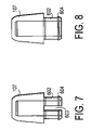
FIG. 8 is another side view of the cap top of FIG. 7.
DETAILED DESCRIPTION OF THE INVENTION
As described herein, multiple embodiments of a screwdriver are provided. In one embodiment, a screwdriver having interchangeable bit bodies with permanently affixed bit heads is provided. In another embodiment, at least one transparent end cap is provided that displays a bit head in an engaged position ready for use. In another alternative, transparent end caps are provided at two ends of the screwdriver. In still another embodiment, two end caps are provided that may nest with each other. In yet another embodiment, a rotatable end cap is provided. It will be recognized that these various embodiments of a precision screwdriver may be utilized independently or in combination with one or more of the other embodiments. For ease of description, a screwdriver utilizing each of these embodiments in one combination is shown herein with regard to the figures presented. However, this combination is shown for illustrative purposes and a user's preferred embodiment may comprise only one or some subset of a combination of the embodiments and concepts described herein.
FIG. 1 shows an exploded side view of one embodiment of a screwdriver 100 having a main body 101 that holds at least two bit bodies 102 and 103, each having at least two bit heads 102A, 102B, 103A and 103B. As shown, the main body 101 may be cylindrically shaped, however, other shapes may be utilized while still advantageously utilizing the various embodiments of the concepts provided herein. It is understood that the main body may hold only one bit body or a main body may hold two or more bit bodies. Bit heads 102A, 102B, 103A and 103B are permanently affixed to the bit bodies 102 and 103 and can be a large Phillips head 103A, a large flat head 103B, a small Phillips head 102A, and a small flat head 102B. Other bits however, may be utilized and alternatively the bits may be detachably affixed to the bit bodies. In FIG. 1, large bit heads 103A and 103B are shown on opposite ends of one bit body 103, while small bit heads 102A and 102B are shown at opposite ends of another bit body 102. It is understood that one bit body could alternatively comprise a small head on one end and a large head at the other end, for example.
The bit bodies 102 and 103 shown in FIG. 1 are configured to be quickly and easily removed and inserted into the main body 101 for exposing a desired bit head size and shape for a particular purpose without having to fumble with removing and inserting individual bit heads into apparatus. Permanently affixed bit heads 102A, 102B, 103A and 103B also alleviate risk of losing individual bit heads 102A, 102B, 103A and 103B. The main body can comprise internal grooves, channels or other similar mechanisms for holding a bit body 102 and 103 into place so that rotation of the main body 101 also results in rotation of the bit body and the exposed bit head.
FIG. 1 shows rotatable nesting end caps 104 and 106 that provide caps to cover the bit heads while also allowing rotation between the main body 101 and at least a portion of the end caps 104 and 106 during use. Each end cap 104 and 106 may nest with the opposing end cap as shown in described in more detail with regard to FIGS. 3–5. Each end cap 104 and 106 has a rotational cap top 105 and 107 and a cap body 104A and 106A. The cap body 104A or 106A rotates about the cap top 105 or 107 during use, which allows a user to apply pressure and stabilize the screwdriver 100 at the cap top 105 or 107 respectively while rotating the main body 101. Further, a first end cap 104 can attach to a second end cap 106 allowing the same rotation of the screwdriver 100 while the cap top 105 remains stationary during use (or vice-versa), as shown in more detail in FIG. 4. While FIG. 1 shows the cap tops 105 and 107 separated from the cap bodies 104A and 106A (respectively) in the exploded view of the screwdriver 100, it is understood that in an exemplary embodiment, the nesting cap top may be permanently rotatably affixed to the cap body. Detents 110 provide a mechanism to allow the end caps 104 and 106 to be snapped in place so that the end caps are prevented from easily falling off the screwdriver. As shown in FIG. 6, each end cap may have a corresponding structure 606 that engages the detent 110 when the cap is placed on the main body of the screwdriver.
FIG. 2 shows an exemplary embodiment of a screwdriver 200 with transparent cap tops 105 and 107 displaying bit heads 102A and 103A, thus allowing a user to determine which end of the screwdriver 200 is appropriate for a particular use without having to remove end caps 104 and 106. The bit heads 102A and 103A displayed through the transparent cap tops 105 and 107 are in an engaged position and ready to use. In FIG. 2, exposed bit heads 102A and 103A are a small Phillips head 102A and a large Phillips head 103A. A user familiar with the bit bodies would know from looking through the transparent cap tops 105 and 107 which end of the screwdriver contained large bit heads 103A and 103B and which end housed a bit body having small bit heads 102A and 102B, so that if the user needed a small flat head, for example, the user would remove the end cap 104 covering the small Phillips bit head 102A, remove the bit body from the main body 101, rotate the bit body and insert it into the main body 101 so that the small flat head would be the exposed bit head. In this manner, a user may more directly and easily locate the bit desirable for a particular use.
FIG. 3 shows an embodiment of a screwdriver 300 with a removable nesting end cap 106 temporarily attached to another nesting end cap 104. As shown, the end caps are formed so that one end cap may slide over or nest with the other end cap. In an exemplary embodiment shown, the cap bodies are tapered in a manner that allows nesting. In a nesting use, a first end cap is slide over the second end cap until the cap body of the first end cap firmly engages the cap body of the second end cap. Thus an end cap 104 or 106 can be removed and attached to the other end of the screwdriver 300 in a similar fashion to a ball point pen cap attaching to the end of a ball point pen. Further in the example of FIG. 3, the nesting end caps 104 and 106 are each interchangeable and each may be removed from one end of the screwdriver and attached to an opposite end of the screwdriver. As is described below in more detail, the cap tops of the end caps are rotatable. In the example shown in FIG. 3, the cap bodies of two nested end caps engage each other in a manner that still allows for rotation of the screwdriver with respect to the “top” end cap. Thus, as shown in FIG. 3 the main body 101, cap body 104A and cap body 106A may each be relatively unitarily connected and move together with relation to cap top 107 of end cap 106. In this embodiment, of the nesting caps 104 and 106 engage sufficiently into place when attached to one another so that rotation only occurs at the point between the fully exposed cap top 107 and cap body 106A. As shown in FIG. 3, the main body 101 holds a bit body with permanently affixed bit head 103A now exposed and ready for use while conveniently holding the end cap 106 in a nested arrangement. A large Phillips head is shown in FIG. 3, however the bit body can be removed from the main body 101 and inserted in an opposite direction exposing an alternate bit head, i.e. a large flat bit head, while the end cap 106 remains secured in the nested position.
FIG. 4 shows a screwdriver in use 400, where a hand 401 holds and rotates the screwdriver. For illustrative purposes FIG. 4 shows the rotation of a screwdriver while end caps are nested, however, as will be recognized the rotational movement described below is also provided when end caps are not nested and the rotational concepts described herein may be utilized independently of the nesting of two end caps. As shown, the cap top 107 is configured to allow rotation of the screwdriver 400 while the cap top 107 is stationary. Rotation occurs at a connection of the cap top 107 and cap body 106A (a similar rotation point between cap top 105 and cap body 104A is provided for use when the end caps are nested in an opposite manner or when the caps are not nested).
An index finger 402 applies pressure to a cap top 107 and stabilizes the screwdriver while a thumb 403 or thumb and middle finger (not shown) rotates the screwdriver at the main body 101. It is understood that a user can alternatively apply pressure to the cap top 107 with a palm of a second hand while rotating the main body with the thumb 403 and index finger 402 of the first hand 401, or any other similar technique that is most comfortable and effective for the user. The end cap 106 in FIG. 4 was removed from its previous position over the bit body 103 and bit head 103A and attached to the opposite end of the screwdriver in engagement with the cap body 104A. While attaching the end cap 106 to another end cap 104 is an anticipated technique, it is understood that a removed end cap 106 need not be attached to the screwdriver for it to function as intended while providing rotation. The removed end cap 106 can simply be placed to the side and the rotational aspect of end cap 104 may be utilized while the screwdriver 400 is in use.
FIG. 5 shows a cross section of a screwdriver 500 as shown in FIG. 3, with a first nesting cap 106 attached to a second nesting cap 104. Bit bodies 102 and 103 are shown housed in a main body 101. The bit bodies 102 and 103 have permanently affixed exposed bit heads 102A and 103A, as well as permanently affixed bit heads on opposite ends of the bit bodies 102 and 103 contained within the main body 101. While only two bit bodies 102 and 103 are shown, it is understood that the main body 101 could be configured to hold more or less than two bit bodies. The ends of the main body 101 are configured to securely engage bit bodies 102 and 103 as shown. It is desirable that the bit bodies be engaged sufficiently tight such that rotation of the main body 101 also rotates the bit bodies 102 and 103 yet still allowing for the bit bodies to be slide out to switch which bit is being utilized. In one embodiment, the bit bodies and the main body may be shaped to securely engage each other, such as for example through the use of hexagon shaped bit bodies and a hexagon shaped cavity within the main body.
FIG. 6 shows a cross section 600 of a screwdriver end cap 106 having a cap top 107 rotatably connected to a cap body 106A. The rotatable connection of cap top 107 may further be understood with regard to FIGS. 7–8 which illustrate a side view of a cap top.
The cap top 107 comprises apertures 603 in a connecting portion 602 that allows for compression such that the cap top may be inserted into the cap body 106A. The cap top 107 further comprises extension members 604 which extend outward from the connecting portion 602. The cap body 106A comprises a top edge 605 configured to engage to the extension members 604 of cap top 107. Thus, the connecting portion 602 may be compressed during insertion into the cap body 106A. Then when the extension members have been slide past the top edge, the connecting portion may then spring or snap back so that the cap top 107 will now be held in a manner such that the cap top will be engaged with the cap body while still allowing rotation between the cap body and cap top. In this manner the cap top is held in place while still being allowed to freely rotate.
FIG. 7 shows a side view of a cap top 107 illustrating the apertures 603 (on opposing sides of the cap), the connecting portions 602, and the extension members 604. FIG. 8 is a side view of the cap top 107 rotated ninety degrees with respect to the cross section of FIG. 7 illustrating the connecting portion 602 and the extension members 604. Moreover, it will be recognized that the concepts described herein with regard to a cap top that freely rotates with respect to the cap body may be achieved through any number of structural arrangements and that the structures shown herein are merely exemplary. Thus, with respect to the rotating cap body it is merely desirable that rotation between the cap top and cap body be provided while the particular mechanism utilized to achieve such rotation is merely a design choice. It is noted that in nested arrangements such as shown in FIGS. 3 and 4, the outer cap top (such as cap top 107 of FIGS. 3 and 4) may still freely rotate with respect to its corresponding cap body 106A. Because of the tapered profile of the caps 104 and 106, when in the nested arrangement the outer cap body (cap body 106A in the example shown) securely engages the inner cap body (cap body 104A). Advantageously, when nested the outer cap to 107 is allowed to rotate with respect to the inner cap body 104A. Though achieved through the use of tapered bodies, the concept of utilizing nesting caps with rotation between the outer cap top and the inner cap may be achieved through other structures.
The various screwdriver components described above may be formed of a wide variety of material types, and the concepts described herein may be utilized independent of the materials utilized. In one embodiment, the main body 101 may have an outer exterior of a central region of the main body (such as region 405 shown in FIG. 4) that is utilized as a gripping region made of relatively soft high grip material. For example, the material may be a rubber, elastomeric material, or the like. The bit heads may be formed of a metal and the other components may be injection molded plastic. As mentioned, however, other materials may also be utilized.
Further modifications and alternative embodiments of this invention will be apparent to those skilled in the art in view of this description. It will be recognized, therefore, that the present invention is not limited by these example arrangements. Accordingly, this description is to be construed as illustrative only and is for the purpose of teaching those skilled in the art the manner of carrying out the invention. It is to be understood that the forms of the invention herein shown and described are to be taken as the presently preferred embodiments. Various changes may be made in the implementations and architectures. For example, equivalent elements may be substituted for those illustrated and described herein, and certain features of the invention may be utilized independently of the use of other features, all as would be apparent to one skilled in the art after having the benefit of this description of the invention.

Claims (26)

1. A screwdriver, comprising:
a main body configured to hold a bit body in place;
a first end of the screwdriver having a first end cap, the first end cap having a first end cap first portion and a first end cap second portion;
a second end of the screwdriver being located at an end opposite of the first end, the second end having a second end cap, the second end cap having a second end cap first portion and a second end cap second portion; and
wherein each of the end caps is configured to allow rotation between the first portion of the end cap and the second portion of the end cap wherein one of the first portion of the first end cap and the first portion of the second end cap extend beyond an end of the bit body when the bit body is held in place by the main body.
2. The screwdriver of claim 1, wherein the bit body is removable from the main body.
3. The screwdriver of claim 2, wherein the bit body has a first bit head and a second bit head.
4. The screwdriver of claim 3, wherein at least one of the first and second end caps comprises:
a cap top that forms the first portion; and
a cap body that forms the second portion, wherein rotation between the cap top and cap body is provided.
5. The screwdriver of claim 1, wherein at least some of at least one of the first and second end caps is transparent such that a bit head in an engaged ready to use position is displayed.
6. The screwdriver of claim 1, wherein the first and second end caps may nest.
7. The screwdriver of claim 1, wherein the main body includes at least one region formed of a gripping material.
8. A screwdriver, comprising:
a first removable nesting end cap; and
a second removable nesting end cap, the first and second removable nesting end caps configured to nest with each other;
wherein when the first removable nesting end cap and the second removable nesting end cap are nested, a portion of the outer of the two end caps rotates freely with respect to the inner of the two end caps.
9. The screwdriver of claim 8, wherein both of the nesting caps comprises a nesting cap body and a nesting cap top.
10. The screwdriver of claim 9, wherein at least one of the nesting end caps allows rotation with respect to the main body while the one nesting end cap is nested with the other nesting cap.
11. The screwdriver of claim 10, wherein at least some of at least one of the nesting end caps is transparent.
12. The screwdriver of claim 11, wherein the nesting cap top of both the first and second nesting caps is transparent.
13. A screwdriver, comprising:
a main body configured to hold at least two bit heads, a first bit head at a first end of the screwdriver and second bit head at a second end of the screwdriver;
a first end cap covering the first bit head; and
a second end cap covering the second bit head,
wherein the first and second end caps are each configured to allow rotation between a first portion of the end cap and a second portion of the end cap.
14. The screwdriver of claim 13, wherein first and second end caps are nesting end caps.
15. The screwdriver of claim 14, wherein the first portion of the end caps is a cap body, the cap body of the first end cap and the cap body of the second end cap each being configure to engage each other when in a nested position.
16. The screwdriver of claim 15, wherein at least one of the first and second end caps allows rotation even while attached in a nesting manner to the other end cap.
17. The screwdriver of claim 13, wherein at least a portion of at least one of the first and second end caps has is transparent.
18. The screwdriver of claim 17, wherein the second portion of first end cap is a transparent first cap top and the second portion of the second end cap is a transparent second cap top.
19. The screwdriver of claim 18, wherein the main body includes at least one region formed of a gripping material.
20. A screwdriver, comprising:
a main body configured to hold a first bit head and a second bit head, the first and second bit heads being in an engaged position ready for use, the first bit head being at a first end of the screwdriver and the second bit head being at a second end of the screwdriver;
a first transparent cap for exposing at least a portion of the first bit head while covering the first bit head while the first bit head is in the engaged position ready for use; and
a second transparent cap for exposing at least a portion of the second bit head covering the second bit head while the second bit head is in the engaged position ready for use,
wherein the first transparent cap has a first transparent cap top and the second transparent cap has a second transparent cap top, and
wherein the first transparent cap further comprises a non-transparent first cap body and the second transparent cap further comprises a non-transparent second cap body.
21. A screwdriver, comprising:
a main body configured to hold a first bit head and a second bit head, the first and second bit heads being in an engaged position ready for use, the first bit head being at a first end of the screwdriver and the second bit head being at a second end of the screwdriver;
a first transparent cap for exposing at least a portion of the first bit head while covering the first bit head while the first bit head is in the engaged position ready for use; and
a second transparent cap for exposing at least a portion of the second bit head covering the second bit head while the second bit head is in the engaged position ready for use,
wherein the first transparent cap has a first transparent cap top and the second transparent cap has a second transparent cap top, and
wherein the first transparent cap top is rotatable with respect to another portion of the first transparent cap and the second transparent cap top is rotatable with respect to another portion of the second transparent cap.
22. A screwdriver, comprising:
a main body configured to hold a first bit head and a second bit head, the first and second bit heads being in an engaged position ready for use, the first bit head being at a first end of the screwdriver and the second bit head being at a second end of the screwdriver;
a first transparent cap for exposing at least a portion of the first bit head while covering the first bit head while the first bit head is in the engaged position ready for use; and
a second transparent cap for exposing at least a portion of the second bit head covering the second bit head while the second bit head is in the engaged position ready for use,
wherein at least a portion of at least one of the first transparent cap and the second transparent cap is non-transparent.
23. A screwdriver, comprising:
a main body configured to hold a first bit head and a second bit head, the first and second bit heads being in an engaged position ready for use, the first bit head being at a first end of the screwdriver and the second bit head being at a second end of the screwdriver;
a first transparent cap for exposing at least a portion of the first bit head while covering the first bit head while the first bit head is in the engaged position ready for use; and
a second transparent cap for exposing at least a portion of the second bit head covering the second bit head while the second bit head is in the engaged position ready for use,
wherein the first and second transparent caps may nest.
24. A screwdriver, comprising:
a main body configured to hold a first bit head and a second bit head, the first and second bit heads being in an engaged position ready for use, the first bit head being at a first end of the screwdriver and the second bit head being at a second end of the screwdriver;
a first transparent cap for exposing at least a portion of the first bit head while covering the first bit head while the first bit head is in the engaged position ready for use;
a second transparent cap for exposing at least a portion of the second bit head covering the second bit head while the second bit head is in the engaged position ready for use; and
a first bit body and a second bit body, the first bit head being attached to the first bit body and the second bit head being attached to the second bit body.
25. The screwdriver of claim 24, further comprising a third bit head attached to the first bit body and a fourth bit head attached to the second bit body.
26. A screwdriver, comprising:
a main body configured to hold a first bit head and a second bit head, the first and second bit heads being in an engaged position ready for use, the first bit head being at a first end of the screwdriver and the second bit head being at a second end of the screwdriver;
a first transparent cap for exposing at least a portion of the first bit head while covering the first bit head while the first bit head is in the engaged position ready for use; and
a second transparent cap for exposing at least a portion of the second bit head covering the second bit head while the second bit head is in the engaged position ready for use,
wherein the main body includes at least one region formed of a gripping material.
US11/436,105 2006-05-17 2006-05-17 Multi-bit precision screwdriver Active US7255028B1 (en)

Priority Applications (1)

Application Number Priority Date Filing Date Title
US11/436,105 US7255028B1 (en) 2006-05-17 2006-05-17 Multi-bit precision screwdriver

Applications Claiming Priority (1)

Application Number Priority Date Filing Date Title
US11/436,105 US7255028B1 (en) 2006-05-17 2006-05-17 Multi-bit precision screwdriver

Publications (1)

Publication Number Publication Date
US7255028B1 true US7255028B1 (en) 2007-08-14

Family

ID=38336925

Family Applications (1)

Application Number Title Priority Date Filing Date
US11/436,105 Active US7255028B1 (en) 2006-05-17 2006-05-17 Multi-bit precision screwdriver

Country Status (1)

Country Link
US (1) US7255028B1 (en)

Cited By (13)

* Cited by examiner, † Cited by third party
Publication number Priority date Publication date Assignee Title
US20080196559A1 (en) * 2007-02-20 2008-08-21 Team Fair Holdings Limited Multi purpose driving tool
EP2116336A1 (en) * 2008-05-08 2009-11-11 Centro Style S.p.A. Tool for precision works
US20110146464A1 (en) * 2009-12-22 2011-06-23 Hung-Ming Hu Clamping member for portable and replaceable bit assembly
US20120111582A1 (en) * 2010-10-18 2012-05-10 John Elliot Bahret Integrated stud insertion and removal apparatus
US8621961B2 (en) 2009-04-28 2014-01-07 Milwaukee Electric Tool Corporation Multi-purpose tool
US20150143681A1 (en) * 2013-11-22 2015-05-28 Ford Global Technologies, Llc Driveshaft removal tool with angled tip
USD754513S1 (en) 2010-02-05 2016-04-26 Milwaukee Electric Tool Corporation Screwdriver head
US20180316151A1 (en) * 2014-07-22 2018-11-01 Milwaukee Electric Tool Corporation Hand tools
USD887243S1 (en) * 2018-11-13 2020-06-16 Hong Ann Tool Industries Co., Ltd. Screwdriver
USD927625S1 (en) * 2019-10-17 2021-08-10 Fuxiang Liu Golf knife
USD931397S1 (en) * 2019-10-17 2021-09-21 Fuxiang Liu Golf knife
US20210387320A1 (en) * 2020-06-12 2021-12-16 Richard J. Macor Pocket screwdriver
USD976667S1 (en) * 2021-02-01 2023-01-31 Shanghai HOTO Technology Co., Ltd Screwdriver shank

Citations (45)

* Cited by examiner, † Cited by third party
Publication number Priority date Publication date Assignee Title
US686424A (en) * 1901-05-06 1901-11-12 William H Egleton Screw-driver kit.
US1250328A (en) * 1917-02-14 1917-12-18 Edwin L Langford Combination-tool.
US2022775A (en) * 1934-02-27 1935-12-03 Holland-Letz Friedrich Wilhelm Multiple pocket tool
US2196849A (en) * 1937-05-12 1940-04-09 George R Beeg Pocket screw driver and the like
US3114401A (en) * 1961-06-26 1963-12-17 Algot T Johnson Hand tools of the nature of screw drivers, socket wrenches and the like
US3753455A (en) 1971-07-16 1973-08-21 R Butler Selective chamber screwdriver
US4300607A (en) * 1980-03-07 1981-11-17 Mellinger Ralph D Variable length tool handle
US4372362A (en) 1981-02-23 1983-02-08 Ahn Min H Tool
US4463788A (en) 1983-06-09 1984-08-07 Antonio Corona & Associates R & D Ltd. Multiple bit screwdriver
US4572038A (en) 1984-02-08 1986-02-25 Graham Charles H Multi-purpose tool
WO1989003282A1 (en) 1987-10-08 1989-04-20 W. Holland-Letz Gmbh & Co. Kg Pocket screwdriver with bit magazine and clip
US4846042A (en) * 1988-08-11 1989-07-11 Wetty W Les Tool handle with a rotatable cap
US4867326A (en) * 1988-08-25 1989-09-19 Cp Packaging Child resistant cap and tube assembly
US4924733A (en) * 1985-08-16 1990-05-15 Mckenzie Archibald M Multiple bit screwdriver
US4969231A (en) * 1989-05-17 1990-11-13 Easco Hand Tools, Inc. Hand tool handle having end cap with indicia
US5228363A (en) 1989-03-10 1993-07-20 Corona Franco O Hand-held multiple object implement
US5337637A (en) 1993-07-14 1994-08-16 Bih Lien Chen L Screwdriver with replaceable driver bits
US5442982A (en) 1993-11-26 1995-08-22 Bell; Dennis J. Nesting pocket screwdrivers
US5526724A (en) * 1993-08-10 1996-06-18 Bruggeman; Homer F. Screw driver with palm knob
US5566596A (en) 1995-09-26 1996-10-22 Lin; Ching-Chou Hand tool assembly
US5613413A (en) 1996-02-20 1997-03-25 Huang; Chiu-Hua Handle of a hand tool
US5673600A (en) 1995-03-29 1997-10-07 Nec Corporation Screwdriver having plural kinds of driver pins
US5823078A (en) 1997-01-15 1998-10-20 Liu; Tsai-Fa Precision screwdriver equipped with a rotatable cap
US5868048A (en) 1997-04-25 1999-02-09 Cassutti; Paolo Adjustment hand tool/screwdriver
US5904080A (en) * 1996-03-22 1999-05-18 Anderson; Wayne 8 in 1 tool bit driver hand tool
US5924339A (en) * 1998-03-03 1999-07-20 Huang; Chin-Tan Screwdriver
US6186036B1 (en) 1999-08-18 2001-02-13 Yung Hsu Huang Tool combination
US6237451B1 (en) 2000-03-27 2001-05-29 Yong Lung Wei Tool box
US6332384B1 (en) 2001-02-09 2001-12-25 Gary Paul Cluthe Multiple bit screwdriver
US6354177B2 (en) 2000-02-29 2002-03-12 Black & Decker Inc. 6-in-1 rotary tool
US6374711B2 (en) 1997-10-24 2002-04-23 Wayne Anderson 50-in-1 screwdriver and socket driver
US6502484B2 (en) 2001-01-22 2003-01-07 Lee Pao-Hsi Screwdriver with easily replaceable bits
US6508156B1 (en) 2001-09-24 2003-01-21 Yong Lung Wei Screwdriver tool box structure
US20030029283A1 (en) 2001-08-13 2003-02-13 Ran Yaar Multiple screwdriver
US20030084758A1 (en) 2001-11-02 2003-05-08 Chiang Mei Hui Rotary screwdriver with hidden and replaceable screwdriver bits
US6601483B2 (en) 2001-04-19 2003-08-05 Futureworks Concepts Ltd. Automatic bit changing screwdriver
US6629478B2 (en) 2001-07-31 2003-10-07 Burton Kozak Hand tool device with opposing drive ends and storage for multiple tool bits
US6655243B2 (en) * 1996-07-31 2003-12-02 Wayne Anderson Multiple-in-1 precision hand tool
US20040065178A1 (en) 1996-07-31 2004-04-08 Wayne Anderson Multiple-in-1 precision hand tool
US20040123705A1 (en) * 2002-12-26 2004-07-01 Emerson Electric Co. Screwdriver Handle with Rotatable End Cap
US20040129119A1 (en) 2003-01-03 2004-07-08 Clarke Gary Richard Multiple purpose tool
US20040139832A1 (en) 2002-08-09 2004-07-22 Hu Cheng-Tsan Precision screwdriver having a turning head
US6923099B2 (en) 2002-07-17 2005-08-02 Julie Rugg Scrapbooking instrument set
US20050204878A1 (en) 2004-03-18 2005-09-22 Hu Cheng-Tsan Screwdriver heads chamber for a precise screwdriver
US7052128B1 (en) * 2005-03-30 2006-05-30 Su Kung-Ping Pen-shaped spectacles repair kit

Patent Citations (46)

* Cited by examiner, † Cited by third party
Publication number Priority date Publication date Assignee Title
US686424A (en) * 1901-05-06 1901-11-12 William H Egleton Screw-driver kit.
US1250328A (en) * 1917-02-14 1917-12-18 Edwin L Langford Combination-tool.
US2022775A (en) * 1934-02-27 1935-12-03 Holland-Letz Friedrich Wilhelm Multiple pocket tool
US2196849A (en) * 1937-05-12 1940-04-09 George R Beeg Pocket screw driver and the like
US3114401A (en) * 1961-06-26 1963-12-17 Algot T Johnson Hand tools of the nature of screw drivers, socket wrenches and the like
US3753455A (en) 1971-07-16 1973-08-21 R Butler Selective chamber screwdriver
US4300607A (en) * 1980-03-07 1981-11-17 Mellinger Ralph D Variable length tool handle
US4372362A (en) 1981-02-23 1983-02-08 Ahn Min H Tool
US4463788A (en) 1983-06-09 1984-08-07 Antonio Corona & Associates R & D Ltd. Multiple bit screwdriver
US4572038A (en) 1984-02-08 1986-02-25 Graham Charles H Multi-purpose tool
US4924733A (en) * 1985-08-16 1990-05-15 Mckenzie Archibald M Multiple bit screwdriver
WO1989003282A1 (en) 1987-10-08 1989-04-20 W. Holland-Letz Gmbh & Co. Kg Pocket screwdriver with bit magazine and clip
US4846042A (en) * 1988-08-11 1989-07-11 Wetty W Les Tool handle with a rotatable cap
US4867326A (en) * 1988-08-25 1989-09-19 Cp Packaging Child resistant cap and tube assembly
US5228363A (en) 1989-03-10 1993-07-20 Corona Franco O Hand-held multiple object implement
US4969231A (en) * 1989-05-17 1990-11-13 Easco Hand Tools, Inc. Hand tool handle having end cap with indicia
US5337637A (en) 1993-07-14 1994-08-16 Bih Lien Chen L Screwdriver with replaceable driver bits
US5526724A (en) * 1993-08-10 1996-06-18 Bruggeman; Homer F. Screw driver with palm knob
US5442982A (en) 1993-11-26 1995-08-22 Bell; Dennis J. Nesting pocket screwdrivers
US5673600A (en) 1995-03-29 1997-10-07 Nec Corporation Screwdriver having plural kinds of driver pins
US5566596A (en) 1995-09-26 1996-10-22 Lin; Ching-Chou Hand tool assembly
US5613413A (en) 1996-02-20 1997-03-25 Huang; Chiu-Hua Handle of a hand tool
US5904080A (en) * 1996-03-22 1999-05-18 Anderson; Wayne 8 in 1 tool bit driver hand tool
US6655243B2 (en) * 1996-07-31 2003-12-02 Wayne Anderson Multiple-in-1 precision hand tool
US20040065178A1 (en) 1996-07-31 2004-04-08 Wayne Anderson Multiple-in-1 precision hand tool
US5823078A (en) 1997-01-15 1998-10-20 Liu; Tsai-Fa Precision screwdriver equipped with a rotatable cap
US6050158A (en) 1997-04-25 2000-04-18 Cassutti; Paolo Adjustment hand tool/screwdriver
US5868048A (en) 1997-04-25 1999-02-09 Cassutti; Paolo Adjustment hand tool/screwdriver
US6374711B2 (en) 1997-10-24 2002-04-23 Wayne Anderson 50-in-1 screwdriver and socket driver
US5924339A (en) * 1998-03-03 1999-07-20 Huang; Chin-Tan Screwdriver
US6186036B1 (en) 1999-08-18 2001-02-13 Yung Hsu Huang Tool combination
US6354177B2 (en) 2000-02-29 2002-03-12 Black & Decker Inc. 6-in-1 rotary tool
US6237451B1 (en) 2000-03-27 2001-05-29 Yong Lung Wei Tool box
US6502484B2 (en) 2001-01-22 2003-01-07 Lee Pao-Hsi Screwdriver with easily replaceable bits
US6332384B1 (en) 2001-02-09 2001-12-25 Gary Paul Cluthe Multiple bit screwdriver
US6601483B2 (en) 2001-04-19 2003-08-05 Futureworks Concepts Ltd. Automatic bit changing screwdriver
US6629478B2 (en) 2001-07-31 2003-10-07 Burton Kozak Hand tool device with opposing drive ends and storage for multiple tool bits
US20030029283A1 (en) 2001-08-13 2003-02-13 Ran Yaar Multiple screwdriver
US6508156B1 (en) 2001-09-24 2003-01-21 Yong Lung Wei Screwdriver tool box structure
US20030084758A1 (en) 2001-11-02 2003-05-08 Chiang Mei Hui Rotary screwdriver with hidden and replaceable screwdriver bits
US6923099B2 (en) 2002-07-17 2005-08-02 Julie Rugg Scrapbooking instrument set
US20040139832A1 (en) 2002-08-09 2004-07-22 Hu Cheng-Tsan Precision screwdriver having a turning head
US20040123705A1 (en) * 2002-12-26 2004-07-01 Emerson Electric Co. Screwdriver Handle with Rotatable End Cap
US20040129119A1 (en) 2003-01-03 2004-07-08 Clarke Gary Richard Multiple purpose tool
US20050204878A1 (en) 2004-03-18 2005-09-22 Hu Cheng-Tsan Screwdriver heads chamber for a precise screwdriver
US7052128B1 (en) * 2005-03-30 2006-05-30 Su Kung-Ping Pen-shaped spectacles repair kit

Cited By (18)

* Cited by examiner, † Cited by third party
Publication number Priority date Publication date Assignee Title
WO2008101335A1 (en) * 2007-02-20 2008-08-28 Team Fair Holdings Limited Multi purpose driving tool
US20080196559A1 (en) * 2007-02-20 2008-08-21 Team Fair Holdings Limited Multi purpose driving tool
EP2116336A1 (en) * 2008-05-08 2009-11-11 Centro Style S.p.A. Tool for precision works
US8621961B2 (en) 2009-04-28 2014-01-07 Milwaukee Electric Tool Corporation Multi-purpose tool
US20110146464A1 (en) * 2009-12-22 2011-06-23 Hung-Ming Hu Clamping member for portable and replaceable bit assembly
USD754513S1 (en) 2010-02-05 2016-04-26 Milwaukee Electric Tool Corporation Screwdriver head
US20120111582A1 (en) * 2010-10-18 2012-05-10 John Elliot Bahret Integrated stud insertion and removal apparatus
US8807232B2 (en) * 2010-10-18 2014-08-19 John Elliot Bahret Integrated stud insertion and removal apparatus
US20150143681A1 (en) * 2013-11-22 2015-05-28 Ford Global Technologies, Llc Driveshaft removal tool with angled tip
US9339921B2 (en) * 2013-11-22 2016-05-17 Ford Global Technologies, Llc Driveshaft removal tool with angled tip
US20180316151A1 (en) * 2014-07-22 2018-11-01 Milwaukee Electric Tool Corporation Hand tools
US11211758B2 (en) * 2014-07-22 2021-12-28 Milwaukee Electric Tool Corporation Hand tools
USD887243S1 (en) * 2018-11-13 2020-06-16 Hong Ann Tool Industries Co., Ltd. Screwdriver
USD927625S1 (en) * 2019-10-17 2021-08-10 Fuxiang Liu Golf knife
USD931397S1 (en) * 2019-10-17 2021-09-21 Fuxiang Liu Golf knife
US20210387320A1 (en) * 2020-06-12 2021-12-16 Richard J. Macor Pocket screwdriver
US11518020B2 (en) * 2020-06-12 2022-12-06 Proprietary Technologies, Inc. Pocket screwdriver
USD976667S1 (en) * 2021-02-01 2023-01-31 Shanghai HOTO Technology Co., Ltd Screwdriver shank

Similar Documents

Publication Publication Date Title
US7255028B1 (en) Multi-bit precision screwdriver
US4848197A (en) Multiple bit handtool
US6095470A (en) Ejecting electronic instrument mount
US5062173A (en) Multifunction tool
US6327942B1 (en) Multiple bit driver
US9314909B2 (en) Dismantleable tubular gripping element
US9975234B2 (en) Pocket hand tool
KR100687545B1 (en) Writing device having variable grip
US5174178A (en) Selective tool handle
US20150082950A1 (en) Radial foldout tool
US8926203B1 (en) Writing instrument gripping aid and writing instrument having the same
US20060186007A1 (en) Tool accessory case index
US20100192733A1 (en) Handle with Asymmetrical Configuration
US20080035511A1 (en) Tool box for storing a tool handle and multiple tool tips
WO2006102737A1 (en) Multi-bit, dual-mode screwdriver for either manual or powered actuation
US7249543B1 (en) 4-in-1 pocket screwdriver
WO2004024465A1 (en) Grip for hand held instruments
US7287451B2 (en) Multiple bit screwdriver
US20070289418A1 (en) Multiple bit screwdriver
US10730176B2 (en) Hand tool
JP5022260B2 (en) Writing instrument
US6997088B2 (en) Screwdriver heads chamber for a precise screwdriver
JP6383528B2 (en) Writing instrument that is easy to assemble
JP3160448U (en) Two-color ballpoint pen
CA2499790A1 (en) Multiple bit screwdriver

Legal Events

Date Code Title Description
AS Assignment

Owner name: HELEN OF TROY LIMITED, BARBADOS

Free format text: ASSIGNMENT OF ASSIGNORS INTEREST;ASSIGNORS:DI BITONTO, ANTHONY;LJUNGGREN, ANTON;KATZ, PAUL;AND OTHERS;REEL/FRAME:018000/0879;SIGNING DATES FROM 20060605 TO 20060612

STCF Information on status: patent grant

Free format text: PATENTED CASE

FPAY Fee payment

Year of fee payment: 4

FPAY Fee payment

Year of fee payment: 8

MAFP Maintenance fee payment

Free format text: PAYMENT OF MAINTENANCE FEE, 12TH YEAR, LARGE ENTITY (ORIGINAL EVENT CODE: M1553); ENTITY STATUS OF PATENT OWNER: LARGE ENTITY

Year of fee payment: 12