US7240894B2 - Pulse width modulated solenoid - Google Patents
Pulse width modulated solenoid Download PDFInfo
- Publication number
- US7240894B2 US7240894B2 US10/823,466 US82346604A US7240894B2 US 7240894 B2 US7240894 B2 US 7240894B2 US 82346604 A US82346604 A US 82346604A US 7240894 B2 US7240894 B2 US 7240894B2
- Authority
- US
- United States
- Prior art keywords
- valve
- invention according
- passage
- fluid control
- control body
- Prior art date
- Legal status (The legal status is an assumption and is not a legal conclusion. Google has not performed a legal analysis and makes no representation as to the accuracy of the status listed.)
- Expired - Fee Related, expires
Links
Images


Classifications
-
- F—MECHANICAL ENGINEERING; LIGHTING; HEATING; WEAPONS; BLASTING
- F16—ENGINEERING ELEMENTS AND UNITS; GENERAL MEASURES FOR PRODUCING AND MAINTAINING EFFECTIVE FUNCTIONING OF MACHINES OR INSTALLATIONS; THERMAL INSULATION IN GENERAL
- F16K—VALVES; TAPS; COCKS; ACTUATING-FLOATS; DEVICES FOR VENTING OR AERATING
- F16K31/00—Actuating devices; Operating means; Releasing devices
- F16K31/02—Actuating devices; Operating means; Releasing devices electric; magnetic
- F16K31/06—Actuating devices; Operating means; Releasing devices electric; magnetic using a magnet, e.g. diaphragm valves, cutting off by means of a liquid
- F16K31/0644—One-way valve
- F16K31/0655—Lift valves
- F16K31/0665—Lift valves with valve member being at least partially ball-shaped
-
- F—MECHANICAL ENGINEERING; LIGHTING; HEATING; WEAPONS; BLASTING
- F16—ENGINEERING ELEMENTS AND UNITS; GENERAL MEASURES FOR PRODUCING AND MAINTAINING EFFECTIVE FUNCTIONING OF MACHINES OR INSTALLATIONS; THERMAL INSULATION IN GENERAL
- F16K—VALVES; TAPS; COCKS; ACTUATING-FLOATS; DEVICES FOR VENTING OR AERATING
- F16K31/00—Actuating devices; Operating means; Releasing devices
- F16K31/02—Actuating devices; Operating means; Releasing devices electric; magnetic
- F16K31/06—Actuating devices; Operating means; Releasing devices electric; magnetic using a magnet, e.g. diaphragm valves, cutting off by means of a liquid
- F16K31/0644—One-way valve
- F16K31/0668—Sliding valves
Definitions
- the present invention generally relates to solenoid control valves, and more particularly to a pulse width modulated solenoid control valve for controlling hydraulic functions of a transmission for a vehicle.
- automatic transmission control systems generally employ solenoids in order to control the pressure and flow of the transmission fluid.
- the control of transmission fluid pressure can be used to engage and disengage a transmission clutch in response to an electrical input signal supplied to the solenoid, or the control of transmission fluid pressure can be used to maintain transmission line pressure.
- solenoids employ a solenoid control valve to aid in the regulation of the fluid flow by the solenoid.
- An example of a solenoid control valve can be found in U.S. Pat. No. 4,998,559 to McAuliffe et al., the entire specification of which is incorporated herein by reference. Recently, the use of pulse width modulated solenoids has become more prevalent in certain automotive applications.
- pulse width modulated conventional solenoid control valves have been somewhat successful in meeting the demands of the automotive industry, these pulse width modulated solenoid control valves can be further improved upon, e.g., in the areas of cost, quality, performance, and the like.
- a new and improved solenoid control valve is provided, in accordance with the general teachings of the present invention. More specifically, a new and improved pulse width modulated solenoid control valve is provided, in accordance with one embodiment of the present invention
- the solenoid control valve preferably employs a plastic control valve body that preferably includes a segmented flow path that adds strength to the supply tube portion.
- a stepped coil portion is preferably provided.
- an actuation rod is preferably provided that is tapered adjacent to and contacting the armature so as to reduce flux shorting and improve operating characteristics. Accordingly, the solenoid control valve of the present invention preferably provides a characteristic performance curve.
- a solenoid fluid control valve comprising: (1) a fluid control body adapted for being received in a fluid housing, said fluid control body including a central cavity, and having a pressure supply passage at a first end and a radially extending pressure control passage; (2) a feed supply tube positioned in said central cavity, said feed supply tube including an outer diameter in communication with the pressure control passage, and including an inner bore operably connected to said pressure supply passage, said feed supply tube being supported in said central cavity of said fluid control body by way of a radially and axially extending wall, said wall being segmented into a plurality of longitudinally extending flow chambers, said feed supply tube including a valve receiving chamber area; (3) a valve seat portion being made of a metallic material and press fit into said fluid control body, said valve seat portion including a valve seat and a passage in communication between said valve seat and said pressure control passage; (4) a valve contained in said valve receiving chamber operable to selectively close off communication between said pressure supply passage
- a solenoid fluid control valve comprising: (1) a fluid control body adapted for being received in a fluid housing, said fluid control body including a central cavity, and having a pressure supply passage at a first end and a radially extending pressure control passage; (2) a feed supply tube positioned in said central cavity, said feed supply tube including an outer diameter in communication with the pressure control passage, and including an inner bore operably connected to said pressure supply passage, said feed supply tube being supported in said central cavity of said fluid control body by way of a radially and axially extending wall, said wall being segmented into a plurality of longitudinally extending flow chambers, said feed supply tube including a valve receiving chamber area; (3) a valve seat portion being made of a metallic material and press fit into said fluid control body, said valve seat portion including a valve seat and a passage in communication between said valve seat and said pressure control passage; (4) a valve contained in said valve receiving chamber operable to selectively close off communication between said pressure supply passage
- a solenoid fluid control valve comprising: (1) a fluid control body adapted for being received in a fluid housing, said fluid control body including a central cavity, and having a pressure supply passage at a first end and a radially extending pressure control passage; (2) a feed supply tube positioned in said central cavity, said feed supply tube including an outer diameter in communication with the pressure control passage, and including an inner bore operably connected to said pressure supply passage, said feed supply tube being supported in said central cavity of said fluid control body by way of a radially and axially extending wall, said wall being segmented into a plurality of longitudinally extending flow chambers, said feed supply tube including a valve receiving chamber area; (3) a valve seat portion being made of a metallic material and press fit into said fluid control body, said valve seat portion including a valve seat and a passage in communication between said valve seat and said pressure control passage; (4) a valve contained in said valve receiving chamber operable to selectively close off communication between said pressure supply passage
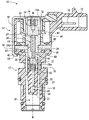
- FIG. 1 is a cross-sectional view of the solenoid control valve of the present invention
- FIG. 2 is a side view of the control valve body of the present invention
- FIG. 3 is a top view of the control valve body of the present invention.
- FIG. 4 is a sectional view taken along line 4 — 4 of FIG. 2 ;
- FIG. 5 is a sectional view taken along line 5 — 5 of FIG. 2 ;
- FIG. 6 is a sectional view taken along line 6 — 6 of FIG. 2 ;
- FIG. 7 is a sectional view taken along line 7 — 7 of FIG. 2 ;
- FIG. 8 is a second partially broken away sectional view of the valve body of the present invention.
- FIG. 9 is a performance curve of the operational characteristics of the present invention when operating at 40 psi;
- FIG. 10 is a performance curve of the operational characteristics of the present invention when operating at 120 psi.
- FIG. 11 is a performance curve of the operational characteristics of the present invention when operating at 215 psi.
- the solenoid control valve includes a fluid control body generally indicated at 12 , and a solenoid portion generally indicated at 14 .
- the fluid control body 12 is preferably adapted for being received in a fluid manifold housing in a valve body of a transmission.
- the fluid control body 12 preferably includes a central cavity 16 , wherein the central cavity 16 preferably includes a fluid supply passage 18 and a fluid control passage 20 . These passages preferably communicate with either a supply line in the manifold or a control line, as is readily known in the art.
- a feed supply tube 22 is preferably integrally molded with the fluid control body 12 .
- Feed supply tube 22 preferably includes an outer diameter 24 .
- the outer diameter 24 is in communication with the control passage 20
- the feed supply tube 21 preferably includes an inner bore 26 in communication with the supply passage 18 through laterally extending port 28 .
- the feed supply tube 22 is preferably supported in the cavity 16 by at least one or more segmented areas 30 , best shown in FIG. 6 . Preferably, there are three segmented flow passages 30 a on each side of the feed supply tube 22 , as shown in FIG. 6 .
- the feed supply tube 22 preferably includes a valve receiving area 32 .
- a valve seat-forming portion 34 is preferably made out of a metal material and is press fit into the feed supply tube 22 .
- the outer diameter of the valve seat-forming portion 34 is preferably press fit into the valve receiving area 32 .
- An alignment shelf 36 is preferably provided on the control body for providing proper depth of alignment of the valve seat member 34 .
- a ball valve 38 is preferably held between the valve seat 40 and the valve retainer portion 32 .
- a return spring 35 preferably biases the ball valve 38 toward valve seat 40 .
- the valve seat member 34 preferably provides a passageway 42 to the control passage 20 .
- the ball valve 38 is preferably operable to selectively cut off supply of flow from the supply channel 18 to the control passage 20 .
- the first step of the path of fluid flow is that fluid enters into the lateral extending support 28 from outside of the solenoid control valve 10 .
- the fluid then flows through the fluid supply passage 18 and into inner bore 26 . Once the fluid enters the inner bore 26 , the fluid will flow through ball valve 38 , through passageway 42 , and into the control passage 20 .
- the solenoid control valve 10 is configured such that the lateral extending support 28 and the control passage 20 only communicate fluid through ball valve 38 .
- the valve seat member 34 is preferably press fit into the flux washer 62 forming a pole piece assembly 64 .
- the flux washer 62 is preferably a stamped member and the valve seat member 34 is preferably a screw turned member. Assembly of these pieces together reduces the cost of the assembly.
- Solenoid portion 14 is preferably secured to the fluid control body 12 .
- An O-ring 44 is preferably disposed between the fluid control body 12 and the pole piece assembly 64 .
- the solenoid 14 preferably includes a central axis A—A and has a coil 46 wound around a nonmagnetic bobbin member 48 .
- the bobbin member 48 is preferably stepped radially, and includes a radially outward wall 52 and, a radially inward wall 54 .
- a one-piece casing member 50 preferably includes a radially extending flux tube forming annular portion 56 .
- the casing 50 also preferably crimpingly attaches the solenoid 14 to the body 12 by way of the crimped portion 58 .
- An armature 60 is preferably provided, which fits within the wall 54 and is axially movable in response to a current in the coil.
- the pole piece assembly 64 is preferably secured between the lower portion of the bobbin 48 and the control body 12 .
- the pole piece assembly 64 preferably includes a center orifice 64 a which allows the valve seat member 34 to be press fit therein.
- the control rod 66 preferably has a tapered upper end 67 and is movable within the valve seat member 34 .
- the armature 60 preferably moves the control rod 66 .
- the tapered pin preferably reduces magnetic flux shorting, thereby improving performance without sacrificing strength.
- Assembly standoffs 69 are preferably provided. These standoffs are preferably axially radially extending rib members. These rib members act to preferably provide precise positioning of the casing 50 in the final solenoid control valve of the present invention.
- a retention groove 76 is preferably provided that is engaged by a clip member (not shown) when securing the control valve 10 in a fluid manifold housing in a valve body of a transmission, for example.
- a clip member not shown
- a preferred embodiment has two ribs 69 ′, 69 ′′, respectively, spaced 180° apart and a wider rib 69 ′′′ positioned 90° between ribs 69 ′, 69 ′′, respectively.
- the coil 46 , bobbin 48 and coil contacts 70 are preferably overmolded to form connector 72 .
- FIGS. 9 through 11 are transfer function progressions showing the duty cycle performance of the pulse width modulation of the solenoid of the present invention when operating with 40, 120 and 215 pounds per square inch of fluid pressure applied at the supply passage. As shown therein, the performance characteristics are optimized in the design of the present invention.
Abstract
A pulse width modulated solenoid control valve is described, wherein the valve includes a polymer fluid control body. The body includes a segmented fluid flow path for providing strength to the fluid control body assembly. Stand off ribs are provided to improve assembly into a control manifold. A casing forms an integral flux tube. A tapered push rod is used to reduce flux shorting.
Description
The instant application claims priority to U.S. Provisional Patent Application Ser. No. 60/474,774, filed May 30, 2003, the entire specification of which is expressly incorporated herein by reference.
The present invention generally relates to solenoid control valves, and more particularly to a pulse width modulated solenoid control valve for controlling hydraulic functions of a transmission for a vehicle.
Various solenoid designs have been used in the automotive industry, including those for use in conjunction with automatic transmission systems. For example, automatic transmission control systems generally employ solenoids in order to control the pressure and flow of the transmission fluid. In this manner, the control of transmission fluid pressure can be used to engage and disengage a transmission clutch in response to an electrical input signal supplied to the solenoid, or the control of transmission fluid pressure can be used to maintain transmission line pressure.
Generally, solenoids employ a solenoid control valve to aid in the regulation of the fluid flow by the solenoid. An example of a solenoid control valve can be found in U.S. Pat. No. 4,998,559 to McAuliffe et al., the entire specification of which is incorporated herein by reference. Recently, the use of pulse width modulated solenoids has become more prevalent in certain automotive applications.
Although pulse width modulated conventional solenoid control valves have been somewhat successful in meeting the demands of the automotive industry, these pulse width modulated solenoid control valves can be further improved upon, e.g., in the areas of cost, quality, performance, and the like.
Accordingly, there exists a need for new and improved pulse width modulated solenoid control valves.
A new and improved solenoid control valve is provided, in accordance with the general teachings of the present invention. More specifically, a new and improved pulse width modulated solenoid control valve is provided, in accordance with one embodiment of the present invention
The solenoid control valve preferably employs a plastic control valve body that preferably includes a segmented flow path that adds strength to the supply tube portion. In accordance with a preferred embodiment of the present invention, a stepped coil portion is preferably provided. In accordance with another preferred embodiment of the present invention, an actuation rod is preferably provided that is tapered adjacent to and contacting the armature so as to reduce flux shorting and improve operating characteristics. Accordingly, the solenoid control valve of the present invention preferably provides a characteristic performance curve.
In accordance with a first embodiment of the present invention, a solenoid fluid control valve is provided, comprising: (1) a fluid control body adapted for being received in a fluid housing, said fluid control body including a central cavity, and having a pressure supply passage at a first end and a radially extending pressure control passage; (2) a feed supply tube positioned in said central cavity, said feed supply tube including an outer diameter in communication with the pressure control passage, and including an inner bore operably connected to said pressure supply passage, said feed supply tube being supported in said central cavity of said fluid control body by way of a radially and axially extending wall, said wall being segmented into a plurality of longitudinally extending flow chambers, said feed supply tube including a valve receiving chamber area; (3) a valve seat portion being made of a metallic material and press fit into said fluid control body, said valve seat portion including a valve seat and a passage in communication between said valve seat and said pressure control passage; (4) a valve contained in said valve receiving chamber operable to selectively close off communication between said pressure supply passage and said pressure control passage; and (5) a solenoid for opening said valve in response to a signal.
In accordance with a second embodiment of the present invention, a solenoid fluid control valve is provided, comprising: (1) a fluid control body adapted for being received in a fluid housing, said fluid control body including a central cavity, and having a pressure supply passage at a first end and a radially extending pressure control passage; (2) a feed supply tube positioned in said central cavity, said feed supply tube including an outer diameter in communication with the pressure control passage, and including an inner bore operably connected to said pressure supply passage, said feed supply tube being supported in said central cavity of said fluid control body by way of a radially and axially extending wall, said wall being segmented into a plurality of longitudinally extending flow chambers, said feed supply tube including a valve receiving chamber area; (3) a valve seat portion being made of a metallic material and press fit into said fluid control body, said valve seat portion including a valve seat and a passage in communication between said valve seat and said pressure control passage; (4) a valve contained in said valve receiving chamber operable to selectively close off communication between said pressure supply passage and said pressure control passage; (5) a solenoid for opening said valve in response to a signal, wherein said solenoid includes a central axis and has a coil wound around a bobbin, spaced from and positioned around said central axis, said coil having radially stepped radial inner diameters; (6) a casing member for attaching said solenoid to said fluid control body; a portion of said casing member extending into the stepped portion of said coil for forming a flux tube therein; and (7) an armature axially movable within said bobbin.
In accordance with a third embodiment of the present invention, a solenoid fluid control valve is provided, comprising: (1) a fluid control body adapted for being received in a fluid housing, said fluid control body including a central cavity, and having a pressure supply passage at a first end and a radially extending pressure control passage; (2) a feed supply tube positioned in said central cavity, said feed supply tube including an outer diameter in communication with the pressure control passage, and including an inner bore operably connected to said pressure supply passage, said feed supply tube being supported in said central cavity of said fluid control body by way of a radially and axially extending wall, said wall being segmented into a plurality of longitudinally extending flow chambers, said feed supply tube including a valve receiving chamber area; (3) a valve seat portion being made of a metallic material and press fit into said fluid control body, said valve seat portion including a valve seat and a passage in communication between said valve seat and said pressure control passage; (4) a valve contained in said valve receiving chamber operable to selectively close off communication between said pressure supply passage and said pressure control passage; (5) a solenoid for opening said valve in response to a signal, wherein said solenoid includes a central axis and has a coil wound around a bobbin, spaced from and positioned around said central axis, said coil having radially stepped radial inner diameters; (6) a casing member for attaching said solenoid to said fluid control body; a portion of said casing member extending into the stepped portion of said coil for forming a flux tube therein; (7) an armature axially movable within said bobbin; (8) a pole piece assembly adjacent said armature and interposed between said bobbin and said fluid control body; and (9) a control rod extending along said central axis and through said pole piece assembly for opening of said valve, said control rod including a tapered end.
Further areas of applicability of the present invention will become apparent from the detailed description provided hereinafter. It should be understood that the detailed description and specific examples, while indicating the preferred embodiment of the invention, are intended for purposes of illustration only and are not intended to limit the scope of the invention.
The present invention will become more fully understood from the detailed description and the accompanying drawings, wherein:
The following description of the preferred embodiment(s) is merely exemplary in nature and is in no way intended to limit the invention, its application, or uses.
Referring to the Figures generally, and FIGS. 1–8 specifically, there is provided a solenoid control valve generally shown at 10, in accordance with the general teachings of the present invention. The solenoid control valve includes a fluid control body generally indicated at 12, and a solenoid portion generally indicated at 14. By way of a non-limiting example, the fluid control body 12 is preferably adapted for being received in a fluid manifold housing in a valve body of a transmission.
The fluid control body 12 preferably includes a central cavity 16, wherein the central cavity 16 preferably includes a fluid supply passage 18 and a fluid control passage 20. These passages preferably communicate with either a supply line in the manifold or a control line, as is readily known in the art. A feed supply tube 22 is preferably integrally molded with the fluid control body 12. Feed supply tube 22 preferably includes an outer diameter 24. The outer diameter 24 is in communication with the control passage 20, and the feed supply tube 21 preferably includes an inner bore 26 in communication with the supply passage 18 through laterally extending port 28. The feed supply tube 22 is preferably supported in the cavity 16 by at least one or more segmented areas 30, best shown in FIG. 6 . Preferably, there are three segmented flow passages 30 a on each side of the feed supply tube 22, as shown in FIG. 6 . The feed supply tube 22 preferably includes a valve receiving area 32.
A valve seat-forming portion 34 is preferably made out of a metal material and is press fit into the feed supply tube 22. The outer diameter of the valve seat-forming portion 34 is preferably press fit into the valve receiving area 32. By this arrangement, fluid passage is allowed to flow axially through the segmented flow passages 30 a , while the webs forming the segmented areas 30 absorb press loads on the valve seat member 34. An alignment shelf 36 is preferably provided on the control body for providing proper depth of alignment of the valve seat member 34. A ball valve 38 is preferably held between the valve seat 40 and the valve retainer portion 32. A return spring 35 preferably biases the ball valve 38 toward valve seat 40. The valve seat member 34 preferably provides a passageway 42 to the control passage 20. The ball valve 38 is preferably operable to selectively cut off supply of flow from the supply channel 18 to the control passage 20. The first step of the path of fluid flow is that fluid enters into the lateral extending support 28 from outside of the solenoid control valve 10. The fluid then flows through the fluid supply passage 18 and into inner bore 26. Once the fluid enters the inner bore 26, the fluid will flow through ball valve 38, through passageway 42, and into the control passage 20. The solenoid control valve 10 is configured such that the lateral extending support 28 and the control passage 20 only communicate fluid through ball valve 38.
The valve seat member 34 is preferably press fit into the flux washer 62 forming a pole piece assembly 64. In a preferred embodiment, the flux washer 62 is preferably a stamped member and the valve seat member 34 is preferably a screw turned member. Assembly of these pieces together reduces the cost of the assembly.
The control rod 66 preferably has a tapered upper end 67 and is movable within the valve seat member 34. The armature 60 preferably moves the control rod 66. The tapered pin preferably reduces magnetic flux shorting, thereby improving performance without sacrificing strength.
Assembly standoffs 69 are preferably provided. These standoffs are preferably axially radially extending rib members. These rib members act to preferably provide precise positioning of the casing 50 in the final solenoid control valve of the present invention. Specifically, a retention groove 76 is preferably provided that is engaged by a clip member (not shown) when securing the control valve 10 in a fluid manifold housing in a valve body of a transmission, for example. In the past, getting the fluid control body 12 axially positioned properly in the manifold housing for alignment of the clip with groove 76 has been problematic. These ribs ensure precise alignment during assembly for the clip to engage groove 76. A preferred embodiment has two ribs 69′, 69″, respectively, spaced 180° apart and a wider rib 69′″ positioned 90° between ribs 69′, 69″, respectively.
The coil 46, bobbin 48 and coil contacts 70 are preferably overmolded to form connector 72. This forms a one-piece assembly that also preferably includes an armature cage assembly 72A portion that preferably holds armature 60 and its biasing spring 74 in place upon securement of the casing 50 to the fluid control body 12.
Set forth in FIGS. 9 through 11 are transfer function progressions showing the duty cycle performance of the pulse width modulation of the solenoid of the present invention when operating with 40, 120 and 215 pounds per square inch of fluid pressure applied at the supply passage. As shown therein, the performance characteristics are optimized in the design of the present invention.
The description of the invention is merely exemplary in nature and, thus, variations that do not depart from the gist of the invention are intended to be within the scope of the invention. Such variations are not to be regarded as a departure from the spirit and scope of the invention.
Claims (30)
1. A solenoid fluid control valve, comprising:
a fluid control body adapted for being received in a fluid housing, said fluid control body including a central cavity, and having a pressure supply passage connected to said control body and a pressure control passage in said control cavity;
a feed supply tube having an outer diameter positioned in said central cavity, said and including an inner bore operably connected to said pressure supply passage, said feed supply tube being supported in said central cavity of said fluid control body by way of a radially and axially extending wall, said wall having a plurality of longitudinally extending flow chambers in communication with said pressure control passage, said feed supply tube including a valve receiving area;
a valve seat portion being made of a metallic material and press fit into valve receiving area, said valve seat portion including a valve seat and a passage in communication between said valve seat and said pressure control passage;
a valve contained in said valve receiving area operable to selectively close off communication between said pressure supply passage and said pressure control passage; and
a solenoid wherein solenoid has a moveble actuator rod contacting an armature, wherein said actuator rod has a tapered surface adjacent said armature that reduces flux shorting and improves operating characteristics for opening said valve in response to a signal.
2. The invention according to claim 1 , wherein said solenoid includes a central axis and has a coil wound around a bobbin, spaced from and positioned around said central axis, said coil having radially stepped radial inner diameters and said armature is axially moveable within said bobbin.
3. The invention according to claim 2 , further comprising a casing member for attaching said solenoid to said fluid control body; a portion of said casing member extending into the stepped portion of said coil for forming a flux tube therein.
4. The invention according to claim 2 , wherein said bobbin and said coil are over molded in an integral unit with a connector member.
5. The invention according to claim 3 , further comprising an armature axially movable within a bobbin.
6. The invention according to claim 5 , further comprising a pole piece assembly adjacent said armature and interposed between said bobbin and said fluid control body.
7. The invention according to claim 5 , wherein a cage is formed for retaining the armature therein.
8. The invention according to claim 6 , wherein said pole piece assembly includes a stamped flux washer member and a press-fit valve seat member.
9. The invention according to claim 1 , further comprising a passageway extending through said feed supply tube and said plurality of said longitudinally extending flow chambers are operably connected at a first end to said passageway and at a second end to said pressure control passage.
10. The invention according to claim 1 , wherein said valve is a ball valve.
11. The invention according to claim 1 , wherein said fluid control body is made of a polymer material.
12. The invention according to claim 1 , wherein said fluid control body has an upper radially extending lip member and at least one axially protruding positioning rib extending therefrom.
13. A solenoid fluid control valve, comprising:
a fluid control body adapted for being received in a fluid housing, said fluid control body including a central cavity, and having a pressure supply passage connected to said control body and a control passage in said central cavity;
a feed supply tube positioned in said central cavity, said feed supply tube including an outer diameter positioned in said central cavity including an inner bore operably connected to said pressure supply passage, said feed supply tube being supported in said central cavity of said fluid control body by way of a radially and axially extending wall, said wall being segmented into a plurality of longitudinally extending flow chambers in communication with said pressure control passage, said feed supply tube including a valve receiving area;
a valve seat portion being made of a metallic material and press fit into said valve receiving area, said valve seat portion including a valve seat and a passage in communication between said valve seat and said pressure control passage;
a valve contained in said valve receiving area operable to selectively close off communication between said pressure supply passage and said pressure control passage;
a solenoid for opening said valve in response to a signal, wherein said solenoid includes a central axis and has a coil wound around a bobbin, spaced from and positioned around said central axis, said coil having radially stepped radial inner diameters;
a casing member for attaching said solenoid to said fluid control body; a portion of said casing member extending into the stepped portion of said coil for forming a flux tube therein;
an armature axially movable within said bobbin; and
an actuator rod contacting said armature, wherein said actuator rod has a tapered surface adjacent said armature that reduces flux shorting and improves operating characteristics.
14. The invention according to claim 13 , further comprising a pole piece assembly adjacent said armature and interposed between said bobbin and said fluid control body.
15. The invention according to claim 14 , wherein said pole piece assembly includes a stamped flux washer member and a press-fit valve seat member.
16. The invention according to claim 13 , further comprising a passageway extending through said feed supply tube and said plurality of said longitudinally extending flow chambers are operably connected at a first end to said passageway and at a second end to said pressure control passage.
17. The invention according to claim 13 , wherein said valve is a ball valve.
18. The invention according to claim 13 , wherein said bobbin and said coil are over molded in an integral unit with a connector member.
19. The invention according to claim 13 , wherein a cage is formed for retaining the armature therein.
20. The invention according to claim 13 , wherein said fluid control body is made of a polymer material.
21. The invention according to claim 13 , wherein said fluid control body has an upper radially extending lip member and at least one axially protruding positioning rib extending therefrom.
22. A solenoid fluid control valve, comprising:
a fluid control body adapted for being received in a fluid housing, said fluid control body including a central cavity, and having a pressure supply passage connected to said control body and a control passage in said central cavity;
a feed supply tube positioned in said central cavity, said feed supply tube including an outer diameter positioned in said central cavity, and including an inner bore operably connected to said pressure supply passage, said feed supply tube being supported in said central cavity of said fluid control body by way of a radially and axially extending wall, said wall being segmented into a plurality of longitudinally extending flow chambers in communication with said pressure control passage, said feed supply tube including a valve receiving area;
a valve seat portion being made of a metallic material and press fit into said valve receiving area, said valve seat portion including a valve seat and a passage in communication between said valve seat and said pressure control passage;
a valve contained in said valve receiving area operable to selectively close off communication between said pressure supply passage and said pressure control passage;
a solenoid for opening said valve in response to a signal, wherein said solenoid includes a central axis and has a coil wound around a bobbin, spaced from and positioned around said central axis, said coil having radially stepped radial inner diameters;
a casing member for attaching said solenoid to said fluid control body; a portion of said casing member extending into the stepped portion of said coil for forming a flux tube therein;
an armature axially movable within said bobbin;
a pole piece assembly adjacent said armature and interposed between said bobbin and said fluid control body; and
a control rod extending along said central axis and through said pole piece assembly for opening of said valve, said control rod including a tapered end.
23. The invention according to claim 22 , further comprising a passageway extending through said feed supply tube and said plurality of said longitudinally extending flow chambers are operably connected at a first end to said passageway and at a second end to said pressure control passage.
24. The invention according to claim 22 , wherein said valve is a ball valve.
25. The invention according to claim 22 , wherein said pole piece assembly includes a stamped flux washer member and a press-fit valve seat member.
26. The invention according to claim 22 , wherein said bobbin and said coil are over molded in an integral unit with a connector member.
27. The invention according to claim 22 , wherein a cage is formed for retaining the armature therein.
28. The invention according to claim 22 , wherein said fluid control body is made of a polymer material.
29. The invention according to claim 22 , wherein said fluid control body has an upper radially extending lip member and at least one axially protruding positioning rib extending therefrom.
30. The invention according to claim 22 wherein said tapered end of said control rod contacts said armature and reduces flux shorting and improves operating characteristics.
Priority Applications (4)
| Application Number | Priority Date | Filing Date | Title |
|---|---|---|---|
| US10/823,466 US7240894B2 (en) | 2003-05-30 | 2004-04-13 | Pulse width modulated solenoid |
| JP2004159864A JP2004360914A (en) | 2003-05-30 | 2004-05-28 | Fluid controlling solenoid valve |
| DE102004026586A DE102004026586A1 (en) | 2003-05-30 | 2004-06-01 | Pulse width modulated solenoid |
| US11/807,482 US20080185546A1 (en) | 2003-05-30 | 2007-05-29 | Pulse width modulated solenoid |
Applications Claiming Priority (2)
| Application Number | Priority Date | Filing Date | Title |
|---|---|---|---|
| US47477403P | 2003-05-30 | 2003-05-30 | |
| US10/823,466 US7240894B2 (en) | 2003-05-30 | 2004-04-13 | Pulse width modulated solenoid |
Related Child Applications (1)
| Application Number | Title | Priority Date | Filing Date |
|---|---|---|---|
| US11/807,482 Continuation US20080185546A1 (en) | 2003-05-30 | 2007-05-29 | Pulse width modulated solenoid |
Publications (2)
| Publication Number | Publication Date |
|---|---|
| US20040238775A1 US20040238775A1 (en) | 2004-12-02 |
| US7240894B2 true US7240894B2 (en) | 2007-07-10 |
Family
ID=33457629
Family Applications (2)
| Application Number | Title | Priority Date | Filing Date |
|---|---|---|---|
| US10/823,466 Expired - Fee Related US7240894B2 (en) | 2003-05-30 | 2004-04-13 | Pulse width modulated solenoid |
| US11/807,482 Abandoned US20080185546A1 (en) | 2003-05-30 | 2007-05-29 | Pulse width modulated solenoid |
Family Applications After (1)
| Application Number | Title | Priority Date | Filing Date |
|---|---|---|---|
| US11/807,482 Abandoned US20080185546A1 (en) | 2003-05-30 | 2007-05-29 | Pulse width modulated solenoid |
Country Status (3)
| Country | Link |
|---|---|
| US (2) | US7240894B2 (en) |
| JP (1) | JP2004360914A (en) |
| DE (1) | DE102004026586A1 (en) |
Cited By (1)
| Publication number | Priority date | Publication date | Assignee | Title |
|---|---|---|---|---|
| US10982633B2 (en) | 2017-07-03 | 2021-04-20 | Continental Automotive Systems, Inc. | Fuel pump solenoid assembly method |
Families Citing this family (5)
| Publication number | Priority date | Publication date | Assignee | Title |
|---|---|---|---|---|
| JP5528853B2 (en) * | 2010-03-04 | 2014-06-25 | 本田技研工業株式会社 | Valve body mounting structure |
| US8733732B2 (en) | 2010-05-24 | 2014-05-27 | Eaton Corporation | Pressurized o-ring pole piece seal for a manifold |
| JP6708238B2 (en) * | 2017-09-29 | 2020-06-10 | 株式会社デンソー | High pressure pump |
| WO2019065998A1 (en) * | 2017-09-29 | 2019-04-04 | 株式会社デンソー | High-pressure pump |
| US11009144B2 (en) * | 2019-01-03 | 2021-05-18 | RB Distribution, Inc. | Solenoid control valve |
Citations (15)
| Publication number | Priority date | Publication date | Assignee | Title |
|---|---|---|---|---|
| US4592533A (en) * | 1981-12-17 | 1986-06-03 | Edi System S.R.L. | Solenoid-operated two-way directional needle-valve, normally closed |
| US4807846A (en) * | 1986-12-11 | 1989-02-28 | Robert Bosch Gmbh | Electromagnetically actuatable fuel injection valve |
| US4998559A (en) | 1988-09-13 | 1991-03-12 | Coltec Industries Inc. | Solenoid operated pressure control valve |
| US5346176A (en) * | 1993-08-27 | 1994-09-13 | Honda Lock Mfg. Co. Ltd. | Solenoid valve |
| US5669406A (en) * | 1996-03-15 | 1997-09-23 | Lectron Products, Inc. | Universal on/off solenoid valve assembly |
| US5752689A (en) * | 1996-11-26 | 1998-05-19 | Servojet Products International | Solenoid valve assembly with armature guide and fuel injection system incorporating such a valve |
| US5795038A (en) * | 1994-02-18 | 1998-08-18 | Kelsey-Hayes Company | Hydraulic valve control unit for vehicular anti-lock brake and traction control systems |
| US6029703A (en) * | 1998-12-18 | 2000-02-29 | Borg-Warner Automotive, Inc. | Pressure solenoid control valve with flux shunt |
| US6152422A (en) * | 1998-03-10 | 2000-11-28 | Robert Bosch Gmbh | Electromagnetic directional control valve |
| US6343621B1 (en) | 2000-06-30 | 2002-02-05 | Borgwarner Inc. | Variable force solenoid control valve |
| US6439265B1 (en) * | 1999-11-20 | 2002-08-27 | Robert Bosch Gmbh | Solenoid valve with a check valve |
| US6446885B1 (en) * | 2001-01-16 | 2002-09-10 | Robert Bosch Corporation | Secondary filter assembly for fuel injector |
| US6489870B1 (en) * | 1999-11-22 | 2002-12-03 | Tlx Technologies | Solenoid with improved pull force |
| US6748992B1 (en) * | 1999-01-29 | 2004-06-15 | Unicor Gmbh Rahn Plastmaschinen | Facility for manufacturing multilayered composite tubes |
| US6918570B2 (en) * | 2002-04-24 | 2005-07-19 | Hyundai Mobis, Co., Ltd. | Anti-lock brake equipment solenoid valve |
Family Cites Families (23)
| Publication number | Priority date | Publication date | Assignee | Title |
|---|---|---|---|---|
| US4530486A (en) * | 1983-02-09 | 1985-07-23 | City Of Hope National Medical Center | Valve |
| US4932430A (en) * | 1989-07-28 | 1990-06-12 | Emerson Electric Co. | Adjustable two-stage fluid pressure regulating valve |
| US5445189A (en) * | 1992-11-20 | 1995-08-29 | Unisia Jecs Corporation | Structure for control valve |
| DE4310719C2 (en) * | 1993-04-01 | 2002-09-12 | Bosch Gmbh Robert | Method of manufacturing a magnetic circuit for a valve |
| DE4324781B4 (en) * | 1993-07-23 | 2005-03-24 | Robert Bosch Gmbh | Solenoid valve |
| US5419369A (en) * | 1994-02-28 | 1995-05-30 | Coltec Industries Inc. | Solenoid operated pressure control valve |
| US5462253A (en) * | 1994-07-22 | 1995-10-31 | General Motors Corporation | Dual slope flow control valve |
| DE19904901A1 (en) * | 1999-02-06 | 2000-08-10 | Zahnradfabrik Friedrichshafen | Proportional pressure control valve |
| DE19953788A1 (en) * | 1999-11-09 | 2001-05-10 | Bosch Gmbh Robert | Electromagnetic actuator |
| EP1232082B1 (en) * | 1999-11-16 | 2004-02-18 | Continental Teves AG & Co. oHG | Electromagnet valve |
| US6837478B1 (en) * | 1999-11-16 | 2005-01-04 | Continental Teves Ag & Co., Ohg | Electromagnet valve |
| JP4667609B2 (en) * | 2000-02-29 | 2011-04-13 | イーグル工業株式会社 | solenoid |
| DE10104622B4 (en) * | 2001-02-02 | 2014-05-22 | Robert Bosch Gmbh | Hydraulic pressure control valve |
| JP2002295711A (en) * | 2001-04-02 | 2002-10-09 | Aisan Ind Co Ltd | High pressure on-off valve device |
| US6598852B2 (en) * | 2001-04-06 | 2003-07-29 | Keihin Corporation | Solenoid valve |
| KR100401645B1 (en) * | 2001-08-21 | 2003-10-17 | 현대자동차주식회사 | Electro-mechanical balve train |
| JP3857094B2 (en) * | 2001-09-04 | 2006-12-13 | Smc株式会社 | solenoid valve |
| DE10153019A1 (en) * | 2001-10-26 | 2003-05-08 | Ina Schaeffler Kg | Electromagnet for operating hydraulic valve, uses loose profiled push rod separated from magnet armature, to connect magnet armature with control piston and form equalizing channel |
| US6644622B2 (en) * | 2001-11-14 | 2003-11-11 | Siemens Vdo Automotive Inc. | Emission control valve having a robust solenoid actuator |
| US6615780B1 (en) * | 2002-08-16 | 2003-09-09 | Delphi Technologies, Inc. | Method and apparatus for a solenoid assembly |
| US6811135B2 (en) * | 2002-10-24 | 2004-11-02 | Eaton Corporation | Solenoid operated sleeve valve |
| US6848475B2 (en) * | 2002-11-20 | 2005-02-01 | Caterpillar Inc. | Electro-hydraulic valve and system |
| US6827102B2 (en) * | 2003-04-25 | 2004-12-07 | Delphi Technologies, Inc. | Three port-two way solenoid valve |
-
2004
- 2004-04-13 US US10/823,466 patent/US7240894B2/en not_active Expired - Fee Related
- 2004-05-28 JP JP2004159864A patent/JP2004360914A/en not_active Withdrawn
- 2004-06-01 DE DE102004026586A patent/DE102004026586A1/en not_active Withdrawn
-
2007
- 2007-05-29 US US11/807,482 patent/US20080185546A1/en not_active Abandoned
Patent Citations (15)
| Publication number | Priority date | Publication date | Assignee | Title |
|---|---|---|---|---|
| US4592533A (en) * | 1981-12-17 | 1986-06-03 | Edi System S.R.L. | Solenoid-operated two-way directional needle-valve, normally closed |
| US4807846A (en) * | 1986-12-11 | 1989-02-28 | Robert Bosch Gmbh | Electromagnetically actuatable fuel injection valve |
| US4998559A (en) | 1988-09-13 | 1991-03-12 | Coltec Industries Inc. | Solenoid operated pressure control valve |
| US5346176A (en) * | 1993-08-27 | 1994-09-13 | Honda Lock Mfg. Co. Ltd. | Solenoid valve |
| US5795038A (en) * | 1994-02-18 | 1998-08-18 | Kelsey-Hayes Company | Hydraulic valve control unit for vehicular anti-lock brake and traction control systems |
| US5669406A (en) * | 1996-03-15 | 1997-09-23 | Lectron Products, Inc. | Universal on/off solenoid valve assembly |
| US5752689A (en) * | 1996-11-26 | 1998-05-19 | Servojet Products International | Solenoid valve assembly with armature guide and fuel injection system incorporating such a valve |
| US6152422A (en) * | 1998-03-10 | 2000-11-28 | Robert Bosch Gmbh | Electromagnetic directional control valve |
| US6029703A (en) * | 1998-12-18 | 2000-02-29 | Borg-Warner Automotive, Inc. | Pressure solenoid control valve with flux shunt |
| US6748992B1 (en) * | 1999-01-29 | 2004-06-15 | Unicor Gmbh Rahn Plastmaschinen | Facility for manufacturing multilayered composite tubes |
| US6439265B1 (en) * | 1999-11-20 | 2002-08-27 | Robert Bosch Gmbh | Solenoid valve with a check valve |
| US6489870B1 (en) * | 1999-11-22 | 2002-12-03 | Tlx Technologies | Solenoid with improved pull force |
| US6343621B1 (en) | 2000-06-30 | 2002-02-05 | Borgwarner Inc. | Variable force solenoid control valve |
| US6446885B1 (en) * | 2001-01-16 | 2002-09-10 | Robert Bosch Corporation | Secondary filter assembly for fuel injector |
| US6918570B2 (en) * | 2002-04-24 | 2005-07-19 | Hyundai Mobis, Co., Ltd. | Anti-lock brake equipment solenoid valve |
Cited By (1)
| Publication number | Priority date | Publication date | Assignee | Title |
|---|---|---|---|---|
| US10982633B2 (en) | 2017-07-03 | 2021-04-20 | Continental Automotive Systems, Inc. | Fuel pump solenoid assembly method |
Also Published As
| Publication number | Publication date |
|---|---|
| JP2004360914A (en) | 2004-12-24 |
| US20040238775A1 (en) | 2004-12-02 |
| US20080185546A1 (en) | 2008-08-07 |
| DE102004026586A1 (en) | 2005-01-20 |
Similar Documents
| Publication | Publication Date | Title |
|---|---|---|
| US7137411B2 (en) | Electromagnetic hydraulic valve, typically a 3/2 directional switching valve for controlling a variable valve train of an internal combustion engine | |
| US6871668B2 (en) | Variable force actuator with a double needle poppet assembly | |
| US7513272B2 (en) | Solenoid valve | |
| US20080185546A1 (en) | Pulse width modulated solenoid | |
| US7412989B2 (en) | Solenoid valve | |
| US6408883B2 (en) | Electromagnetic valve | |
| EP1077340A2 (en) | Solenoid valve plunger | |
| US20040159812A1 (en) | Solenoid-operated valve | |
| US6152422A (en) | Electromagnetic directional control valve | |
| US20060054852A1 (en) | Diaphragm and solenoid valve equipped with diaphragm | |
| US6390117B2 (en) | Directional seat valve | |
| US11315715B2 (en) | Electromagnetic actuator | |
| US20170108138A1 (en) | Solenoid valve | |
| US6953186B2 (en) | Solenoid-operated valve | |
| US5669406A (en) | Universal on/off solenoid valve assembly | |
| US6527249B2 (en) | Electromagnetic valve | |
| US6792975B2 (en) | Pulse-width modulated solenoid valve including axial stop spool valve | |
| US6732999B2 (en) | Electromagnetic valve device | |
| US7331565B2 (en) | On/off solenoid | |
| CN112837886A (en) | Electromagnetic actuating device | |
| US20080203340A1 (en) | Closed end variable bleed actuator and method of making | |
| US5651530A (en) | Electromagnetically operated pressure switching valve | |
| US6895999B2 (en) | Electromagnet valve, in particular for automatic gearboxes | |
| US10837573B2 (en) | Electromagnetically operable valve device | |
| JP2009019742A (en) | Bleed type valve device |
Legal Events
| Date | Code | Title | Description |
|---|---|---|---|
| AS | Assignment |
Owner name: BORGWARNER INC., MICHIGAN Free format text: ASSIGNMENT OF ASSIGNORS INTEREST;ASSIGNORS:MILLS, DAVID;TRUE, RYAN;BIEFER, AARON;REEL/FRAME:015517/0393;SIGNING DATES FROM 20040617 TO 20040622 |
|
| REMI | Maintenance fee reminder mailed | ||
| LAPS | Lapse for failure to pay maintenance fees | ||
| STCH | Information on status: patent discontinuation |
Free format text: PATENT EXPIRED DUE TO NONPAYMENT OF MAINTENANCE FEES UNDER 37 CFR 1.362 |
|
| FP | Expired due to failure to pay maintenance fee |
Effective date: 20100703 |