US7226550B2 - Electrophoretic dispersions - Google Patents
Electrophoretic dispersions Download PDFInfo
- Publication number
- US7226550B2 US7226550B2 US10/683,869 US68386903A US7226550B2 US 7226550 B2 US7226550 B2 US 7226550B2 US 68386903 A US68386903 A US 68386903A US 7226550 B2 US7226550 B2 US 7226550B2
- Authority
- US
- United States
- Prior art keywords
- fluorinated
- alkyl
- threshold
- preparation
- solvent
- Prior art date
- Legal status (The legal status is an assumption and is not a legal conclusion. Google has not performed a legal analysis and makes no representation as to the accuracy of the status listed.)
- Expired - Fee Related, expires
Links
- OCTBQVINFJNTAE-UHFFFAOYSA-N C.C.C.C.C.C.CCC(C)(C)CC(C)(C)C(C)(C)CC(C)(C)C(C)(C)C Chemical compound C.C.C.C.C.C.CCC(C)(C)CC(C)(C)C(C)(C)CC(C)(C)C(C)(C)C OCTBQVINFJNTAE-UHFFFAOYSA-N 0.000 description 2
- 0 *[Si]123(C)N4C5=C6C=C7C=CC=CC7=CC6=C4/N=C4/C6=CC7=C(C=CC=C7)C=C6C(=N41)/N=C1/C4=CC6=C(C=CC=C6)C=C4/C(=N/C4=N2C(=N5)C2=CC5=C(C=CC=C5)C=C24)N13.*[Si]123(C)N4C5=C6C=CC=CC6=C4/N=C4/C6=CC=CC=C6C(=N41)/N=C1/C4=CC=CC=C4/C(=N/C4=N2C(=N5)C2=CC=CC=C24)N13.[1*]C.[1*]C.[1*]C.[1*]C.[1*]C.[1*]C.[1*]C.[1*]C Chemical compound *[Si]123(C)N4C5=C6C=C7C=CC=CC7=CC6=C4/N=C4/C6=CC7=C(C=CC=C7)C=C6C(=N41)/N=C1/C4=CC6=C(C=CC=C6)C=C4/C(=N/C4=N2C(=N5)C2=CC5=C(C=CC=C5)C=C24)N13.*[Si]123(C)N4C5=C6C=CC=CC6=C4/N=C4/C6=CC=CC=C6C(=N41)/N=C1/C4=CC=CC=C4/C(=N/C4=N2C(=N5)C2=CC=CC=C24)N13.[1*]C.[1*]C.[1*]C.[1*]C.[1*]C.[1*]C.[1*]C.[1*]C 0.000 description 1
- GWMWNQCSIVQUSF-UHFFFAOYSA-N C1=CC2=C(C=C1)/C1=N/C3=C4C=CC=CC4=C4N=C5C6=C(C=CC=C6)C6=N\5[Cu]5(N43)N3/C(=N\C2=N15)C1=C(C=CC=C1)\C3=N\6.CC.CC.CC.CC Chemical compound C1=CC2=C(C=C1)/C1=N/C3=C4C=CC=CC4=C4N=C5C6=C(C=CC=C6)C6=N\5[Cu]5(N43)N3/C(=N\C2=N15)C1=C(C=CC=C1)\C3=N\6.CC.CC.CC.CC GWMWNQCSIVQUSF-UHFFFAOYSA-N 0.000 description 1
- VNJBJTRZXJJQCB-UHFFFAOYSA-N C1=CC2=C(C=C1)C1=N3C2=NC2=C4C=CC=CC4=C4/N=C5/C6=C(C=CC=C6)C6=N5[Cu]3(N24)N2/C(=N\1)C1=C(C=CC=C1)/C2=N/6.C1=CC2=C(C=C1)C1=N3C2=NC2=C4C=CC=CC4=C4/N=C5/C6=C(C=CC=C6)C6=N5[Cu]3(N24)N2/C(=N\1)C1=C(C=CC=C1)/C2=N/6.CC.CC.CC.CC#CC#CC#CC#C(F)(F)(F)(F)(F)(F)(F)(F)(F)(F)(F)(F)(F)(F)(F)(F)F.CC#CC#CC#CC#C(F)(F)(F)(F)(F)(F)(F)(F)(F)(F)(F)(F)(F)(F)(F)(F)F.FC(F)(F)(F)(F)(F)(F)(F)(F)(F)(F)(F)(F)(F)(F)(F)(F)C#CC#CC#CCI Chemical compound C1=CC2=C(C=C1)C1=N3C2=NC2=C4C=CC=CC4=C4/N=C5/C6=C(C=CC=C6)C6=N5[Cu]3(N24)N2/C(=N\1)C1=C(C=CC=C1)/C2=N/6.C1=CC2=C(C=C1)C1=N3C2=NC2=C4C=CC=CC4=C4/N=C5/C6=C(C=CC=C6)C6=N5[Cu]3(N24)N2/C(=N\1)C1=C(C=CC=C1)/C2=N/6.CC.CC.CC.CC#CC#CC#CC#C(F)(F)(F)(F)(F)(F)(F)(F)(F)(F)(F)(F)(F)(F)(F)(F)F.CC#CC#CC#CC#C(F)(F)(F)(F)(F)(F)(F)(F)(F)(F)(F)(F)(F)(F)(F)(F)F.FC(F)(F)(F)(F)(F)(F)(F)(F)(F)(F)(F)(F)(F)(F)(F)(F)C#CC#CC#CCI VNJBJTRZXJJQCB-UHFFFAOYSA-N 0.000 description 1
- KUQKUSSLIKLXRC-UHFFFAOYSA-N CC.CC.CC.CC#CC#CC#CC#C(F)(F)(F)(F)(F)(F)(F)(F)(F)(F)(F)(F)(F)(F)(F)(F)F.CC#CC#CC#CC#C(F)(F)(F)(F)(F)(F)(F)(F)(F)(F)(F)(F)(F)(F)(F)(F)F.C[Si](C)(CCC(F)(F)C(F)(F)C(F)(F)C(F)(F)C(F)(F)C(F)(F)C(F)(F)C(F)(F)F)O[Si]123(O[Si](C)(C)CCC(F)(F)C(F)(F)C(F)(F)C(F)(F)C(F)(F)C(F)(F)C(F)(F)C(F)(F)F)N4C5=C6C=CC=CC6=C4/N=C4/C6=C(C=CC=C6)C(=N41)/N=C1/C4=C(C=CC=C4)/C(=N/C4=N2C(=N5)C2=C4C=CC=C2)N13.O[Si]123(O)N4C5=C6C=CC=CC6=C4/N=C4/C6=C(C=CC=C6)C(=N41)/N=C1/C4=C(C=CC=C4)C(=NC4=N2/C(=N\5)C2=C4C=CC=C2)N13 Chemical compound CC.CC.CC.CC#CC#CC#CC#C(F)(F)(F)(F)(F)(F)(F)(F)(F)(F)(F)(F)(F)(F)(F)(F)F.CC#CC#CC#CC#C(F)(F)(F)(F)(F)(F)(F)(F)(F)(F)(F)(F)(F)(F)(F)(F)F.C[Si](C)(CCC(F)(F)C(F)(F)C(F)(F)C(F)(F)C(F)(F)C(F)(F)C(F)(F)C(F)(F)F)O[Si]123(O[Si](C)(C)CCC(F)(F)C(F)(F)C(F)(F)C(F)(F)C(F)(F)C(F)(F)C(F)(F)C(F)(F)F)N4C5=C6C=CC=CC6=C4/N=C4/C6=C(C=CC=C6)C(=N41)/N=C1/C4=C(C=CC=C4)/C(=N/C4=N2C(=N5)C2=C4C=CC=C2)N13.O[Si]123(O)N4C5=C6C=CC=CC6=C4/N=C4/C6=C(C=CC=C6)C(=N41)/N=C1/C4=C(C=CC=C4)C(=NC4=N2/C(=N\5)C2=C4C=CC=C2)N13 KUQKUSSLIKLXRC-UHFFFAOYSA-N 0.000 description 1
Images


Classifications
-
- C—CHEMISTRY; METALLURGY
- C09—DYES; PAINTS; POLISHES; NATURAL RESINS; ADHESIVES; COMPOSITIONS NOT OTHERWISE PROVIDED FOR; APPLICATIONS OF MATERIALS NOT OTHERWISE PROVIDED FOR
- C09D—COATING COMPOSITIONS, e.g. PAINTS, VARNISHES OR LACQUERS; FILLING PASTES; CHEMICAL PAINT OR INK REMOVERS; INKS; CORRECTING FLUIDS; WOODSTAINS; PASTES OR SOLIDS FOR COLOURING OR PRINTING; USE OF MATERIALS THEREFOR
- C09D175/00—Coating compositions based on polyureas or polyurethanes; Coating compositions based on derivatives of such polymers
- C09D175/04—Polyurethanes
- C09D175/14—Polyurethanes having carbon-to-carbon unsaturated bonds
- C09D175/16—Polyurethanes having carbon-to-carbon unsaturated bonds having terminal carbon-to-carbon unsaturated bonds
-
- C—CHEMISTRY; METALLURGY
- C08—ORGANIC MACROMOLECULAR COMPOUNDS; THEIR PREPARATION OR CHEMICAL WORKING-UP; COMPOSITIONS BASED THEREON
- C08G—MACROMOLECULAR COMPOUNDS OBTAINED OTHERWISE THAN BY REACTIONS ONLY INVOLVING UNSATURATED CARBON-TO-CARBON BONDS
- C08G18/00—Polymeric products of isocyanates or isothiocyanates
- C08G18/06—Polymeric products of isocyanates or isothiocyanates with compounds having active hydrogen
- C08G18/28—Polymeric products of isocyanates or isothiocyanates with compounds having active hydrogen characterised by the compounds used containing active hydrogen
- C08G18/40—High-molecular-weight compounds
- C08G18/48—Polyethers
- C08G18/50—Polyethers having heteroatoms other than oxygen
- C08G18/5003—Polyethers having heteroatoms other than oxygen having halogens
- C08G18/5015—Polyethers having heteroatoms other than oxygen having halogens having fluorine atoms
-
- C—CHEMISTRY; METALLURGY
- C08—ORGANIC MACROMOLECULAR COMPOUNDS; THEIR PREPARATION OR CHEMICAL WORKING-UP; COMPOSITIONS BASED THEREON
- C08G—MACROMOLECULAR COMPOUNDS OBTAINED OTHERWISE THAN BY REACTIONS ONLY INVOLVING UNSATURATED CARBON-TO-CARBON BONDS
- C08G18/00—Polymeric products of isocyanates or isothiocyanates
- C08G18/06—Polymeric products of isocyanates or isothiocyanates with compounds having active hydrogen
- C08G18/28—Polymeric products of isocyanates or isothiocyanates with compounds having active hydrogen characterised by the compounds used containing active hydrogen
- C08G18/65—Low-molecular-weight compounds having active hydrogen with high-molecular-weight compounds having active hydrogen
- C08G18/66—Compounds of groups C08G18/42, C08G18/48, or C08G18/52
- C08G18/6666—Compounds of group C08G18/48 or C08G18/52
- C08G18/667—Compounds of group C08G18/48 or C08G18/52 with compounds of group C08G18/32 or polyamines of C08G18/38
- C08G18/6674—Compounds of group C08G18/48 or C08G18/52 with compounds of group C08G18/32 or polyamines of C08G18/38 with compounds of group C08G18/3203
-
- C—CHEMISTRY; METALLURGY
- C09—DYES; PAINTS; POLISHES; NATURAL RESINS; ADHESIVES; COMPOSITIONS NOT OTHERWISE PROVIDED FOR; APPLICATIONS OF MATERIALS NOT OTHERWISE PROVIDED FOR
- C09B—ORGANIC DYES OR CLOSELY-RELATED COMPOUNDS FOR PRODUCING DYES, e.g. PIGMENTS; MORDANTS; LAKES
- C09B47/00—Porphines; Azaporphines
- C09B47/04—Phthalocyanines abbreviation: Pc
- C09B47/08—Preparation from other phthalocyanine compounds, e.g. cobaltphthalocyanineamine complex
- C09B47/12—Obtaining compounds having alkyl radicals, or alkyl radicals substituted by hetero atoms, bound to the phthalocyanine skeleton
- C09B47/14—Obtaining compounds having alkyl radicals, or alkyl radicals substituted by hetero atoms, bound to the phthalocyanine skeleton having alkyl radicals substituted by halogen atoms
-
- C—CHEMISTRY; METALLURGY
- C09—DYES; PAINTS; POLISHES; NATURAL RESINS; ADHESIVES; COMPOSITIONS NOT OTHERWISE PROVIDED FOR; APPLICATIONS OF MATERIALS NOT OTHERWISE PROVIDED FOR
- C09B—ORGANIC DYES OR CLOSELY-RELATED COMPOUNDS FOR PRODUCING DYES, e.g. PIGMENTS; MORDANTS; LAKES
- C09B69/00—Dyes not provided for by a single group of this subclass
- C09B69/008—Dyes containing a substituent, which contains a silicium atom
-
- C—CHEMISTRY; METALLURGY
- C09—DYES; PAINTS; POLISHES; NATURAL RESINS; ADHESIVES; COMPOSITIONS NOT OTHERWISE PROVIDED FOR; APPLICATIONS OF MATERIALS NOT OTHERWISE PROVIDED FOR
- C09B—ORGANIC DYES OR CLOSELY-RELATED COMPOUNDS FOR PRODUCING DYES, e.g. PIGMENTS; MORDANTS; LAKES
- C09B69/00—Dyes not provided for by a single group of this subclass
- C09B69/10—Polymeric dyes; Reaction products of dyes with monomers or with macromolecular compounds
- C09B69/108—Polymeric dyes; Reaction products of dyes with monomers or with macromolecular compounds containing a phthalocyanine dye
-
- C—CHEMISTRY; METALLURGY
- C09—DYES; PAINTS; POLISHES; NATURAL RESINS; ADHESIVES; COMPOSITIONS NOT OTHERWISE PROVIDED FOR; APPLICATIONS OF MATERIALS NOT OTHERWISE PROVIDED FOR
- C09J—ADHESIVES; NON-MECHANICAL ASPECTS OF ADHESIVE PROCESSES IN GENERAL; ADHESIVE PROCESSES NOT PROVIDED FOR ELSEWHERE; USE OF MATERIALS AS ADHESIVES
- C09J175/00—Adhesives based on polyureas or polyurethanes; Adhesives based on derivatives of such polymers
- C09J175/04—Polyurethanes
- C09J175/14—Polyurethanes having carbon-to-carbon unsaturated bonds
- C09J175/16—Polyurethanes having carbon-to-carbon unsaturated bonds having terminal carbon-to-carbon unsaturated bonds
-
- G—PHYSICS
- G02—OPTICS
- G02F—OPTICAL DEVICES OR ARRANGEMENTS FOR THE CONTROL OF LIGHT BY MODIFICATION OF THE OPTICAL PROPERTIES OF THE MEDIA OF THE ELEMENTS INVOLVED THEREIN; NON-LINEAR OPTICS; FREQUENCY-CHANGING OF LIGHT; OPTICAL LOGIC ELEMENTS; OPTICAL ANALOGUE/DIGITAL CONVERTERS
- G02F1/00—Devices or arrangements for the control of the intensity, colour, phase, polarisation or direction of light arriving from an independent light source, e.g. switching, gating or modulating; Non-linear optics
- G02F1/01—Devices or arrangements for the control of the intensity, colour, phase, polarisation or direction of light arriving from an independent light source, e.g. switching, gating or modulating; Non-linear optics for the control of the intensity, phase, polarisation or colour
- G02F1/165—Devices or arrangements for the control of the intensity, colour, phase, polarisation or direction of light arriving from an independent light source, e.g. switching, gating or modulating; Non-linear optics for the control of the intensity, phase, polarisation or colour based on translational movement of particles in a fluid under the influence of an applied field
- G02F1/166—Devices or arrangements for the control of the intensity, colour, phase, polarisation or direction of light arriving from an independent light source, e.g. switching, gating or modulating; Non-linear optics for the control of the intensity, phase, polarisation or colour based on translational movement of particles in a fluid under the influence of an applied field characterised by the electro-optical or magneto-optical effect
- G02F1/167—Devices or arrangements for the control of the intensity, colour, phase, polarisation or direction of light arriving from an independent light source, e.g. switching, gating or modulating; Non-linear optics for the control of the intensity, phase, polarisation or colour based on translational movement of particles in a fluid under the influence of an applied field characterised by the electro-optical or magneto-optical effect by electrophoresis
-
- G—PHYSICS
- G02—OPTICS
- G02F—OPTICAL DEVICES OR ARRANGEMENTS FOR THE CONTROL OF LIGHT BY MODIFICATION OF THE OPTICAL PROPERTIES OF THE MEDIA OF THE ELEMENTS INVOLVED THEREIN; NON-LINEAR OPTICS; FREQUENCY-CHANGING OF LIGHT; OPTICAL LOGIC ELEMENTS; OPTICAL ANALOGUE/DIGITAL CONVERTERS
- G02F1/00—Devices or arrangements for the control of the intensity, colour, phase, polarisation or direction of light arriving from an independent light source, e.g. switching, gating or modulating; Non-linear optics
- G02F1/01—Devices or arrangements for the control of the intensity, colour, phase, polarisation or direction of light arriving from an independent light source, e.g. switching, gating or modulating; Non-linear optics for the control of the intensity, phase, polarisation or colour
- G02F1/165—Devices or arrangements for the control of the intensity, colour, phase, polarisation or direction of light arriving from an independent light source, e.g. switching, gating or modulating; Non-linear optics for the control of the intensity, phase, polarisation or colour based on translational movement of particles in a fluid under the influence of an applied field
- G02F1/1685—Operation of cells; Circuit arrangements affecting the entire cell
-
- C—CHEMISTRY; METALLURGY
- C08—ORGANIC MACROMOLECULAR COMPOUNDS; THEIR PREPARATION OR CHEMICAL WORKING-UP; COMPOSITIONS BASED THEREON
- C08L—COMPOSITIONS OF MACROMOLECULAR COMPOUNDS
- C08L2205/00—Polymer mixtures characterised by other features
- C08L2205/03—Polymer mixtures characterised by other features containing three or more polymers in a blend
-
- C—CHEMISTRY; METALLURGY
- C08—ORGANIC MACROMOLECULAR COMPOUNDS; THEIR PREPARATION OR CHEMICAL WORKING-UP; COMPOSITIONS BASED THEREON
- C08L—COMPOSITIONS OF MACROMOLECULAR COMPOUNDS
- C08L75/00—Compositions of polyureas or polyurethanes; Compositions of derivatives of such polymers
- C08L75/04—Polyurethanes
- C08L75/14—Polyurethanes having carbon-to-carbon unsaturated bonds
- C08L75/16—Polyurethanes having carbon-to-carbon unsaturated bonds having terminal carbon-to-carbon unsaturated bonds
Definitions
- This invention relates to electrophoretic displays having improved performance.
- the electrophoretic display is a non-emissive device based on the electrophoresis phenomenon of charged pigment particles suspended in a dielectric solvent. It was first proposed in 1969.
- the display usually comprises two plates with electrodes placed opposing each other and separated by spacers. One of the electrodes is usually transparent. A suspension composed of a colored solvent and charged pigment particles is enclosed between the two plates. When a voltage difference is imposed between the two electrodes, the pigment particles migrate to one side and then either the color of the pigment or the color of the solvent can be seen according to the polarity of the voltage difference.
- EPDs There are several different types of EPDs.
- the microcapsule type EPD (as described in U.S. Pat. Nos. 5,961,804 and 5,930,026) has a substantially two dimensional arrangement of microcapsules each having therein an electrophoretic composition of a dielectric solvent and a suspension of charged pigment particles that visually contrast with the dielectric solvent.
- Another type of EPD (see U.S. Pat. No. 3,612,758) has electrophoretic cells that are formed from parallel line reservoirs. The channel-like electrophoretic cells are covered with, and in electrical contact with, transparent conductors. A layer of transparent glass from which side the panel is viewed overlies the transparent conductors.
- the improved EPD comprises closed cells formed from microcups of well-defined shape, size and aspect ratio and filled with charged pigment particles dispersed in a dielectric solvent.
- an EPD may be a segment display, a passive matrix display or an active matrix display, depending on the driving mechanism and the circuitry design.
- the passive matrix driving system is one of the most cost effective driving mechanisms.
- the system has row electrodes on the top side and column electrodes on the bottom side, of the cells. In most cases, the top row electrodes and the bottom column electrodes are perpendicular to each other.
- a threshold voltage of no less than 1 ⁇ 3 of the driving voltage is required to suppress or eliminate the undesirable cross-bias or crosstalk effect in adjacent pixels of a passive matrix display.
- FIG. 1 provides an example to illustrate crosstalk.
- a and B are two cells of a passive matrix EPD with a voltage bias of 30V and 0V, respectively.
- the bias voltage of the cell A drives the positively charged particles towards the bottom of the cell. Since cell B has no voltage bias, the positively charged particles in cell B are expected to remain at the top of the cell.
- the top electrode voltage of cell B (+30V) and the bottom electrode voltage of cell A (0V) create a crosstalk electric field which may force some of the particles in cell B to move downwards. Widening the distance between adjacent cells may eliminate such a problem; but the distance may also reduce the resolution of the display.
- the crosstalk problem can be lessened if a cell has a significantly high threshold voltage.
- a large gamma (or a steep slope) of the response-voltage characteristic curve is also desirable to increase the resolution of a passive matrix device.
- cells in EPDs made using the electrophoretic materials and techniques currently available typically do not have the required response-voltage characteristics to prevent the undesirable movement of particles. As a result, the EPDs constructed from these materials and techniques usually cannot achieve high resolution.
- Cross bias is another well-known problem associated with a passive matrix display.
- the voltage applied to a column electrode not only provides the driving bias for the cells in the scanning row, but it also affects the bias across the non-scanning cells in the same column. This undesired bias may force the particles of non-scanning cells to migrate to the opposite electrode. This undesirable particle migration causes visible optical density change and reduces the contrast ratio of the display.
- Electrophoretic fluids having inherent threshold characteristics have been reported by, for example, I. Ota, et al, in SID Proceedings, 18, 243 (1977) and Evans, et al, in U.S. Pat. No. 3,612,758.
- the fluids have reportedly shown disadvantages in response time, operation voltage, brightness, image uniformity or display longevity.
- the fluid is in direct contact with the electrode conductor.
- the direct contact may enhance the particle-electrode interaction and, in some cases, result in a threshold, but with trade-offs in image uniformity and display longevity probably due to the irreversible adsorption and/or redox reaction(s) at the electrode surface.
- Electrophoretic displays comprising an in-plane gating electrode or a holding electrode to reduce or eliminate the cross bias and crosstalk of a passive matrix EPD have also been disclosed in copending patent applications, U.S. Ser. No. 10/242,335 filed on Sep. 11, 2002 (WO03/23510) and U.S. Ser. No. 10/282,444 filed on Oct. 28, 2002 (WO03/38512), respectively.
- the cost associated with the additional electrode is still an issue.
- magnetic particles and a magnetic electrode have been disclosed in U.S. Pat. No. 6,239,896 (assigned to Canon) to provide the required threshold, but also at the expense of manufacturing cost.
- the first aspect of the present invention is directed to a method for inducing or enhancing the threshold voltage of an electrophoretic display, which method comprises adding a threshold promoter to an electrophoretic fluid comprising charged pigment particles or pigment-containing microparticles dispersed in a dielectric solvent or solvent mixture.
- the second aspect of the invention is directed to an electrophoretic fluid comprising charged pigment particles or pigment-containing microparticles dispersed in a dielectric solvent or solvent mixture and a threshold promoter.
- the third aspect of the invention is directed to an electrophoretic fluid comprising charged pigment particles or pigment-containing microparticles dispersed in a dielectric solvent or solvent mixture and a surface active threshold promoter.
- the fourth aspect of the invention is directed to an electrophoretic fluid comprising charged pigment particles or pigment-containing microparticles having a threshold promoter dissolved or dispersed in the dielectric solvent or solvent mixture of the electrophoretic fluid or adsorbed or chemically bonded on the surface of the charged pigment particles or pigment-containing microparticles.
- the fifth aspect of the invention is directed to an electrophoretic display comprising display cells filled with an electrophoretic fluid comprising charged pigment particles or pigment-containing microparticles dispersed in a dielectric solvent or solvent mixture and a threshold promoter.
- the sixth aspect of the invention is directed to an electrophoretic display comprising display cells filled with an electrophoretic fluid comprising charged pigment particles or pigment-containing microparticles dispersed in a dielectric solvent or solvent mixture, a colorant or a mixture of colorants and a threshold promoter.
- the threshold promoter may induce or significantly enhance the threshold effect by improving the particle-particle interaction and/or the particle-electrode interaction.
- the promoter may be present in the system as a soluble or micelle molecule in the electrophoretic fluid or an adsorbed or chemically bonded molecule on the surface of particles. The use of such a threshold promoter does not show a detrimental effect on the display switching rate.
- FIG. 1 is a schematic drawing to illustrate the “crosstalk” phenomenon.
- a and B are two cells of a passive matrix EPD each sandwiched between a top row electrode ( 1 ) and a bottom column electrode ( 2 ).
- the two cells, A and B have a voltage bias of 30V and 0V, respectively.
- the particles in cell B are attracted to the bottom of the cell by the voltage bias between the top electrode of cell B (30V) and the bottom electrode of cell A (0V).
- FIG. 2 s show the electro-optical response of the displays of Examples 1-2; 2 a and 2 b for Comparative Example 1 measured at ⁇ 20V/0.2 Hz and ⁇ 7V/0.2 Hz, respectively; and 2c and 2d for Example 2 measured at ⁇ 20V/0.2 Hz and ⁇ 7V/0.2 Hz, respectively.
- the (A) curve in all electro-optical response plots is the electrical input pulse and (B) is the optical signal output.
- FIG. 3 s show the electro-optical response of the displays of Examples 3-5; 3 a and 3 b for Comparative Example 3 measured at ⁇ 15V/0.2 Hz and ⁇ 5V/0.2 Hz, respectively; 3 c and 3 d for Example 4 measured at ⁇ 30V/0.2 Hz and ⁇ 10V/0.2 Hz, respectively; and 3 e and 3 f for Example 5 measured at ⁇ 15V/0.2 Hz and ⁇ 5V/0.2 Hz, respectively.
- FIG. 4 s show the effect of switching frequency on the electro-optical response of the display of Examples 6 and 7 measured at ⁇ 80V; 4 a and 4 b for the Comparative Example 6 measured at 0.5 Hz and 2 Hz, respectively; and 4 c and 4 d for Example 7 measured at 0.5 Hz and 2 Hz, respectively.
- FIG. 5 shows the contrast ratio vs. driving voltage curves of the displays of Comparative Example 8 (Curve a), Example 9 (Curve b), and Example 10 (Curve c).
- FIG. 6 shows the contrast ratio vs. driving voltage curves for the displays of Example 9 (Curve a) and Example 11 (Curve b).
- FIG. 7 s show the electro-optical response of the displays of Examples 8 and 11; 7 a and 7 b for Comparative Example 8 measured at ⁇ 45V/0.2 Hz and ⁇ 15V/0.2 Hz, respectively; and 7 c and 7 d for Example 11 measured at ⁇ 45V/0.2 Hz and ⁇ 15V/0.2 Hz, respectively.
- FIG. 8 shows the contrast ratio vs. driving voltage curves for the displays of Comparative Example 12 (Curve a), Example 13 (Curve b) and Example 14 (Curve c).
- FIG. 9 s show the electro-optic response of the displays of Examples 15-17; 9 a and 9 b for Comparative Example 15 measured at ⁇ 45V/0.2 Hz and ⁇ 15V/0.2 Hz, respectively; 9 c and 9 d for Example 16 measured at ⁇ 45V/0.2 Hz and ⁇ 15V/0.2 Hz, respectively; and 9 e and 9 f for Example 17 measured at ⁇ 45V/0.2 Hz and ⁇ 15V/0.2 Hz, respectively.
- threshold voltage in the context of the present invention, is defined as the minimum voltage required for achieving an observable display contrast ratio within the time scale of scanning a row of cells (in a passive matrix display). It is the maximum bias voltage that may be applied to a cell without causing movement of particles between two electrodes on opposite sides of the cell.
- contrast ratio is defined as the ratio of the reflectance of an electrophoretic display at the minimum optical density (Dmin) to the maximum optical density (Dmax) of the display background.
- gamma is defined as the slope of the response vs. applied voltage curve.
- electrode protecting layer refers to the sealing or adhesive layer in an electrophoretic display cell prepared by the microcup technology as disclosed in WO01/67170.
- alkyl is broader than the customary chemical definition and refers to a linear, branched or cyclic hydrocarbon radical. Unless indicated otherwise, the alkyl moiety may have 1 to 30, preferably 1-12, carbon atoms. For example, it may be methyl, ethyl, octyl, n-decyl or the like which is optionally unsaturated such as ethenyl, 3-hexenyl or the like.
- heteroalkyl refers to an “alkyl” as defined above in which one or more carbon atoms are replaced by O, S or N.
- aryl refers to an organic radical derived from an aromatic ring having, unless indicated otherwise, 6 to 18 carbon atoms, such as phenyl, naphthyl, anthracenyl or the like.
- heteroaryl refers to an organic radical derived from an aromatic hydrocarbon in which one or more of the ring carbon atoms are replaced by O, S or N, such as pyridyl, thienyl, furanyl or pyrrolyl.
- halogenated and fluorinated refer to a moiety which is partially or completely halogenated or fluorinated, respectively.
- fluorinated alkyl refers to an alkyl group in which some or all of the hydrogen atoms are replaced with fluorine atoms.
- alkyl or “aryl” group in the context of the present application, may be optionally substituted with one or more of the following: alkyl, aryl, alkylaryl, arylalkyl, —NO 2 , NC—, HO(O)C—, R*O—, R* 2 N—, R*S—, R*CO—, R*C(O)O—, R*O(O)C—, R*NHC(O)—, R* 2 NC(O)—, R*NHC(O)O—, R*OC(O)NH—, R*C(O)NH—, R*C(S)NH—, R*NHC(O)NH—, R*NHC(S)NH—, R*SC(O)NH—, R* ⁇ N—, R*NHC(O)S— and the like wherein R* is an alkyl, aryl, alkylaryl or arylalkyl.
- “alkyl” and “aryl” are un
- Suitable primary pigment particles are well known in the art. They are preferably white, and may be organic or inorganic pigments, such as TiO 2 . If colored pigment particles are used, they may be formed from organic or inorganic pigments known in the art. Particle size of the primary pigment particles is preferably in the range of about 0.01 to about 5 microns, more preferably in the range of about 0.05 to about 2 microns.
- the primary pigment particles may exhibit a native charge, or may be charged explicitly using a charge controlling agent or may acquire a charge when suspended in the dielectric solvent.
- Suitable charge controlling agents are well known in the art; they may be polymeric or non-polymeric in nature and may also be ionic or non-ionic, including ionic surfactants.
- Suitable charged primary pigment dispersions may be manufactured by any of the well-known methods including grinding, milling, attriting, microfluidizing and ultrasonic techniques.
- the pigment particles may be pigment-containing microcapsules or microparticles.
- the pigment-containing microparticles may be prepared from a microparticle forming/microencapsultion process. Such a process may be accomplished chemically or physically.
- Typical microparticle forming/microencapsulation processes include interfacial polymerization, in-situ polymerization, phase separation, coacervation, electrostatic coating, spray drying, fluidized bed coating, solvent evaporation and the like.
- Pigment-containing microparticles prepared from any of the processes known in the art may be used in the present invention.
- the pigment-containing microcapsules may be prepared by a microencapsulation process involving the use of a protective colloid or dispersant to form part of the charged shell of pigment-containing microparticles or microcapsules.
- a protective colloid or dispersant to form part of the charged shell of pigment-containing microparticles or microcapsules.
- an internal phase dispersion comprising primary pigment particles such as TiO 2 , a reactive monomer or oligomer and optionally a diluent is emulsified into a continuous phase which comprises a protective colloid, preferably a reactive protective colloid, in a fluorinated solvent or solvent mixture.
- a hard shell is formed around the internal phase particles as a result of the interfacial polymerization/crosslinking between the reactive monomer or oligomer from the internal phase and the reactive protective colloid and/or other reactants such as a reactive charge controlling agent (CCA) from the continuous phase.
- CCA reactive charge controlling agent
- the internal phase may be post-cured by a radical or condensation polymerization/crosslinking mechanism during or after the shell-forming interfacial reaction step.
- the process allows the pigments to be density matched to the dielectric solvent.
- the reactive protective colloid or reactive CCA is chemically bonded to the surface of the pigment-containing microparticles. It greatly improves not only the dispersion stability of the microcapsules but also the switching performance and longevity of the display.
- Suitable reactive monomers or oligomers for interfacial polymerization/crosslinking include multifunctional isocyanates, thioisocyanates, epoxides, acid chlorides, chloroformates, alkoxysilanes, anhydrides, alcohols, thiols, amines and precondensates thereof.
- Preferred reactive monomers or oligomers are multifunctional amines (primary and secondary), thiols, isocyanates, thioisocyanates, epoxides and precondensates thereof.
- the reactive monomer or oligomer is present in the amount of from 5 to 300% by weight, more preferably from 50 to 150% by weight and most preferably from 80 to 120% by weight, based on the solid weight of the pigment-containing microparticles or microcapsules.
- a fugitive solvent or diluent may be used to reduce the viscosity of the pigment pre-dispersion and it is removed later by heat and/or vacuum during or after the emulsification step.
- the boiling point of the fugitive diluent is preferably lower than 160° C., more preferably lower than 120° C.
- Suitable fugitive solvents include acetone, methyl ethyl ketone (MEK), methyl propyl ketone, cyclohexanone, ethyl acetate, propyl acetate, methylene chloride, tetrahydrofuran, toluene, xylene and the like.
- the preferred protective colloids are disclosed in the co-pending application, U.S. Ser. No. 10/335,051.
- the protective colloid preferably comprises a reactive functional group capable of reacting with the reactive monomer or oligomer from the internal phase to form a crosslinked shell.
- suitable protective colloids include amino- or hydroxy-functionalized fluorinated, particularly perfluorinated polymers or oligomers derived from fluoro hydrocarbons, hydrofluoropolyethers or perfluoropolyethers (from DuPont and Solvay Solexis).
- the polyfluoroether amines are particularly useful. Suitable polyfluoroether amines have a molecular weight ranging from about 300 to about 50,000, preferably from about 500 to about 15,000.
- the protective colloid may be prepared under mild conditions by reacting a polyfluoroether substituted with at least one ester group with a multifunctional amine.
- Suitable reactive charge controlling agents include the acid-base or donor-acceptor type charge controlling agents.
- Suitable fluorinated solvents generally have low vapor pressure, low viscosity and a dielectric constant in the range of about 1.7 to about 30, more preferably about 1.7 to about 5.
- suitable fluorinated solvents include, but are not limited to, perfluoro solvents such as perfluoroalkanes or perfluorocycloalkanes (e.g., perfluorodecalin), perfluoroarylalkanes (e.g., perfluorotoluene or perfluoroxylene), perfluoro-tert-amines, perfluoropolyethers such as those from Galden/Fomblin and perfluoropolyethers HT series and hydrofluoropolyethers (ZT series) from Solvay Solexis, FC-43 (heptacosafluorotri-butylamine), FC-70 (perfluorotri-n-pentylamine), PF-5060 or PF-5060DL (pefluorohex
- low molecular weight polymers or oligomers such as poly(perfluoropropylene oxide) from TCI America (Portland, Oreg.), poly(chlorotrifluoroethylene) such as Halocarbon Oils from Halocarbon Product Corp. (River Edge, N.J.) and Demnum lubricating oils from Daikin Industries.
- Perfluoropolyethers and hydrofluoropolyethers such as Solvay Solexis HT-170; HT-200, HT-230, ZT-180 and DuPont trifluoro(trifluoromethyl)-oxirane homopolymers (such as K-6 and K-7 fluids) are particularly useful.
- the pigment-containing microcapsules may be prepared by a microencapsulation process involving the use of a fluorinated quaternary salt or the fused ring or polynuclei derivatives or isomers thereof.
- the internal phase dispersion of the process comprises primary pigment particles and a reactive monomer or oligomer as described above.
- the continuous phase may optionally comprise a reactive protective colloid in a fluorinated solvent.
- the quaternary salt or a derivative thereof may be added to the internal dispersion phase, the continuous phase or both, depending on the solubility of the quaternary salt.
- the emulsification of the internal dispersion phase and the continuous phase may be either a direct or inverse emulsification process.
- the primary pigment particle dispersion (“I” phase) may be directly emulsified into the fluorinated solution (“F” phase).
- the fluorinated solution (the “F” phase) is gradually added and emulsified into the internal phase to first form an F-in-I (or F/I) emulsion.
- phase inversion point may vary depending on the addition rate of the “F” phase, shear rate of the mixing and chemical properties such as interfacial tension and viscosity of the two phases.
- phase inversion After the phase inversion is completed, more reactive protective colloid and/or the fluorinated quaternary salt or a derivative thereof may be added to achieve better colloidal stability and a more complete interfacial reaction at the particle surface.
- the total concentration of protective colloid used may range from about 0.1 to about 30% by weight, preferably from about 1 to about 20% by weight, based on the internal phase (“I”-phase).
- concentration of the protective colloid and the fluorinated quaternary salt or a derivative thereof in the process may be adjusted for optimal efficiency of the microencapsulation process.
- Suitable quaternary salts include the pyridinium, quinolinium, ammonium, acridinium, azolium salts or fused ring or polynuclei derivatives or isomers thereof.
- the quaternary salts in general may be found in “Cationic Surfactants: Organic Chemistry”, Surfactant Science Series Vol. 34 (1990), Marcel Dekker; “High Technology Applications of Organic Colorants” by P. Gregory, (1991), Plenum Publishing Corp.; “The Sigma-Aldrich Handbook of Stains, Dyes, and Indicators” by F. J. Green, (1990), Aldrich Chemical Co.; and “Handbook of Imaging Materials” edited by A. S. Diamond and D. S. Weiss; (2001), Marcel Dekker.
- the specific quaternary salts suitable for this invention are disclosed in the copending application, U.S. Ser. No. 10/632,171 filed on Jul. 30, 2003.
- Suitable solvents are fluorinated solvents having low vapor pressure, low viscosity and a dielectric constant in the range of about 1.7 to about 30, more preferably about 1.7 to about 5. Specific examples are given in the previous section for the microencapsulation process.
- a colorant having a color contrasting the color of the particles may be added to the dielectric solvent or solvent mixture.
- the contrast colorant may be formed from dyes or pigments. Nonionic azo and anthraquinone dyes are particularly useful.
- useful dyes include, but are not limited to, Oil Red EGN, Sudan Red, Sudan Blue, Oil Blue, Macrolex Blue, Solvent Blue 35, Pylam Spirit Black and Fast Spirit Black from Pylam Products Co., Arizona, Sudan Black B from Aldrich, Thermoplastic Black X-70 from BASF, and anthraquinone blue, anthraquinone yellow 114, anthraquinone reds 111 and 135 and anthraquinone green 28 from Aldrich.
- Perfluorinated dyes are particularly useful in this case where a fluorinated or perfluorinated dielectric solvent is used. If the contrasting colorant is insoluble in the dielectric solvent, a non-charged dispersion of the colorant is preferred.
- Particle size is preferably in the range of about 0.01 to about 5 microns, more preferably in the range of about 0.05 to about 2 microns.
- the contrasting colorant particles are charged, they preferably carry a charge which is opposite from that of the charged primary color pigment particles. If both types of particles carry the same charge, then they should have different charge density or different electrophoretic mobility.
- the dye or pigment used in EPDs must be chemically stable and compatible with other components in the dispersion.
- the dye or pigment for producing the contrast colorant may be predispersed in the dielectric solvent and added into the electrophoretic fluid containing the primary color pigment dispersion.
- the dispersion comprises charged white particles of titanium oxide (TiO 2 ) dispersed in a blackened fluorinated dielectric solvent.
- the charged TiO 2 particles may be suspended in a fluorinated solvent of a cyan, yellow or magenta color.
- the cyan, yellow or magenta color may be generated via the use of a dye or a pigment.
- the charged TiO 2 particles may be suspended in a fluorinated solvent of a red, green or blue color generated also via the use of a dye or a pigment.
- the additive color system is preferred.
- Suitable dyes include the fluorinated metal phthalocyanine or naphthalocyanine dyes.
- Suitable metals for the phthalocyanine or naphthalocyanine dyes include, but are not limited to, Cu, Si, Mg, Zn, Fe, Co, Ti and Al.
- the Si phthalocyanine or naphthalocyanine dyes disclosed in a copending application, U.S. Ser. No. 10/439,428 filed on May 15, 2003, are represented by the following formulas:
- the substituents, R 1 , R 2 , R 3 , R 4 , R 5 , R f and n are so selected that the total fluorine content of the silicon phthalocyanine dye is at least 20%, preferably at least 30% and more preferably at least 50%, by weight of the dye molecule.
- the preparation of the compounds involves the reaction of a formed phthalocyanine/naphthalocyanine or silicon phthalocyanine/naphthalocyanine with a reagent that inserts R 1 groups
- the resulting product may be a mixture of compounds having different degrees of R 1 substitution on the phthalocyanine/naphthalocyanine rings, so that n, when not 0, may be different on each of the phenyl or naphthyl moiety within a compound; and it will also be recognized that substitution may occur at different positions on the different phenyl/naphthyl rings of the phthalocyanine/naphthalocyanine; and all such compounds are suitable dyes for the present invention.
- n is not 0, not all R 1 groups need be the same, either within the compound as a whole or even on a particular phenyl or naphthyl moiety within a compound.
- Preferred silicon dyes of Formula (I) and (II) are disclosed in the co-pending application, U.S. Ser. No. 10/439,428, filed on May 15, 2003.
- the useful Cu phthalocyanine dyes are disclosed in U.S. Pat. No. 3,281,426.
- the most preferred Cu dye may be represented by the following formula:
- R 1 is a fluorinated polymer or oligomeric chain or a fluorinated alkyl of 1 to 18 carbon atoms, preferably 4-12 carbon atoms; t, u, v and w are independently 0-4 and t+u+v+w ⁇ 3. More preferably, t, u, v and w are all 1.
- the electrophoretic fluid may be colored by a single Si dye of Formula I or II or a single Cu dye of Formula III or a combination of the two dyes.
- the weight ratio of the Si dye to the Cu dye is preferably in the range of 7:3 to 1:9, more preferably in the range of 4:6 to 2:8.
- the first aspect of the present invention is directed to a method for inducing or enhancing the threshold characteristics of an EPD particularly when the electrode conductor is not in direct contact with the electrophoretic fluid, which method comprises adding a threshold promoter into an electrophoretic fluid which comprises charged pigment particles or pigment-containing microparticles dispersed in a dielectric solvent or solvent mixture.
- the threshold promoter may be added into the electrophoretic fluid during or after the preparation of the pigment dispersion. If pigment-containing microcapsules or microparticles are used in the electrophoretic fluid, the promoter may be added during or after the microencapsulation process.
- the interaction between the electrode protecting layer and the particles may also be improved by such a threshold promoter.
- useful threshold promoters include oligomers or polymers having one or more functional groups capable of forming hydrogen bonding, acid-base interaction, donor-acceptor interaction, metal-ligand interaction or Coulombic interaction with the functional group(s) on the surface of the pigment particles, electrodes or electrode protection layers.
- Suitable molecular weight of the threshold promoter is from about 200 to about 1,000,000, preferably from about 300 to about 50,000, more preferably from about 500 to about 10,000.
- Halogenated, particularly fluorinated, promoters are especially useful when a halogenated or fluorinated dielectric solvent is used.
- promoters may be represented by the following four formulas: R-[Q-L-(X) m ] q (T-1) R-[Q-L-X-Q′-(L′-Y) m ] q (T-2) R-[Q-L-(X-Q′-L′-Y) m ] q (T-3) [(X) m -L-Q] q -R-[Q′-L′-(Y) m′ ] q′ (T-4) wherein:
- the alkyl group referred to preferably has 3-40 carbon atoms and the aryl group preferably has 6-18 carbon atoms.
- R in Formulas T-1, T-2, T-3 and T-4 is a halogenated, preferably fluorinated, polymeric or oligomeric chain, it may be prepared by addition polymerization, condensation polymerization or ring-opening polymerization.
- Suitable monomers for the preparation of R by addition polymerization include, but are not limited to, acrylates, methacrylates, styrene and halogenated derivatives thereof; vinyls such as vinylfluoride, vinylidene fluoride, tetrafluoroethylene and chlorotrifluoroethylene.
- Suitable monomers for condensation polymerization include, but are not limited to, diesters, dicarboxylic acid and acid chlorides, acid anhydrides, diols, diamines, diisocyanates and the like.
- Suitable monomers for ring opening polymerization include, but are not limited to, oxiranes or cyclic ethers such as ethylene oxide, propylene oxide, tetrahydrofuran, tetrafluoroethylene oxide, perfluoropropylene oxide and perfluorofurane; and aldehydes such as trifluoroacetaldehyde.
- R comprises at least 20% by weight, more preferably at least 50% by weight, of fluorine.
- the average molecular weight (MW) of R may be in the range of about 200 to about 5,000,000, preferably from about 300 to about 100,000, more preferably from about 500 to about 50,000.
- R in Formulas T-1, T-2, T-3, and T-4 is represented by Formula (R) below:
- the open substituent positions (not designated) on the main chain of Formula R can be the same or different and may independently be selected from a group consisting of hydrogen, halogen (especially fluoro), alkyl, alkenyl, aryl, alkylaryl, fluoroalkyl, fluoroalkenyl, fluoroaryl, fluoroalkylaryl, —OR 10 , OCOR 10 , —COOR 10 , —CONR 10 R 11 (wherein R 10 and R 11 are independently hydrogen, alkyl, aryl, alkylaryl, fluoroalkyl, fluoroaryl, fluoroalkylaryl or fluorinated polyether) and substituted derivatives thereof;
- the alkyl group referred to preferably has 1-20 carbon atoms and the aryl group preferably has 6-18 carbon atoms.
- R is a fluoropolyether, preferably a perfluoropolyether.
- one of the open substituent positions on the main chain of Formula R preferably at one of the two end positions, is substituted with -Q-L-(X) m , -Q-L-X-Q′-(L′-Y) m , or -Q-L-(X-Q′-L′-Y) m , and the remaining positions have substituents which may be the same or different, independently selected from the group identified above.
- [(X) m -L-Q] q and [Q′-L′-(Y) m′ ] q′ are preferably substituted at the two end positions on the main chain of Formula R when q and q′ are both 1.
- the polymeric or oligomeric chain in Formula R may be a homopolymer, a random copolymer, a block copolymer or a grafted or comb type of copolymer.
- the Q in -Q-L- or Q′ in -Q′-L′- may be independently absent, ether (—O—), thioether (—S—), amide (—CON ⁇ , —CONR 12 — or —R 12 NCO—), imide [(—CO) 2 N—], urea (—R 12 NCONR 13 —), thiourea (—R 12 NCSNR 13 —), urethane (—OCONR 12 — or —R 12 NCOO—), thiourethane (—OCSNR 12 — or —R 12 NCSO—), ester (—COO— or —OOC—), carbonate [—OC(O)O—], imine ( ⁇ N—) or amine (—NR 12 —) and the like wherein R 12 and R 13 are independently hydrogen, alkyl, aryl, alkylaryl, polyether and derivatives thereof, particularly halogenated derivatives such as fluoroalkyl, fluoroaryl, fluoroalkyla
- the L or L′ in -Q-L- or -Q′-L′- is defined in the broadest sense. It may be a linking group of 1 to 100 carbon atoms, preferably 2-30 carbon atoms, optionally interrupted or substituted by heteroatoms such as oxygen, nitrogen or sulfur.
- It may be a straight or branched chain and may comprise one or more of the following groups: straight or branched, saturated or unsaturated hydrocarbon chain optionally substituted or interrupted by one or more heteroatoms, carbocyclic moiety or heterocyclic moiety, wherein said hydrocarbon chain, carbocyclic ring or heterocyclic ring are optionally substituted with one or more substituents which do not participate in hydrogen bonding, acid-base interaction, donor-acceptor interaction, metal-ligand interaction or Coulombic interaction with the functional group(s) on the surface of particles, electrodes or electrode protection layers.
- substituents may include, but are not limited to, halogen, alkyl, aryl, alkylaryl, arylalkyl and cyclic derivatives thereof.
- the functional group X and Y may be —OH, —SH, —NH 2 , —NH—, ⁇ N—, >N + ⁇ , ⁇ N + ⁇ , —CO—, —COO—, —OCO—, —COO ⁇ , —COOH, —COOCO—, —O—, —CONR 8 —, —CONH 2 , —OCONR 8 —, —NR 8 COR 9 , —R 8 NCONR 9 —, —CONR 8 CO—, —OCOO—, —SO—, —SO 2 —, —SO 2 ⁇ , —SO 3 ⁇ , —SO 4 ⁇ , —SO 2 H, —SO 3 H, —PO 4 H 2 , —PO 4 ⁇ 2 , —PO 4 H ⁇ , —PO 3 H ⁇ , —SO 2 NH—, —SO 2 NR 8 —, pyridinium or
- the salt is formed between the pyridinium or quaternary ammonium and a counterion.
- the optionally fluorinated aliphatic sulfonates may be expressed as, but are not limited to, C a H b F (2a+1 ⁇ b) SO 3 ⁇ wherein a is 1-30, preferably 1-12 and b is and integer determined based on the fluorine content (e.g., b may be 0-61, preferably 0-25).
- the optionally fluorinated aliphatic carboxylates may be expressed as, but are not limited to, C a H b F (2a+1 ⁇ b) CO 2 ⁇ wherein a is 1-30, preferably 1-12 and b is an integer determined based on the fluorine content (e.g., b may be 0-61, preferably 0-25).
- the anions of optionally fluorinated sulfonyl imides may be expressed as, but are not limited to, [C a H b F (2a+1 ⁇ b) SO 2 ] 2 N ⁇ wherein a is 1-30, preferably 1-12 and b is an integer determined based on the fluorine content (e.g., b may be 0-61, preferably 0-25).
- the anions of optionally fluorinated aromatic carboxylates or sulfonates may be expressed as, but are not limited to, C a H b F (2a ⁇ 7 ⁇ b) CO 2 ⁇ and C a H b F (2a ⁇ 7 ⁇ b) SO 3 ⁇ wherein a is 6 and b is an integer determined based on the fluorine content or C a H b F (2a ⁇ 13 ⁇ b) CO 2 ⁇ and C a H b F (2a ⁇ 13 ⁇ b) SO 3 ⁇ wherein a is 10 and b is an integer determined based on the fluorine content.
- fluoropolyether moiety of the fluoropolyether substituted carboxylates or sulfonates may be expressed as, but are not limited to, F(C 3 F 6 O) d CF(CF 3 )CO 2 ⁇ , F(C 3 F 6 O) d CF 2 CF 2 CO 2 ⁇ , CF 3 O(C 2 F 4 O) d CF 2 CO 2 ⁇ , F(C 2 F 4 O) d CF 2 CO 2 ⁇ , F(C 3 F 6 O) d CF(CF 3 )SO 3 ⁇ , F(C 3 F 6 O) d CF 2 CF 2 SO 3 ⁇ , CF 3 O(C 2 F 4 O) d CF 2 SO 3 ⁇ or F(C 2 F 4 O) d CF 2 SO 3 ⁇ , wherein d is 1-20, preferably 1-10.
- the group R is preferably a fluorinated alkyl of 6 to 30 carbon atoms or a polymeric or oligomer chain represented by Formula R.
- the open substituent positions are preferably substituted with fluorine atoms or fluorinated alkyl groups.
- Z 1 is preferably oxygen
- Z 3 is preferably absent
- b′ is preferably 0.
- Q or Q′ may be independently absent, an amide, urea, urethane, ester or amine moiety, preferably absent, an amide, urea or urethane moiety, more preferably absent or amide.
- L is preferably a straight or branched alkylene, alkylphenylene, fluorinated alkylene or fluorinated alkylphenylene chain optionally interrupted by one or more heteroatoms such as nitrogen, oxygen or sulfur, preferably nitrogen, more preferably an alkylene chain optionally interrupted by one or more heteroatoms, especially nitrogen.
- the functional groups X and Y are preferably —OH, —SH, —NH 2 , —NH—, >N + ⁇ , ⁇ N + ⁇ , —COO ⁇ , —CONR 8 —, —CONH 2 , —OCONR 8 —, —NR 8 COR 9 , —R 8 NCONR 9 —, —CONR 8 CO—, —SO 3 ⁇ , —SO 4 ⁇ , —SO 2 NH—, —SO 2 NR 8 —, pyridinium or quaternary ammonium salt wherein R 8 and R 9 are as defined above, more preferably X and Y are independently hydroxy, amino or —NR 8 COR 9 in which R 8 and R 9 are independently hydrogen, alkyl or fluorinated alkyl.
- the functional groups may also be a pyridinium salt formed with a counterion such as C a F 2a+1 SO 3 ⁇ , F(C 3 F 6 O) d CF(CF 3 )CO 2 ⁇ or F(C 2 F 4 O) d CF 2 CO 2 ⁇ in which a is 1-12 and d is 1-20.
- a counterion such as C a F 2a+1 SO 3 ⁇ , F(C 3 F 6 O) d CF(CF 3 )CO 2 ⁇ or F(C 2 F 4 O) d CF 2 CO 2 ⁇ in which a is 1-12 and d is 1-20.
- the threshold promoter may be present in the electrophoretic fluid in the amount of from about 0.1% by weight to about 20% by weight, preferably from about 0.2% by weight to about 5% by weight, based upon the total amount of pigment particles.
- threshold promoters are commercially available, for example, from Solvay Solexis (Thorofare, N.J.).
- T-1, T-2, T-3 and T-4 may be synthesized by methods known in the art. Specific examples are given in the examples below. Compounds within the scope of the present application not specifically exemplified may be prepared by methods analogous to those exemplified.
- the threshold promoters having R being Formula R may be prepared from Krytox® having the formula of F(C 3 F 6 O) y CF(CF 3 )COOH, a Krytox® ester having the formula of F(C 3 F 6 O) y CF(CF 3 )COOalkyl or a Krytox® alcohol having the formula of F(C 3 F 6 O) y CF(CF 3 )CH 2 OH (all available from DuPont).
- the synthesis of these threshold promoters preferably involves the formation of the linking moiety Q or Q′.
- a threshold promoter having a Q or Q′ being an amide moiety may be formed by reacting an R moiety having an ester functional group with -L-X or L′-Y wherein L or L′ has an amino functional group
- a threshold promoter having a Q or Q′ being an urethane moiety may be formed by reacting an R moiety having a primary alcohol moiety with -L-X or -L′-Y wherein L or L′ has a isocyanate functional group.
- the synthesis may also involve the modification of X or Y by methods known in the art.
- the synthesis preferably starts from an appropriately substituted pyridine as shown in the examples below and in the co-pending application, U.S. Ser. No. 10/632,171, filed Jul. 30, 2003.
- the second aspect of the invention is directed to an electrophoretic fluid comprising charged pigment particles or pigment-containing microparticles dispersed in a dielectric solvent or solvent mixture and a threshold promoter.
- the third aspect of the invention is directed to an electrophoretic fluid comprising charged pigment particles or pigment-containing microparticles dispersed in a dielectric solvent or solvent mixture and a surface active threshold promoter.
- the fourth aspect of the invention is directed to an electrophoretic fluid comprising charged pigment particles or pigment-containing microparticles having a threshold promoter adsorbed or chemically bonded on the surface of the charged pigment particles or pigment-containing microparticles.
- the fifth aspect of the invention is directed to an electrophoretic display comprising display cells filled with an electrophoretic fluid comprising charged pigment particles or pigment-containing microparticles dispersed in a dielectric solvent or solvent mixture and a threshold promoter.
- the sixth aspect of the invention is directed to an electrophoretic display comprising display cells filled with an electrophoretic fluid comprising charged pigment particles or pigment-containing microparticles dispersed in a dielectric solvent or solvent mixture, a colorant or a mixture of colorants and a threshold voltage promoter.
- the display referred to in this application may be an electrophoretic display prepared by the microcup technology as described in WO01/67170 or an electrophoretic display prepared by the microencapsulation process as described in U.S. Pat. Nos. 5,961,804 and 5,930,026.
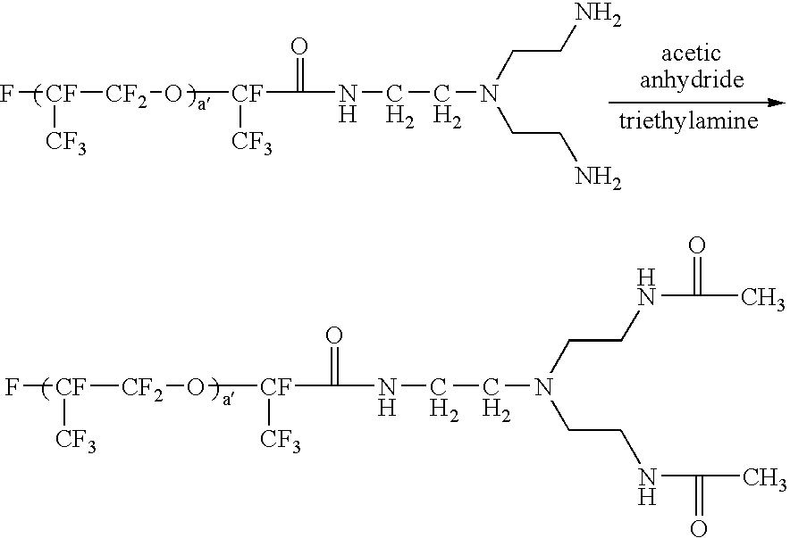
- R f amine 2000 is represented by Formula T-1 wherein R is Formula R, Q is —C(O)NH—, L is —CH 2 CH 2 N(CH 2 CH 2 —) 2 , m is 2, q is 1 and X is —NH 2 .
- R f amide 2000 is represented by Formula T-1 wherein R is Formula R, Q is —C(O)NH—, L is —CH 2 CH 2 N(CH 2 CH 2 —) 2 , m is 2, q is 1 and X is —NHC(O)CH 3 .
- R f amide 2000 is represented by Formula T-1 wherein R is Formula R, Q is —C(O)NH—, L is —CH 2 CH 2 N(CH 2 CH 2 —) 2 , m is 2, q is 1 and X is —NHC(O)CF 3 .
- F8POH and F8C1 are represented by Formula T-2 wherein R is a fluorinated alkyl, m is 1, q is 1, both Q and Q′ are absent, both L and L′ are an alkylene chain, X is a pyridinium ion, Y is OH and the counterions are CF 3 SO 3 ⁇ and a perfluoropolyether substituted carboxylate, respectively.
- the reaction mixture was stirred for at least another 8 hours at room temperature to allow the reaction to complete.
- the reaction mixture was washed with deionized water three times, dried over magnesium sulfate and the solvent was stripped off.
- the crude product was recrystallized from heptane/methylene chloride and rinsed with heptane. 12.45 Grams (yield: 83.6%) of a white crystal (1H, 1H, 2H, 2H-perfluorodecyl triflate) was obtained.
- FNC1 is represented by Formula T-2 wherein R is a fluorinated alkyl, m is 2, q is 1, Q is absent, Q′ is —C(O)N ⁇ , both L and L′ are an alkylene chain, X is a pyridinium ion, Y is OH and the counterion is a fluoropolyether substituted carboxylate.
- the fluorinated Cu phthalocyanine dye was prepared according to U.S. Pat. No. 3,281,426.
- a mixture of copper phthalocyanine (41.0 gm, 71.2 mmole, Aldrich) and 1-iodoperfluorooctane (370 gm, 678 mmole, SynQuest) was added into a 1-gallon pressure reactor (Parr Instrument Co.) with a glass liner. The reactor was vacuum sealed at 1 Torr and heated at 375° C. for 3 days.
- the crude product obtained was mixed with 200 gm of Celite (Fisher Scientific) and extracted with 4 L of PFS-2TM in Soxhlet extractor for 5 days.
- the dark blue solution obtained was washed with 4L of acetone 3 times and evaporated to dryness by rotary evaporation (60° C.) under vacuum ( ⁇ 5 Torr). A dark blue solid was obtained (106 gm, 66% yield).
- the microcup composition was slowly coated onto a 8′′ ⁇ 8′′ electroformed Ni male mold for an array of 90 ⁇ m (length) ⁇ 90 ⁇ m (width) ⁇ 27 ⁇ m (depth) ⁇ 11 ⁇ m (width of top surface of the partition wall between microcups) microcups.
- a plastic blade was used to remove excess of fluid and gently squeeze it into “valleys” of the Ni mold.
- the coated Ni mold was heated in an oven at 65° C.
- An electrophoretic dispersion was filled into the microcup prepared from Preparation 10B using a #0 drawdown bar.
- the filled microcups were then overcoated with a top-sealing/adhesive solution consisting of 11.9 parts (dry) by weight of polyurethane IP9820-15, 2.1 parts by weight of CN983 (urethane diacrylate), 0.1 parts by weight of Irgacure 907 (2-methyl 1-[4-(methylthio)phenyl]2-morpholinopropan-1-one), 40.8 parts by weight of MEK, 40.8 parts by weight of IPAc and 4.3 parts by weight of CHO (cyclohexanone) with a doctor blade.
- a top-sealing/adhesive solution consisting of 11.9 parts (dry) by weight of polyurethane IP9820-15, 2.1 parts by weight of CN983 (urethane diacrylate), 0.1 parts by weight of Irgacure 907 (2-methyl 1-[4-
- the sealing layer was air-dried for 10 minutes and heated in an 80° C. oven for 2 minutes to form a seamless sealing on the filled microcup.
- the targeted (dry) thickness of the sealing layer was about 3 ⁇ 4 microns.
- the top-sealed microcup was laminated directly onto a 5 mil ITO/PET film by a laminator at 120° C. at a linear speed of 20 cm/min. After lamination, the sample was further UV cured by passing through a UV conveyer twice at the speed of 10 ft/min with a UV intensity of 2.56 W/cm 2 (which is equivalent to 0.856 J/cm 2 ).
- the electro-optic response of all exemplified EPDs was measured by bringing an incoming light from an optical fiber cable connected to a light source and illuminating on a display cell prepared in Preparation 10.
- the back side of the display cell was blackened completely by a black paint.
- the reflecting light from the display sample was then collected and converted into electrical signal by a photo-electric detector and finally recorded and displayed on an oscilloscope.
- the intensity of output waveform correlates to the contrast ratio between ON and OFF state of the display and the slope of optical output waveform reflects the response time of the display during switch.
- FIGS. 2 a and 2 b show the electro-optical response of the display measured at ⁇ 20V and ⁇ 7V, respectively.
- Curve A is the electrical input pulse
- Curve B is the optical response signal.
- the amplitude of the optical signal is a measure of the display contrast ratio.
- FIG. 2 a When the display was driven at ⁇ 20V, a strong electro-optical response was observed as shown in FIG. 2 a .
- ⁇ 7V When the display was driven at one-third of the driving voltage, i.e., ⁇ 7V, a moderate electro-optic response was observed as shown in FIG. 2 b .
- the observed moderate signal at ⁇ 7V indicates that the threshold voltage is lower than 7V, the minimum voltage (1 ⁇ 3 of the operation voltage) required to eliminate the cross-bias effect in a passive matrix device driven at ⁇ 21V.
- Fluorolink D10 a Dihydroxy-Terminated Perfluoropolyether
- Fluorolink D10 has the formula of HOH 2 CCF 2 O(CF 2 CF 2 O) m (CF 2 O) n CF 2 CH 2 OH which is Formula T-4 wherein R is a perfluoropolyether moiety, Q and Q′ are absent, both L and L′ are methylene, both X and Y are —OH, both m and m′ are 1 and both q and q′ are 1.
- FIGS. 2 c and 2 d show the electro-optic response of the display of Example 2 driven at ⁇ 20V and ⁇ 7V, respectively.
- the display had a strong electro-optic response when it was driven at ⁇ 20V ( FIG. 2 c ); but no response at all when it was driven at ⁇ 7V ( FIG. 2 d ).
- the lack of electro-optic response at ⁇ 7V indicates a threshold voltage of at least 7V. This implies that a passive matrix display without the undesirable cross-bias effect at an operation voltage of ⁇ 21V or lower is feasible with the electrophoretic fluid of Example 2.
- Comparative Example 1 The same procedure of Comparative Example 1 was followed except that an electrophoretic fluid containing 6 wt % of the TiO 2 -containing microparticles (from Preparation 8) and 1.3 wt % of CuPc-C 8 F 17 dye (from Preparation 6) was used.
- FIG. 3 a shows a strong electro-optic response of Comparative Example 3 driven at ⁇ 15V.
- a weak electro-optic response was observed as shown in FIG. 3 b.
- Comparative Example 1 The same procedure of Comparative Example 1 was followed except that an electrophoretic fluid containing 6 wt % of the TiO 2 -containing microparticles (from Preparation 8), 1.3 wt % of CuPc-C 8 F 17 dye (from Preparation 6) and 0.5 wt % (based on the weight of TiO 2 -containing microparticles used) of R f -amine 2000 (from Preparation 1) was used.
- Comparative Example 1 The same procedure of Comparative Example 1 was followed except that an electrophoretic fluid containing 6 wt % of the TiO 2 -containing microparticles (from Preparation 8), 1.3 wt % of CuPc-C 8 F 17 dye (from Preparation 6), 1.5 wt % (based on the weight of TiO 2 -containing microparticles used) of R f -amine 2000 (from Preparation 1) and 10 wt % of a co-solvent ZT180 (from Solvay Solexis) was used.
- Comparative Example 1 The same procedure of Comparative Example 1 was followed except that an electrophoretic fluid containing 6.4 wt % of the TiO 2 -containing microparticles (from Preparation 8) and 1.66 wt % of CuPc-C 8 F 17 dye (from Preparation 6) was used.
- the EPD was driven at ⁇ 80V with two different frequencies, 0.5 Hz and 2 Hz. As shown in FIGS. 4 a and 4 b , the electro-optic response of the display is not dependent on the frequency of the electrical input pulse.
- Comparative Example 1 The same procedure of Comparative Example 1 was followed except that an electrophoretic fluid containing 6.4 wt % of the TiO 2 -containing microparticles (from Preparation 8), 1.66 wt % of CuPc-C 8 F 17 dye (from Preparation 6), 0.5 wt % (based on the weight of TiO 2 microparticles) of R f trifluoromethylamide 2000 (from Preparation 3) and 10 wt % of co-solvent ZT180 (from Solvay Solexis) was used.
- FIGS. 4 c and 4 d a frequency-dependent electro-optical response at an operation voltage of ⁇ 80V was observed.
- the signal of electro-optical response of the display driven at 0.5 Hz ( FIG. 4 c ) was significantly weaker than that of the display driven at 2 Hz ( FIG. 4 d ). This shows that the cross-bias and/or crosstalk effects of a passive matrix EPD may also be suppressed by adjusting the driving frequency.
- Comparative Example 1 The same procedure of Comparative Example 1 was followed except that an electrophoretic fluid containing 9.7 wt % of the TiO 2 -containing microparticles (from Preparation 8) and 1.24 wt % of CuPc-C 8 F 17 dye (from Preparation 6) was used.
- Comparative Example 1 The same procedure of Comparative Example 1 was followed except that an electrophoretic fluid containing 9.7 wt % of the TiO 2 -containing microparticles (from Preparation 8), 1.24 wt % of CuPC-C 8 F 17 dye (from Preparation 6), 1 wt % (based on the weight of TiO 2 -containing microparticles) of R f trifluoromethylamide 2000 (from Preparation 3) and 10 wt % of co-solvent ZT180 (from Solvay Solexis) was used.
- Comparative Example 1 The same procedure of Comparative Example 1 was followed except that an electrophoretic fluid containing 6.4 wt % of the TiO 2 -containing microparticles (from Preparation 8), 1.66 wt % of CuPc-C 8 F 17 dye (from Preparation 6), 2 wt % (based on the weight of TiO 2 -containing microparticles) of R f trifluoromethylamide 2000 (from Preparation 3) and 10 wt % of co-solvent ZT180 (from Solvay Solexis) was used.
- Comparative Example 1 The same procedure of Comparative Example 1 was followed except that an electrophoretic fluid containing 9.7 wt % of the TiO 2 -containing microparticles (from Preparation 8), 0.6 wt % of CuPc-C 8 F 17 dye (from Preparation 6), 0.5 wt % of SiPc-C 8 F 17 dye (from Preparation 7), 1 wt % (based on the weight of TiO 2 -containing microparticles) of R f trifluoromethylamide 2000 (from Preparation 3) and 10 wt % of co-solvent ZT180 (from Solvay Solexis) was used.
- an electrophoretic fluid containing 9.7 wt % of the TiO 2 -containing microparticles from Preparation 8
- 0.6 wt % of CuPc-C 8 F 17 dye from Preparation 6
- 0.5 wt % of SiPc-C 8 F 17 dye from Preparation 7
- 1 wt %
- the EPD displays of Comparative Example 8 and Examples 9-10 were driven at 0.2 Hz electrical pulsing waveform with different driving voltages sweeping from ⁇ 10V to ⁇ 60V.
- the contrast ratios (calculated from the Dmax and Dmin measured by GretagMacBethTM Spectrolino Spectrometer using a square electrical waveform) of the display versus different driving voltages are shown in FIG. 5 .
- the Curve ( 5 a ) no threshold voltage phenomenon (with contrast ratio well above 1 at ⁇ 10V) was observed for the EPD of Comparative Example 8.
- the contrast ratio and gamma of the display of Example 9 can be further improved significantly with the threshold voltage maintained essentially at the same level (about 15 V) by replacing the 1.24 wt % of CuPc-C 8 F 17 dye with a dye mixture containing 0.5 wt % SiPc-C 8 F 17 and 0.6 wt % of the CuPc-C8F 17 (Example 11, Curve 6 b in FIG. 6 ).
- the concentrations of the two dyes of Example 11 were selected to match the optical density of the 1.24 wt % of CuPc-C 8 F 17 dye solution in HT200.
- FIG. 7 a and FIG. 7 b show the electro-optical response of the EPD display of Comparative Example 8 measured at ⁇ 45V/0.2 Hz and ⁇ 15V/0.2 Hz, respectively.
- FIG. 7 c and FIG. 7 d show the electro-optical response of the display of Example 11 also measured at ⁇ 45V/0.2 Hz and ⁇ 15V/0.2 Hz, respectively. It is evident that the both threshold characteristics and switching performance of the display of Example 11 were greatly improved as compared to those of the Comparative Example 8.
- Comparative Example 1 The same procedure of Comparative Example 1 was followed except that an electrophoretic fluid containing 9.7 wt % of the TiO 2 -containing microparticles (from Preparation 8), and 1.24 wt % of CuPc-C 8 F 17 dye (from Preparation 6) was used.
- Comparative Example 1 The same procedure of Comparative Example 1 was followed except that an electrophoretic fluid containing 9.7 wt % of the TiO 2 -containing microparticles (from Preparation 8), 1.24 wt % of CuPc-C 8 F 17 dye (from Preparation 6), 1 wt % (based on the weight of TiO 2 -containing microparticles) of R f amine 2000 (from Preparation 1) and 10 wt % of co-solvent ZT180 (from Solvay Solexis) was used.
- Comparative Example 1 The same procedure of Comparative Example 1 was followed except that an electrophoretic fluid containing 9.7 wt % of the TiO 2 -containing microparticles (from Preparation 8), 1.24 wt % of CuPc-C 8 F 17 dye (from Preparation 6), 2 wt % (based on the weight of TiO 2 -containing microparticles) of R f amine 2000 (from Preparation 1) and 10 wt % of co-solvent ZT180 (from Solvay Solexis) was used.
- the contrast ratios of the displays of Examples 12-14 as a function of driving voltage at 0.2 Hz are shown in FIG. 8 .
- the display of the Comparative Example 12 shows a low contrast ratio with no observable threshold characteristics (Curve 8a).
- the addition of 1 wt % (Curve 8b, Example 13) and 2 wt % (Curve 8c, Example 14) of R f amine 2000 based on the weight of TiO 2 -containing microparticles significantly improves the contrast ratio and threshold characteristics.
- a threshold voltage of about 15V as well as a sharp gamma were obtained. No deterioration of switching rate was observed.
- Comparative Example 1 The same procedure of Comparative Example 1 was followed except that an electrophoretic fluid containing 6 wt % of the TiO 2 -containing microparticles (from Preparation 9) and 1.36 wt % of CuPc-C 8 F 17 dye (from Preparation 6) was used.
- Comparative Example 1 The same procedure of Comparative Example 1 was followed except that an electrophoretic fluid containing 6 wt % of the TiO 2 -containing microparticles (from Preparation 9), 1.36 wt % of CuPc-C 8 F 17 dye (from Preparation 6) and 3.3 wt % (based on the total weight of TiO 2 -containing microparticles) of F8C1 (from Preparation 4) was used.
- FIGS. 9 c and 9 d a strong electro-optical response was observed at ⁇ 45V/0.2 Hz ( FIG. 9 c ), but no response was observed at all at ⁇ 15V/0.2 Hz ( FIG. 9 d ).
- Comparative Example 1 The same procedure of Comparative Example 1 was followed except that an electrophoretic fluid containing 6 wt % of the TiO 2 -containing microparticles (from Preparation 9), 1.36 wt % of CuPc-C 8 F 17 dye (from Preparation 6), and 1.6 wt % (based on the total weight of TiO 2 -containing microparticles) of FNC1 (from Preparation 5) was used.
- FIGS. 9 e and 9 f a strong electro-optic response at ⁇ 45V/0.2 Hz was observed ( FIG. 9 e ), but no response was observed at all at ⁇ 15V/0.2 Hz ( FIG. 9 f ).
Abstract
Description

wherein:
- each n is individually 0-4 for silicon phthalocyanine (I) or 0-6 for silicon naphthalocyanine (II);
- R1 is independently Rf-A- (wherein Rf is as defined below and A is a single bond, —CH2O—, —CH2CH2— or —CO—), alkyl, heteroalkyl, aryl, heteroaryl, alkylaryl, arylalkyl, R′O—, R′S—, R′R″N—, R′CO—, R′OCO—, R′COO—, R′CONR″—, R′R″NCO—, R′NHCONR″—, R′SO2NR″— or R′R″NSO2— (in which R′ and R″ are independently hydrogen, Rf (as defined below), alkyl, heteroalkyl, aryl, heteroaryl, alkylaryl, arylalkyl) or halogenated, particularly fluorinated derivatives thereof;
- Z is O or NR′ wherein R′ is defined as above;
- R2 is hydrogen, Rf-B- (wherein Rf is as defined below and B is a single bond, —CH2— or —CH2CH2—), alkyl, heteroalkyl or halogenated, particularly fluorinated derivatives thereof, or —SiR3R4R5 wherein R3, R4, and R5 are independently an alkyl or fluoroalkyl group of 1 to 20 carbon atoms or alkoxy or fluoroalkoxy of 2 to 40 carbon atoms; and
- Rf is a low molecular weight (100-100,000) fluorinated polymeric or oligomeric moiety prepared from one or more types of fluorinated monomers.

wherein R1 is a fluorinated polymer or oligomeric chain or a fluorinated alkyl of 1 to 18 carbon atoms, preferably 4-12 carbon atoms; t, u, v and w are independently 0-4 and t+u+v+w≧3. More preferably, t, u, v and w are all 1.
R-[Q-L-(X)m]q (T-1)
R-[Q-L-X-Q′-(L′-Y)m]q (T-2)
R-[Q-L-(X-Q′-L′-Y)m]q (T-3)
[(X)m-L-Q]q-R-[Q′-L′-(Y)m′]q′ (T-4)
wherein:
- m and m′ are independently natural numbers which are ≧1, preferably 1 or 2;
- q and q′ are independently natural numbers which are ≧1, preferably from 1 to 10, more preferably 1 or 2;
- R is a halogenated group, preferably fluorinated alkyl, fluorinated aryl, fluoroaryl-alkyl, aryl-fluoroalkyl, fluoroalkyl-aryl, alkyl-fluoroaryl or a halogenated, particularly fluorinated, polymeric or oligomeric chain;
- Q and L or Q′ and L′ together forming a linking chain for linking the main chain (R) to the functional group, X or Y, or for linking the functional groups X and Y;
- X and Y are independently functional groups capable of forming hydrogen bonding, acid-base interaction, donor-acceptor interaction, metal-ligand interaction or Coulombic interaction.

wherein the open substituent positions (not designated) on the main chain of Formula R can be the same or different and may independently be selected from a group consisting of hydrogen, halogen (especially fluoro), alkyl, alkenyl, aryl, alkylaryl, fluoroalkyl, fluoroalkenyl, fluoroaryl, fluoroalkylaryl, —OR10, OCOR10, —COOR10, —CONR10R11 (wherein R10 and R11 are independently hydrogen, alkyl, aryl, alkylaryl, fluoroalkyl, fluoroaryl, fluoroalkylaryl or fluorinated polyether) and substituted derivatives thereof;
- Z1, Z2, and Z3 are independently oxygen or absent; and
- a′, b′ and c′ are the weight fractions of the corresponding repeating units and are independently in the range of 0-1 with their sum no greater than 1.


| Weight | ||
| Component | Part | Source |
| EB 600 | 35.927 | UCB |
| SR 399 | 34.941 | Sartomer |
| HDDA | 22.337 | UCB |
| EB1360 | 6.503 | UCB |
| Irgacure 369 | 0.217 | Ciba |
| Sarcure SR1124 | 0.043 | Sartomer |
| Antioxidant Ir1035 | 0.033 | Ciba |
Claims (24)
R-[Q-L-(X)m]q (T-1)

Priority Applications (2)
| Application Number | Priority Date | Filing Date | Title |
|---|---|---|---|
| US10/683,869 US7226550B2 (en) | 2002-10-10 | 2003-10-09 | Electrophoretic dispersions |
| US11/734,170 US7767112B2 (en) | 2002-10-10 | 2007-04-11 | Method for inducing or enhancing the threshold voltage of an electrophoretic display |
Applications Claiming Priority (2)
| Application Number | Priority Date | Filing Date | Title |
|---|---|---|---|
| US41776202P | 2002-10-10 | 2002-10-10 | |
| US10/683,869 US7226550B2 (en) | 2002-10-10 | 2003-10-09 | Electrophoretic dispersions |
Related Child Applications (1)
| Application Number | Title | Priority Date | Filing Date |
|---|---|---|---|
| US11/734,170 Division US7767112B2 (en) | 2002-10-10 | 2007-04-11 | Method for inducing or enhancing the threshold voltage of an electrophoretic display |
Publications (2)
| Publication Number | Publication Date |
|---|---|
| US20040131959A1 US20040131959A1 (en) | 2004-07-08 |
| US7226550B2 true US7226550B2 (en) | 2007-06-05 |
Family
ID=32094081
Family Applications (2)
| Application Number | Title | Priority Date | Filing Date |
|---|---|---|---|
| US10/683,869 Expired - Fee Related US7226550B2 (en) | 2002-10-10 | 2003-10-09 | Electrophoretic dispersions |
| US11/734,170 Expired - Fee Related US7767112B2 (en) | 2002-10-10 | 2007-04-11 | Method for inducing or enhancing the threshold voltage of an electrophoretic display |
Family Applications After (1)
| Application Number | Title | Priority Date | Filing Date |
|---|---|---|---|
| US11/734,170 Expired - Fee Related US7767112B2 (en) | 2002-10-10 | 2007-04-11 | Method for inducing or enhancing the threshold voltage of an electrophoretic display |
Country Status (5)
| Country | Link |
|---|---|
| US (2) | US7226550B2 (en) |
| CN (1) | CN100371820C (en) |
| AU (1) | AU2003279255A1 (en) |
| TW (1) | TWI293715B (en) |
| WO (1) | WO2004034139A1 (en) |
Cited By (87)
| Publication number | Priority date | Publication date | Assignee | Title |
|---|---|---|---|---|
| US20080165411A1 (en) * | 2004-05-12 | 2008-07-10 | Xiaojia Wang | Process for the manufacture of electrophoretic displays |
| US20090315824A1 (en) * | 2008-05-13 | 2009-12-24 | Seiko Epson Corporation | Electrophoretic display sheet, electrophoretic display apparatus, and electronic device |
| US20100101952A1 (en) * | 2008-10-29 | 2010-04-29 | Gary Gibson | Electrophoretic cell and method employing differential mobility |
| US20100165448A1 (en) * | 2008-12-30 | 2010-07-01 | Sprague Robert A | Multicolor display architecture using enhanced dark state |
| US20100165005A1 (en) * | 2008-12-30 | 2010-07-01 | Sprague Robert A | Highlight color display architecture using enhanced dark state |
| WO2010089058A1 (en) | 2009-02-09 | 2010-08-12 | Merck Patent Gmbh, | Coloured particles for electrophoretic displays |
| WO2010089059A1 (en) | 2009-02-09 | 2010-08-12 | Merck Patent Gmbh | Coloured particles for electrophoretic displays |
| WO2010089060A2 (en) | 2009-02-09 | 2010-08-12 | Merck Patent Gmbh | Particles for electrophoretic displays |
| WO2010089057A2 (en) | 2009-02-09 | 2010-08-12 | Merck Patent Gmbh | Particles for electrophoretic displays |
| US20100288639A1 (en) * | 2004-05-12 | 2010-11-18 | Xiaojia Wang | Process for the manufacture of electrophoretic displays |
| US20110000605A1 (en) * | 2000-03-03 | 2011-01-06 | Rong-Chang Liang | Electrophoretic display and process for its manufacture |
| US20110053958A1 (en) * | 2008-03-18 | 2011-03-03 | Arena Pharmaceuticals, Inc. | Modulators of the prostacyclin (pgi2) receptor useful for the treatment of disorders related thereto |
| US20110217639A1 (en) * | 2010-03-02 | 2011-09-08 | Sprague Robert A | Electrophoretic display fluid |
| US20110217896A1 (en) * | 2000-03-03 | 2011-09-08 | Rong-Chang Liang | Process for preparing a display panel |
| US20110224262A1 (en) * | 2008-11-26 | 2011-09-15 | Arena Pharmaceuticals, Inc. | Pyrazolyl substituted carbonic acid derivatives as modulators of the prostacyclin (pgi2) receptor useful for the treatment of disorders related thereto |
| WO2011154103A1 (en) | 2010-06-07 | 2011-12-15 | Merck Patent Gmbh | Coloured polymer particles |
| WO2011154104A1 (en) | 2010-06-07 | 2011-12-15 | Merck Patent Gmbh | White reflective polymer particles |
| WO2012019704A1 (en) | 2010-08-07 | 2012-02-16 | Merck Patent Gmbh | Particles for electrophoretic displays |
| WO2012072218A1 (en) | 2010-11-30 | 2012-06-07 | Merck Patent Gmbh | Particles for electrophoretic displays |
| WO2012152409A1 (en) | 2011-05-09 | 2012-11-15 | Merck Patent Gmbh | Reactive mesogen based polymer particles |
| WO2012152392A1 (en) | 2011-05-09 | 2012-11-15 | Merck Patent Gmbh | Particles for electrophoretic displays |
| WO2013026519A1 (en) | 2011-08-24 | 2013-02-28 | Merck Patent Gmbh | Coloured polymer particles |
| WO2013079146A1 (en) | 2011-11-30 | 2013-06-06 | Merck Patent Gmbh | Particles for electrophoretic displays |
| WO2013079158A1 (en) | 2011-11-30 | 2013-06-06 | Merck Patent Gmbh | Electrophoretic fluids |
| WO2013149714A1 (en) | 2012-04-04 | 2013-10-10 | Merck Patent Gmbh | Particles for electrophoretic displays comprising a core and a random - copolymer coating |
| WO2013170936A1 (en) | 2012-05-14 | 2013-11-21 | Merck Patent Gmbh | Particles for electrophoretic displays |
| WO2013170937A1 (en) | 2012-05-14 | 2013-11-21 | Merck Patent Gmbh | Particles for electrophoretic displays |
| WO2013170932A1 (en) | 2012-05-14 | 2013-11-21 | Merck Patent Gmbh | Particles for electrophoretic displays |
| WO2013170935A1 (en) | 2012-05-14 | 2013-11-21 | Merck Patent Gmbh | Particles for electrophoretic displays |
| WO2013170934A1 (en) | 2012-05-14 | 2013-11-21 | Merck Patent Gmbh | Particles for electrophoretic displays |
| WO2013170938A1 (en) | 2012-05-14 | 2013-11-21 | Merck Patent Gmbh | Particles for electrophoretic displays |
| WO2013170933A1 (en) | 2012-05-14 | 2013-11-21 | Merck Patent Gmbh | Particles for electrophoretic displays |
| US8605354B2 (en) | 2011-09-02 | 2013-12-10 | Sipix Imaging, Inc. | Color display devices |
| WO2013189580A1 (en) | 2012-06-22 | 2013-12-27 | Merck Patent Gmbh | Electrophoretic fluid |
| WO2014019650A1 (en) | 2012-08-01 | 2014-02-06 | Merck Patent Gmbh | Electrophoretic fluids |
| WO2014019651A1 (en) | 2012-08-01 | 2014-02-06 | Merck Patent Gmbh | Electrophoretic fluids |
| US8649084B2 (en) | 2011-09-02 | 2014-02-11 | Sipix Imaging, Inc. | Color display devices |
| US8704756B2 (en) | 2010-05-26 | 2014-04-22 | Sipix Imaging, Inc. | Color display architecture and driving methods |
| US8717664B2 (en) | 2012-10-02 | 2014-05-06 | Sipix Imaging, Inc. | Color display device |
| US8786935B2 (en) | 2011-06-02 | 2014-07-22 | Sipix Imaging, Inc. | Color electrophoretic display |
| US8797636B2 (en) | 2012-07-17 | 2014-08-05 | Sipix Imaging, Inc. | Light-enhancing structure for electrophoretic display |
| US8810899B2 (en) | 2008-04-03 | 2014-08-19 | E Ink California, Llc | Color display devices |
| US20140240815A1 (en) * | 2013-02-28 | 2014-08-28 | Fuji Xerox Co., Ltd. | Particles for display, particle dispersion for display, display medium, and display device |
| WO2014166583A1 (en) | 2013-04-12 | 2014-10-16 | Merck Patent Gmbh | Particles for electrophoretic displays |
| WO2014198373A1 (en) | 2013-06-12 | 2014-12-18 | Merck Patent Gmbh | Particles for electrophoretic displays |
| US8917439B2 (en) | 2012-02-09 | 2014-12-23 | E Ink California, Llc | Shutter mode for color display devices |
| US8940891B2 (en) | 2008-12-08 | 2015-01-27 | Arena Pharmaceuticals, Inc. | Modulators of the prostacyclin (PGI2) receptor useful for the treatment of disorders related thereto |
| US8964282B2 (en) | 2012-10-02 | 2015-02-24 | E Ink California, Llc | Color display device |
| US9013783B2 (en) | 2011-06-02 | 2015-04-21 | E Ink California, Llc | Color electrophoretic display |
| WO2015082048A2 (en) | 2013-12-02 | 2015-06-11 | Merck Patent Gmbh | Black polymer particles |
| WO2015082047A1 (en) | 2013-12-02 | 2015-06-11 | Merck Patent Gmbh | Coloured or black particles |
| US9116412B2 (en) | 2010-05-26 | 2015-08-25 | E Ink California, Llc | Color display architecture and driving methods |
| US9140952B2 (en) | 2010-04-22 | 2015-09-22 | E Ink California, Llc | Electrophoretic display with enhanced contrast |
| US9170468B2 (en) | 2013-05-17 | 2015-10-27 | E Ink California, Llc | Color display device |
| US9251736B2 (en) | 2009-01-30 | 2016-02-02 | E Ink California, Llc | Multiple voltage level driving for electrophoretic displays |
| US9285649B2 (en) | 2013-04-18 | 2016-03-15 | E Ink California, Llc | Color display device |
| US9360733B2 (en) | 2012-10-02 | 2016-06-07 | E Ink California, Llc | Color display device |
| WO2016096080A1 (en) | 2014-12-19 | 2016-06-23 | Merck Patent Gmbh | Particles for electrophoretic displays |
| WO2016096085A1 (en) | 2014-12-19 | 2016-06-23 | Merck Patent Gmbh | Particles for electrophoretic displays |
| US9459510B2 (en) | 2013-05-17 | 2016-10-04 | E Ink California, Llc | Color display device with color filters |
| US9513527B2 (en) | 2014-01-14 | 2016-12-06 | E Ink California, Llc | Color display device |
| US9541814B2 (en) | 2014-02-19 | 2017-01-10 | E Ink California, Llc | Color display device |
| US9646547B2 (en) | 2013-05-17 | 2017-05-09 | E Ink California, Llc | Color display device |
| US9759981B2 (en) | 2014-03-18 | 2017-09-12 | E Ink California, Llc | Color display device |
| US9977309B2 (en) | 2013-12-19 | 2018-05-22 | Merck Patent Gmbh | Electrophoretic fluid |
| US9995987B1 (en) | 2017-03-20 | 2018-06-12 | E Ink Corporation | Composite particles and method for making the same |
| US10147366B2 (en) | 2014-11-17 | 2018-12-04 | E Ink California, Llc | Methods for driving four particle electrophoretic display |
| US10162242B2 (en) | 2013-10-11 | 2018-12-25 | E Ink California, Llc | Color display device |
| US10254622B2 (en) | 2017-02-15 | 2019-04-09 | E Ink California, Llc | Polymer additives used in color electrophoretic display medium |
| US10308744B2 (en) | 2013-06-12 | 2019-06-04 | Merck Patent Gmbh | Particles for electrophoretic displays |
| US10380955B2 (en) | 2014-07-09 | 2019-08-13 | E Ink California, Llc | Color display device and driving methods therefor |
| US10435566B2 (en) | 2014-12-19 | 2019-10-08 | Merck Patent Gmbh | Particles for electrophoretic displays |
| US10537546B2 (en) | 2014-10-23 | 2020-01-21 | Arena Pharmaceuticals, Inc. | Method of treating conditions related to the PGI2 receptor |
| US10809590B2 (en) | 2017-06-16 | 2020-10-20 | E Ink Corporation | Variable transmission electrophoretic devices |
| US10891906B2 (en) | 2014-07-09 | 2021-01-12 | E Ink California, Llc | Color display device and driving methods therefor |
| US10921676B2 (en) | 2017-08-30 | 2021-02-16 | E Ink Corporation | Electrophoretic medium |
| US10969648B2 (en) | 2017-12-22 | 2021-04-06 | E Ink Corporation | Electrophoretic display device and electronic apparatus |
| US10983410B2 (en) | 2017-06-16 | 2021-04-20 | E Ink Corporation | Electro-optic media including encapsulated pigments in gelatin binder |
| US11123298B2 (en) | 2017-03-01 | 2021-09-21 | Arena Pharmaceuticals, Inc. | Compositions comprising PGI2-receptor agonists and processes for the preparation thereof |
| US11175561B1 (en) | 2018-04-12 | 2021-11-16 | E Ink Corporation | Electrophoretic display media with network electrodes and methods of making and using the same |
| US11248122B2 (en) | 2017-12-30 | 2022-02-15 | E Ink Corporation | Pigments for electrophoretic displays |
| US11266832B2 (en) | 2017-11-14 | 2022-03-08 | E Ink California, Llc | Electrophoretic active delivery system including porous conductive electrode layer |
| US11520210B2 (en) | 2019-09-30 | 2022-12-06 | E Ink Corporation | Electrically-actuated variable transmission film having very low haze and a visible grid in a clear state |
| US11567388B2 (en) | 2019-02-25 | 2023-01-31 | E Ink Corporation | Composite electrophoretic particles and variable transmission films containing the same |
| US11708720B2 (en) | 2013-10-22 | 2023-07-25 | E Ink Corporation | Light-modulating electrophoretic device |
| US11754903B1 (en) | 2018-11-16 | 2023-09-12 | E Ink Corporation | Electro-optic assemblies and materials for use therein |
| US11938214B2 (en) | 2019-11-27 | 2024-03-26 | E Ink Corporation | Benefit agent delivery system comprising microcells having an electrically eroding sealing layer |
Families Citing this family (23)
| Publication number | Priority date | Publication date | Assignee | Title |
|---|---|---|---|---|
| US7557981B2 (en) * | 2000-03-03 | 2009-07-07 | Sipix Imaging, Inc. | Electrophoretic display and process for its manufacture |
| US7233429B2 (en) * | 2000-03-03 | 2007-06-19 | Sipix Imaging, Inc. | Electrophoretic display |
| US6831770B2 (en) * | 2000-03-03 | 2004-12-14 | Sipix Imaging, Inc. | Electrophoretic display and novel process for its manufacture |
| US7158282B2 (en) * | 2000-03-03 | 2007-01-02 | Sipix Imaging, Inc. | Electrophoretic display and novel process for its manufacture |
| JP2004198973A (en) * | 2002-12-20 | 2004-07-15 | Fuji Xerox Co Ltd | Particle for display device, image display medium, and image forming apparatus |
| US7061662B2 (en) * | 2003-10-07 | 2006-06-13 | Sipix Imaging, Inc. | Electrophoretic display with thermal control |
| US8514168B2 (en) * | 2003-10-07 | 2013-08-20 | Sipix Imaging, Inc. | Electrophoretic display with thermal control |
| US8377586B2 (en) | 2005-10-05 | 2013-02-19 | California Institute Of Technology | Fluoride ion electrochemical cell |
| KR101256023B1 (en) * | 2006-10-31 | 2013-04-18 | 삼성디스플레이 주식회사 | Electrophoretic display and the manufacturing method thereof |
| US20110105643A1 (en) * | 2009-10-29 | 2011-05-05 | Doris Pik-Yiu Chun | Polymer-encapsulated nanoparticles |
| US8907046B2 (en) | 2009-12-30 | 2014-12-09 | 3M Innovative Properties Company | Copolymers with perfluoropolyether segment and multiple aminooxalylamino groups |
| CN102712758B (en) | 2009-12-30 | 2014-05-07 | 3M创新有限公司 | Methods of making polydiorganosiloxane polyoxamide copolymers |
| WO2011082067A2 (en) | 2009-12-30 | 2011-07-07 | 3M Innovative Properties Company | Perfluoropolyether-containing compounds with oxalylamino groups |
| WO2011082063A1 (en) | 2009-12-30 | 2011-07-07 | 3M Innovative Properties Company | Copolymers with perfluorpolyether segment and polydiorganosiloxane segment |
| TWI424226B (en) * | 2010-04-22 | 2014-01-21 | Au Optronics Corp | Planar light source and display panel |
| JP6014779B2 (en) | 2013-03-11 | 2016-10-25 | サウジ ベイシック インダストリーズ コーポレイション | Group III metal aryloxy-phthalocyanines |
| CN105051049A (en) | 2013-03-11 | 2015-11-11 | 沙特基础工业公司 | Aryloxy-phthalocyanines of group IV metals for use in solar cells |
| US8957490B2 (en) * | 2013-06-28 | 2015-02-17 | Infineon Technologies Dresden Gmbh | Silicon light trap devices |
| US20160349593A1 (en) * | 2015-05-28 | 2016-12-01 | E Ink California, Llc | Charge control agent for electrophoretic display |
| US10040954B2 (en) | 2015-05-28 | 2018-08-07 | E Ink California, Llc | Electrophoretic medium comprising a mixture of charge control agents |
| JP2018523727A (en) * | 2015-07-23 | 2018-08-23 | イー インク コーポレイション | Polymer formulation for use with electro-optic media |
| JP2017187615A (en) * | 2016-04-05 | 2017-10-12 | セイコーエプソン株式会社 | Electrophoretic dispersion liquid, production method of electrophoretic dispersion liquid, electrophoretic sheet, electrophoretic device and electronic apparatus |
| CN106883808B (en) * | 2017-04-01 | 2021-02-12 | 广州奥翼电子科技股份有限公司 | Adhesive, preparation method thereof and electrophoretic display |
Citations (40)
| Publication number | Priority date | Publication date | Assignee | Title |
|---|---|---|---|---|
| US3006921A (en) | 1957-12-31 | 1961-10-31 | Du Pont | Trifluoromethyl substituted phthalocyanines |
| US3281426A (en) | 1961-05-01 | 1966-10-25 | Minnesota Mining & Mfg | Perfluoroalkylated phthalic anhydride, copper phthalocyanine and their preparation |
| US3612758A (en) | 1969-10-03 | 1971-10-12 | Xerox Corp | Color display device |
| US3870517A (en) | 1969-10-18 | 1975-03-11 | Matsushita Electric Ind Co Ltd | Color image reproduction sheet employed in photoelectrophoretic imaging |
| US4059451A (en) | 1976-07-12 | 1977-11-22 | Matsushita Electric Industrial Co., Ltd. | Electroless copper plating solution |
| US4077936A (en) * | 1974-09-12 | 1978-03-07 | Matsushita Electric Industrial Co., Ltd. | Liquid suspending medium for electrophoretic image display/and or recording device |
| US4085137A (en) | 1969-03-10 | 1978-04-18 | Minnesota Mining And Manufacturing Company | Poly(perfluoroalkylene oxide) derivatives |
| US4093534A (en) | 1974-02-12 | 1978-06-06 | Plessey Handel Und Investments Ag | Working fluids for electrophoretic image display devices |
| US4094911A (en) | 1969-03-10 | 1978-06-13 | Minnesota Mining And Manufacturing Company | Poly(perfluoroalkylene oxide) derivatives |
| US4285801A (en) * | 1979-09-20 | 1981-08-25 | Xerox Corporation | Electrophoretic display composition |
| US4655897A (en) | 1984-11-13 | 1987-04-07 | Copytele, Inc. | Electrophoretic display panels and associated methods |
| US4772103A (en) | 1985-06-10 | 1988-09-20 | Research Frontiers Incorporated | Light valve containing an improved suspension, and liquids therefor |
| US5177476A (en) | 1989-11-24 | 1993-01-05 | Copytele, Inc. | Methods of fabricating dual anode, flat panel electrophoretic displays |
| US5260435A (en) | 1990-07-23 | 1993-11-09 | Nippon Oil And Fats Co., Ltd. | Derivative of naphthalocyanine containing perfluoroalkyl group, process for preparing the same and optical recording medium |
| US5460688A (en) | 1989-05-01 | 1995-10-24 | Copytele, Inc. | Dual anode flat panel electrophoretic display apparatus |
| US5573711A (en) | 1994-05-26 | 1996-11-12 | Copytele, Inc. | Planar fluorinated dielectric suspensions for electrophoretic image displays and related methods |
| US5930026A (en) | 1996-10-25 | 1999-07-27 | Massachusetts Institute Of Technology | Nonemissive displays and piezoelectric power supplies therefor |
| US5961804A (en) | 1997-03-18 | 1999-10-05 | Massachusetts Institute Of Technology | Microencapsulated electrophoretic display |
| US6084057A (en) | 1997-05-20 | 2000-07-04 | Elsicon, Inc. | Polarizable amines and polyimides for optical alignment of liquid crystals |
| US6162521A (en) | 1997-12-05 | 2000-12-19 | Seagate Technology Llc | Fluoropolyether amide lubricants for an information storage system and a method of making the same |
| US6187954B1 (en) | 1999-07-15 | 2001-02-13 | Seagate Technology Llc | Synthesis of fluorinated amides |
| US6239896B1 (en) | 1998-06-01 | 2001-05-29 | Canon Kabushiki Kaisha | Electrophotographic display device and driving method therefor |
| US6262833B1 (en) | 1998-10-07 | 2001-07-17 | E Ink Corporation | Capsules for electrophoretic displays and methods for making the same |
| WO2001067170A1 (en) | 2000-03-03 | 2001-09-13 | Sipix Imaging, Inc. | Electrophoretic display |
| WO2002001281A2 (en) | 2000-06-28 | 2002-01-03 | Sipix Imaging, Inc. | Manufacturing process for electrophoretic display |
| WO2002065215A2 (en) | 2001-02-15 | 2002-08-22 | Sipix Imaging, Inc. | Process for roll-to-roll manufacture of a display by synchronized photolithographic exposure on a substrate web |
| WO2003023510A1 (en) | 2001-09-12 | 2003-03-20 | Sipix Imaging, Inc. | Electrophoretic display with in-plane gating electrodes |
| US6549327B2 (en) | 2001-05-24 | 2003-04-15 | Xerox Corporation | Photochromic gyricon display |
| WO2003038512A1 (en) | 2001-10-29 | 2003-05-08 | Sipix Imaging, Inc. | A vertically-switching electrophoretic display with holding electrodes |
| WO2003058335A2 (en) | 2002-01-03 | 2003-07-17 | Sipix Imaging, Inc. | A novel electrophoretic dispersion with a fluorinated solvent and a charge controlling agent |
| WO2003057360A1 (en) | 2002-01-03 | 2003-07-17 | Sipix Imaging, Inc. | Functionalized halogenated polymers for microencapsulation |
| WO2003069403A1 (en) | 2002-02-11 | 2003-08-21 | Sipix Imaging, Inc. | Core-shell particles for electrophoretic display |
| US6693620B1 (en) | 1999-05-03 | 2004-02-17 | E Ink Corporation | Threshold addressing of electrophoretic displays |
| WO2004068234A1 (en) | 2003-01-30 | 2004-08-12 | Sipix Imaging, Inc. | High performance capsules for electrophoretic displays |
| US6822782B2 (en) | 2001-05-15 | 2004-11-23 | E Ink Corporation | Electrophoretic particles and processes for the production thereof |
| US20050039274A1 (en) | 2003-08-08 | 2005-02-24 | Jin Yang | Fluorinated dyes or colorants and their uses |
| US20050136347A1 (en) * | 2003-11-04 | 2005-06-23 | Haiyan Gu | Electrophoretic dispersions |
| US6933098B2 (en) * | 2000-01-11 | 2005-08-23 | Sipix Imaging Inc. | Process for roll-to-roll manufacture of a display by synchronized photolithographic exposure on a substrate web |
| US20050227155A1 (en) * | 2004-04-13 | 2005-10-13 | Canon Kabushiki Kaisha | Electrophoretic particles, electrophoretic dispersion liquid, and electrophoretic display device |
| US20050264868A1 (en) * | 2003-11-04 | 2005-12-01 | Hwang Jiunn J | Electrophoretic compositions |
Family Cites Families (7)
| Publication number | Priority date | Publication date | Assignee | Title |
|---|---|---|---|---|
| GB1492983A (en) | 1974-02-12 | 1977-11-23 | Plessey Co Ltd | Working fluids for electrophoretic image display devices |
| US4620916A (en) | 1985-09-19 | 1986-11-04 | Zwemer Dirk A | Degradation retardants for electrophoretic display devices |
| DE60120315T2 (en) * | 2000-10-04 | 2007-05-16 | Seiko Epson Corp. | Electrophoretic device and its production method |
| US6650463B2 (en) | 2001-03-13 | 2003-11-18 | Seiko Epson Corporation | Electrophoretic display device |
| TW539928B (en) * | 2001-08-20 | 2003-07-01 | Sipix Imaging Inc | An improved transflective electrophoretic display |
| TWI329662B (en) | 2002-05-17 | 2010-09-01 | Sipix Imaging Inc | Novel fluorinated silicon (iv) phthalocyanines and naphthalocyanines for electrophoretic, magnetophoretic or electromagnetophoretic display |
| TWI315439B (en) | 2002-07-30 | 2009-10-01 | Sipix Imaging Inc | Novel microencapsulation processes and composition for electrophoretic displays |
-
2002
- 2002-12-26 TW TW091137437A patent/TWI293715B/en not_active IP Right Cessation
-
2003
- 2003-03-19 CN CNB031207820A patent/CN100371820C/en not_active Expired - Fee Related
- 2003-10-09 US US10/683,869 patent/US7226550B2/en not_active Expired - Fee Related
- 2003-10-09 WO PCT/US2003/032371 patent/WO2004034139A1/en not_active Application Discontinuation
- 2003-10-09 AU AU2003279255A patent/AU2003279255A1/en not_active Abandoned
-
2007
- 2007-04-11 US US11/734,170 patent/US7767112B2/en not_active Expired - Fee Related
Patent Citations (45)
| Publication number | Priority date | Publication date | Assignee | Title |
|---|---|---|---|---|
| US3006921A (en) | 1957-12-31 | 1961-10-31 | Du Pont | Trifluoromethyl substituted phthalocyanines |
| US3281426A (en) | 1961-05-01 | 1966-10-25 | Minnesota Mining & Mfg | Perfluoroalkylated phthalic anhydride, copper phthalocyanine and their preparation |
| US4085137A (en) | 1969-03-10 | 1978-04-18 | Minnesota Mining And Manufacturing Company | Poly(perfluoroalkylene oxide) derivatives |
| US4094911A (en) | 1969-03-10 | 1978-06-13 | Minnesota Mining And Manufacturing Company | Poly(perfluoroalkylene oxide) derivatives |
| US3612758A (en) | 1969-10-03 | 1971-10-12 | Xerox Corp | Color display device |
| US3870517A (en) | 1969-10-18 | 1975-03-11 | Matsushita Electric Ind Co Ltd | Color image reproduction sheet employed in photoelectrophoretic imaging |
| US4093534A (en) | 1974-02-12 | 1978-06-06 | Plessey Handel Und Investments Ag | Working fluids for electrophoretic image display devices |
| US4077936A (en) * | 1974-09-12 | 1978-03-07 | Matsushita Electric Industrial Co., Ltd. | Liquid suspending medium for electrophoretic image display/and or recording device |
| US4059451A (en) | 1976-07-12 | 1977-11-22 | Matsushita Electric Industrial Co., Ltd. | Electroless copper plating solution |
| US4285801A (en) * | 1979-09-20 | 1981-08-25 | Xerox Corporation | Electrophoretic display composition |
| US4655897A (en) | 1984-11-13 | 1987-04-07 | Copytele, Inc. | Electrophoretic display panels and associated methods |
| US4772103A (en) | 1985-06-10 | 1988-09-20 | Research Frontiers Incorporated | Light valve containing an improved suspension, and liquids therefor |
| US5460688A (en) | 1989-05-01 | 1995-10-24 | Copytele, Inc. | Dual anode flat panel electrophoretic display apparatus |
| US5177476A (en) | 1989-11-24 | 1993-01-05 | Copytele, Inc. | Methods of fabricating dual anode, flat panel electrophoretic displays |
| US5260435A (en) | 1990-07-23 | 1993-11-09 | Nippon Oil And Fats Co., Ltd. | Derivative of naphthalocyanine containing perfluoroalkyl group, process for preparing the same and optical recording medium |
| US5378589A (en) | 1990-07-23 | 1995-01-03 | Nippon Oil And Fats Co., Ltd. | Derivative of naphthalocyanine containing perfluoroalkyl group, process for preparing the same and optical recording medium |
| US5573711A (en) | 1994-05-26 | 1996-11-12 | Copytele, Inc. | Planar fluorinated dielectric suspensions for electrophoretic image displays and related methods |
| US5930026A (en) | 1996-10-25 | 1999-07-27 | Massachusetts Institute Of Technology | Nonemissive displays and piezoelectric power supplies therefor |
| US5961804A (en) | 1997-03-18 | 1999-10-05 | Massachusetts Institute Of Technology | Microencapsulated electrophoretic display |
| US6084057A (en) | 1997-05-20 | 2000-07-04 | Elsicon, Inc. | Polarizable amines and polyimides for optical alignment of liquid crystals |
| US6162521A (en) | 1997-12-05 | 2000-12-19 | Seagate Technology Llc | Fluoropolyether amide lubricants for an information storage system and a method of making the same |
| US6239896B1 (en) | 1998-06-01 | 2001-05-29 | Canon Kabushiki Kaisha | Electrophotographic display device and driving method therefor |
| US6262833B1 (en) | 1998-10-07 | 2001-07-17 | E Ink Corporation | Capsules for electrophoretic displays and methods for making the same |
| US6693620B1 (en) | 1999-05-03 | 2004-02-17 | E Ink Corporation | Threshold addressing of electrophoretic displays |
| US6187954B1 (en) | 1999-07-15 | 2001-02-13 | Seagate Technology Llc | Synthesis of fluorinated amides |
| US6933098B2 (en) * | 2000-01-11 | 2005-08-23 | Sipix Imaging Inc. | Process for roll-to-roll manufacture of a display by synchronized photolithographic exposure on a substrate web |
| US6672921B1 (en) | 2000-03-03 | 2004-01-06 | Sipix Imaging, Inc. | Manufacturing process for electrophoretic display |
| WO2001067170A1 (en) | 2000-03-03 | 2001-09-13 | Sipix Imaging, Inc. | Electrophoretic display |
| US20020131152A1 (en) | 2000-03-03 | 2002-09-19 | Rong-Chang Liang | Electrophoretic display and novel process for its manufacture |
| WO2002001281A2 (en) | 2000-06-28 | 2002-01-03 | Sipix Imaging, Inc. | Manufacturing process for electrophoretic display |
| WO2002065215A2 (en) | 2001-02-15 | 2002-08-22 | Sipix Imaging, Inc. | Process for roll-to-roll manufacture of a display by synchronized photolithographic exposure on a substrate web |
| US6822782B2 (en) | 2001-05-15 | 2004-11-23 | E Ink Corporation | Electrophoretic particles and processes for the production thereof |
| US6549327B2 (en) | 2001-05-24 | 2003-04-15 | Xerox Corporation | Photochromic gyricon display |
| US6781745B2 (en) | 2001-09-12 | 2004-08-24 | Sipix Imaging, Inc. | Electrophoretic display with gating electrodes |
| WO2003023510A1 (en) | 2001-09-12 | 2003-03-20 | Sipix Imaging, Inc. | Electrophoretic display with in-plane gating electrodes |
| US6806995B2 (en) | 2001-10-29 | 2004-10-19 | Sipix Imaging, Inc. | Electrophoretic display with holding electrodes |
| WO2003038512A1 (en) | 2001-10-29 | 2003-05-08 | Sipix Imaging, Inc. | A vertically-switching electrophoretic display with holding electrodes |
| WO2003057360A1 (en) | 2002-01-03 | 2003-07-17 | Sipix Imaging, Inc. | Functionalized halogenated polymers for microencapsulation |
| WO2003058335A2 (en) | 2002-01-03 | 2003-07-17 | Sipix Imaging, Inc. | A novel electrophoretic dispersion with a fluorinated solvent and a charge controlling agent |
| WO2003069403A1 (en) | 2002-02-11 | 2003-08-21 | Sipix Imaging, Inc. | Core-shell particles for electrophoretic display |
| WO2004068234A1 (en) | 2003-01-30 | 2004-08-12 | Sipix Imaging, Inc. | High performance capsules for electrophoretic displays |
| US20050039274A1 (en) | 2003-08-08 | 2005-02-24 | Jin Yang | Fluorinated dyes or colorants and their uses |
| US20050136347A1 (en) * | 2003-11-04 | 2005-06-23 | Haiyan Gu | Electrophoretic dispersions |
| US20050264868A1 (en) * | 2003-11-04 | 2005-12-01 | Hwang Jiunn J | Electrophoretic compositions |
| US20050227155A1 (en) * | 2004-04-13 | 2005-10-13 | Canon Kabushiki Kaisha | Electrophoretic particles, electrophoretic dispersion liquid, and electrophoretic display device |
Non-Patent Citations (35)
| Title |
|---|
| "Cationic Surfactants: Organic Chemistry", Surfactant Science Series, vol. 34, Marcel Dekker, (1990). |
| Allen, K. (Oct. 2003). Electrophoretics Fulfilled. Emerging Displays Review: Emerging Display Technologies, Monthly Report-Oct. 2003, 9-14. |
| Caporiccio, et al, "Low Temperature Elastomeric Polyamides Containing Perfluorinated Polyether Building Blocks", Makromol. Chem., 184, 935-947, (1983). |
| Chen, S.M. (Jul. 2003) The Applications for the Revolutionary Electronic Paper Technology. OPTO News & Letters, 102, 37-41. (in Chinese, English abstract attached, full translation available upon request). |
| Chen, S.M. (May 2003) The New Applications and the Dynamics of Companies. TRI. 1-10. (In Chinese, English abstract attached, full translation available upon request). |
| Dalisa, A.L. (Jul. 1977) Electrophoretic Display Technology. IEEE Trans. Dev., pp. 827. |
| Diamond, A.S., et al "Handbook of Imaging Materials", Marcel Dekker, (2002) (2001 edition is not available). |
| Green, F.J., "The Sigma-Aldrich Handbook of Stains, Dyes, and indicators", Aldrich Chemical Co., (1990). |
| Gregory, P., "High Technology Applications of Organic Colorants", Plenum Publishing Corp., (1991). |
| Hopper, M.A., et al, "An Electrophoretic Display, Its Properties, Model, and Addressing", IEEE Trans. Electr. Dev., 26(8): 11148-1152 (1979). |
| Journal of Polymer Science, Part A: Polymer Chemistry, vol. 37, 557-570 (1999). |
| Journal of Polymer Science, Part A: Polymer Chemistry, vol. 38, 2579-2602 (2000). |
| Journal of Polymer Science, Part A: Polymer Chemistry, vol. 40, 3771-3795 (2002). |
| Lee, H., & Liang, R.C. (Jun. 2003) SiPix Microcup(R) Electronic Paper-An Introduction. Advanced Display, 3, 4-9 (in Chinese, English abstract attached, full translation available upon request). |
| Liang, R.C. (Feb. 2003) Microcup(R) Electrophoretic and Liquid Crystal Displays by Roll-to-Roll Manufacturing Processes. Presentation conducted at the Flexible Microelectronics & Displays Conference of U.S. Display Consortium, Phoenix, Arizona, USA. |
| Liang, R.C., & Tseng, S. (Feb. 2003). Microcup(R) LCD, An New Type of Dispersed LCD by A Roll-to-Roll Manufacturing Process. Paper presented at the IDMC, Taipei, Taiwan. |
| Liang, R.C., Hou, J., & Zang, H.M. (Dec. 2002) Microcup Electrophoretic Displays by Roll-to-Roll Manufacturing Processes. IDW. EP2-2, 1337-1340. |
| Liang, R.C., Hou, J., Chung, J., Wang, X., Pereira, C., & Chen, Y. (2003). Microcup(R) Active and Passive Matrix Electrophoretic Displays by A Roll-to-Roll Manufacturing Processes. SID Digest, 20.1. |
| Liang, R.C., Hou, J., Zang, H.M., & Chung, J. (Feb. 2003). Passive Matrix Microcup(R) Electrophoretic Displays. Paper presented at the IDMC, Taipei, Taiwan. |
| Liang, R.C., Hou, J., Zang, H.M., Chung, J., & Tseng, S. (2003). Microcup(R) displays : Electronic Paper by Roll-to-Roll Manufaturing Processes. Journal of the SID, 11(4), 621-628. |
| Malik, et al, "Synthesis of Fluorinated Diisocyanates", Journal of Organic Chemistry, 56, 3043-3044, (1991). |
| Mossman, M.A. et al (2001) New Reflective Display Based on Total Internal Reflection in Prismatic Microstructure. SID IDRC Proceedings, pp. 311. |
| Mossman, M.A., et al (2001) New Reflective Color Display Technques Based on Total Internal Reflection and Subtractive Color Filtering. SID 01 Digest, pp. 1054, (2001). |
| Mossman, M.A., et al. (2002) Grey Scale Control of TIR Using Electrophoresis of Sub-Optical Pigment Particles, SID 02 Digest, pp. 522. |
| Nikkei Microdevices. (Dec. 2002) Newly-Developed Color Electronic Paper Promises-Unbeatable Production Efficiency. Nikkei Microdevices, 3. (in Japanese, with English translation). |
| Ota, I., et al, "Developments in Electrophoretic Displays", Proceeding of the SID, 18(3&4), 243-254 (1977). |
| PCT Search Report, Feb. 2004. |
| Tonelli, et al, "Perfluoropolyether Functional of Polymer Oligomers: Unusual Reactivity in Organic Chemistry", Journal of Fluorine Chemistry, 118, 107-121 (2002). |
| U.S. Appl. No. 09/518,488, filed Mar. 2000, Liang et al. |
| U.S. Appl. No. 09/784,972, filed Feb. 2001, Chan-Park et al. |
| U.S. Appl. No. 10/335,051, filed Dec. 2002, Chen et al. |
| U.S. Appl. No. 10/335,210, filed Dec. 2002, Chen et al. |
| U.S. Appl. No. 10/439,428, filed May 2003, Li et al. |
| U.S. Appl. No. 10/632,171, filed Jul. 2003, Yu et al. |
| Zang, H.M., & Liang, R.C. (2003) Microcup Electronic Paper by Roll-to-Roll Manufacturing Processes. The Spectrum, 16(2), 16-21. |
Cited By (155)
| Publication number | Priority date | Publication date | Assignee | Title |
|---|---|---|---|---|
| US8582197B2 (en) | 2000-03-03 | 2013-11-12 | Sipix Imaging, Inc. | Process for preparing a display panel |
| US20110217896A1 (en) * | 2000-03-03 | 2011-09-08 | Rong-Chang Liang | Process for preparing a display panel |
| US9081250B2 (en) | 2000-03-03 | 2015-07-14 | E Ink California, Llc | Electrophoretic display and process for its manufacture |
| US8520292B2 (en) | 2000-03-03 | 2013-08-27 | Sipix Imaging, Inc. | Electrophoretic display and process for its manufacture |
| US20110000605A1 (en) * | 2000-03-03 | 2011-01-06 | Rong-Chang Liang | Electrophoretic display and process for its manufacture |
| US7684108B2 (en) | 2004-05-12 | 2010-03-23 | Sipix Imaging, Inc. | Process for the manufacture of electrophoretic displays |
| US8625188B2 (en) | 2004-05-12 | 2014-01-07 | Sipix Imaging, Inc. | Process for the manufacture of electrophoretic displays |
| US20080165411A1 (en) * | 2004-05-12 | 2008-07-10 | Xiaojia Wang | Process for the manufacture of electrophoretic displays |
| US20100288639A1 (en) * | 2004-05-12 | 2010-11-18 | Xiaojia Wang | Process for the manufacture of electrophoretic displays |
| US20110053958A1 (en) * | 2008-03-18 | 2011-03-03 | Arena Pharmaceuticals, Inc. | Modulators of the prostacyclin (pgi2) receptor useful for the treatment of disorders related thereto |
| US8895776B2 (en) | 2008-03-18 | 2014-11-25 | Arena Pharmaceuticals, Inc. | Modulators of the prostacyclin (PGI2) receptor useful for the treatment of disorders related thereto |
| US10668033B2 (en) | 2008-03-18 | 2020-06-02 | Arena Pharmaceuticals, Inc. | Modulators of the prostacyclin (PGI2) receptor useful for the treatment of disorders related thereto |
| US8810899B2 (en) | 2008-04-03 | 2014-08-19 | E Ink California, Llc | Color display devices |
| US8547324B2 (en) * | 2008-05-13 | 2013-10-01 | Seiko Epson Corporation | Electrophoretic display sheet, electrophoretic display apparatus, and electronic device |
| US20090315824A1 (en) * | 2008-05-13 | 2009-12-24 | Seiko Epson Corporation | Electrophoretic display sheet, electrophoretic display apparatus, and electronic device |
| US20100101952A1 (en) * | 2008-10-29 | 2010-04-29 | Gary Gibson | Electrophoretic cell and method employing differential mobility |
| US8491767B2 (en) | 2008-10-29 | 2013-07-23 | Hewlett-Packard Development Company, L.P. | Electrophoretic cell and method employing differential mobility |
| US10214518B2 (en) | 2008-11-26 | 2019-02-26 | Arena Pharmaceuticals, Inc. | Pyrazolyl substituted carbonic acid derivatives as modulators of the prostacyclin (PGI2) receptor useful for the treatment of disorders related thereto |
| US20110224262A1 (en) * | 2008-11-26 | 2011-09-15 | Arena Pharmaceuticals, Inc. | Pyrazolyl substituted carbonic acid derivatives as modulators of the prostacyclin (pgi2) receptor useful for the treatment of disorders related thereto |
| US10689372B2 (en) | 2008-11-26 | 2020-06-23 | Arena Pharmaceuticals, Inc. | Pyrazolyl substituted carbonic acid derivatives as modulators of the prostacyclin (PGI2) receptor useful for the treatment of disorders related thereto |
| US11098034B2 (en) | 2008-11-26 | 2021-08-24 | Arena Pharmaceuticals, Inc. | Pyrazolyl substituted carbonic acid derivatives as modulators of the prostacyclin (PGI2) receptor useful for the treatment of disorders related thereto |
| US9663500B2 (en) | 2008-11-26 | 2017-05-30 | Arena Pharmaceuticals, Inc. | Pyrazolyl substituted carbonic acid derivatives as modulators of the prostacyclin (PGI2) receptor useful for the treatment of disorders related thereto |
| US9012478B2 (en) | 2008-11-26 | 2015-04-21 | Arena Pharmaceuticals, Inc. | Pyrazolyl substituted carbonic acid derivatives as modulators of the prostacyclin (PGI2) receptor useful for the treatment of disorders related thereto |
| US10138210B2 (en) | 2008-12-08 | 2018-11-27 | Arena Pharmaceuticals, Inc. | Substituted pyridazines as prostacyclin receptor modulators |
| US10793529B2 (en) | 2008-12-08 | 2020-10-06 | Arena Pharmaceuticals, Inc. | Substituted pyridazines and 1,2,4-triazines as prostacyclin receptor modulators |
| US8940891B2 (en) | 2008-12-08 | 2015-01-27 | Arena Pharmaceuticals, Inc. | Modulators of the prostacyclin (PGI2) receptor useful for the treatment of disorders related thereto |
| US8797258B2 (en) * | 2008-12-30 | 2014-08-05 | Sipix Imaging, Inc. | Highlight color display architecture using enhanced dark state |
| US20100165005A1 (en) * | 2008-12-30 | 2010-07-01 | Sprague Robert A | Highlight color display architecture using enhanced dark state |
| US20100165448A1 (en) * | 2008-12-30 | 2010-07-01 | Sprague Robert A | Multicolor display architecture using enhanced dark state |
| US8503063B2 (en) | 2008-12-30 | 2013-08-06 | Sipix Imaging, Inc. | Multicolor display architecture using enhanced dark state |
| US9251736B2 (en) | 2009-01-30 | 2016-02-02 | E Ink California, Llc | Multiple voltage level driving for electrophoretic displays |
| US9115464B2 (en) | 2009-02-09 | 2015-08-25 | Merck Patent Gmbh | Particles for electrophoretic displays |
| WO2010089057A2 (en) | 2009-02-09 | 2010-08-12 | Merck Patent Gmbh | Particles for electrophoretic displays |
| WO2010089058A1 (en) | 2009-02-09 | 2010-08-12 | Merck Patent Gmbh, | Coloured particles for electrophoretic displays |
| WO2010089059A1 (en) | 2009-02-09 | 2010-08-12 | Merck Patent Gmbh | Coloured particles for electrophoretic displays |
| US8462423B2 (en) | 2009-02-09 | 2013-06-11 | Merck Patent Gmbh | Coloured particles for electrophoretic displays |
| WO2010089060A2 (en) | 2009-02-09 | 2010-08-12 | Merck Patent Gmbh | Particles for electrophoretic displays |
| US8593719B2 (en) | 2009-02-09 | 2013-11-26 | Merck Patent Gmbh | Particles for electrophoretic displays |
| US8743451B2 (en) | 2009-02-09 | 2014-06-03 | Merck Patent Gmbh | Coloured particles for electrophoretic displays |
| US20110217639A1 (en) * | 2010-03-02 | 2011-09-08 | Sprague Robert A | Electrophoretic display fluid |
| US9140952B2 (en) | 2010-04-22 | 2015-09-22 | E Ink California, Llc | Electrophoretic display with enhanced contrast |
| US9116412B2 (en) | 2010-05-26 | 2015-08-25 | E Ink California, Llc | Color display architecture and driving methods |
| US8704756B2 (en) | 2010-05-26 | 2014-04-22 | Sipix Imaging, Inc. | Color display architecture and driving methods |
| US8906998B2 (en) | 2010-06-07 | 2014-12-09 | Merck Patent Gmbh | White reflective polymer particles |
| WO2011154103A1 (en) | 2010-06-07 | 2011-12-15 | Merck Patent Gmbh | Coloured polymer particles |
| US8901219B2 (en) | 2010-06-07 | 2014-12-02 | Merck Patent Gmbh | Coloured polymer particles |
| WO2011154104A1 (en) | 2010-06-07 | 2011-12-15 | Merck Patent Gmbh | White reflective polymer particles |
| US9487611B2 (en) | 2010-08-07 | 2016-11-08 | Merck Patent Gmbh | Particles for electrophoretic displays |
| WO2012019704A1 (en) | 2010-08-07 | 2012-02-16 | Merck Patent Gmbh | Particles for electrophoretic displays |
| WO2012072218A1 (en) | 2010-11-30 | 2012-06-07 | Merck Patent Gmbh | Particles for electrophoretic displays |
| US9182615B2 (en) | 2010-11-30 | 2015-11-10 | Merck Patent Gmbh | Particles for electrophoretic displays |
| US9109160B2 (en) | 2011-05-09 | 2015-08-18 | Merck Patent Gmbh | Reactive mesogen based polymer particles |
| WO2012152409A1 (en) | 2011-05-09 | 2012-11-15 | Merck Patent Gmbh | Reactive mesogen based polymer particles |
| US9598587B2 (en) | 2011-05-09 | 2017-03-21 | Merck Patent Gmbh | Reactive mesogen based polymer particles |
| WO2012152392A1 (en) | 2011-05-09 | 2012-11-15 | Merck Patent Gmbh | Particles for electrophoretic displays |
| US9013783B2 (en) | 2011-06-02 | 2015-04-21 | E Ink California, Llc | Color electrophoretic display |
| US8786935B2 (en) | 2011-06-02 | 2014-07-22 | Sipix Imaging, Inc. | Color electrophoretic display |
| US9151871B2 (en) | 2011-08-24 | 2015-10-06 | Merck Patent Gmbh | Coloured polymer particles |
| WO2013026519A1 (en) | 2011-08-24 | 2013-02-28 | Merck Patent Gmbh | Coloured polymer particles |
| US8976444B2 (en) | 2011-09-02 | 2015-03-10 | E Ink California, Llc | Color display devices |
| US8605354B2 (en) | 2011-09-02 | 2013-12-10 | Sipix Imaging, Inc. | Color display devices |
| US8649084B2 (en) | 2011-09-02 | 2014-02-11 | Sipix Imaging, Inc. | Color display devices |
| US9152006B2 (en) | 2011-11-30 | 2015-10-06 | Merck Patent Gmbh | Particles for electrophoretic displays |
| US9383621B2 (en) | 2011-11-30 | 2016-07-05 | Merck Patent Gmbh | Electrophoretic fluids |
| WO2013079146A1 (en) | 2011-11-30 | 2013-06-06 | Merck Patent Gmbh | Particles for electrophoretic displays |
| WO2013079158A1 (en) | 2011-11-30 | 2013-06-06 | Merck Patent Gmbh | Electrophoretic fluids |
| US8917439B2 (en) | 2012-02-09 | 2014-12-23 | E Ink California, Llc | Shutter mode for color display devices |
| US10126625B2 (en) | 2012-04-04 | 2018-11-13 | Merck Patent Gmbh | Particles for electrophoretic displays comprising a core and a random-copolymer coating |
| WO2013149714A1 (en) | 2012-04-04 | 2013-10-10 | Merck Patent Gmbh | Particles for electrophoretic displays comprising a core and a random - copolymer coating |
| WO2013170938A1 (en) | 2012-05-14 | 2013-11-21 | Merck Patent Gmbh | Particles for electrophoretic displays |
| US9645416B2 (en) | 2012-05-14 | 2017-05-09 | Merck Patent Gmbh | Particles for electrophoretic displays |
| WO2013170932A1 (en) | 2012-05-14 | 2013-11-21 | Merck Patent Gmbh | Particles for electrophoretic displays |
| WO2013170936A1 (en) | 2012-05-14 | 2013-11-21 | Merck Patent Gmbh | Particles for electrophoretic displays |
| US9651846B2 (en) | 2012-05-14 | 2017-05-16 | Merck Patent Gmbh | Particles for electrophoretic displays |
| WO2013170935A1 (en) | 2012-05-14 | 2013-11-21 | Merck Patent Gmbh | Particles for electrophoretic displays |
| WO2013170937A1 (en) | 2012-05-14 | 2013-11-21 | Merck Patent Gmbh | Particles for electrophoretic displays |
| US9494808B2 (en) | 2012-05-14 | 2016-11-15 | Merck Patent Gmbh | Particles for electrophoretic displays |
| US9594260B2 (en) | 2012-05-14 | 2017-03-14 | Merck Patent Gmbh | Particles for electrophoretic displays |
| US9588357B2 (en) | 2012-05-14 | 2017-03-07 | Merck Patent Gmbh | Particles for electrophoretic displays |
| US9868803B2 (en) | 2012-05-14 | 2018-01-16 | Merck Patent Gmbh | Colored polymer particles for electrophoretic displays |
| WO2013170934A1 (en) | 2012-05-14 | 2013-11-21 | Merck Patent Gmbh | Particles for electrophoretic displays |
| WO2013170933A1 (en) | 2012-05-14 | 2013-11-21 | Merck Patent Gmbh | Particles for electrophoretic displays |
| US10048562B2 (en) | 2012-06-22 | 2018-08-14 | Merck Patent Gmbh | Electrophoretic fluid |
| WO2013189580A1 (en) | 2012-06-22 | 2013-12-27 | Merck Patent Gmbh | Electrophoretic fluid |
| US8797636B2 (en) | 2012-07-17 | 2014-08-05 | Sipix Imaging, Inc. | Light-enhancing structure for electrophoretic display |
| US10007165B2 (en) | 2012-08-01 | 2018-06-26 | Merck Patent Gmbh | Electrophoretic fluids |
| WO2014019651A1 (en) | 2012-08-01 | 2014-02-06 | Merck Patent Gmbh | Electrophoretic fluids |
| US10353265B2 (en) | 2012-08-01 | 2019-07-16 | Merck Patent Gmbh | Electrophoretic fluids |
| WO2014019650A1 (en) | 2012-08-01 | 2014-02-06 | Merck Patent Gmbh | Electrophoretic fluids |
| US8717664B2 (en) | 2012-10-02 | 2014-05-06 | Sipix Imaging, Inc. | Color display device |
| US9360733B2 (en) | 2012-10-02 | 2016-06-07 | E Ink California, Llc | Color display device |
| US8964282B2 (en) | 2012-10-02 | 2015-02-24 | E Ink California, Llc | Color display device |
| US20140240815A1 (en) * | 2013-02-28 | 2014-08-28 | Fuji Xerox Co., Ltd. | Particles for display, particle dispersion for display, display medium, and display device |
| US9030729B2 (en) * | 2013-02-28 | 2015-05-12 | Fuji Xerox Co., Ltd. | Particles for display, particle dispersion for display, display medium, and display device |
| WO2014166583A1 (en) | 2013-04-12 | 2014-10-16 | Merck Patent Gmbh | Particles for electrophoretic displays |
| US9908963B2 (en) | 2013-04-12 | 2018-03-06 | Mereck Patent Gmbh | Particles for electrophoretic displays |
| US9285649B2 (en) | 2013-04-18 | 2016-03-15 | E Ink California, Llc | Color display device |
| US9646547B2 (en) | 2013-05-17 | 2017-05-09 | E Ink California, Llc | Color display device |
| US9170468B2 (en) | 2013-05-17 | 2015-10-27 | E Ink California, Llc | Color display device |
| US9459510B2 (en) | 2013-05-17 | 2016-10-04 | E Ink California, Llc | Color display device with color filters |
| WO2014198373A1 (en) | 2013-06-12 | 2014-12-18 | Merck Patent Gmbh | Particles for electrophoretic displays |
| US10308744B2 (en) | 2013-06-12 | 2019-06-04 | Merck Patent Gmbh | Particles for electrophoretic displays |
| US10106686B2 (en) | 2013-06-12 | 2018-10-23 | Merck Patent Gmbh | Particles for electrophoretic displays |
| US10162242B2 (en) | 2013-10-11 | 2018-12-25 | E Ink California, Llc | Color display device |
| US11708720B2 (en) | 2013-10-22 | 2023-07-25 | E Ink Corporation | Light-modulating electrophoretic device |
| WO2015082048A2 (en) | 2013-12-02 | 2015-06-11 | Merck Patent Gmbh | Black polymer particles |
| US9822232B2 (en) | 2013-12-02 | 2017-11-21 | Merck Patent Gmbh | Black polymer particles |
| WO2015082047A1 (en) | 2013-12-02 | 2015-06-11 | Merck Patent Gmbh | Coloured or black particles |
| US9977309B2 (en) | 2013-12-19 | 2018-05-22 | Merck Patent Gmbh | Electrophoretic fluid |
| US10234742B2 (en) | 2014-01-14 | 2019-03-19 | E Ink California, Llc | Color display device |
| US9513527B2 (en) | 2014-01-14 | 2016-12-06 | E Ink California, Llc | Color display device |
| US10036931B2 (en) | 2014-01-14 | 2018-07-31 | E Ink California, Llc | Color display device |
| US9541814B2 (en) | 2014-02-19 | 2017-01-10 | E Ink California, Llc | Color display device |
| US9759981B2 (en) | 2014-03-18 | 2017-09-12 | E Ink California, Llc | Color display device |
| US11315505B2 (en) | 2014-07-09 | 2022-04-26 | E Ink California, Llc | Color display device and driving methods therefor |
| US10891906B2 (en) | 2014-07-09 | 2021-01-12 | E Ink California, Llc | Color display device and driving methods therefor |
| US10380955B2 (en) | 2014-07-09 | 2019-08-13 | E Ink California, Llc | Color display device and driving methods therefor |
| US11000500B2 (en) | 2014-10-23 | 2021-05-11 | Arena Pharmaceuticals, Inc. | Method of treating conditions related to the PGI2 receptor |
| US11826337B2 (en) | 2014-10-23 | 2023-11-28 | Arena Pharmaceuticals, Inc. | Method of treating conditions related to the PGI2 receptor |
| US10537546B2 (en) | 2014-10-23 | 2020-01-21 | Arena Pharmaceuticals, Inc. | Method of treating conditions related to the PGI2 receptor |
| US11426377B2 (en) | 2014-10-23 | 2022-08-30 | Arena Pharmaceuticals, Inc. | Method of treating conditions related to the PGI2 receptor |
| US10688076B2 (en) | 2014-10-23 | 2020-06-23 | Arena Pharmaceuticals, Inc. | Method of treating conditions related to the PGI2 receptor |
| US10431168B2 (en) | 2014-11-17 | 2019-10-01 | E Ink California, Llc | Methods for driving four particle electrophoretic display |
| US10891907B2 (en) | 2014-11-17 | 2021-01-12 | E Ink California, Llc | Electrophoretic display including four particles with different charges and optical characteristics |
| US10586499B2 (en) | 2014-11-17 | 2020-03-10 | E Ink California, Llc | Electrophoretic display including four particles with different charges and optical characteristics |
| US10147366B2 (en) | 2014-11-17 | 2018-12-04 | E Ink California, Llc | Methods for driving four particle electrophoretic display |
| US10428220B2 (en) | 2014-12-19 | 2019-10-01 | Merck Patent Gmbh | Particles for electrophoretic displays |
| US10344167B2 (en) | 2014-12-19 | 2019-07-09 | Merck Patent Gmbh | Particles for electrophoretic displays |
| WO2016096080A1 (en) | 2014-12-19 | 2016-06-23 | Merck Patent Gmbh | Particles for electrophoretic displays |
| WO2016096085A1 (en) | 2014-12-19 | 2016-06-23 | Merck Patent Gmbh | Particles for electrophoretic displays |
| US10435566B2 (en) | 2014-12-19 | 2019-10-08 | Merck Patent Gmbh | Particles for electrophoretic displays |
| US10254622B2 (en) | 2017-02-15 | 2019-04-09 | E Ink California, Llc | Polymer additives used in color electrophoretic display medium |
| US11826471B2 (en) | 2017-03-01 | 2023-11-28 | Arena Pharmaceuticals, Inc. | Compositions comprising PGI2-receptor agonists and processes for the preparation thereof |
| US11123298B2 (en) | 2017-03-01 | 2021-09-21 | Arena Pharmaceuticals, Inc. | Compositions comprising PGI2-receptor agonists and processes for the preparation thereof |
| US11231634B2 (en) | 2017-03-20 | 2022-01-25 | E Ink Corporation | Composite particles and method for making the same |
| US9995987B1 (en) | 2017-03-20 | 2018-06-12 | E Ink Corporation | Composite particles and method for making the same |
| US10705405B2 (en) | 2017-03-20 | 2020-07-07 | E Ink Corporation | Composite particles and method for making the same |
| US11614671B2 (en) | 2017-03-20 | 2023-03-28 | E Ink Corporation | Composite particles and method for making the same |
| US10983410B2 (en) | 2017-06-16 | 2021-04-20 | E Ink Corporation | Electro-optic media including encapsulated pigments in gelatin binder |
| EP4086318A2 (en) | 2017-06-16 | 2022-11-09 | E Ink Corporation | Variable transmission electrophoretic devices |
| US10809590B2 (en) | 2017-06-16 | 2020-10-20 | E Ink Corporation | Variable transmission electrophoretic devices |
| US11749218B2 (en) | 2017-06-16 | 2023-09-05 | E Ink Corporation | Method of forming an electro-optic medium |
| US10921676B2 (en) | 2017-08-30 | 2021-02-16 | E Ink Corporation | Electrophoretic medium |
| US11266832B2 (en) | 2017-11-14 | 2022-03-08 | E Ink California, Llc | Electrophoretic active delivery system including porous conductive electrode layer |
| US10969648B2 (en) | 2017-12-22 | 2021-04-06 | E Ink Corporation | Electrophoretic display device and electronic apparatus |
| US11613654B2 (en) | 2017-12-30 | 2023-03-28 | E Ink Corporation | Pigments for electrophoretic displays |
| US11248122B2 (en) | 2017-12-30 | 2022-02-15 | E Ink Corporation | Pigments for electrophoretic displays |
| US11656524B2 (en) | 2018-04-12 | 2023-05-23 | E Ink Corporation | Electrophoretic display media with network electrodes and methods of making and using the same |
| US11175561B1 (en) | 2018-04-12 | 2021-11-16 | E Ink Corporation | Electrophoretic display media with network electrodes and methods of making and using the same |
| US11754903B1 (en) | 2018-11-16 | 2023-09-12 | E Ink Corporation | Electro-optic assemblies and materials for use therein |
| US11567388B2 (en) | 2019-02-25 | 2023-01-31 | E Ink Corporation | Composite electrophoretic particles and variable transmission films containing the same |
| US11762258B2 (en) | 2019-09-30 | 2023-09-19 | E Ink Corporation | Electrically-actuated variable transmission film having very low haze and a visible grid in a clear state |
| US11520210B2 (en) | 2019-09-30 | 2022-12-06 | E Ink Corporation | Electrically-actuated variable transmission film having very low haze and a visible grid in a clear state |
| US11938214B2 (en) | 2019-11-27 | 2024-03-26 | E Ink Corporation | Benefit agent delivery system comprising microcells having an electrically eroding sealing layer |
| US11938215B2 (en) | 2019-11-27 | 2024-03-26 | E Ink Corporation | Method for operating a benefit agent delivery system comprising microcells having an electrically eroding sealing layer |
Also Published As
| Publication number | Publication date |
|---|---|
| WO2004034139A1 (en) | 2004-04-22 |
| CN100371820C (en) | 2008-02-27 |
| US7767112B2 (en) | 2010-08-03 |
| TWI293715B (en) | 2008-02-21 |
| TW200405952A (en) | 2004-04-16 |
| AU2003279255A1 (en) | 2004-05-04 |
| US20070187654A1 (en) | 2007-08-16 |
| CN1488979A (en) | 2004-04-14 |
| US20040131959A1 (en) | 2004-07-08 |
Similar Documents
| Publication | Publication Date | Title |
|---|---|---|
| US7226550B2 (en) | Electrophoretic dispersions | |
| US7277218B2 (en) | Electrophoretic compositions | |
| US7572394B2 (en) | Electrophoretic dispersions | |
| US8257614B2 (en) | Electrophoretic dispersions | |
| US7286279B2 (en) | Microencapsulation processes and compositions for electrophoretic displays | |
| US7141688B2 (en) | Fluorinated dye stabilizers in fluorinated dielectric solvent | |
| US6956690B2 (en) | Electrophoretic display with a bi-modal particle system | |
| US7955532B2 (en) | High performance capsules for electrophoretic displays | |
| US20040030125A1 (en) | Novel Fluorinated silicon (IV) phthalocyanines and naphthalocyanines for electrophoretic, magnetophoretic or electromagnetophoretic display | |
| JP4298510B2 (en) | Novel electrophoretic dispersion containing fluorinated solvent and charge control agent | |
| US6958849B2 (en) | Electrophoretic display with improved temperature latitude and switching performance |
Legal Events
| Date | Code | Title | Description |
|---|---|---|---|
| AS | Assignment |
Owner name: SIPIX IMAGING, INC., CALIFORNIA Free format text: ASSIGNMENT OF ASSIGNORS INTEREST;ASSIGNORS:HOU, JACK;ZANG, HONGMEI;CHEN, YAJUAN;AND OTHERS;REEL/FRAME:015051/0792;SIGNING DATES FROM 20040227 TO 20040303 |
|
| STCF | Information on status: patent grant |
Free format text: PATENTED CASE |
|
| FEPP | Fee payment procedure |
Free format text: PAT HOLDER NO LONGER CLAIMS SMALL ENTITY STATUS, ENTITY STATUS SET TO UNDISCOUNTED (ORIGINAL EVENT CODE: STOL); ENTITY STATUS OF PATENT OWNER: LARGE ENTITY |
|
| FPAY | Fee payment |
Year of fee payment: 4 |
|
| AS | Assignment |
Owner name: E INK CALIFORNIA, LLC, CALIFORNIA Free format text: CHANGE OF NAME;ASSIGNOR:SIPIX IMAGING, INC.;REEL/FRAME:033280/0408 Effective date: 20140701 |
|
| FPAY | Fee payment |
Year of fee payment: 8 |
|
| FEPP | Fee payment procedure |
Free format text: MAINTENANCE FEE REMINDER MAILED (ORIGINAL EVENT CODE: REM.); ENTITY STATUS OF PATENT OWNER: LARGE ENTITY |
|
| LAPS | Lapse for failure to pay maintenance fees |
Free format text: PATENT EXPIRED FOR FAILURE TO PAY MAINTENANCE FEES (ORIGINAL EVENT CODE: EXP.); ENTITY STATUS OF PATENT OWNER: LARGE ENTITY |
|
| STCH | Information on status: patent discontinuation |
Free format text: PATENT EXPIRED DUE TO NONPAYMENT OF MAINTENANCE FEES UNDER 37 CFR 1.362 |
|
| FP | Lapsed due to failure to pay maintenance fee |
Effective date: 20190605 |