US7224585B2 - Liquid-cooled heat sink assembly - Google Patents
Liquid-cooled heat sink assembly Download PDFInfo
- Publication number
- US7224585B2 US7224585B2 US10/900,898 US90089804A US7224585B2 US 7224585 B2 US7224585 B2 US 7224585B2 US 90089804 A US90089804 A US 90089804A US 7224585 B2 US7224585 B2 US 7224585B2
- Authority
- US
- United States
- Prior art keywords
- liquid
- heat sink
- sink assembly
- cooled heat
- core portion
- Prior art date
- Legal status (The legal status is an assumption and is not a legal conclusion. Google has not performed a legal analysis and makes no representation as to the accuracy of the status listed.)
- Expired - Fee Related, expires
Links
Images


Classifications
-
- F—MECHANICAL ENGINEERING; LIGHTING; HEATING; WEAPONS; BLASTING
- F04—POSITIVE - DISPLACEMENT MACHINES FOR LIQUIDS; PUMPS FOR LIQUIDS OR ELASTIC FLUIDS
- F04D—NON-POSITIVE-DISPLACEMENT PUMPS
- F04D29/00—Details, component parts, or accessories
- F04D29/58—Cooling; Heating; Diminishing heat transfer
- F04D29/582—Cooling; Heating; Diminishing heat transfer specially adapted for elastic fluid pumps
-
- H—ELECTRICITY
- H01—ELECTRIC ELEMENTS
- H01L—SEMICONDUCTOR DEVICES NOT COVERED BY CLASS H10
- H01L23/00—Details of semiconductor or other solid state devices
- H01L23/34—Arrangements for cooling, heating, ventilating or temperature compensation ; Temperature sensing arrangements
- H01L23/46—Arrangements for cooling, heating, ventilating or temperature compensation ; Temperature sensing arrangements involving the transfer of heat by flowing fluids
- H01L23/467—Arrangements for cooling, heating, ventilating or temperature compensation ; Temperature sensing arrangements involving the transfer of heat by flowing fluids by flowing gases, e.g. air
-
- H—ELECTRICITY
- H01—ELECTRIC ELEMENTS
- H01L—SEMICONDUCTOR DEVICES NOT COVERED BY CLASS H10
- H01L23/00—Details of semiconductor or other solid state devices
- H01L23/34—Arrangements for cooling, heating, ventilating or temperature compensation ; Temperature sensing arrangements
- H01L23/46—Arrangements for cooling, heating, ventilating or temperature compensation ; Temperature sensing arrangements involving the transfer of heat by flowing fluids
- H01L23/473—Arrangements for cooling, heating, ventilating or temperature compensation ; Temperature sensing arrangements involving the transfer of heat by flowing fluids by flowing liquids
-
- H—ELECTRICITY
- H01—ELECTRIC ELEMENTS
- H01L—SEMICONDUCTOR DEVICES NOT COVERED BY CLASS H10
- H01L2924/00—Indexing scheme for arrangements or methods for connecting or disconnecting semiconductor or solid-state bodies as covered by H01L24/00
- H01L2924/0001—Technical content checked by a classifier
- H01L2924/0002—Not covered by any one of groups H01L24/00, H01L24/00 and H01L2224/00
Definitions
- the present invention relates to liquid-cooled heat sink assemblies, and more particularly to a liquid-cooled heat sink assembly with a compact structure.
- Numerous modern electronic devices such as computers, comprise electronic components mounted on circuit boards. When the electronic device operates, the electronic components can generate much heat. The heat must be removed from the electronic components; otherwise the electronic device may malfunction or even be damaged or destroyed.
- Most electronic components are designed to operate over a wide range of temperatures. If the electronic component operates above its threshold operating temperature, it is liable to operate poorly or improperly. For example, the electronic component may operate too slowly, be less tolerant of voltage variations, be less tolerant of electrical “noise,” or fail prematurely.
- One technique for removing heat is to a employ an air-cooled heat sink across contacts of the electronic component.
- air-cooled heat sinks Due to the low density of air, the amount of heat that can be removed from the electronic component is limited.
- electronic components such as integrated circuits incorporate more circuits, operate faster, and generate more heat than previously.
- the circulating air relied on by air-cooled heat sinks is often not sufficient to remove the heat generated by these modern electronic components, which are liable to exceed their threshold temperatures.
- an alternate means for removing heat employs a liquid which contacts a heat sink that is in contact with the electronic component. Because of their greater densities, moving liquids are capable of removing much greater amounts of heat than moving air.
- An example of this kind of liquid-cooled heat sink assembly is disclosed in China Patent No. 99,208,214. As shown in FIG. 4 , the liquid-cooled heat sink assembly comprises a pump 100 , a heat sink 400 defining a chamber therein and a heat exchanger 300 having a cooling wafer 200 .
- a zigzagged passageway 403 is defined in the chamber of the heat sink 400 by a plurality of parallel partitions, for liquid coolant to flow therealong.
- the pump 100 defines a first inlet 102 and a first outlet 101 .
- the heat exchanger 300 defines a second inlet 302 , and a second outlet 301 connecting with the first inlet 102 of the pump 100 .
- a pipe 405 connects an inlet of the heat sink 400 and the first outlet 101 of the pump 100 .
- An outlet of the heat sink 400 is connected to the second inlet 302 of the heat exchanger 300 through another pipe 406 .
- the heat sink 400 , the pump 100 and the heat exchanger 300 together form a circuit for transferring heat from an electronic component to the liquid coolant contained in the circuit and for dissipating the heat at the heat exchanger 300 .
- the heat sink 400 , the heat exchanger 300 and the pump 100 are separated from each other. This makes the structure of the liquid-cooled heat sink assembly unduly complicated and heavy, and difficult to position among electronic components in a typical electronic device.
- an object of the present invention is to provide a liquid-cooled heat sink assembly which has a compact structure.
- Another object of the present invention is to provide a liquid-cooled heat sink assembly which is readily positioned in an electronic device.
- the liquid-cooled heat sink assembly further comprises a plurality of second fins helically formed on an inside wall of the main body in the chamber. In use of the heat sink assembly, the liquid coolant absorbs heat from the electronic components and transfers the heat to the second fins in the chamber under driving force of the first fan.
- the heat is subsequently conducted to the first fins of the main body and dissipated from the first fins to the ambient environment. Under driving force of the second fan, air between the first fins is conveyed to the ambient environment.
- the heat sink assembly couples forced liquid cooling and forced airflow cooling, and needs no pipes whatsoever for circulation of the liquid coolant. Thus, not only is the size of the heat sink assembly reduced, but also positioning of the heat sink assembly among electronic components in an electronic device is simple.
- FIG. 1 is an exploded view of a liquid-cooled heat sink assembly in accordance with preferred embodiment of the present invention
- FIG. 2 is an assembled view the liquid-cooled heat sink assembly of FIG. 1 ;
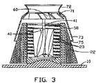
- FIG. 3 is a cross-sectional view of the liquid-cooled heat sink assembly taken along line III—III of FIG. 2 ;
- FIG. 4 is an isometric view of a conventional liquid-cooled heat sink assembly.
- a liquid-cooled heat sink assembly for cooling down an electronic component in accordance with the present invention comprises a base 10 , a main body 20 , a first fan 40 , a second fan 60 , a plugging plate 50 and a shell 70 .
- the base 10 is substantially a flat plate, which is attached onto the electronic component and which supports the main body 20 .
- heat generated by the electronic component concentrates on a central portion thereof, therefore an arched protrusion 11 is formed on a central portion of the base 10 for promoting efficient heat transfer.
- the main body 20 comprises a central, hollow cylindrical core portion (not labeled), and a plurality of curved fins 22 extending radially outwardly from the core portion.
- the core portion has top and bottom surfaces (not labeled).
- a central chamber 21 is defined in the core portion, for receiving liquid coolant.
- the top surface defines a shallow, circular cutout (not labeled) in communication with the central chamber 21 .
- the cutout thus provides a step 24 having a height equal to a thickness of the plugging plate 50 .
- the liquid coolant is added into the central chamber 21 via the cutout.
- An area of each fin 22 progressively increases from the top surface to the bottom surface of the core portion.
- Adjacent fins 22 are substantially parallel to each other, such that the fins 22 have a generally spiraled configuration with a central axis at a center of the main body 20 .
- the main body 20 is generally frustum-shaped, and the fins 22 form a plurality of curved air-guide channels for facilitating airflow.
- a bottom surface of the main body 20 defines a pair of opposite arched concavities (not labeled), for fittingly attaching the main body 20 onto the arched protrusion 11 of the base 10 .
- a plurality of fins 23 (shown in FIG. 3 ) is provided on an inside wall of the core portion in the chamber 21 in helical formation, for facilitating transfer of heat to the fins 22 of the main body 20 .
- the plurality of fins 23 can be replaced by a single helical fin.
- the plurality of fins 23 can be arranged parallel to each other.
- the first fan 40 is received in the central chamber 21 , for agitating the liquid coolant to transfer heat to the inside wall of the core portion.
- the plugging plate 50 is circular, and has a size substantially equal to a size of the cutout of the core portion.
- a hole 51 is defined in a middle of the plugging plate 50 .
- the plugging plate 50 is received on the step 24 , for sealing the central chamber 21 of the core portion.
- the second fan 60 is positioned over the main body 20 . An axle 41 of the first fan 40 is received through the hole 51 of the plugging plate 50 and engaged with the second fan 60 .
- the shell 70 is generally frustum-shaped and hollow to conform with the shape of an upper portion of the main body 20 .
- the shell 70 is also slightly larger than said upper portion, for covering said upper portion.
- the shell 70 comprises an upper portion 72 , a lower portion 73 , and a neck portion 71 interconnecting the upper and lower portions 72 , 73 .
- the upper portion 72 defines an upper opening 74
- the lower portion 73 defines a lower opening 75 .
- a diameter of the lower opening 75 is greater than that of the upper opening 74 .
- a largest diameter of the neck portion 71 is greater than a diameter of the upper opening 74 .
- the neck portion 71 is sized to receive the second fan 60 therein, for forced convection of air through the air-guide channels of the main body 20 from the top surface to the bottom surface.
- a height of the lower portion 73 is substantially less than that of the main body 20 . Accordingly, when the shell 70 is attached on the main body 20 , lower portions of the fins 22 are exposed to the ambient environment for dissipation of air from the air-guide channels thereto.
- the base 10 is attached onto a surface of the electronic component.
- the base 10 transfers heat from the electronic component to the liquid coolant in the central chamber 21 .
- the liquid coolant absorbs the heat and transfers the heat to the fins 23 of the chamber 21 under driving force of the first fan 40 .
- the heat is subsequently conducted to the fins 22 of the main body 20 .
- the heat is dissipated from the fins 22 to air in the air-guide channels and also directly to the ambient environment.
- Under driving force of the second fan 60 air in the air-guide channels is conveyed to the ambient environment. Because the first fan 40 and the second fan 60 are connected to each other, they can be driven by a same single motor. In an alternative embodiment, the first and second fans 40 , 60 can be separately fixed to the main body 20 and be driven by separate motors.
- the first fan 40 can be replaced by other agitating means such as a pug mill, a crutcher or a screw paddle which can suitably agitate the liquid coolant.
Abstract
Description
Claims (20)
Applications Claiming Priority (2)
| Application Number | Priority Date | Filing Date | Title |
|---|---|---|---|
| TW092121877A TWI229583B (en) | 2003-08-03 | 2003-08-03 | Liquid-cooled heat sink device |
| TW92121877 | 2003-08-03 |
Publications (2)
| Publication Number | Publication Date |
|---|---|
| US20050024830A1 US20050024830A1 (en) | 2005-02-03 |
| US7224585B2 true US7224585B2 (en) | 2007-05-29 |
Family
ID=34102251
Family Applications (1)
| Application Number | Title | Priority Date | Filing Date |
|---|---|---|---|
| US10/900,898 Expired - Fee Related US7224585B2 (en) | 2003-08-03 | 2004-07-27 | Liquid-cooled heat sink assembly |
Country Status (2)
| Country | Link |
|---|---|
| US (1) | US7224585B2 (en) |
| TW (1) | TWI229583B (en) |
Cited By (10)
| Publication number | Priority date | Publication date | Assignee | Title |
|---|---|---|---|---|
| US20060278375A1 (en) * | 2005-06-10 | 2006-12-14 | Hon Hai Precision Industry Co., Ltd. | Heat sink apparatus with operating fluid in base thereof |
| US20090266521A1 (en) * | 2008-04-28 | 2009-10-29 | Fu Zhun Precision Industry (Shen Zhen) Co., Ltd. | Heat dissipation device |
| US20090301694A1 (en) * | 2008-06-04 | 2009-12-10 | Fu Zhun Precision Industry (Shen Zhen) Co., Ltd. | Heat dissipation device |
| US20100025021A1 (en) * | 2008-08-04 | 2010-02-04 | Hao Wang | Heat dissipation utilizing flow of refrigerant |
| US20100025015A1 (en) * | 2008-08-04 | 2010-02-04 | Hao Wang | Dissipation utilizing flow of refrigerant |
| US20130213615A1 (en) * | 2012-02-20 | 2013-08-22 | Foxconn Technology Co., Ltd. | Heat dissipation device with convection driven impeller |
| US8863821B2 (en) | 2011-04-18 | 2014-10-21 | Empire Technology Development Llc | Dissipation utilizing flow of refrigerant |
| US10010811B2 (en) | 2013-05-28 | 2018-07-03 | Empire Technology Development Llc | Evaporation-condensation systems and methods for their manufacture and use |
| US10065130B2 (en) | 2013-05-28 | 2018-09-04 | Empire Technology Development Llc | Thin film systems and methods for using same |
| US11347284B2 (en) * | 2020-08-12 | 2022-05-31 | Dongguan Bingdian Intelligent Science & Technology Co., Ltd. | Water cooling radiator with a detachable water pump and a built-in fan |
Families Citing this family (15)
| Publication number | Priority date | Publication date | Assignee | Title |
|---|---|---|---|---|
| US8932227B2 (en) * | 2000-07-28 | 2015-01-13 | Lawrence A. Lynn | System and method for CO2 and oximetry integration |
| CN2727964Y (en) * | 2004-09-17 | 2005-09-21 | 鸿富锦精密工业(深圳)有限公司 | Radiator |
| US7278468B2 (en) * | 2005-10-04 | 2007-10-09 | Delphi Technologies, Inc. | Heat sink with multiple coolant inlets |
| US20080135216A1 (en) * | 2006-12-07 | 2008-06-12 | Chunbo Zhang | Miniature actuator integration for liquid cooling |
| US7667969B2 (en) * | 2007-03-16 | 2010-02-23 | International Business Machines Corporation | Pump structures integral to a fluid filled heat transfer apparatus |
| US20080236794A1 (en) * | 2007-03-27 | 2008-10-02 | Dk Innovations Inc. | Heat-removal device |
| TWI394520B (en) * | 2008-06-06 | 2013-04-21 | Foxconn Tech Co Ltd | Heat dissipation device |
| TWI421671B (en) * | 2008-06-27 | 2014-01-01 | Foxconn Tech Co Ltd | Heat dissipation device |
| DK2259310T3 (en) * | 2009-06-05 | 2020-06-22 | Siemens Gamesa Renewable Energy As | Integrated heat exchanger |
| WO2014175975A1 (en) * | 2013-04-26 | 2014-10-30 | CoolChip Technologies, Inc. | Kinetic heat sink with stationary fins |
| DE102016222376B3 (en) * | 2016-11-15 | 2018-02-15 | Zf Friedrichshafen Ag | Electronic module and method for producing the same |
| KR101972669B1 (en) * | 2017-11-21 | 2019-04-25 | 잘만테크 주식회사 | Water pump of water-cooling type cooler for electronic parts |
| CN107829983B (en) * | 2017-12-04 | 2023-10-20 | 南京磁谷科技有限公司 | Self-operated air conditioning cooling system of magnetic suspension fan |
| CN110621138A (en) * | 2018-06-20 | 2019-12-27 | 鸿富锦精密工业(武汉)有限公司 | Liquid cooling heat radiator and electronic device using same |
| CN114194403B (en) * | 2022-01-25 | 2023-06-02 | 广东汇天航空航天科技有限公司 | Heat radiation structure of driving device and aircraft |
Citations (15)
| Publication number | Priority date | Publication date | Assignee | Title |
|---|---|---|---|---|
| US5285347A (en) | 1990-07-02 | 1994-02-08 | Digital Equipment Corporation | Hybird cooling system for electronic components |
| US5737923A (en) | 1995-10-17 | 1998-04-14 | Marlow Industries, Inc. | Thermoelectric device with evaporating/condensing heat exchanger |
| CN2371768Y (en) | 1999-04-06 | 2000-03-29 | 陈俊良 | Auxiliary radiation circulation system |
| US20010050164A1 (en) * | 1999-08-18 | 2001-12-13 | Agilent Technologies, Inc. | Cooling apparatus for electronic devices |
| US6336497B1 (en) * | 2000-11-24 | 2002-01-08 | Ching-Bin Lin | Self-recirculated heat dissipating means for cooling central processing unit |
| US6343478B1 (en) | 2000-03-21 | 2002-02-05 | Neng-Chao Chang | Water/air dual cooling arrangement for a CPU |
| US6367542B1 (en) * | 2001-03-27 | 2002-04-09 | Foxconn Precision Components Co., Ltd. | Heat sink assembly with dual fans |
| US6408630B2 (en) | 1999-11-04 | 2002-06-25 | Jose Javier Macias | Computer enclosure cooling unit |
| US6466442B2 (en) * | 2001-01-29 | 2002-10-15 | Ching-Bin Lin | Guidably-recirculated heat dissipating means for cooling central processing unit |
| US6538888B1 (en) * | 2001-09-28 | 2003-03-25 | Intel Corporation | Radial base heatsink |
| US6580609B2 (en) | 2001-05-16 | 2003-06-17 | Cray Inc. | Method and apparatus for cooling electronic components |
| US6578626B1 (en) | 2000-11-21 | 2003-06-17 | Thermal Corp. | Liquid cooled heat exchanger with enhanced flow |
| US6708501B1 (en) * | 2002-12-06 | 2004-03-23 | Nanocoolers, Inc. | Cooling of electronics by electrically conducting fluids |
| US6789610B1 (en) * | 2003-08-28 | 2004-09-14 | Hewlett-Packard Development Company, L.P. | High performance cooling device with vapor chamber |
| US7055581B1 (en) * | 2003-06-24 | 2006-06-06 | Roy Sanjay K | Impeller driven active heat sink |
-
2003
- 2003-08-03 TW TW092121877A patent/TWI229583B/en not_active IP Right Cessation
-
2004
- 2004-07-27 US US10/900,898 patent/US7224585B2/en not_active Expired - Fee Related
Patent Citations (15)
| Publication number | Priority date | Publication date | Assignee | Title |
|---|---|---|---|---|
| US5285347A (en) | 1990-07-02 | 1994-02-08 | Digital Equipment Corporation | Hybird cooling system for electronic components |
| US5737923A (en) | 1995-10-17 | 1998-04-14 | Marlow Industries, Inc. | Thermoelectric device with evaporating/condensing heat exchanger |
| CN2371768Y (en) | 1999-04-06 | 2000-03-29 | 陈俊良 | Auxiliary radiation circulation system |
| US20010050164A1 (en) * | 1999-08-18 | 2001-12-13 | Agilent Technologies, Inc. | Cooling apparatus for electronic devices |
| US6408630B2 (en) | 1999-11-04 | 2002-06-25 | Jose Javier Macias | Computer enclosure cooling unit |
| US6343478B1 (en) | 2000-03-21 | 2002-02-05 | Neng-Chao Chang | Water/air dual cooling arrangement for a CPU |
| US6578626B1 (en) | 2000-11-21 | 2003-06-17 | Thermal Corp. | Liquid cooled heat exchanger with enhanced flow |
| US6336497B1 (en) * | 2000-11-24 | 2002-01-08 | Ching-Bin Lin | Self-recirculated heat dissipating means for cooling central processing unit |
| US6466442B2 (en) * | 2001-01-29 | 2002-10-15 | Ching-Bin Lin | Guidably-recirculated heat dissipating means for cooling central processing unit |
| US6367542B1 (en) * | 2001-03-27 | 2002-04-09 | Foxconn Precision Components Co., Ltd. | Heat sink assembly with dual fans |
| US6580609B2 (en) | 2001-05-16 | 2003-06-17 | Cray Inc. | Method and apparatus for cooling electronic components |
| US6538888B1 (en) * | 2001-09-28 | 2003-03-25 | Intel Corporation | Radial base heatsink |
| US6708501B1 (en) * | 2002-12-06 | 2004-03-23 | Nanocoolers, Inc. | Cooling of electronics by electrically conducting fluids |
| US7055581B1 (en) * | 2003-06-24 | 2006-06-06 | Roy Sanjay K | Impeller driven active heat sink |
| US6789610B1 (en) * | 2003-08-28 | 2004-09-14 | Hewlett-Packard Development Company, L.P. | High performance cooling device with vapor chamber |
Cited By (15)
| Publication number | Priority date | Publication date | Assignee | Title |
|---|---|---|---|---|
| US20060278375A1 (en) * | 2005-06-10 | 2006-12-14 | Hon Hai Precision Industry Co., Ltd. | Heat sink apparatus with operating fluid in base thereof |
| US20090266521A1 (en) * | 2008-04-28 | 2009-10-29 | Fu Zhun Precision Industry (Shen Zhen) Co., Ltd. | Heat dissipation device |
| US8347951B2 (en) * | 2008-04-28 | 2013-01-08 | Fu Zhun Precision Industry (Shen Zhen) Co., Ltd. | Heat dissipation device |
| US8245765B2 (en) * | 2008-06-04 | 2012-08-21 | Fu Zhun Precision Industry (Shen Zhen) Co., Lt. | Heat dissipation device |
| US20090301694A1 (en) * | 2008-06-04 | 2009-12-10 | Fu Zhun Precision Industry (Shen Zhen) Co., Ltd. | Heat dissipation device |
| US20100025021A1 (en) * | 2008-08-04 | 2010-02-04 | Hao Wang | Heat dissipation utilizing flow of refrigerant |
| US20100025015A1 (en) * | 2008-08-04 | 2010-02-04 | Hao Wang | Dissipation utilizing flow of refrigerant |
| US8555953B2 (en) * | 2008-08-04 | 2013-10-15 | Empire Technology Development Llc | Heat dissipation utilizing flow of refrigerant |
| US8944150B2 (en) | 2008-08-04 | 2015-02-03 | Empire Technology Development Llc | Dissipation utilizing flow of refrigerant |
| US8863821B2 (en) | 2011-04-18 | 2014-10-21 | Empire Technology Development Llc | Dissipation utilizing flow of refrigerant |
| US9568253B2 (en) | 2011-04-18 | 2017-02-14 | Empire Technology Development Llc | Dissipation utilizing flow of refrigerant |
| US20130213615A1 (en) * | 2012-02-20 | 2013-08-22 | Foxconn Technology Co., Ltd. | Heat dissipation device with convection driven impeller |
| US10010811B2 (en) | 2013-05-28 | 2018-07-03 | Empire Technology Development Llc | Evaporation-condensation systems and methods for their manufacture and use |
| US10065130B2 (en) | 2013-05-28 | 2018-09-04 | Empire Technology Development Llc | Thin film systems and methods for using same |
| US11347284B2 (en) * | 2020-08-12 | 2022-05-31 | Dongguan Bingdian Intelligent Science & Technology Co., Ltd. | Water cooling radiator with a detachable water pump and a built-in fan |
Also Published As
| Publication number | Publication date |
|---|---|
| TWI229583B (en) | 2005-03-11 |
| US20050024830A1 (en) | 2005-02-03 |
Similar Documents
| Publication | Publication Date | Title |
|---|---|---|
| US7224585B2 (en) | Liquid-cooled heat sink assembly | |
| US6529375B2 (en) | Heat sink unit and electronic apparatus using the same | |
| US7120019B2 (en) | Coaxial air ducts and fans for cooling and electronic component | |
| US6817405B2 (en) | Apparatus having forced fluid cooling and pin-fin heat sink | |
| US6199625B1 (en) | Stackable heat sink for electronic components | |
| US7891411B2 (en) | Heat dissipation device having a fan for dissipating heat generated by at least two electronic components | |
| US6324058B1 (en) | Heat-dissipating apparatus for an integrated circuit device | |
| EP1830403B1 (en) | A heat sink with a centrifugal fan | |
| US6732786B1 (en) | Edge-mounted heat dissipation device having top-and-bottom fan structure | |
| US20050036289A1 (en) | Heat dissipation device | |
| US6501652B2 (en) | Heat sink and information processor using it | |
| US6397926B1 (en) | Heat sink, method manufacturing the same and cooling apparatus using the same | |
| JP2001094023A (en) | Cooler for electronic device | |
| US7589967B2 (en) | Heat dissipation device | |
| US8562291B2 (en) | Heat dissipation device and centrifugal fan thereof | |
| US6479895B1 (en) | High performance air cooled heat sinks used in high density packaging applications | |
| US20050183848A1 (en) | Coolant tray of liquid based cooling device | |
| US20050061479A1 (en) | Radiator with streamline airflow guiding structure | |
| US20080011451A1 (en) | Heat sink for electronic device | |
| US20040140084A1 (en) | Heat dissipating device with forced coolant and air flow | |
| KR20040044705A (en) | Cooling Apparatus, and Electric-Electronic Equipment with the Cooling Apparatus | |
| US20050217824A1 (en) | Cooling element for an electronic device | |
| JP2845833B2 (en) | heatsink | |
| US6826049B2 (en) | Heat sink assembly with fan-driven fluid circulation | |
| US20040165351A1 (en) | [package structure compatible with cooling system] |
Legal Events
| Date | Code | Title | Description |
|---|---|---|---|
| AS | Assignment |
Owner name: HON HAI PRECISION IND. CO., LTD., TAIWAN Free format text: ASSIGNMENT OF ASSIGNORS INTEREST;ASSIGNORS:LEE, TSUNG LUNG;WANG, DONG;HE, LI;AND OTHERS;REEL/FRAME:015636/0756 Effective date: 20040212 |
|
| AS | Assignment |
Owner name: FU ZHUN PRECISION INDUSTRY (SHEN ZHEN) CO., LTD., Free format text: ASSIGNMENT OF ASSIGNORS INTEREST;ASSIGNOR:HON HAI PRECISION INDUSTRY CO., LTD.;REEL/FRAME:018879/0706 Effective date: 20070206 Owner name: FOXCONN TECHNOLOGY CO., LTD., TAIWAN Free format text: ASSIGNMENT OF ASSIGNORS INTEREST;ASSIGNOR:HON HAI PRECISION INDUSTRY CO., LTD.;REEL/FRAME:018879/0706 Effective date: 20070206 |
|
| FPAY | Fee payment |
Year of fee payment: 4 |
|
| REMI | Maintenance fee reminder mailed | ||
| LAPS | Lapse for failure to pay maintenance fees | ||
| STCH | Information on status: patent discontinuation |
Free format text: PATENT EXPIRED DUE TO NONPAYMENT OF MAINTENANCE FEES UNDER 37 CFR 1.362 |
|
| FP | Lapsed due to failure to pay maintenance fee |
Effective date: 20150529 |