US7221202B1 - Delay-locked loop with reduced susceptibility to false lock - Google Patents
Delay-locked loop with reduced susceptibility to false lock Download PDFInfo
- Publication number
- US7221202B1 US7221202B1 US11/201,985 US20198505A US7221202B1 US 7221202 B1 US7221202 B1 US 7221202B1 US 20198505 A US20198505 A US 20198505A US 7221202 B1 US7221202 B1 US 7221202B1
- Authority
- US
- United States
- Prior art keywords
- delay
- signal
- coupled
- feedback
- path
- Prior art date
- Legal status (The legal status is an assumption and is not a legal conclusion. Google has not performed a legal analysis and makes no representation as to the accuracy of the status listed.)
- Active
Links
Images


Classifications
-
- H—ELECTRICITY
- H03—ELECTRONIC CIRCUITRY
- H03L—AUTOMATIC CONTROL, STARTING, SYNCHRONISATION, OR STABILISATION OF GENERATORS OF ELECTRONIC OSCILLATIONS OR PULSES
- H03L7/00—Automatic control of frequency or phase; Synchronisation
- H03L7/06—Automatic control of frequency or phase; Synchronisation using a reference signal applied to a frequency- or phase-locked loop
- H03L7/08—Details of the phase-locked loop
- H03L7/0805—Details of the phase-locked loop the loop being adapted to provide an additional control signal for use outside the loop
-
- H—ELECTRICITY
- H03—ELECTRONIC CIRCUITRY
- H03L—AUTOMATIC CONTROL, STARTING, SYNCHRONISATION, OR STABILISATION OF GENERATORS OF ELECTRONIC OSCILLATIONS OR PULSES
- H03L7/00—Automatic control of frequency or phase; Synchronisation
- H03L7/06—Automatic control of frequency or phase; Synchronisation using a reference signal applied to a frequency- or phase-locked loop
- H03L7/08—Details of the phase-locked loop
- H03L7/081—Details of the phase-locked loop provided with an additional controlled phase shifter
- H03L7/0812—Details of the phase-locked loop provided with an additional controlled phase shifter and where no voltage or current controlled oscillator is used
- H03L7/0816—Details of the phase-locked loop provided with an additional controlled phase shifter and where no voltage or current controlled oscillator is used the controlled phase shifter and the frequency- or phase-detection arrangement being connected to a common input
-
- H—ELECTRICITY
- H03—ELECTRONIC CIRCUITRY
- H03L—AUTOMATIC CONTROL, STARTING, SYNCHRONISATION, OR STABILISATION OF GENERATORS OF ELECTRONIC OSCILLATIONS OR PULSES
- H03L7/00—Automatic control of frequency or phase; Synchronisation
- H03L7/06—Automatic control of frequency or phase; Synchronisation using a reference signal applied to a frequency- or phase-locked loop
- H03L7/08—Details of the phase-locked loop
- H03L7/10—Details of the phase-locked loop for assuring initial synchronisation or for broadening the capture range
Definitions
- This disclosure relates generally to electronic circuits, and in particular but not exclusively, relates to delay-locked loop circuits.
- DLLs Delay-locked loops
- DLLs are widely used in communication integrated circuits to generate finely spaced clock phases, multiply clocks, create zero delay buffers, as well as other uses.
- DLL circuit 100 includes a delay line 105 having multiple delay cells 110 , a phase detector 115 , and a loop filter 120 .
- a delayed clock signal output by delay line 105 is phase locked to a one clock period delay of a reference clock signal input to delay line 105 .
- This phase delayed lock is accomplished using a feedback loop.
- the feedback loops converges to a delay line control voltage that sets the delay through delay line 105 to one full period of the reference clock signal.
- Phase detector 115 drives loop filter 120 , which in turn controls the delay through delay line 105 .
- the inputs to phase detector 115 are the reference clock received by delay line 105 and the delayed clock signal output from delay line 105 .
- Phase detector 115 and loop filter 120 adjust the delay through the delay line 105 until a rising edge of the reference clock and a rising edge of the delayed clock are aligned. This ensures the delay through delay line 105 is one clock period of the reference clock, which in turn provides clock edges that are evenly spaced through a clock cycle.
- the initial delay through delay line 105 (before the negative feed-back takes control) must be well-controlled in order for the loop to converge to the correct state-one clock cycle delay. If the initial delay through delay line 105 is not carefully controlled a false lock condition will occur. As illustrated in FIG. 2 , false lock occurs when the initial delay through delay line 105 is either shorter than half of the reference clock period (false lock window 1 ) or longer than one and a half clock periods (false lock window 2 ).
- the feedback loop speeds up delay line 105 to align the rising edges of the reference clock (edge 0 ) and the delayed edge (edge 2 —an impossible task as delay line 105 has a minimum delay that cannot physically be reduced to zero.
- the feedback loop therefore settles to its shortest delay state (less than half a clock period) producing a gross error.
- the initial delay through delay line 105 occurs in false lock window 2
- the feedback tries to lock delay line 105 to two clock periods instead of one (i.e., attempts to align edge 2 with edge 3 ), which also produces an error with heavily distorted waveforms and ultimately complete failure of DLL 100 .
- edge 2 of the delayed clock should eventually align to edge 1 of the reference clock.
- Conventional DLLs must guarantee that the initial rising edge 2 of the delayed clock does not occur in one of these two false lock windows (e.g., false lock windows 1 and 2 ), else the DLL will fail.
- false lock windows 1 and 2 To avoid false lock windows 1 and 2 during startup, conventional DLLs generally use complex startup circuitry and/or larger more expensive delay cells 110 that more accurately control and constrain the time delay through delay line 105 .
- FIG. 1 is a block diagram illustrating a conventional delay-locked loop (“DLL”).
- DLL delay-locked loop
- FIG. 2 is a timing diagram illustrating a false lock problem with conventional DLLs.
- FIG. 3 is a block diagram illustrating a DLL having reduced susceptibility to false lock, in accordance with an embodiment of the invention.
- FIG. 4 is a timing diagram illustrating reduced susceptibility to false lock of a DLL, in accordance with an embodiment of the invention.
- FIG. 5 is a circuit diagram illustrating a startup circuit of a DLL having reduced susceptibility to false lock, in accordance with an embodiment of the invention.
- FIG. 6 is a flow chart illustrating a process of operation for a DLL having reduced susceptibility to false lock, in accordance with an embodiment of the invention.
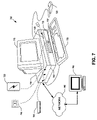
- FIG. 7 illustrates a demonstrative system implemented using an embodiment of the invention.
- Embodiments of a method and apparatus of a delay-locked loop having reduced susceptibility to false lock are described herein.
- numerous specific details are set forth to provide a thorough understanding of the embodiments.
- One skilled in the relevant art will recognize, however, that the techniques described herein can be practiced without one or more of the specific details, or with other methods, components, materials, etc.
- well-known structures, materials, or operations are not shown or described in detail to avoid obscuring certain aspects.
- FIG. 3 is a block diagram illustrating a delay-locked loop (“DLL”) 300 having reduced susceptibility to false lock, in accordance with an embodiment of the invention.
- the illustrated embodiment of DLL 300 includes a delay path 305 including delay cells 310 , a phase detector 315 , a loop filter 320 , an inverter 325 , an input 330 , and an output 335 .
- DLL 300 The components of DLL 300 are interconnected as follows.
- Delay cells 310 are coupled in series to provide a variable delay path for input signal 340 .
- a first one of delay cells 310 is coupled to input 330 to receive input signal 340 .
- Input signal 340 may be a reference signal, clock signal, or otherwise.
- As input signal 340 propagates along delay path 305 it is successively delayed by each delay cell 310 until it is output by a last one of delay cells 310 coupled to output node 335 , as output signal 345 . Accordingly, output signal 345 is a delayed response to input signal 340 .
- Delay cells 310 are delay circuits that can each delay input signal 340 by a variable amount in response to a delay control signal 350 .
- delay cells 310 are voltage controlled delay buffers.
- Delay path 305 may include any number of delay cells 310 .
- delay path 305 includes an even number 2 N of delay cells 310 coupled in series, where N is positive integer.
- a feedback signal 355 is picked off of delay path 305 at a feedback node 360 .
- feedback node 360 is positioned at halfway delay point along delay path 305 .
- feedback node 360 is coupled to the output of the Nth delay cell 310 . Accordingly, in the illustrated embodiment, there are N delay cells 310 before feedback node 360 and N delay cells 310 after feedback node 360 .
- feedback signal 355 is also a delayed response to input signal 340 having a delay approximately equal to half the delay of output signal 345 .
- Inverter 325 is coupled to input 330 to receive input signal 340 and generate inverted signal 370 .
- Phase detector 315 is coupled to the output of inverter 325 to receive inverted signal 370 .
- Phase detector 315 is further coupled to a feedback path 375 , which is coupled to feedback node 360 to deliver feedback signal 355 to phase detector 315 .
- Phase detector 315 receives inverted signal 370 and feedback signal 355 and generates phase information 380 indicative of a phase difference between inverted signal 370 and feedback signal 355 .
- Loop filter 320 is coupled to phase detector 315 to receive phase information 380 . In response to phase information 380 , loop filter 320 generates delay control signal 350 .
- Delay control signal 350 is a sort of error signal for controlling the delay of delay path 305 . In one embodiment, delay control signal 350 is an analog voltage signal.
- Feedback path 375 , phase detector 315 , and loop filter 320 form a negative feedback loop for phase locking output signal 345 to input signal 340 .
- Phase detector 315 and loop filter 320 may collectively be referred to as a feedback circuit 390 . It should be appreciated that a variety of different circuit elements not illustrated may be used to implement the functionality of feedback circuit 390 .
- phase information 380 is a series of positive or negative pulses.
- a positive pulse may indicate that a phase of output signal 345 lags a target phase lock relative to input signal 340
- a negative pulse may indicate that the phase of output signal 345 is leading the target phase lock relative to input signal 340 .
- loop filter 320 integrates these positive and negative pulses to generate delay control signal 350 .
- delayed phase lock is achieved by feeding back phase information at the center of delay path 305 .
- inverter 325 inverts input signal 340 to generate inverter signal 370 , which is then provided to phase detector 315 , instead of input signal 340 itself. This results in locking the phase delay at feedback node 360 (e.g., halfway phase delay of delay path 305 ) to half of the clock period of input signal 340 .
- FIG. 4 is a timing diagram 400 illustrating DLL 300 's reduced susceptibility to the false lock problem, in accordance with an embodiment of the invention.
- FIG. 4 illustrates an example relation between input signal 340 , inverted signal 370 , feedback signal 355 , and output signal 335 .
- edge A of input signal 340 arrives at input 330 .
- inverter 325 inverts edge A of input signal 340 to generate edge A′ of inverted signal 370 .
- input signal 340 has propagated through delay path 305 to feedback node 360 to generate edge B of feedback signal 355 .
- DLL 300 acts to lock to a state where the delay through delay path 305 is half of one period or cycle of input signal 340 , as opposed to a full cycle. As a result, DLL 300 converges to the correct phase delay from any initial delay that is shorter than one period of input signal 340 . This can be seen in FIG. 4 . If the initial phase delay of delay path 305 is less than half of one cycle of input signal 340 , then phase detector 315 generates a negative pulse for phase information 380 that slows down delay path 305 (i.e., increases the delay through delay path 305 ) to align edge B of feedback signal 355 with edge C of inverted signal 370 .
- phase detector 315 If on the other hand, the initial phase delay through delay path 305 is more than half a cycle of input signal 340 (but less than one cycle), then phase detector 315 generates a positive pulse for phase information 380 that speeds up delay path 305 (i.e., reduces the delay through delay path 305 ) to align edge B with edge C. Since in the illustrated embodiment of DLL 300 feedback node 360 is positioned at the halfway delay point along delay path 305 , once edge B of feedback signal 355 is aligned with edge C of inverted signal 370 , then edge D of output signal 345 is aligned with edge E of input signal 340 . Therefore, output signal 345 is a phase locked, one cycle delayed response to input signal 340 .
- operation of feedback circuit 390 may be summarized as follows. If rising edge B of feedback signal 355 occurs during a LOW logic state of input signal 340 , delay control signal 350 is adjusted to increase the delay through delay path 305 . If rising edge B of feedback signal 355 occurs during a HIGH logic state of input signal 340 , delay control signal 350 is adjusted to decrease the delay through delay path 305 .
- DLL 300 will converge to the correct phase delay (e.g., one period delay) as long as the initial delay is less than one period or cycle of input signal 340 . Accordingly, DLL 300 eliminates the first false lock window 1 , illustrated in FIG. 2 . Instead, DLL 300 is susceptible to a single false lock window ranging from 1 to 1.5 cycles of input signal 340 (illustrated as the period between times T 5 and T 6 ). However, avoiding a single false lock window is substantially easier than avoiding two false lock windows. Since there is no minimum requirement for the initial delay of delay path 305 , in one embodiment, the initial delay is set to it's shortest possible delay.
- FIG. 5 is a circuit diagram illustrating a startup circuit 500 for use with DLL 300 , in accordance with an embodiment of the invention.
- Startup circuit 500 is one possible embodiment of a startup circuit for DLL 300 .
- startup circuit 500 is included within loop filter 320 and is coupled to receive the same reset signal as received by loop filter 320 and possibly other subcomponents of DLL 300 .
- Startup circuit 500 includes a transistor (e.g., PMOS transistor) coupled between a voltage rail and a control path 505 for carrying delay control signal 350 .
- PMOS transistor e.g., PMOS transistor
- control path 505 is controlled by loop filter logic of loop filter 320 .
- the transistor Upon assertion of the reset signal, the transistor is enabled or closed circuited, coupling control path 505 to the voltage rail VDD. Coupling control path 505 to the voltage rail VDD places delay cells 310 into their fastest or smallest delay state.
- the loop filter logic takes over control and DLL 300 trends towards its steady state operation or lock state.
- FIG. 5 illustrates a LOW enabled reset signal; however, it should be appreciated startup circuit 500 can be modified to use a HIGH enabled reset signal by coupling an inverter to the base (or gate) of the transistor.
- DLL 300 is illustrated with feedback node 360 placed at the halfway delay point of delay path 305 .
- other embodiments of DLL 300 may include placement of feedback node 360 at various other locations along delay path 305 to generate various different shifted phased locked delays.
- feedback node 360 may be positioned to achieve phased locked delays equal to 0.25, 0.333, 0.5, 0.667, 0.75, 1.75 or otherwise of a cycle of input signal 340 .
- the resolution or granularity for the selection of this alternative phased locked delay is determined by the number of delay cells 310 within delay path 305 .
- FIG. 6 is a flow chart illustrating a process 600 for operation of DLL 300 , in accordance with an embodiment of the invention.
- the order in which some or all of the process blocks appear in each process should not be deemed limiting. Rather, one of ordinary skill in the art having the benefit of the present disclosure will understand that some of the process blocks may be executed in a variety of orders not illustrated or even concurrently.
- operation of DLL 300 is initiated via a reset or power on operation.
- the reset signal is received by loop filter 320 .
- loop filter 320 applies a delay control signal 350 to delay cells 310 , setting delay path 305 to a delay which is outside of the false lock window 2 illustrated in FIG. 4 (process block 610 ).
- the initial value of delay control signal 350 causes delay path 305 to initialize to a minimum delay.
- input signal 340 is received at input 330 and propagates through delay path 305 being successively delayed by each delay cell 310 before reaching feedback node 360 as feedback signal 355 and reaching output 335 as output signal 345 .
- feedback signal 355 is tapped off delay path 305 at feedback node 360 and provided as an input to phase detector 315 .
- input signal 340 is inverted by inverter 325 to generate inverted signal 370 .
- Inverted signal 370 is also provided as an input to phase detector 315 .
- phase detector 315 In a process block 630 , phase detector 315 generates phase information 380 based on the phase difference between inverted signal 370 and feedback signal 355 . Because phase detector 315 is coupled to inverted signal 370 and because feedback signal 355 is tapped off at the halfway delay point of delay path 305 , phase detector 315 measures the phase difference between half of a clock period of input signal 340 and half of the delay of delay path 305 .
- loop filter 320 adjusts the variable delay of delay cells 310 via delay control signal 350 .
- Delay control signal 350 is adjusted based on phase information 380 received from phase detector 315 to achieve a delayed phase lock between input signal 340 and output signal 345 .
- Feedback signal 355 continues to provide negative feedback along feedback path 375 while DLL 300 achieves a delayed phase lock.
- half of delay line 305 is locked to a half period of input signal 340 , which effects a lock between the full delay line 305 and the full period of input signal 340 , but eliminates the first false lock window illustrated in FIG. 2 .
- FIG. 7 illustrates a demonstrative system 700 implemented using an embodiment of the invention.
- the illustrated embodiment of system 700 includes a chassis 710 , a monitor 715 , a mouse 720 (or other pointing device), and a keyboard 725 .
- the illustrated embodiment of chassis 710 further includes a floppy disk drive 730 , a hard disk 735 , a compact disc (“CD”) and/or digital video disc (“DVD”) drive 737 , a power supply (not shown), and a motherboard 740 populated with appropriate integrated circuits including system memory 745 , nonvolatile (“NV”) memory 750 , and one or more processor(s) 755 .
- NV nonvolatile
- NV memory 750 is a flash memory device.
- NV memory 750 includes any one of read only memory (“ROM”), programmable ROM, erasable programmable ROM, electrically erasable programmable ROM, or the like.
- system memory 745 includes random access memory (“RAM”), such as dynamic RAM (“DRAM”), synchronous DRAM, (“SDRAM”), double data rate SDRAM (“DDR SDRAM”) static RAM (“SRAM”), and the like.
- RAM random access memory
- Hard disk 735 represents any storage device for software data, applications, and/or operating systems, but will most typically be a nonvolatile storage device.
- Hard disk 735 may optionally include one or more of an integrated drive electronic (“IDDE”) hard disk, an enhanced IDE (“EIDE”) hard disk, a redundant array of independent disks (“RAID”), a small computer system interface (“SCSI”) hard disk, and the like.
- IDDE integrated drive electronic
- EIDE enhanced IDE
- RAID redundant array of independent disks
- SCSI small computer system interface
- a network interface card (“NIC”) (not shown) is coupled to an expansion slot (not shown) of motherboard 740 .
- the NIC is for connecting system 700 to a network 760 , such as a local area network, wide area network, or the Internet.
- network 760 is further coupled to a remote computer 765 , such that system 700 and remote computer 765 can communicate.
- DLL 300 may be incorporated into processor 755 , as well as, various other integrated circuits (e.g., digital signal processing chips, digital telecommunication circuits, phase recovery circuits, etc.) for generating finely spaced clock phases, multiplying clocks, creating zero delay buffers (e.g., one clock cycle delay buffers), and the like. DLL 300 may be incorporated into NICs of system 700 and/or remote computer 765 for extracting clock signals and/or recovering phase information from transmission signals communicated between the two systems.
- various other integrated circuits e.g., digital signal processing chips, digital telecommunication circuits, phase recovery circuits, etc.
- DLL 300 may be incorporated into NICs of system 700 and/or remote computer 765 for extracting clock signals and/or recovering phase information from transmission signals communicated between the two systems.
- DLL 300 may be generated and compiled for incorporation into processor 755 or other various application specific integrated circuits (“ASICs”).
- behavioral level code describing DLL 300 may be generated using a hardware descriptive language, such as VHDL or Verilog, and stored to a machine-accessible medium (e.g., CD-ROM, hard disk, floppy disk, etc.).
- the behavioral level code can be compiled into register transfer level (“RTL”) code, a netlist, or even a circuit layout and stored to a machine-accessible medium.
- RTL register transfer level
- the behavioral level code, the RTL code, the netlist, and the circuit layout all represent various levels of abstraction to describe embodiments of DLL 300 .
Abstract
Description
Claims (17)
Priority Applications (1)
| Application Number | Priority Date | Filing Date | Title |
|---|---|---|---|
| US11/201,985 US7221202B1 (en) | 2004-09-15 | 2005-08-11 | Delay-locked loop with reduced susceptibility to false lock |
Applications Claiming Priority (2)
| Application Number | Priority Date | Filing Date | Title |
|---|---|---|---|
| US61031804P | 2004-09-15 | 2004-09-15 | |
| US11/201,985 US7221202B1 (en) | 2004-09-15 | 2005-08-11 | Delay-locked loop with reduced susceptibility to false lock |
Publications (1)
| Publication Number | Publication Date |
|---|---|
| US7221202B1 true US7221202B1 (en) | 2007-05-22 |
Family
ID=38049566
Family Applications (1)
| Application Number | Title | Priority Date | Filing Date |
|---|---|---|---|
| US11/201,985 Active US7221202B1 (en) | 2004-09-15 | 2005-08-11 | Delay-locked loop with reduced susceptibility to false lock |
Country Status (1)
| Country | Link |
|---|---|
| US (1) | US7221202B1 (en) |
Cited By (6)
| Publication number | Priority date | Publication date | Assignee | Title |
|---|---|---|---|---|
| US7277357B1 (en) * | 2006-06-05 | 2007-10-02 | Micron Technology, Inc. | Method and apparatus for reducing oscillation in synchronous circuits |
| US20080186781A1 (en) * | 2006-09-29 | 2008-08-07 | Hynix Semiconductor Inc. | Semiconductor memory device |
| US20080303565A1 (en) * | 2007-06-08 | 2008-12-11 | Yen-Hsun Hsu | Dll circuit and related method for avoiding stuck state and harmonic locking utilizing a frequency divider and an inverter |
| US20090189667A1 (en) * | 2008-01-30 | 2009-07-30 | Advantest Corporation | Jitter injection circuit, pattern generator, test apparatus, and electronic device |
| US20120146716A1 (en) * | 2010-12-09 | 2012-06-14 | Taiwan Semiconductor Manufacturing Company, Ltd. | Apparatus for Controlling Slew Rate |
| EP3024141A1 (en) * | 2014-11-24 | 2016-05-25 | Intel Corporation | Interpolator systems and methods |
Citations (4)
| Publication number | Priority date | Publication date | Assignee | Title |
|---|---|---|---|---|
| US5463337A (en) * | 1993-11-30 | 1995-10-31 | At&T Corp. | Delay locked loop based clock synthesizer using a dynamically adjustable number of delay elements therein |
| US6400197B2 (en) * | 2000-01-26 | 2002-06-04 | Via Technologies, Inc. | Delay device having a delay lock loop and method of calibration thereof |
| US6466071B2 (en) * | 2000-04-10 | 2002-10-15 | Samsung Electronics Co., Ltd. | Methods and circuits for correcting a duty-cycle of a signal |
| US20060029175A1 (en) * | 2004-08-05 | 2006-02-09 | Micron Technology, Inc. | Digital frequency locked delay line |
-
2005
- 2005-08-11 US US11/201,985 patent/US7221202B1/en active Active
Patent Citations (4)
| Publication number | Priority date | Publication date | Assignee | Title |
|---|---|---|---|---|
| US5463337A (en) * | 1993-11-30 | 1995-10-31 | At&T Corp. | Delay locked loop based clock synthesizer using a dynamically adjustable number of delay elements therein |
| US6400197B2 (en) * | 2000-01-26 | 2002-06-04 | Via Technologies, Inc. | Delay device having a delay lock loop and method of calibration thereof |
| US6466071B2 (en) * | 2000-04-10 | 2002-10-15 | Samsung Electronics Co., Ltd. | Methods and circuits for correcting a duty-cycle of a signal |
| US20060029175A1 (en) * | 2004-08-05 | 2006-02-09 | Micron Technology, Inc. | Digital frequency locked delay line |
Cited By (16)
| Publication number | Priority date | Publication date | Assignee | Title |
|---|---|---|---|---|
| US20100014377A1 (en) * | 2006-06-05 | 2010-01-21 | Micron Technology, Inc. | Method and apparatus for reducing oscillation in synchronous circuits |
| US20080042702A1 (en) * | 2006-06-05 | 2008-02-21 | Micron Technology, Inc. | Method and apparatus for reducing oscillation in synchronous circuits |
| US8462579B2 (en) | 2006-06-05 | 2013-06-11 | Micron Technology, Inc. | Method and apparatus for reducing oscillation in synchronous circuits |
| US8134886B2 (en) | 2006-06-05 | 2012-03-13 | Micron Technology, Inc. | Method and apparatus for reducing oscillation in synchronous circuits |
| US7277357B1 (en) * | 2006-06-05 | 2007-10-02 | Micron Technology, Inc. | Method and apparatus for reducing oscillation in synchronous circuits |
| US7965580B2 (en) | 2006-06-05 | 2011-06-21 | Micron Technology, Inc. | Method and apparatus for reducing oscillation in synchronous circuits |
| US7596052B2 (en) | 2006-06-05 | 2009-09-29 | Micron Technology Inc. | Method and apparatus for reducing oscillation in synchronous circuits |
| US7495486B2 (en) * | 2006-09-29 | 2009-02-24 | Hynix Semiconductor Inc. | Semiconductor memory device |
| US20080186781A1 (en) * | 2006-09-29 | 2008-08-07 | Hynix Semiconductor Inc. | Semiconductor memory device |
| US20080303565A1 (en) * | 2007-06-08 | 2008-12-11 | Yen-Hsun Hsu | Dll circuit and related method for avoiding stuck state and harmonic locking utilizing a frequency divider and an inverter |
| US7904776B2 (en) * | 2008-01-30 | 2011-03-08 | Advantest Corporation | Jitter injection circuit, pattern generator, test apparatus, and electronic device |
| US20090189667A1 (en) * | 2008-01-30 | 2009-07-30 | Advantest Corporation | Jitter injection circuit, pattern generator, test apparatus, and electronic device |
| US20120146716A1 (en) * | 2010-12-09 | 2012-06-14 | Taiwan Semiconductor Manufacturing Company, Ltd. | Apparatus for Controlling Slew Rate |
| US9236856B2 (en) * | 2010-12-09 | 2016-01-12 | Taiwan Semiconductor Manufactuing Company, Ltd. | Apparatus for controlling slew rate |
| EP3024141A1 (en) * | 2014-11-24 | 2016-05-25 | Intel Corporation | Interpolator systems and methods |
| US9397689B2 (en) | 2014-11-24 | 2016-07-19 | Intel Corporation | Interpolator systems and methods |
Similar Documents
| Publication | Publication Date | Title |
|---|---|---|
| US6836166B2 (en) | Method and system for delay control in synchronization circuits | |
| US6803826B2 (en) | Delay-locked loop circuit and method using a ring oscillator and counter-based delay | |
| US6643219B2 (en) | Synchronous mirror delay with reduced delay line taps | |
| US6975149B2 (en) | Method and circuit for adjusting the timing of output data based on an operational mode of output drivers | |
| US7239575B2 (en) | Delay-locked loop having a pre-shift phase detector | |
| US7098714B2 (en) | Centralizing the lock point of a synchronous circuit | |
| US9001594B2 (en) | Apparatuses and methods for adjusting a path delay of a command path | |
| KR101144519B1 (en) | DLL Phase Detection Using Advanced Phase Equalisation | |
| US20030043615A1 (en) | System and method for skew compensating a clock signal and for capturing a digital signal using the skew compensated clock signal | |
| US9041446B2 (en) | Power savings mode for memory systems | |
| JPH10171774A (en) | Semiconductor integrated circuit | |
| US8917128B1 (en) | Phase determination circuit and delay locked loop circuit using the same | |
| US7221202B1 (en) | Delay-locked loop with reduced susceptibility to false lock | |
| US20100315139A1 (en) | Semiconductor memory device | |
| US7327174B2 (en) | Fast locking mechanism for delay lock loops and phase lock loops | |
| US7274237B2 (en) | Measure control delay and method having latching circuit integral with delay circuit | |
| US9590641B2 (en) | Semiconductor apparatus and regulation circuit thereof | |
| US8786340B1 (en) | Apparatuses, methods, and circuits including a delay circuit having a delay that is adjustable during operation | |
| US20040044918A1 (en) | Measure-controlled delay circuit with reduced playback error |
Legal Events
| Date | Code | Title | Description |
|---|---|---|---|
| AS | Assignment |
Owner name: CYPRESS SEMICONDUCTOR CORPORATION, CALIFORNIA Free format text: ASSIGNMENT OF ASSIGNORS INTEREST;ASSIGNOR:YAYLA, IBRAHIM;REEL/FRAME:016888/0388 Effective date: 20050810 |
|
| STCF | Information on status: patent grant |
Free format text: PATENTED CASE |
|
| FEPP | Fee payment procedure |
Free format text: PAYER NUMBER DE-ASSIGNED (ORIGINAL EVENT CODE: RMPN); ENTITY STATUS OF PATENT OWNER: LARGE ENTITY Free format text: PAYOR NUMBER ASSIGNED (ORIGINAL EVENT CODE: ASPN); ENTITY STATUS OF PATENT OWNER: LARGE ENTITY |
|
| REMI | Maintenance fee reminder mailed | ||
| FPAY | Fee payment |
Year of fee payment: 4 |
|
| SULP | Surcharge for late payment | ||
| FPAY | Fee payment |
Year of fee payment: 8 |
|
| AS | Assignment |
Owner name: MORGAN STANLEY SENIOR FUNDING, INC., NEW YORK Free format text: SECURITY INTEREST;ASSIGNORS:CYPRESS SEMICONDUCTOR CORPORATION;SPANSION LLC;REEL/FRAME:035240/0429 Effective date: 20150312 |
|
| AS | Assignment |
Owner name: SPANSION LLC, CALIFORNIA Free format text: PARTIAL RELEASE OF SECURITY INTEREST IN PATENTS;ASSIGNOR:MORGAN STANLEY SENIOR FUNDING, INC., AS COLLATERAL AGENT;REEL/FRAME:039708/0001 Effective date: 20160811 Owner name: CYPRESS SEMICONDUCTOR CORPORATION, CALIFORNIA Free format text: PARTIAL RELEASE OF SECURITY INTEREST IN PATENTS;ASSIGNOR:MORGAN STANLEY SENIOR FUNDING, INC., AS COLLATERAL AGENT;REEL/FRAME:039708/0001 Effective date: 20160811 |
|
| FEPP | Fee payment procedure |
Free format text: PAYER NUMBER DE-ASSIGNED (ORIGINAL EVENT CODE: RMPN); ENTITY STATUS OF PATENT OWNER: LARGE ENTITY Free format text: PAYOR NUMBER ASSIGNED (ORIGINAL EVENT CODE: ASPN); ENTITY STATUS OF PATENT OWNER: LARGE ENTITY |
|
| AS | Assignment |
Owner name: MONTEREY RESEARCH, LLC, CALIFORNIA Free format text: ASSIGNMENT OF ASSIGNORS INTEREST;ASSIGNOR:CYPRESS SEMICONDUCTOR CORPORATION;REEL/FRAME:040911/0238 Effective date: 20160811 |
|
| MAFP | Maintenance fee payment |
Free format text: PAYMENT OF MAINTENANCE FEE, 12TH YEAR, LARGE ENTITY (ORIGINAL EVENT CODE: M1553); ENTITY STATUS OF PATENT OWNER: LARGE ENTITY Year of fee payment: 12 |
|
| AS | Assignment |
Owner name: MORGAN STANLEY SENIOR FUNDING, INC., NEW YORK Free format text: CORRECTIVE ASSIGNMENT TO CORRECT THE 8647899 PREVIOUSLY RECORDED ON REEL 035240 FRAME 0429. ASSIGNOR(S) HEREBY CONFIRMS THE SECURITY INTERST;ASSIGNORS:CYPRESS SEMICONDUCTOR CORPORATION;SPANSION LLC;REEL/FRAME:058002/0470 Effective date: 20150312 |