US7217221B2 - Method for active engine stop of a hybrid electric vehicle - Google Patents
Method for active engine stop of a hybrid electric vehicle Download PDFInfo
- Publication number
- US7217221B2 US7217221B2 US10/846,144 US84614404A US7217221B2 US 7217221 B2 US7217221 B2 US 7217221B2 US 84614404 A US84614404 A US 84614404A US 7217221 B2 US7217221 B2 US 7217221B2
- Authority
- US
- United States
- Prior art keywords
- engine
- output torque
- engine speed
- electric machine
- speed
- Prior art date
- Legal status (The legal status is an assumption and is not a legal conclusion. Google has not performed a legal analysis and makes no representation as to the accuracy of the status listed.)
- Active, expires
Links
Images


Classifications
-
- F—MECHANICAL ENGINEERING; LIGHTING; HEATING; WEAPONS; BLASTING
- F02—COMBUSTION ENGINES; HOT-GAS OR COMBUSTION-PRODUCT ENGINE PLANTS
- F02D—CONTROLLING COMBUSTION ENGINES
- F02D41/00—Electrical control of supply of combustible mixture or its constituents
- F02D41/02—Circuit arrangements for generating control signals
- F02D41/04—Introducing corrections for particular operating conditions
- F02D41/042—Introducing corrections for particular operating conditions for stopping the engine
-
- B—PERFORMING OPERATIONS; TRANSPORTING
- B60—VEHICLES IN GENERAL
- B60K—ARRANGEMENT OR MOUNTING OF PROPULSION UNITS OR OF TRANSMISSIONS IN VEHICLES; ARRANGEMENT OR MOUNTING OF PLURAL DIVERSE PRIME-MOVERS IN VEHICLES; AUXILIARY DRIVES FOR VEHICLES; INSTRUMENTATION OR DASHBOARDS FOR VEHICLES; ARRANGEMENTS IN CONNECTION WITH COOLING, AIR INTAKE, GAS EXHAUST OR FUEL SUPPLY OF PROPULSION UNITS IN VEHICLES
- B60K6/00—Arrangement or mounting of plural diverse prime-movers for mutual or common propulsion, e.g. hybrid propulsion systems comprising electric motors and internal combustion engines ; Control systems therefor, i.e. systems controlling two or more prime movers, or controlling one of these prime movers and any of the transmission, drive or drive units Informative references: mechanical gearings with secondary electric drive F16H3/72; arrangements for handling mechanical energy structurally associated with the dynamo-electric machine H02K7/00; machines comprising structurally interrelated motor and generator parts H02K51/00; dynamo-electric machines not otherwise provided for in H02K see H02K99/00
- B60K6/20—Arrangement or mounting of plural diverse prime-movers for mutual or common propulsion, e.g. hybrid propulsion systems comprising electric motors and internal combustion engines ; Control systems therefor, i.e. systems controlling two or more prime movers, or controlling one of these prime movers and any of the transmission, drive or drive units Informative references: mechanical gearings with secondary electric drive F16H3/72; arrangements for handling mechanical energy structurally associated with the dynamo-electric machine H02K7/00; machines comprising structurally interrelated motor and generator parts H02K51/00; dynamo-electric machines not otherwise provided for in H02K see H02K99/00 the prime-movers consisting of electric motors and internal combustion engines, e.g. HEVs
- B60K6/42—Arrangement or mounting of plural diverse prime-movers for mutual or common propulsion, e.g. hybrid propulsion systems comprising electric motors and internal combustion engines ; Control systems therefor, i.e. systems controlling two or more prime movers, or controlling one of these prime movers and any of the transmission, drive or drive units Informative references: mechanical gearings with secondary electric drive F16H3/72; arrangements for handling mechanical energy structurally associated with the dynamo-electric machine H02K7/00; machines comprising structurally interrelated motor and generator parts H02K51/00; dynamo-electric machines not otherwise provided for in H02K see H02K99/00 the prime-movers consisting of electric motors and internal combustion engines, e.g. HEVs characterised by the architecture of the hybrid electric vehicle
- B60K6/44—Series-parallel type
- B60K6/445—Differential gearing distribution type
-
- B—PERFORMING OPERATIONS; TRANSPORTING
- B60—VEHICLES IN GENERAL
- B60W—CONJOINT CONTROL OF VEHICLE SUB-UNITS OF DIFFERENT TYPE OR DIFFERENT FUNCTION; CONTROL SYSTEMS SPECIALLY ADAPTED FOR HYBRID VEHICLES; ROAD VEHICLE DRIVE CONTROL SYSTEMS FOR PURPOSES NOT RELATED TO THE CONTROL OF A PARTICULAR SUB-UNIT
- B60W10/00—Conjoint control of vehicle sub-units of different type or different function
- B60W10/04—Conjoint control of vehicle sub-units of different type or different function including control of propulsion units
- B60W10/06—Conjoint control of vehicle sub-units of different type or different function including control of propulsion units including control of combustion engines
-
- B—PERFORMING OPERATIONS; TRANSPORTING
- B60—VEHICLES IN GENERAL
- B60W—CONJOINT CONTROL OF VEHICLE SUB-UNITS OF DIFFERENT TYPE OR DIFFERENT FUNCTION; CONTROL SYSTEMS SPECIALLY ADAPTED FOR HYBRID VEHICLES; ROAD VEHICLE DRIVE CONTROL SYSTEMS FOR PURPOSES NOT RELATED TO THE CONTROL OF A PARTICULAR SUB-UNIT
- B60W10/00—Conjoint control of vehicle sub-units of different type or different function
- B60W10/04—Conjoint control of vehicle sub-units of different type or different function including control of propulsion units
- B60W10/08—Conjoint control of vehicle sub-units of different type or different function including control of propulsion units including control of electric propulsion units, e.g. motors or generators
-
- B—PERFORMING OPERATIONS; TRANSPORTING
- B60—VEHICLES IN GENERAL
- B60W—CONJOINT CONTROL OF VEHICLE SUB-UNITS OF DIFFERENT TYPE OR DIFFERENT FUNCTION; CONTROL SYSTEMS SPECIALLY ADAPTED FOR HYBRID VEHICLES; ROAD VEHICLE DRIVE CONTROL SYSTEMS FOR PURPOSES NOT RELATED TO THE CONTROL OF A PARTICULAR SUB-UNIT
- B60W20/00—Control systems specially adapted for hybrid vehicles
- B60W20/10—Controlling the power contribution of each of the prime movers to meet required power demand
- B60W20/11—Controlling the power contribution of each of the prime movers to meet required power demand using model predictive control [MPC] strategies, i.e. control methods based on models predicting performance
-
- B—PERFORMING OPERATIONS; TRANSPORTING
- B60—VEHICLES IN GENERAL
- B60W—CONJOINT CONTROL OF VEHICLE SUB-UNITS OF DIFFERENT TYPE OR DIFFERENT FUNCTION; CONTROL SYSTEMS SPECIALLY ADAPTED FOR HYBRID VEHICLES; ROAD VEHICLE DRIVE CONTROL SYSTEMS FOR PURPOSES NOT RELATED TO THE CONTROL OF A PARTICULAR SUB-UNIT
- B60W2710/00—Output or target parameters relating to a particular sub-units
- B60W2710/06—Combustion engines, Gas turbines
- B60W2710/0616—Position of fuel or air injector
-
- B—PERFORMING OPERATIONS; TRANSPORTING
- B60—VEHICLES IN GENERAL
- B60W—CONJOINT CONTROL OF VEHICLE SUB-UNITS OF DIFFERENT TYPE OR DIFFERENT FUNCTION; CONTROL SYSTEMS SPECIALLY ADAPTED FOR HYBRID VEHICLES; ROAD VEHICLE DRIVE CONTROL SYSTEMS FOR PURPOSES NOT RELATED TO THE CONTROL OF A PARTICULAR SUB-UNIT
- B60W2710/00—Output or target parameters relating to a particular sub-units
- B60W2710/06—Combustion engines, Gas turbines
- B60W2710/0644—Engine speed
- B60W2710/0661—Speed change rate
-
- F—MECHANICAL ENGINEERING; LIGHTING; HEATING; WEAPONS; BLASTING
- F02—COMBUSTION ENGINES; HOT-GAS OR COMBUSTION-PRODUCT ENGINE PLANTS
- F02D—CONTROLLING COMBUSTION ENGINES
- F02D2250/00—Engine control related to specific problems or objectives
- F02D2250/18—Control of the engine output torque
- F02D2250/24—Control of the engine output torque by using an external load, e.g. a generator
-
- F—MECHANICAL ENGINEERING; LIGHTING; HEATING; WEAPONS; BLASTING
- F02—COMBUSTION ENGINES; HOT-GAS OR COMBUSTION-PRODUCT ENGINE PLANTS
- F02D—CONTROLLING COMBUSTION ENGINES
- F02D31/00—Use of speed-sensing governors to control combustion engines, not otherwise provided for
- F02D31/001—Electric control of rotation speed
-
- Y—GENERAL TAGGING OF NEW TECHNOLOGICAL DEVELOPMENTS; GENERAL TAGGING OF CROSS-SECTIONAL TECHNOLOGIES SPANNING OVER SEVERAL SECTIONS OF THE IPC; TECHNICAL SUBJECTS COVERED BY FORMER USPC CROSS-REFERENCE ART COLLECTIONS [XRACs] AND DIGESTS
- Y02—TECHNOLOGIES OR APPLICATIONS FOR MITIGATION OR ADAPTATION AGAINST CLIMATE CHANGE
- Y02T—CLIMATE CHANGE MITIGATION TECHNOLOGIES RELATED TO TRANSPORTATION
- Y02T10/00—Road transport of goods or passengers
- Y02T10/10—Internal combustion engine [ICE] based vehicles
- Y02T10/40—Engine management systems
-
- Y—GENERAL TAGGING OF NEW TECHNOLOGICAL DEVELOPMENTS; GENERAL TAGGING OF CROSS-SECTIONAL TECHNOLOGIES SPANNING OVER SEVERAL SECTIONS OF THE IPC; TECHNICAL SUBJECTS COVERED BY FORMER USPC CROSS-REFERENCE ART COLLECTIONS [XRACs] AND DIGESTS
- Y02—TECHNOLOGIES OR APPLICATIONS FOR MITIGATION OR ADAPTATION AGAINST CLIMATE CHANGE
- Y02T—CLIMATE CHANGE MITIGATION TECHNOLOGIES RELATED TO TRANSPORTATION
- Y02T10/00—Road transport of goods or passengers
- Y02T10/60—Other road transportation technologies with climate change mitigation effect
- Y02T10/62—Hybrid vehicles
Definitions
- the present invention generally relates to a method of operating a hybrid electric vehicle. More particularly, the method relates to an operating mode for controlling a vehicle powertrain system of a hybrid electric vehicle. Most particularly, the method relates to an operating mode for providing an active engine stop for a hybrid electric vehicle.
- An HEV is a vehicle that has a propulsion system that consists of at least one electric motor or electric machine in combination with at least one other power source.
- the other power source is a gasoline or diesel engine.
- HEVs There are various types of HEVs depending on how the electric motor(s) and other power source(s) are combined with one another in order to provide propulsion for the vehicle, including series, parallel and compound HEVs.
- Series hybrid architectures are generally characterized by an internal combustion engine driving an electric generator which in turn provides electrical power to an electric drivetrain and to an energy storage system, comprising a battery pack.
- the internal combustion engine in a series HEV is not directly mechanically coupled to the drivetrain.
- the electric generator may also operate in a motoring mode to provide a starting function to the internal combustion engine, and the electric drivetrain may recapture vehicle braking energy by also operating in a generator mode to recharge the battery pack.
- Parallel HEV architectures are generally characterized by an internal combustion engine and an electric motor which both have a direct mechanical coupling to the drivetrain.
- the drivetrain conventionally includes a shifting transmission to provide the necessary gear ratios for wide range operation.
- EVT Electrically variable transmissions
- EVTs are known which provide for continuously variable speed ratios by combining features from both series and parallel HEV powertrain architectures.
- EVTs are operable with a direct mechanical path between an internal combustion engine and a final drive unit thus enabling high transmission efficiency and application of lower cost and less massive motor hardware.
- EVTs are also operable with engine operation mechanically independent from the final drive or in various mechanical/electrical split contributions (i.e. input split, output split and compound split configurations) thereby enabling high-torque continuously variable speed ratios, electrically dominated launches, regenerative braking, engine off idling, and two-mode operation.
- the design of the spring damper is constrained by the mechanical packaging of the springs themselves.
- the spring design must meet conflicting criteria.
- the springs must be stiff enough (large spring constant, K) to accept the maximum torque of the engine within their free travel length.
- K large spring constant
- long springs can encounter problems in buckling and are very difficult to package.
- the natural frequency of the system must be significantly lower than the desired idle speed (e.g., by about 1/ ⁇ square root over (2) ⁇ for attenuation), but the high stiffness (K) tends to drive the natural frequency higher (e.g., by ⁇ square root over (K/M) ⁇ ) relationship).
- K small spring constant
- This present invention is a method of providing an active engine stop mode of operation for a vehicle powertrain system comprising an electric machine that is operatively and selectively coupled to an engine and transmission, the system having a system controller for controlling the vehicle powertrain system which is in signal communication with and adapted to provide an output torque command to an engine controller for controlling the output torque of the engine, wherein the electric machine is adapted to provide an output torque to oppose rotation of the engine and provide an active engine stop.
- the method includes the steps of: initiating an active engine stop request; defueling the engine in response to the active engine stop request and maintaining a rotation of the engine and a predetermined engine speed using the electric machine; determining a desired rate of reduction of the engine speed from the predetermined engine speed; and applying an opposing torque using the electric machine to oppose the rotation of the engine and reduce the engine speed consistent with the desired rate of reduction of the engine speed.
- the method is preferably implemented as a computer control algorithm. The method uses the electric motors to actively drive the engine to a stop.
- This method provides the benefit of improving durability of the driveline and improving smoothness during the engine stop by limiting the amount of vibration energy dissipated into the powertrain and vehicle chassis.
- the invention is particularly advantageous in that it may be used with many different types and sizes of engines having many different base idle speeds. It permits a plug and play implementation of different engines without the need to tailor the powertrain system to obtain acceptable noise, vibration and harshness performance.
- FIG. 1 is a mechanical hardware schematic representation of one preferred form of a two-mode, compound-split, electrically variable transmission particularly suited to the implementation of the present invention
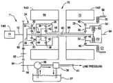
- FIG. 2 is an electrical and mechanical schematic of a preferred system architecture for the hybrid powertrain disclosed herein;
- FIG. 3 is a graphical representation of various regions of operation with respect to input and output speeds of the exemplary electrically variable transmission disclosed herein;
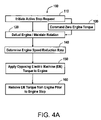
- FIG. 4A is a flow chart illustrating steps of the method of the present invention.
- FIG. 4B is a flow chart illustrating steps associated with block 150 of FIG. 4A ;
- FIG. 5 is a plot of input speed as a function of time associated with the method of the present invention.
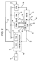
- FIG. 6 is a block diagram of the calculation of output torque of the electric machine according to the method of the invention.
- FIG. 7 is a block diagram of block 225 of FIG. 6 ;
- FIG. 8 is a block diagram of block 235 of FIG. 7 .
- a vehicular powertrain is generally designated 11 .
- the powertrain 11 includes one representative form of a multi-mode, compound-split, electrically variable transmission (EVT) particularly suited for implementing the controls of the present invention and designated generally by the numeral 10 in FIGS. 1 and 2 .
- EVT electrically variable transmission
- the EVT 10 has an input member 12 that may be in the nature of a shaft which may be directly driven by an engine 14 or, as shown in FIG. 2 , a transient torque damper 16 may be incorporated between the output member of the engine 14 and the input member of the EVT 10 .
- the transient torque damper 16 may incorporated, or be employed in conjunction with, a torque transfer device (not shown) to permit selective engagement of the engine 14 with the EVT 10 , but it must be understood that such a torque transfer device is not utilized to change, or control, the mode in which the EVT 10 operates.
- the engine 14 may be a fossil fuel engine, such as a diesel engine which is readily adapted to provide its available power output delivered at a constant number of revolutions per minute (RPM).
- RPM revolutions per minute
- the engine 14 can—after start-up, and during the majority of its input—operate at a constant speed or at a variety of constant speeds in accordance with a desired operating point as may be determined from operator inputs and driving conditions.
- the EVT 10 utilizes three planetary gear subsets 24 , 26 and 28 .
- the first planetary gear subset 24 has an outer gear member 30 , that may generally be designated as the ring gear, which circumscribes an inner gear member 32 , generally designated as the sun gear.
- a plurality of planet gear members 34 are rotatably mounted on a carrier 36 such that each planet gear member 34 meshingly engages both the outer gear member 30 and the inner gear member 32 .
- the second planetary gear subset 26 also has an outer gear member 38 , generally designated as the ring gear, which circumscribes an inner gear member 40 , generally designated as the sun gear.
- a plurality of planet gear members 42 are rotatably mounted on a carrier 44 such that each planet gear 42 meshingly engages both the outer gear member 38 and the inner gear member 40 .
- the third planetary gear subset 28 also has an outer gear member 46 , generally designated as the ring gear, which circumscribes an inner gear member 48 , generally designated as the sun gear.
- a plurality of planet gear members 50 are rotatably mounted on a carrier 52 such that each planet gear 50 meshingly engages both the outer gear member 46 and the inner gear member 48 .
- first and second planetary gear subsets 24 and 26 are compounded in that the inner gear member 32 of the first planetary gear subset 24 is conjoined, as through a hub plate gear 54 , to the outer gear member 38 of the second planetary gear subset 26 .
- the conjoined inner gear member 32 of the first planetary gear subset 24 and the outer gear member 38 of the second planetary gear subset 26 are continuously connected to a first motor/generator 56 , as by a sleeve shaft 58 .
- First electric machine or motor/generator 56 may also be referred to herein variously as motor A or M A .
- the planetary gear subsets 24 and 26 are further compounded in that the carrier 36 of the first planetary gear subset 24 is conjoined, as through a shaft 60 , to the carrier 44 of the second planetary gear subset 26 . As such, carriers 36 and 44 of the first and second planetary gear subsets 24 and 26 , respectively, are conjoined.
- the shaft 60 is also selectively connected to the carrier 52 of the third planetary gear subset 28 , as through a torque transfer device 62 which, as will be hereinafter more fully explained, is employed to assist in the selection of the operational modes of the EVT 10 .
- Torque transfer device 62 may also be referred to herein variously as second clutch, clutch two or C 2 .
- the carrier 52 of the third planetary gear subset 28 is connected directly to the transmission output member 64 .
- the output member 64 may be connected to the vehicular axles (not shown) that may, in turn, terminate in the drive members (also not shown).
- the drive members may be either front or rear wheels of the vehicle on which they are employed, or they may be the drive gear of a track vehicle.
- the inner gear member 40 of the second planetary gear subset 26 is connected to the inner gear member 48 of the third planetary gear subset 28 , as through a sleeve shaft 66 that circumscribes shaft 60 .
- the outer gear member 46 of the third planetary gear subset 28 is selectively connected to ground, represented by the transmission housing 68 , through a torque transfer device 70 .
- Torque transfer device 70 is also employed to assist in the selection of the operational modes of the EVT 10 .
- Torque transfer device 70 may also be referred to herein variously as first clutch, clutch one or C 1 .
- the sleeve shaft 66 is also continuously connected to a second electric machine or motor/generator 72 .
- Second motor/generator 72 may also be referred to herein variously as motor B or M B .
- All the planetary gear subsets 24 , 26 and 28 as well as motor A and motor B ( 56 , 72 ) are coaxially oriented, as about the axially disposed shaft 60 .
- both motors A and B are of an annular configuration which permits them to circumscribe the three planetary gear subsets 24 , 26 and 28 such that the planetary gear subsets 24 , 26 and 28 are disposed radially inwardly of the motors A and B. This configuration assures that the overall envelope—i.e., the circumferential dimension—of the EVT 10 is minimized.
- a drive gear 80 may be presented from the input member 12 .
- the drive gear 80 fixedly connects the input member 12 to the outer gear member 30 of the first planetary gear subset 24 , and the drive gear 80 , therefore, receives power from the engine 14 and/or the motor/generators 56 and/or 72 .
- the drive gear 80 meshingly engages an idler gear 82 which, in turn, meshingly engages a transfer gear 84 that is secured to one end of a shaft 86 .
- the other end of the shaft 86 may be secured to a transmission fluid pump and 88 which is supplied transmission fluid from sump 37 , delivering high pressure fluid to regulator 39 which returns a portion of the fluid to sump 37 and provides regulated line pressure in line 41 .
- the output member 64 receives power through two distinct gear trains within the EVT 10 .
- a first mode, or gear train is selected when the first clutch C 1 is actuated in order to “ground” the outer gear member 46 of the third planetary gear subset 28 .
- a second mode, or gear train is selected when the first clutch C 1 is released and the second clutch C 2 is simultaneously actuated to connect the shaft 60 to the carrier 52 of the third planetary gear subset 28 .
- the EVT 10 is capable of providing a range of output speeds from relatively slow to relatively fast within each mode of operation. This combination of two modes with a slow to fast output speed range in each mode allows the EVT 10 to propel a vehicle from a stationary condition to highway speeds.
- a fixed-ratio state wherein both clutches C 1 and C 2 are simultaneously applied is available for efficient mechanical coupling of the input member to the output member through a fixed gear ratio.
- a neutral state wherein both clutches C 1 and C 2 are simultaneously released is available for mechanically decoupling the output member from the transmission.
- the EVT 10 is capable to provide synchronized shifts between the modes wherein slip speed across both clutches C 1 and C 2 is substantially zero. Additional details regarding operation of the exemplary EVT can be found in commonly assigned U.S. Pat. No. 5,931,757, the contents of which are incorporated herein by reference.
- Engine 14 is preferably a diesel engine and electronically controlled by engine control module (with the) 23 as illustrated in FIG. 2 .
- ECM 23 is a conventional microprocessor based diesel engine controller comprising such common elements as microprocessor, read only memory ROM, random access memory RAM, electrically programmable read only memory EPROM, high speed clock, analog to digital (A/D) and digital to analog (D/A) circuitry, and input/output circuitry and devices (I/O) and appropriate signal conditioning and buffer circuitry.
- ECM 23 functions to acquire data from a variety of sensors and control a variety of actuators, respectively, of the engine 14 over a plurality of discrete lines. For simplicity, ECM 23 is shown generally in bi-directional interface with engine 14 via aggregate line 35 .
- ECM 23 Among the various parameters that may be sensed by ECM 23 are oil sump and engine coolant temperatures, engine speed (Ne), turbo pressure, and ambient air temperature and pressure.
- Various actuators that may be controlled by the ECM 23 include fuel injectors, fan controllers, engine preheaters including glow plugs and grid-type intake air heaters.
- ECM preferably provides for well-known torque-based controls for engine 14 in response to a torque command Te_cmd provided by the EVT control system.
- Such engines electronics, controls and quantities are generally well known to those skilled in the art and further detailed exposition thereof is not required herein
- the EVT 10 selectively receives power from the engine 14 .
- the EVT also receives power from an electric energy storage device or system 20 (ESS), such as one or more batteries in battery pack module (BPM) 21 .
- ESS electric energy storage device or system 20
- BPM 21 battery pack module
- ESS electric energy storage device or system 20
- BPM 21 is preferably a parallel array of battery packs, each of which comprises a plurality of batteries.
- the term battery generally refers to any secondary or rechargeable battery, but those comprising lead/acid, nickel/metal hydride (Ni/MH), or Li/ion or polymer cells are preferred.
- Other electric energy storage devices that have the ability to store electric power through charging and dispense electric power through discharging, such as super capacitors or ultracapacitors, may be used in place of, or in combination with, the batteries without altering the concepts of the present invention.
- the BPM 21 is high voltage DC (e.g., about 650 V in an exemplary embodiment) coupled to dual power inverter module (DPIM) 19 via DC lines 27 . Current is transferable to or from the BPM 21 in accordance with whether the BPM 21 is being charged or discharged.
- DPIM dual power inverter module
- BPM 21 also comprises a conventional microprocessor based controller comprising such common elements as microprocessor, read only memory ROM, random access memory RAM, electrically programmable read only memory EPROM, high speed clock, analog to digital (A/D) and digital to analog (D/A) circuitry, and input/output circuitry and devices (I/O), temperature sensors and appropriate signal conditioning and buffer circuitry necessary to monitor the state of the battery and transmit this information to other portions of the control system for use in the overall control of the vehicle, such as VCM 15 and TCM 17 .
- a conventional microprocessor based controller comprising such common elements as microprocessor, read only memory ROM, random access memory RAM, electrically programmable read only memory EPROM, high speed clock, analog to digital (A/D) and digital to analog (D/A) circuitry, and input/output circuitry and devices (I/O), temperature sensors and appropriate signal conditioning and buffer circuitry necessary to monitor the state of the battery and transmit this information to other portions of the control system for use in the overall control of the vehicle,
- SOC state of charge
- DPIM 19 includes a pair of power inverters and respective motor controllers configured to receive motor control commands and control inverter states therefrom for providing motor drive or regeneration functionality.
- Motor controllers are microprocessor based controllers comprising such common elements as microprocessor, read only memory ROM, random access memory RAM, electrically programmable read only memory EPROM, high speed clock, analog to digital (A/D) and digital to analog (D/A) circuitry, and input/output circuitry and devices (I/O) and appropriate signal conditioning and buffer circuitry.
- the respective inverter receives current from the DC lines and provides AC current to the respective motor over high voltage phase lines 29 and 31 .
- the respective inverter receives AC current from the motor over high voltage phase lines 29 and 31 and provides current to the DC lines 27 .
- the net DC current provided to or from the inverters determines the charge or discharge operating mode of the BPM 21 .
- M A and M B are three-phase AC machines and the inverters comprise complementary three-phase power electronics.
- Individual motor speed signals Na and Nb for M A and M B are also derived by the DPIM 19 from the motor phase information or in conventional rotation sensors.
- Such motors, electronics, controls and quantities are generally well known to those skilled in the art and further detailed exposition thereof is not required herein.
- System controller 43 is a microprocessor based controller comprising such common elements as microprocessor, read only memory ROM random access memory RAM, electrically programmable read only memory EPROM, high speed clock, analog to digital (A/D) and digital to analog (D/A) circuitry, digital signal processor (DSP), and input/output circuitry and devices (I/O) and appropriate signal conditioning and buffer circuitry.
- system controller 43 comprises a pair of microprocessor based controllers designated as vehicle control module (VCM) 15 and transmission control module (TCM) 17 .
- VCM vehicle control module
- TCM transmission control module
- VCM and TCM may provide, for example, a variety of control and diagnostic functions related to EVT and vehicle chassis including, for example, engine torque commands, input speed control, and output torque control in coordination with regenerative braking, anti-lock braking and traction control.
- system controller 43 functions to directly acquire data from a variety of sensors and directly control a variety of actuators, respectively, of the EVT over a plurality of discrete lines.
- system controller 43 is shown generally in bidirectional interface with EVT via aggregate line 33 .
- System controller 43 may also incorporate any number of discrete signal and sensor lines for signal communication between system controller 43 and any number of the other controllers, sensors or other devices.
- system controller 43 is in signal communication with ECM 23 via signal line 45 for transmitting an discrete engine on/off signal in addition to communication between these devices via communication bus 25 .
- system controller 43 receives frequency signals from rotation sensors for processing into input member 12 speed Ni and output member 64 speed No for use in the control of EVT 10 .
- System controller 43 may also receive and process pressure signals from pressure switches (not separately illustrated) for monitoring clutch C 1 and C 2 application chamber pressures. Alternatively, pressure transducers for wide range pressure monitoring may be employed. PWM and/or binary control signals are provided by system controller to EVT 10 for controlling fill and drain of clutches C 1 and C 2 for application and release thereof.
- system controller 43 may receive transmission fluid sump 37 temperature data, such as from conventional thermocouple input (not separately illustrated) to derive sump temperature Ts and provide a PWM signal which may be derived from input speed Ni and sump temperature Ts for control of line pressure via regulator 39 .
- PWM signal which may be derived from input speed Ni and sump temperature Ts for control of line pressure via regulator 39 .
- Fill and drain of clutches C 1 and C 2 are effectuated by way of solenoid controlled spool valves responsive to PWM and binary control signals as alluded to above.
- line pressure regulator 39 may be of a solenoid controlled variety for establishing regulated line pressure in accordance with the described PWM signal. Such line pressure controls are generally well known to those skilled in the art.
- Clutch slip speeds across clutches C 1 and C 2 are derived from output speed No, M A speed Na and M B speed Nb; specifically, C 1 slip is a function of No and Nb, whereas C 2 slip is a function of No, Na and Nb.
- UI user interface
- System controller 43 determines a torque command Te_cmd and provides it to ECM 23 .
- Torque command Te_cmd is representative of the EVT torque contribution desired from the engine as determined by the system controller.
- the various modules described communicate via controller area network (CAN) bus 25 .
- CAN bus 25 allows for communication of control parameters and commands between the various modules.
- the specific communication protocol utilized will be application specific. For example the preferred protocol for heavy duty applications is the Society of Automotive Engineers standard J1939.
- the CAN bus and appropriate protocols provide for robust messaging and multi-controller interfacing between the system controller, ECM, DPIM, BPIM and other controllers such as antilock brake and traction controllers.
- a plot of output speed No along the horizontal axis versus input speed Ni across the vertical axis for the EVT 10 is illustrated.
- Synchronous operation that is the input speed and output speed relationships whereat both clutch C 1 and C 2 are operating simultaneously with substantially zero slip speed thereacross is represented by line 91 .
- it represents the input and output speed relationships substantially whereat synchronous shifting from between modes can occur or whereat direct mechanical coupling from input to output can be affected by simultaneous application of both clutches C 1 and C 2 , also known as fixed-ratio.
- Line 91 may be variously referred to herein as synchronous line, shift ratio line or fixed-ratio line.
- region of operation 93 is generally preferred for the operation of the EVT in MODE 1, it is not meant to imply that MODE 2 operation of the EVT cannot or does not occur therein. Generally, however, it is preferred to operate in MODE 1 in region 93 because MODE 1 preferably employs gearsets and motor hardware particularly well suited in various aspects (e.g., mass, size, cost, inertial capabilities, etc.) to the high launch torques of region 93 .
- region of operation 95 is generally preferred for the operation of the EVT in MODE 2, it is not meant to imply that MODE 1 operation of the EVT cannot or does not occur therein.
- MODE 2 it is preferred to operate in MODE 2 in region 95 because MODE 2 preferably employs gearsets and motor hardware particularly well suited in various aspects (e.g., mass, size, cost, inertial capabilities, etc.) to the high speeds of region 95 .
- a shift into MODE 1 is considered a downshift and is associated with a higher gear ratio in accordance with the relationship of Ni/No.
- a shift into MODE 2 is considered an upshift and is associated with a lower gear ratio in accordance with the relationship of Ni/No.
- Output speed, No, and input speed, Ni are preferably derived from sensed and filtered signals. Motor speeds Na and Nb are known through sensing, calculated with known coupling constraints of the EVT, or derived through the motor control phase information.
- Input acceleration, Ni_dot is preferably a desired rate of change of transmission input speed determined as taught in commonly assigned and co-pending U.S. Ser. No. 10/686,511 (Attorney Docket Number GP-304140).
- Output speed acceleration, No_dot is preferably determined in accordance with sensed and filtered output speed, No, also as disclosed in commonly assigned and co-pending U.S. Ser. No. 10/686,511 (Attorney Docket Number GP-304140).
- Ncx_dot is representative of the slip acceleration of a clutch “x” used to couple the electric machine to the other elements of vehicle powertrain system in accordance with the present invention.
- the following exemplary coupling constraint equation is known for the EVT described herein for calculating the motor A and motor B output torques:
- the present invention comprises a method 100 of providing an active engine stop mode of operation for a vehicle powertrain system comprising an electric machine that is operatively and selectively coupled to an engine and transmission, the system having a system controller for controlling the vehicle powertrain system which is in signal communication with and adapted to provide an output torque command to an engine controller for controlling the output torque of the engine, wherein the electric machine is adapted to provide an output torque to oppose rotation of the engine and provide an active engine stop, comprising the steps of: initiating 110 an active engine stop request; defueling 120 the engine in response to the active engine stop request and maintaining a rotation of the engine and a predetermined engine speed using the electric machine; determining 140 a desired rate of reduction of the engine speed from the predetermined engine speed; and applying 150 an opposing torque using the electric machine to oppose the rotation of the engine and reduce the engine speed consistent with the desired rate of reduction of the engine speed.
- the active engine stop request also preferably comprises sending 130 an engine output torque command for zero engine output torque. It is believed that method 100 may be implemented either in hardware, such as, for example, using various forms of hardwired logic and computational components, or in software, or in various combinations thereof. However, it is preferred that method 100 comprise a computer control algorithm which may be executed as computer code in one or more computers located in the vehicle, such as found in system controller 43 . Method 100 is described in greater detail below.
- An active engine stop mode of operation is a mode of operation of the vehicle powertrain system, such as vehicle powertrain system 11 , where control actions are applied, preferably by one of the controllers of the vehicle powertrain system, such as system controller 43 , to actively stop the rotation of the engine in response to an active engine stop request.
- This is in contrast to a passive stop of the engine as described above, wherein the rotational energy of the engine is dissipated by frictional losses and the action of the spring damper.
- An active engine stop is characterized by a more rapid rate of reduction of engine speed than occurs with a passive engine stop.
- passive engine stops may take about 1.5–2 seconds and exhibit deceleration rates on the order of about ⁇ 300 to ⁇ 1000 rpm/sec, whereas active engine stops typically may be performed in about 0.5 seconds or less and exhibit deceleration rates on the order of about ⁇ 1200 to ⁇ 4000 rpm/sec.
- Active stops are particularly advantageous in that they permit rapid transition through the engine resonance speed (e.g., about 400 rpm depending on the particular engine, transmission and other factors). Active stops are also advantageous because actual rate of reduction may be actively controlled to a particular and uniform rate, rather than a non-uniform rate that is determined by the system components and which cannot easily be changed.
- the ability to achieve a uniform and controlled rate during the active engine stop also provides design flexibility in that it permits more rapid integration (i.e., a plug and play interchange) of different system components (i.e., different combinations of engines, transmissions, spring dampers, etc.) without the need for extensive characterization of the noise, vibration and harshness (NVH) characteristics of the various combinations of components with respect to the engine stop, particularly the characterization of the NVH performance of these combinations at the resonance speed of the powertrain system.
- NVH noise, vibration and harshness
- An active engine stop mode of operation may be utilized with many types of vehicle powertrain systems, particularly those comprising hybrid electric vehicles.
- Vehicle powertrain systems adapted for an active engine stop mode of operation will generally comprise an electric machine that is operatively and selectively coupled to an engine and transmission, and that is adapted to provide an output torque to oppose rotation of the engine.
- the system will also have a system controller for controlling the vehicle powertrain system which is in signal communication with and adapted to provide an output torque command to an engine controller for controlling the output torque of the engine. As shown in FIGS.
- vehicle powertrain system such as powertrain system 11
- vehicle powertrain system 11 may comprise a plurality of electric machines that are each operatively and selectively coupled to an engine and transmission through a corresponding clutch, wherein at least one of the plurality of electric machines is adapted to provide an output torque to oppose the rotation of the engine and provide an active engine stop.
- An active engine stop request is an input to the system, perferably a signal input to a controller, such as system controller 43 , indicating that an active stop of the engine is requested.
- a controller such as system controller 43
- all requests to shut off the engine be active engine stop requests. While it is possible and generally preferable to design a powertrain system to implement both passive engine stop requests (i.e., a stop using only a spring damper, frictional losses, and other passive elements) and active requests, such as is illustrated herein with respect to powertrain system 11 , it is believed that the use of active engine stop will be preferred for most engine stop requests.
- the passive engine stop may be used then primarily as a back-up engine stop mechanism in the event that the active engine stop is not available.
- the signal input to controller may be a signal in response to a keyswitch actuation resulting from a “key-off” action by the operator, as is well-known.
- the keyswitch actuation such as a key-off, sends a key-off signal to a controller, such as system controller 43 .
- This key-off signal comprises the active engine stop request.
- the input to the controller comprising the active engine stop request may comprise a signal determined automatically by the controller, such as system controller 43 , or another controller in the system, in response to a predetermined engine stop parameter or condition.
- a predetermined engine stop parameter is any parameter or condition associated with the vehicle powertrain system for which an active stop of the engine may be associated or scheduled.
- an active engine stop may be associated with one or more system parameters, such as vehicle speed or transmission output speed while in a silent mode or condition of operation, or in response to a signal input from a switch associated with the vehicle condition, such as a switched signal that is adapted to provide a door open indication, which may also be associated with a silent mode of operation.
- a switch associated with the vehicle condition such as a switched signal that is adapted to provide a door open indication, which may also be associated with a silent mode of operation.
- the step of initiating 110 an active engine stop request may be any action to initiate an active stop request, including all manner of manual actions determined by an operator and automatic actions initiated by one or more controllers to affect an engine stop request.
- initiating 110 may comprise a manual input from an operator, such as the actuation of a keyswitch by the operator, such as a keyswitch actuation in response to a “key-off” action by the operator.
- initiating 110 of the active engine stop request may comprise an automatic or programmed input of an engine stop parameter to a controller, such as system controller 43 , wherein the controller is adapted to initiate an active engine stop automatically in response to the value or condition of the engine stop parameter.
- a controller such as system controller 43
- the controller is adapted to initiate an active engine stop automatically in response to the value or condition of the engine stop parameter.
- the time associated with initiating 110 the active engine stop request is designated as time, t 0 , as indicated by the associated reference line.
- Method 100 also includes a step of defueling 120 the engine in response to the active engine stop request and maintaining a rotation of the engine and a predetermined engine speed using the electric machine.
- Defueling 120 the engine such as engine 14
- Defueling 120 may be accomplished by any of a number of well-known means.
- defueling 120 may be controlled by ECM 23 in response to or in conjunction with a step of sending 130 an engine output torque command, Te_cmd, for zero engine output torque to ECM 23 from system controller 43 over communication bus 25 .
- the system controller may also preferably remove an “engine on” signal over discrete signal line 45 that is adapted to provide an “on/off” signal to engine 14 .
- the control commands associated with defueling 120 and sending 130 an engine output torque command may be performed using any of a number of well-known means including various well-known communication standards and protocols. In the case of powertrain system 11 , such control commands are preferably performed in accordance with Society of Automotive Engineers standard J1939. Referring to FIG. 5 , the time associated with defueling 120 and sending 130 is illustrated generally as time t 1 , as indicated by the associated reference line, as they generally occur nearly simultaneously. However, as a matter of design choice, these steps may also be taken at different times (not shown). It is also generally preferred to perform the step of defueling 120 for a predetermined defueling interval prior to proceeding with subsequent steps of method 100 , excepting the step of sending 130 an engine output torque command for zero engine output torque.
- the predetermined defueling interval is preferably selected to allow any remaining fuel to be consumed and to permit the engine output torque to be reduced to near zero prior to implementing subsequent control actions. In this way, the output torque required from the electric machine in subsequent steps is also reduced.
- the predetermined defueling interval was about 100 ms, but will vary according to factors associated with the engine, fueling system and other elements of the vehicle powertrain system. Referring to FIG. 5 , the predetermined defueling interval is illustrated as the time interval between t 1 and t 2 .
- the controller In conjunction with the command for zero engine output torque, the controller, such as system controller 43 , also issues the necessary torque control commands to at least one of the electric machines to assume the control of the rotation of the engine.
- this assumption of control has been described herein as maintaining a rotation of the engine and a predetermined engine speed using the electric machine.
- the predetermined engine speed may be any desired rotational speed of the engine, however, it is preferred that the predetermined engine speed be the rotational speed of the engine corresponding to the time of initiating 110 the active engine stop request.
- the electric machine torque or torques necessary to maintain the predetermined engine speeed or input speed, Ni may be calculated in the manner described herein.
- the measured input speed of the system is available at all times to the controller which is adapted to implement method 100 , such as system controller 43 .
- the electric machine torque may be calculated using the relationship described herein.
- the values associated with the vehicle dynamic parameters used for this calculation include: Ni_dot equal to zero in order to maintain the current input speed, Ni, (engine speed) at time t 0 ; the value of Ti being selected or set to a value generally equal to or slightly greater than the value of the frictional losses associated with engine which are generally well characterized and may comprise a calibration value (i.e., sufficient to maintain the engine rotation); the value of No_dot may be any suitable value, but is preferably selected as the current value at time t 0 ; and the value of Nc1_dot may be any suitable value, however, it is preferred that the value be selected as zero, such that clutch C 1 may be rapidly engaged in response to a subsequent restart of the engine and engagement of powertrain system 11 . It should
- method 100 also includes a step of determining 140 a desired rate of reduction of the engine speed from the predetermined engine speed.
- This desired rate of reduction of engine speed or engine deceleration rate may be determined in any of a number of well-known methods.
- Determining 140 may, for example, include establishing a fixed deceleration as a calibration value or values. These values could be preselected as a function of engine speed (e.g., at time t 0 ). However, it is preferred that determining 140 comprise calculating an engine speed reduction trajectory for the engine.
- the engine speed reduction trajectory may be calculated in accordance with a relationship comprising:
- method 100 also includes a step of applying 150 an opposing torque using the electric machine to oppose the rotation of the engine and reduce the engine speed consistent with the desired rate of reduction of the engine speed.
- the step of applying 150 an opposing torque may be performed by the further steps including: determining 152 an electric machine output torque command necessary to obtain the engine speed trajectory as a function of a plurality of vehicle dynamic parameters; and controlling 154 the electric machine output torque using the electric machine output torque command.
- the step of determining 152 the electric machine output torque command necessary to obtain the engine speed trajectory as a function of a plurality of vehicle dynamic parameters is illustrated for a powertrain system, such as powertrain system 11 , having two electric machines M A and M B , as described herein.
- the electric machine torques may be determined using the appropriate coupling equation, such as Equation 1, as illustrated by block 210 .
- the outputs of block 210 are the respective electric machine motor torques Ta and Tb, which are preferably applied as respective motor commands Ta_cmd and Tb_cmd.
- the step of controlling 154 preferably comprises open loop control of M A and M B using Ta_cmd and Tb_cmd, respectively.
- Ta_cmd and Tb_cmd are illustrated in FIG. 6 as Ta OL 215 and Tb OL 220 , respectively.
- the coupling equation or equations will of course vary depending on the configuration of the powertrain system and its elements.
- Method 100 and the step of determining 140 the opposing motor torque also may comprise utilization of a closed loop correction of the electric machine torque as a function of the error between the input speed determined in accordance with the speed reduction trajectory and the actual or measured input speed.
- this comprises the further steps of: calculating 156 an engine speed trajectory error using the engine speed from the speed trajectory and an actual engine speed; determining 158 an electric machine output torque command correction based on the trajectory error; and applying 159 the electric machine output torque command correction to the electric machine output torque command.
- the step of calculating 156 an engine speed trajectory error using the engine speed from the speed reduction trajectory and an actual engine speed is illustrated with regard to block 225 of FIG.
- Ni E RR is the difference between the actual input speed, Ni M EAS , and the desired input speed associated with the input speed reduction trajectory, Ni, as illustrated by summing node 265 .
- This engine speed trajectory error is preferably calculated in conjunction with each control loop of controller. Referring to FIGS. 6–8 and the step of determining 158 an electric machine output torque command correction based on the trajectory error, the engine speed trajectory error and may be fed to a proportional integral (PI) control portion 270 of the controller, such as system controller 43 , wherein the error may be integrated using well-known methods for performing such control.
- PI proportional integral
- This input speed trajectory error term may be used to determine an electric machine output torque command correction for each of the electric machines of the system, and as illustrated with respect to powertrain system 11 in block 235 as corrections for Ta_cmd and Tb_cmd, which are illustrated as Ta CL 240 and Tb CL 245 , respectively.
- closed loop term, CL 230 may be applied to empirically determined calibrations which are adapted to relate the magnitude of the input speed error to the respective incremental motor torque or torques necessary to reduce, and preferably to zero out the error. These are illustrated in FIG.
- the closed loop corrections for M A and M B in the form of Ta CL 240 and Tb CL 245 may be applied to Ta OL 215 and Tb OL 220 , respectively as illustrated to obtain corrected and more accurate values for Ta_cmd and Tb_cmd, which are illustrated respectively, as Ta 255 and Tb 260 .
- method 100 may also include a step of removing 160 the opposing torque of the electric machine at an engine speed greater than zero engine speed.
- This step is intended to eliminate the possibility of overshoot in the control and imparting a negative speed to or counter-rotating the engine.
- This step may be performed by removing the electric machine output torques from the engine below a predetermined engine speed threshold and allowing the engine rotation to come to a stop at a slower rate based on the frictional torque losses associated with the engine, as illustrated in FIG. 5 with respect to time t 5 .
- the predetermined engine speed threshold is preferably less than a resonance speed of the vehicle powertrain system, as described herein.
Abstract
Description
where
- Ta is motor A speed;
- Tb is motor B speed;
- Ti is EVT input speed;
- Ni_dot is EVT input acceleration;
- No_dot is EVT output acceleration;
- Nc1_dot is the C1 slip acceleration;
- Kn is a 2×4 matrix of parametric values determined by the hardware gear and shaft interconnections and estimated hardware inertias applicable to the current drive range and represents what is commonly referred to as the plant model.
where:
- Ni(t0) is the input speed of the transmission and the engine output speed at time t0; and
- tSR1 is the duration of a predetermined speed reduction interval.
Since the target engine speed at the end of the engine deceleration trajectory is preferably zero, the speed reduction is simply the negative of the difference of the predetermined engine speed and zero, which is simply the negative of the predetermined engine speed. If the target speed at the end of the trajectory is selected to be a speed other than the zero, determining 140 would comprise taking the difference of the predetermined speed and the target speed at the end of the deceleration trajectory. The predetermined speed reduction interval is preferably a fixed interval which may be stored as a calibration value in the controller, such assystem controller 43. However, predetermined speed reduction interval may also be calculated if desired. Where the active engine stop is in response to a key-off action of an operator, the time during which the other elements of the system, including the controller and the electric machines, may be used to assist with the active engine stop is limited, as they are also in the process of being shutdown in accordance with various shutdown parameters associated with them. In the case of the electric machines, this is typically a fixed time interval (e.g., an interval determined by the manufacturer of the machine and its associated controls), such as, for example, about 2 seconds, whereafter the electric machine or machines receive a stop command. Therefore, it is desirable that the active engine stop be performed within an interval during which the system components used in the control, such as the controller and the electric machine, are available for use in conjunction withmethod 100. In one embodiment, the predetermined speed reduction interval was about 0.5 seconds. Referring toFIG. 5 , the predetermined speed reduction interval is illustrated as the time interval between times t2 and t4.
Claims (26)
Priority Applications (3)
| Application Number | Priority Date | Filing Date | Title |
|---|---|---|---|
| US10/846,144 US7217221B2 (en) | 2004-05-14 | 2004-05-14 | Method for active engine stop of a hybrid electric vehicle |
| DE102005021801.6A DE102005021801B4 (en) | 2004-05-14 | 2005-05-11 | A method of controlling an active engine stop of a hybrid electric vehicle |
| CNB2005101098629A CN100383000C (en) | 2004-05-14 | 2005-05-13 | Method for active engine stop of a hybrid electric vehicle |
Applications Claiming Priority (1)
| Application Number | Priority Date | Filing Date | Title |
|---|---|---|---|
| US10/846,144 US7217221B2 (en) | 2004-05-14 | 2004-05-14 | Method for active engine stop of a hybrid electric vehicle |
Publications (2)
| Publication Number | Publication Date |
|---|---|
| US20050255968A1 US20050255968A1 (en) | 2005-11-17 |
| US7217221B2 true US7217221B2 (en) | 2007-05-15 |
Family
ID=35310131
Family Applications (1)
| Application Number | Title | Priority Date | Filing Date |
|---|---|---|---|
| US10/846,144 Active 2024-12-29 US7217221B2 (en) | 2004-05-14 | 2004-05-14 | Method for active engine stop of a hybrid electric vehicle |
Country Status (3)
| Country | Link |
|---|---|
| US (1) | US7217221B2 (en) |
| CN (1) | CN100383000C (en) |
| DE (1) | DE102005021801B4 (en) |
Cited By (22)
| Publication number | Priority date | Publication date | Assignee | Title |
|---|---|---|---|---|
| US20070084653A1 (en) * | 2005-10-18 | 2007-04-19 | Eaton Corporation | Method and system for shutting down an engine in a hybrid vehicle |
| US20080054647A1 (en) * | 2006-08-30 | 2008-03-06 | General Electric Company | System and Method for Emergency Shutdown of an Internal Combustion Engine |
| US20090075773A1 (en) * | 2007-09-13 | 2009-03-19 | Martini Ryan D | Method and apparatus to detect a mode-gear mismatch during operation of an electro-mechanical transmission |
| US20090131216A1 (en) * | 2005-10-26 | 2009-05-21 | Toyota Jidosha Kabushiki Kaisha | Controller for vehicle drive device |
| US20100137097A1 (en) * | 2008-12-02 | 2010-06-03 | Kia Motors Corporation | Method of controlling hybrid vehicle |
| US20100179739A1 (en) * | 2007-07-06 | 2010-07-15 | Renault S.A.S. | Power-assistance device for a vehicle |
| US20100286858A1 (en) * | 2008-03-06 | 2010-11-11 | Nissan Motor Co., Ltd. | Control apparatus for hybrid vehicle |
| US20120215392A1 (en) * | 2009-12-11 | 2012-08-23 | Toyota Jidosha Kabushiki Kaisha | Vehicle and control method thereof |
| US8313402B2 (en) | 2010-06-18 | 2012-11-20 | Hyundai Motor Company | Transmission for hybrid electric vehicle |
| US20130152894A1 (en) * | 2011-12-14 | 2013-06-20 | Ford Global Technologies, Llc | Stop/start engine glow plug heater control |
| US8475312B2 (en) | 2010-06-18 | 2013-07-02 | Hyundai Motor Company | Transmission for hybrid electric vehicle |
| US8579750B2 (en) | 2010-06-18 | 2013-11-12 | Hyundai Motor Company | Transmission for hybrid electric vehicle |
| US8663066B2 (en) * | 2010-04-02 | 2014-03-04 | Ford Global Technologies, Llc | Powertrain driveline warm-up system and method |
| US20140074333A1 (en) * | 2011-02-17 | 2014-03-13 | Hitoshi Ohkuma | Control device for hybrid vehicle |
| US8672789B2 (en) | 2010-06-18 | 2014-03-18 | Hyundai Motor Company | Transmission for hybrid electric vehicle |
| US8840498B2 (en) | 2010-06-07 | 2014-09-23 | Hyundai Motor Company | Transmission for hybrid electric vehicle |
| US20140343775A1 (en) * | 2013-05-17 | 2014-11-20 | Toyota Jidosha Kabushiki Kaisha | Hybrid vehicle and control method for hybrid vehicle |
| US8894540B2 (en) | 2012-09-13 | 2014-11-25 | Ford Global Technologies, Llc | Method and apparatus for controlling engine shutdown in hybrid vehicles |
| US9248831B2 (en) * | 2012-03-26 | 2016-02-02 | Toyota Jidosha Kabushiki Kaisha | Drive control device for hybrid vehicle |
| US9599977B1 (en) * | 2013-03-14 | 2017-03-21 | Cirrus Logic, Inc. | Programmable system architecture for power controllers including thread execution responsive to power train event |
| US10245971B2 (en) * | 2017-03-06 | 2019-04-02 | Gates Corporation | Motor-generator system |
| US10343508B2 (en) * | 2016-12-20 | 2019-07-09 | Toyota Jidosha Kabushiki Kaisha | Vehicle control apparatus |
Families Citing this family (170)
| Publication number | Priority date | Publication date | Assignee | Title |
|---|---|---|---|---|
| US8010263B2 (en) * | 2006-03-22 | 2011-08-30 | GM Global Technology Operations LLC | Method and apparatus for multivariate active driveline damping |
| US8091667B2 (en) * | 2006-06-07 | 2012-01-10 | GM Global Technology Operations LLC | Method for operating a hybrid electric powertrain based on predictive effects upon an electrical energy storage device |
| JP4643525B2 (en) * | 2006-08-31 | 2011-03-02 | トヨタ自動車株式会社 | Engine system |
| US7987934B2 (en) | 2007-03-29 | 2011-08-02 | GM Global Technology Operations LLC | Method for controlling engine speed in a hybrid electric vehicle |
| US7999496B2 (en) * | 2007-05-03 | 2011-08-16 | GM Global Technology Operations LLC | Method and apparatus to determine rotational position of an electrical machine |
| US7996145B2 (en) | 2007-05-03 | 2011-08-09 | GM Global Technology Operations LLC | Method and apparatus to control engine restart for a hybrid powertrain system |
| US7991519B2 (en) | 2007-05-14 | 2011-08-02 | GM Global Technology Operations LLC | Control architecture and method to evaluate engine off operation of a hybrid powertrain system operating in a continuously variable mode |
| US8390240B2 (en) | 2007-08-06 | 2013-03-05 | GM Global Technology Operations LLC | Absolute position sensor for field-oriented control of an induction motor |
| US7983823B2 (en) | 2007-09-11 | 2011-07-19 | GM Global Technology Operations LLC | Method and control architecture for selection of optimal engine input torque for a powertrain system |
| US8265813B2 (en) * | 2007-09-11 | 2012-09-11 | GM Global Technology Operations LLC | Method and control architecture for optimization of engine fuel-cutoff selection and engine input torque for a hybrid powertrain system |
| US7988591B2 (en) * | 2007-09-11 | 2011-08-02 | GM Global Technology Operations LLC | Control architecture and method for one-dimensional optimization of input torque and motor torque in fixed gear for a hybrid powertrain system |
| US8027771B2 (en) * | 2007-09-13 | 2011-09-27 | GM Global Technology Operations LLC | Method and apparatus to monitor an output speed sensor during operation of an electro-mechanical transmission |
| US7867135B2 (en) | 2007-09-26 | 2011-01-11 | GM Global Technology Operations LLC | Electro-mechanical transmission control system |
| US8062170B2 (en) * | 2007-09-28 | 2011-11-22 | GM Global Technology Operations LLC | Thermal protection of an electric drive system |
| FR2922176B1 (en) * | 2007-10-10 | 2010-02-26 | Renault Sas | METHOD AND SYSTEM FOR STOPPING A MOTORPOWER GROUP EQUIPPED WITH AN INFINITELY VARIABLE TRANSMISSION |
| US8234048B2 (en) | 2007-10-19 | 2012-07-31 | GM Global Technology Operations LLC | Method and system for inhibiting operation in a commanded operating range state for a transmission of a powertrain system |
| US9140337B2 (en) | 2007-10-23 | 2015-09-22 | GM Global Technology Operations LLC | Method for model based clutch control and torque estimation |
| US8060267B2 (en) | 2007-10-23 | 2011-11-15 | GM Global Technology Operations LLC | Method for controlling power flow within a powertrain system |
| US8187145B2 (en) | 2007-10-25 | 2012-05-29 | GM Global Technology Operations LLC | Method and apparatus for clutch torque control in mode and fixed gear for a hybrid powertrain system |
| US8296027B2 (en) | 2007-10-25 | 2012-10-23 | GM Global Technology Operations LLC | Method and apparatus to control off-going clutch torque during torque phase for a hybrid powertrain system |
| US8265821B2 (en) | 2007-10-25 | 2012-09-11 | GM Global Technology Operations LLC | Method for determining a voltage level across an electric circuit of a powertrain |
| US8335623B2 (en) | 2007-10-25 | 2012-12-18 | GM Global Technology Operations LLC | Method and apparatus for remediation of and recovery from a clutch slip event in a hybrid powertrain system |
| US8118122B2 (en) | 2007-10-25 | 2012-02-21 | GM Global Technology Operations LLC | Method and system for monitoring signal integrity in a distributed controls system |
| US8303463B2 (en) | 2007-10-26 | 2012-11-06 | GM Global Technology Operations LLC | Method and apparatus to control clutch fill pressure in an electro-mechanical transmission |
| US8548703B2 (en) | 2007-10-26 | 2013-10-01 | GM Global Technology Operations LLC | Method and apparatus to determine clutch slippage in an electro-mechanical transmission |
| US7985154B2 (en) | 2007-10-26 | 2011-07-26 | GM Global Technology Operations LLC | Method and apparatus to control hydraulic pressure for component lubrication in an electro-mechanical transmission |
| US9097337B2 (en) | 2007-10-26 | 2015-08-04 | GM Global Technology Operations LLC | Method and apparatus to control hydraulic line pressure in an electro-mechanical transmission |
| US8167773B2 (en) | 2007-10-26 | 2012-05-01 | GM Global Technology Operations LLC | Method and apparatus to control motor cooling in an electro-mechanical transmission |
| US8204702B2 (en) | 2007-10-26 | 2012-06-19 | GM Global Technology Operations LLC | Method for estimating battery life in a hybrid powertrain |
| US8560191B2 (en) | 2007-10-26 | 2013-10-15 | GM Global Technology Operations LLC | Method and apparatus to control clutch pressures in an electro-mechanical transmission |
| US8406945B2 (en) | 2007-10-26 | 2013-03-26 | GM Global Technology Operations LLC | Method and apparatus to control logic valves for hydraulic flow control in an electro-mechanical transmission |
| US8099219B2 (en) | 2007-10-27 | 2012-01-17 | GM Global Technology Operations LLC | Method and apparatus for securing an operating range state mechanical transmission |
| US8244426B2 (en) | 2007-10-27 | 2012-08-14 | GM Global Technology Operations LLC | Method and apparatus for monitoring processor integrity in a distributed control module system for a powertrain system |
| US8062174B2 (en) | 2007-10-27 | 2011-11-22 | GM Global Technology Operations LLC | Method and apparatus to control clutch stroke volume in an electro-mechanical transmission |
| US8428816B2 (en) | 2007-10-27 | 2013-04-23 | GM Global Technology Operations LLC | Method and apparatus for monitoring software and signal integrity in a distributed control module system for a powertrain system |
| US8170762B2 (en) | 2007-10-29 | 2012-05-01 | GM Global Technology Operations LLC | Method and apparatus to control operation of a hydraulic pump for an electro-mechanical transmission |
| US8209098B2 (en) | 2007-10-29 | 2012-06-26 | GM Global Technology Operations LLC | Method and apparatus for monitoring a transmission range selector in a hybrid powertrain transmission |
| US8489293B2 (en) | 2007-10-29 | 2013-07-16 | GM Global Technology Operations LLC | Method and apparatus to control input speed profile during inertia speed phase for a hybrid powertrain system |
| US8282526B2 (en) | 2007-10-29 | 2012-10-09 | GM Global Technology Operations LLC | Method and apparatus to create a pseudo torque phase during oncoming clutch engagement to prevent clutch slip for a hybrid powertrain system |
| US8290681B2 (en) | 2007-10-29 | 2012-10-16 | GM Global Technology Operations LLC | Method and apparatus to produce a smooth input speed profile in mode for a hybrid powertrain system |
| US8112194B2 (en) | 2007-10-29 | 2012-02-07 | GM Global Technology Operations LLC | Method and apparatus for monitoring regenerative operation in a hybrid powertrain system |
| US8095254B2 (en) | 2007-10-29 | 2012-01-10 | GM Global Technology Operations LLC | Method for determining a power constraint for controlling a powertrain system |
| US8078371B2 (en) | 2007-10-31 | 2011-12-13 | GM Global Technology Operations LLC | Method and apparatus to monitor output of an electro-mechanical transmission |
| US8035324B2 (en) | 2007-11-01 | 2011-10-11 | GM Global Technology Operations LLC | Method for determining an achievable torque operating region for a transmission |
| US8556011B2 (en) | 2007-11-01 | 2013-10-15 | GM Global Technology Operations LLC | Prediction strategy for thermal management and protection of power electronic hardware |
| US8145375B2 (en) | 2007-11-01 | 2012-03-27 | GM Global Technology Operations LLC | System constraints method of determining minimum and maximum torque limits for an electro-mechanical powertrain system |
| US8073602B2 (en) | 2007-11-01 | 2011-12-06 | GM Global Technology Operations LLC | System constraints method of controlling operation of an electro-mechanical transmission with an additional constraint range |
| US7977896B2 (en) | 2007-11-01 | 2011-07-12 | GM Global Technology Operations LLC | Method of determining torque limit with motor torque and battery power constraints |
| US8121767B2 (en) | 2007-11-02 | 2012-02-21 | GM Global Technology Operations LLC | Predicted and immediate output torque control architecture for a hybrid powertrain system |
| US8825320B2 (en) | 2007-11-02 | 2014-09-02 | GM Global Technology Operations LLC | Method and apparatus for developing a deceleration-based synchronous shift schedule |
| US8847426B2 (en) | 2007-11-02 | 2014-09-30 | GM Global Technology Operations LLC | Method for managing electric power in a powertrain system |
| US8131437B2 (en) | 2007-11-02 | 2012-03-06 | GM Global Technology Operations LLC | Method for operating a powertrain system to transition between engine states |
| US8224539B2 (en) | 2007-11-02 | 2012-07-17 | GM Global Technology Operations LLC | Method for altitude-compensated transmission shift scheduling |
| US8200403B2 (en) | 2007-11-02 | 2012-06-12 | GM Global Technology Operations LLC | Method for controlling input torque provided to a transmission |
| US8121765B2 (en) | 2007-11-02 | 2012-02-21 | GM Global Technology Operations LLC | System constraints method of controlling operation of an electro-mechanical transmission with two external input torque ranges |
| US8133151B2 (en) | 2007-11-02 | 2012-03-13 | GM Global Technology Operations LLC | System constraints method of controlling operation of an electro-mechanical transmission with an additional constraint |
| US8170764B2 (en) | 2007-11-02 | 2012-05-01 | GM Global Technology Operations LLC | Method and apparatus to reprofile input speed during speed during speed phase during constrained conditions for a hybrid powertrain system |
| US8585540B2 (en) | 2007-11-02 | 2013-11-19 | GM Global Technology Operations LLC | Control system for engine torque management for a hybrid powertrain system |
| US8287426B2 (en) | 2007-11-02 | 2012-10-16 | GM Global Technology Operations LLC | Method for controlling voltage within a powertrain system |
| US8135526B2 (en) | 2007-11-03 | 2012-03-13 | GM Global Technology Operations LLC | Method for controlling regenerative braking and friction braking |
| US8260511B2 (en) | 2007-11-03 | 2012-09-04 | GM Global Technology Operations LLC | Method for stabilization of mode and fixed gear for a hybrid powertrain system |
| US8868252B2 (en) | 2007-11-03 | 2014-10-21 | GM Global Technology Operations LLC | Control architecture and method for two-dimensional optimization of input speed and input power including search windowing |
| US8285431B2 (en) | 2007-11-03 | 2012-10-09 | GM Global Technology Operations LLC | Optimal selection of hybrid range state and/or input speed with a blended braking system in a hybrid electric vehicle |
| US8224514B2 (en) | 2007-11-03 | 2012-07-17 | GM Global Technology Operations LLC | Creation and depletion of short term power capability in a hybrid electric vehicle |
| US8068966B2 (en) | 2007-11-03 | 2011-11-29 | GM Global Technology Operations LLC | Method for monitoring an auxiliary pump for a hybrid powertrain |
| US8296021B2 (en) | 2007-11-03 | 2012-10-23 | GM Global Technology Operations LLC | Method for determining constraints on input torque in a hybrid transmission |
| US8155814B2 (en) | 2007-11-03 | 2012-04-10 | GM Global Technology Operations LLC | Method of operating a vehicle utilizing regenerative braking |
| US8002667B2 (en) | 2007-11-03 | 2011-08-23 | GM Global Technology Operations LLC | Method for determining input speed acceleration limits in a hybrid transmission |
| US8010247B2 (en) | 2007-11-03 | 2011-08-30 | GM Global Technology Operations LLC | Method for operating an engine in a hybrid powertrain system |
| US8204664B2 (en) | 2007-11-03 | 2012-06-19 | GM Global Technology Operations LLC | Method for controlling regenerative braking in a vehicle |
| US8406970B2 (en) | 2007-11-03 | 2013-03-26 | GM Global Technology Operations LLC | Method for stabilization of optimal input speed in mode for a hybrid powertrain system |
| US8200383B2 (en) | 2007-11-04 | 2012-06-12 | GM Global Technology Operations LLC | Method for controlling a powertrain system based upon torque machine temperature |
| US8000866B2 (en) | 2007-11-04 | 2011-08-16 | GM Global Technology Operations LLC | Engine control system for torque management in a hybrid powertrain system |
| US8121766B2 (en) | 2007-11-04 | 2012-02-21 | GM Global Technology Operations LLC | Method for operating an internal combustion engine to transmit power to a driveline |
| US8092339B2 (en) | 2007-11-04 | 2012-01-10 | GM Global Technology Operations LLC | Method and apparatus to prioritize input acceleration and clutch synchronization performance in neutral for a hybrid powertrain system |
| US9008926B2 (en) | 2007-11-04 | 2015-04-14 | GM Global Technology Operations LLC | Control of engine torque during upshift and downshift torque phase for a hybrid powertrain system |
| US8002665B2 (en) | 2007-11-04 | 2011-08-23 | GM Global Technology Operations LLC | Method for controlling power actuators in a hybrid powertrain system |
| US7988594B2 (en) | 2007-11-04 | 2011-08-02 | GM Global Technology Operations LLC | Method for load-based stabilization of mode and fixed gear operation of a hybrid powertrain system |
| US8126624B2 (en) | 2007-11-04 | 2012-02-28 | GM Global Technology Operations LLC | Method for selection of optimal mode and gear and input speed for preselect or tap up/down operation |
| US8112206B2 (en) | 2007-11-04 | 2012-02-07 | GM Global Technology Operations LLC | Method for controlling a powertrain system based upon energy storage device temperature |
| US8112192B2 (en) | 2007-11-04 | 2012-02-07 | GM Global Technology Operations LLC | Method for managing electric power within a powertrain system |
| US8414449B2 (en) | 2007-11-04 | 2013-04-09 | GM Global Technology Operations LLC | Method and apparatus to perform asynchronous shifts with oncoming slipping clutch torque for a hybrid powertrain system |
| US8095282B2 (en) | 2007-11-04 | 2012-01-10 | GM Global Technology Operations LLC | Method and apparatus for soft costing input speed and output speed in mode and fixed gear as function of system temperatures for cold and hot operation for a hybrid powertrain system |
| US8138703B2 (en) | 2007-11-04 | 2012-03-20 | GM Global Technology Operations LLC | Method and apparatus for constraining output torque in a hybrid powertrain system |
| US8214114B2 (en) | 2007-11-04 | 2012-07-03 | GM Global Technology Operations LLC | Control of engine torque for traction and stability control events for a hybrid powertrain system |
| US8897975B2 (en) | 2007-11-04 | 2014-11-25 | GM Global Technology Operations LLC | Method for controlling a powertrain system based on penalty costs |
| US8374758B2 (en) | 2007-11-04 | 2013-02-12 | GM Global Technology Operations LLC | Method for developing a trip cost structure to understand input speed trip for a hybrid powertrain system |
| US8067908B2 (en) | 2007-11-04 | 2011-11-29 | GM Global Technology Operations LLC | Method for electric power boosting in a powertrain system |
| US8594867B2 (en) | 2007-11-04 | 2013-11-26 | GM Global Technology Operations LLC | System architecture for a blended braking system in a hybrid powertrain system |
| US8630776B2 (en) | 2007-11-04 | 2014-01-14 | GM Global Technology Operations LLC | Method for controlling an engine of a hybrid powertrain in a fuel enrichment mode |
| US8135532B2 (en) | 2007-11-04 | 2012-03-13 | GM Global Technology Operations LLC | Method for controlling output power of an energy storage device in a powertrain system |
| US8396634B2 (en) | 2007-11-04 | 2013-03-12 | GM Global Technology Operations LLC | Method and apparatus for maximum and minimum output torque performance by selection of hybrid range state and input speed for a hybrid powertrain system |
| US8221285B2 (en) | 2007-11-04 | 2012-07-17 | GM Global Technology Operations LLC | Method and apparatus to offload offgoing clutch torque with asynchronous oncoming clutch torque, engine and motor torque for a hybrid powertrain system |
| US8818660B2 (en) | 2007-11-04 | 2014-08-26 | GM Global Technology Operations LLC | Method for managing lash in a driveline |
| US8118903B2 (en) | 2007-11-04 | 2012-02-21 | GM Global Technology Operations LLC | Method for preferential selection of modes and gear with inertia effects for a hybrid powertrain system |
| US8145397B2 (en) | 2007-11-04 | 2012-03-27 | GM Global Technology Operations LLC | Optimal selection of blended braking capacity for a hybrid electric vehicle |
| US8346449B2 (en) | 2007-11-04 | 2013-01-01 | GM Global Technology Operations LLC | Method and apparatus to provide necessary output torque reserve by selection of hybrid range state and input speed for a hybrid powertrain system |
| US8504259B2 (en) | 2007-11-04 | 2013-08-06 | GM Global Technology Operations LLC | Method for determining inertia effects for a hybrid powertrain system |
| US8204656B2 (en) | 2007-11-04 | 2012-06-19 | GM Global Technology Operations LLC | Control architecture for output torque shaping and motor torque determination for a hybrid powertrain system |
| US8214120B2 (en) | 2007-11-04 | 2012-07-03 | GM Global Technology Operations LLC | Method to manage a high voltage system in a hybrid powertrain system |
| US8248023B2 (en) | 2007-11-04 | 2012-08-21 | GM Global Technology Operations LLC | Method of externally charging a powertrain |
| US8098041B2 (en) | 2007-11-04 | 2012-01-17 | GM Global Technology Operations LLC | Method of charging a powertrain |
| US8214093B2 (en) | 2007-11-04 | 2012-07-03 | GM Global Technology Operations LLC | Method and apparatus to prioritize transmission output torque and input acceleration for a hybrid powertrain system |
| US8079933B2 (en) | 2007-11-04 | 2011-12-20 | GM Global Technology Operations LLC | Method and apparatus to control engine torque to peak main pressure for a hybrid powertrain system |
| US8494732B2 (en) | 2007-11-04 | 2013-07-23 | GM Global Technology Operations LLC | Method for determining a preferred engine operation in a hybrid powertrain system during blended braking |
| US8229633B2 (en) | 2007-11-05 | 2012-07-24 | GM Global Technology Operations LLC | Method for operating a powertrain system to control engine stabilization |
| US8448731B2 (en) | 2007-11-05 | 2013-05-28 | GM Global Technology Operations LLC | Method and apparatus for determination of fast actuating engine torque for a hybrid powertrain system |
| US8155815B2 (en) | 2007-11-05 | 2012-04-10 | Gm Global Technology Operation Llc | Method and apparatus for securing output torque in a distributed control module system for a powertrain system |
| US8321100B2 (en) | 2007-11-05 | 2012-11-27 | GM Global Technology Operations LLC | Method and apparatus for dynamic output torque limiting for a hybrid powertrain system |
| US8285432B2 (en) | 2007-11-05 | 2012-10-09 | GM Global Technology Operations LLC | Method and apparatus for developing a control architecture for coordinating shift execution and engine torque control |
| US8135519B2 (en) | 2007-11-05 | 2012-03-13 | GM Global Technology Operations LLC | Method and apparatus to determine a preferred output torque for operating a hybrid transmission in a fixed gear operating range state |
| US8121768B2 (en) | 2007-11-05 | 2012-02-21 | GM Global Technology Operations LLC | Method for controlling a hybrid powertrain system based upon hydraulic pressure and clutch reactive torque capacity |
| US8099204B2 (en) | 2007-11-05 | 2012-01-17 | GM Global Technology Operatons LLC | Method for controlling electric boost in a hybrid powertrain |
| US8249766B2 (en) | 2007-11-05 | 2012-08-21 | GM Global Technology Operations LLC | Method of determining output torque limits of a hybrid transmission operating in a fixed gear operating range state |
| US8165777B2 (en) | 2007-11-05 | 2012-04-24 | GM Global Technology Operations LLC | Method to compensate for transmission spin loss for a hybrid powertrain system |
| US8112207B2 (en) | 2007-11-05 | 2012-02-07 | GM Global Technology Operations LLC | Method and apparatus to determine a preferred output torque for operating a hybrid transmission in a continuously variable mode |
| US8073601B2 (en) | 2007-11-05 | 2011-12-06 | GM Global Technology Operations LLC | Method for preferential selection of mode and gear and input speed based on multiple engine state fueling costs for a hybrid powertrain system |
| US8070647B2 (en) | 2007-11-05 | 2011-12-06 | GM Global Technology Operations LLC | Method and apparatus for adapting engine operation in a hybrid powertrain system for active driveline damping |
| US8285462B2 (en) | 2007-11-05 | 2012-10-09 | GM Global Technology Operations LLC | Method and apparatus to determine a preferred output torque in mode and fixed gear operation with clutch torque constraints for a hybrid powertrain system |
| US8160761B2 (en) | 2007-11-05 | 2012-04-17 | GM Global Technology Operations LLC | Method for predicting an operator torque request of a hybrid powertrain system |
| US8219303B2 (en) | 2007-11-05 | 2012-07-10 | GM Global Technology Operations LLC | Method for operating an internal combustion engine for a hybrid powertrain system |
| US8281885B2 (en) | 2007-11-06 | 2012-10-09 | GM Global Technology Operations LLC | Method and apparatus to monitor rotational speeds in an electro-mechanical transmission |
| US8179127B2 (en) | 2007-11-06 | 2012-05-15 | GM Global Technology Operations LLC | Method and apparatus to monitor position of a rotatable shaft |
| US8277363B2 (en) | 2007-11-07 | 2012-10-02 | GM Global Technology Operations LLC | Method and apparatus to control temperature of an exhaust aftertreatment system for a hybrid powertrain |
| US8073610B2 (en) | 2007-11-07 | 2011-12-06 | GM Global Technology Operations LLC | Method and apparatus to control warm-up of an exhaust aftertreatment system for a hybrid powertrain |
| US8224544B2 (en) * | 2007-11-07 | 2012-07-17 | GM Global Technology Operations LLC | Method and apparatus to control launch of a vehicle having an electro-mechanical transmission |
| US8433486B2 (en) | 2007-11-07 | 2013-04-30 | GM Global Technology Operations LLC | Method and apparatus to determine a preferred operating point for an engine of a powertrain system using an iterative search |
| US8267837B2 (en) | 2007-11-07 | 2012-09-18 | GM Global Technology Operations LLC | Method and apparatus to control engine temperature for a hybrid powertrain |
| US8005632B2 (en) * | 2007-11-07 | 2011-08-23 | GM Global Technology Operations LLC | Method and apparatus for detecting faults in a current sensing device |
| US8271173B2 (en) | 2007-11-07 | 2012-09-18 | GM Global Technology Operations LLC | Method and apparatus for controlling a hybrid powertrain system |
| US8209097B2 (en) | 2007-11-07 | 2012-06-26 | GM Global Technology Operations LLC | Method and control architecture to determine motor torque split in fixed gear operation for a hybrid powertrain system |
| US8195349B2 (en) | 2007-11-07 | 2012-06-05 | GM Global Technology Operations LLC | Method for predicting a speed output of a hybrid powertrain system |
| HUP0800048A2 (en) * | 2008-01-25 | 2009-08-28 | Istvan Dr Janosi | Frying device for making fried cake specially for household |
| JP4529190B2 (en) * | 2008-08-08 | 2010-08-25 | 株式会社デンソー | Engine stop control device |
| JP5114340B2 (en) * | 2008-08-08 | 2013-01-09 | 株式会社デンソー | Engine stop control device |
| DE102010038086A1 (en) * | 2010-10-11 | 2012-04-12 | Dr. Ing. H.C. F. Porsche Aktiengesellschaft | Drive system for a motor vehicle, method for operating such a drive system and motor vehicle with such a drive system |
| CN102556048B (en) * | 2010-12-29 | 2015-02-18 | 上海汽车集团股份有限公司 | Automatic halt control method and system for hybrid power vehicle |
| CN102529945B (en) * | 2010-12-29 | 2015-06-17 | 上海汽车集团股份有限公司 | Halt control method and system of hybrid power vehicle |
| US8827865B2 (en) | 2011-08-31 | 2014-09-09 | GM Global Technology Operations LLC | Control system for a hybrid powertrain system |
| US8801567B2 (en) | 2012-02-17 | 2014-08-12 | GM Global Technology Operations LLC | Method and apparatus for executing an asynchronous clutch-to-clutch shift in a hybrid transmission |
| US9463688B2 (en) | 2012-03-26 | 2016-10-11 | Toyota Jidosha Kabushiki Kaisha | Drive control device for hybrid vehicle |
| US8954213B2 (en) * | 2012-07-10 | 2015-02-10 | Caterpillar Inc. | Engine starting strategy to avoid resonant frequency |
| US8888639B2 (en) | 2012-11-16 | 2014-11-18 | GM Global Technology Operations LLC | Method for providing a controlled neutral in lieu of a conventional neutral in an electro-mechanical transmission |
| JP5776673B2 (en) * | 2012-12-07 | 2015-09-09 | トヨタ自動車株式会社 | Control device for hybrid vehicle |
| CN103223946A (en) * | 2013-04-22 | 2013-07-31 | 重庆长安汽车股份有限公司 | Hybrid electric vehicle, control system and method for idling stop of hybrid electric vehicle |
| DE102013013541B3 (en) * | 2013-08-14 | 2014-12-04 | Audi Ag | Motor vehicle with air conditioning compressor engine as a starter of the internal combustion engine |
| US9327707B2 (en) * | 2014-03-11 | 2016-05-03 | GM Global Technology Operations LLC | Method and apparatus for controlling a powertrain system during coasting |
| TWI542487B (en) * | 2014-03-12 | 2016-07-21 | 國立臺灣師範大學 | Transportation |
| US9272698B2 (en) * | 2014-03-13 | 2016-03-01 | Ford Global Technologies, Llc | Stopping a hybrid engine with engine start anticipation |
| US11097711B2 (en) * | 2014-04-22 | 2021-08-24 | Ford Global Technologies, Llc | Traction control for a hybrid electric powertrain |
| CN105235679B (en) * | 2014-05-29 | 2017-12-19 | 上海汽车集团股份有限公司 | The halt control method and device of automobile engine |
| FR3029877B1 (en) * | 2014-12-12 | 2016-12-23 | Renault Sa | METHOD FOR CONTROLLING A HYBRID POWER UNIT COMPRISING AN INTERNAL COMBUSTION ENGINE COUPLED TO AN ELECTRIC MOTOR DURING A STOPPING PHASE OF THE INTERNAL COMBUSTION ENGINE |
| CN104859634A (en) * | 2015-05-07 | 2015-08-26 | 郑州宇通客车股份有限公司 | Rapid shutdown method for hybrid vehicle engine and hybrid power system |
| JP2017203401A (en) * | 2016-05-10 | 2017-11-16 | 株式会社デンソー | Engine stop/start control device |
| KR101776499B1 (en) * | 2016-05-20 | 2017-09-20 | 현대자동차주식회사 | Clutch control method of hybrid vehicle |
| DE102016217941A1 (en) * | 2016-09-20 | 2018-03-22 | Voith Patent Gmbh | Method for operating a hybrid vehicle |
| CN107867285A (en) * | 2016-09-27 | 2018-04-03 | 郑州宇通客车股份有限公司 | A kind of hybrid electric vehicle engine halt control method and device |
| DE102016222422B4 (en) | 2016-11-15 | 2019-03-28 | Zf Friedrichshafen Ag | Control for inputs of a summing gear |
| CN109572667B (en) * | 2017-09-29 | 2021-05-14 | 比亚迪股份有限公司 | Hybrid vehicle and engine stop control method and system thereof |
| DE102017221320A1 (en) * | 2017-11-28 | 2019-05-29 | Bayerische Motoren Werke Aktiengesellschaft | Method and control unit for carrying out an engine stop of an internal combustion engine |
| CN108422991A (en) * | 2018-03-29 | 2018-08-21 | 吉利汽车研究院(宁波)有限公司 | The control method of flexible four-cylinder, apparatus and system |
| CN108501933A (en) * | 2018-03-29 | 2018-09-07 | 吉利汽车研究院(宁波)有限公司 | Assisted engine closing method, apparatus and system |
| CN110654371A (en) * | 2018-06-29 | 2020-01-07 | 比亚迪股份有限公司 | Control method and device of vehicle power system and vehicle |
| CN110103965A (en) * | 2019-04-18 | 2019-08-09 | 浙江吉利控股集团有限公司 | A kind of vehicle auxiliary halt control method, device and terminal |
| CN110863913B (en) * | 2019-11-22 | 2022-01-25 | 东风商用车有限公司 | Control method for preventing engine from stopping and reversing |
| CN113060115A (en) * | 2019-12-13 | 2021-07-02 | 北京宝沃汽车股份有限公司 | Hybrid vehicle and engine stop control system and method thereof |
| CN111140354B (en) * | 2019-12-20 | 2021-10-08 | 潍柴动力股份有限公司 | Method and device for detecting fire of whole vehicle |
| CN111824110B (en) * | 2020-07-22 | 2021-08-13 | 中国第一汽车股份有限公司 | Engine stop control method, device, equipment and storage medium |
| CN112622865B (en) * | 2020-12-24 | 2022-04-26 | 潍柴动力股份有限公司 | Automobile gear engagement control method and device, electronic equipment and storage medium |
| CN115506909A (en) * | 2022-09-28 | 2022-12-23 | 广西玉柴机器股份有限公司 | Control method for quick stop of engine |
Citations (6)
| Publication number | Priority date | Publication date | Assignee | Title |
|---|---|---|---|---|
| US5931757A (en) | 1998-06-24 | 1999-08-03 | General Motors Corporation | Two-mode, compound-split electro-mechanical vehicular transmission |
| US6278195B1 (en) * | 1996-10-29 | 2001-08-21 | Toyota Jidosha Kabushiki Kaisha | Power output apparatus, engine controller, and methods of controlling power output apparatus and engine |
| US6500089B2 (en) * | 2000-10-31 | 2002-12-31 | Ford Global Technologies, Inc. | Method and arrangement in a hybrid vehicle for maximizing efficiency by operating the engine at sub-optimum conditions |
| US20030004031A1 (en) * | 2001-06-29 | 2003-01-02 | Philips Anthony Mark | Method for stopping an engine in a parallel hybrid electric vehicle |
| US20030183467A1 (en) * | 2002-03-28 | 2003-10-02 | Ford Global Technologies, Inc. | Placement of an auxilliary mass damper to eliminate torsional resonances in driving range in a parallel-series hybrid system |
| US6832148B1 (en) * | 2003-10-14 | 2004-12-14 | General Motors Corporation | Automatic engine stop and restart mode for reducing emissions of a hybrid electric vehicle |
Family Cites Families (4)
| Publication number | Priority date | Publication date | Assignee | Title |
|---|---|---|---|---|
| JP3631036B2 (en) * | 1999-03-09 | 2005-03-23 | 本田技研工業株式会社 | Engine control device for hybrid vehicle |
| JP3719127B2 (en) * | 2000-10-25 | 2005-11-24 | トヨタ自動車株式会社 | NOx emission suppression hybrid vehicle |
| EP1406001B1 (en) * | 2002-10-02 | 2009-07-22 | Ford Global Technologies, LLC | Method for controlling ancillary equipment during combustion engine start or shut-off |
| US7219000B2 (en) * | 2003-10-14 | 2007-05-15 | General Motors Corporation | Speed control for an electrically variable transmission |
-
2004
- 2004-05-14 US US10/846,144 patent/US7217221B2/en active Active
-
2005
- 2005-05-11 DE DE102005021801.6A patent/DE102005021801B4/en active Active
- 2005-05-13 CN CNB2005101098629A patent/CN100383000C/en active Active
Patent Citations (7)
| Publication number | Priority date | Publication date | Assignee | Title |
|---|---|---|---|---|
| US6278195B1 (en) * | 1996-10-29 | 2001-08-21 | Toyota Jidosha Kabushiki Kaisha | Power output apparatus, engine controller, and methods of controlling power output apparatus and engine |
| US5931757A (en) | 1998-06-24 | 1999-08-03 | General Motors Corporation | Two-mode, compound-split electro-mechanical vehicular transmission |
| US6500089B2 (en) * | 2000-10-31 | 2002-12-31 | Ford Global Technologies, Inc. | Method and arrangement in a hybrid vehicle for maximizing efficiency by operating the engine at sub-optimum conditions |
| US20030004031A1 (en) * | 2001-06-29 | 2003-01-02 | Philips Anthony Mark | Method for stopping an engine in a parallel hybrid electric vehicle |
| US6558290B2 (en) * | 2001-06-29 | 2003-05-06 | Ford Global Technologies, Llc | Method for stopping an engine in a parallel hybrid electric vehicle |
| US20030183467A1 (en) * | 2002-03-28 | 2003-10-02 | Ford Global Technologies, Inc. | Placement of an auxilliary mass damper to eliminate torsional resonances in driving range in a parallel-series hybrid system |
| US6832148B1 (en) * | 2003-10-14 | 2004-12-14 | General Motors Corporation | Automatic engine stop and restart mode for reducing emissions of a hybrid electric vehicle |
Cited By (35)
| Publication number | Priority date | Publication date | Assignee | Title |
|---|---|---|---|---|
| US20070084653A1 (en) * | 2005-10-18 | 2007-04-19 | Eaton Corporation | Method and system for shutting down an engine in a hybrid vehicle |
| US8210294B2 (en) | 2005-10-18 | 2012-07-03 | Eaton Corporation | Method and system for shutting down an engine in a hybrid vehicle |
| US8246508B2 (en) * | 2005-10-26 | 2012-08-21 | Toyota Jidosha Kabushiki Kaisha | Controller for vehicle drive device |
| US20090131216A1 (en) * | 2005-10-26 | 2009-05-21 | Toyota Jidosha Kabushiki Kaisha | Controller for vehicle drive device |
| US7759810B2 (en) * | 2006-08-30 | 2010-07-20 | General Electric Company | System and method for emergency shutdown of an internal combustion engine |
| US20080054647A1 (en) * | 2006-08-30 | 2008-03-06 | General Electric Company | System and Method for Emergency Shutdown of an Internal Combustion Engine |
| US20100179739A1 (en) * | 2007-07-06 | 2010-07-15 | Renault S.A.S. | Power-assistance device for a vehicle |
| US8532895B2 (en) * | 2007-07-06 | 2013-09-10 | Renault S.A.S. | Power-assistance device for a vehicle |
| US8066615B2 (en) * | 2007-09-13 | 2011-11-29 | GM Global Technology Operations LLC | Method and apparatus to detect a mode-gear mismatch during operation of an electro-mechanical transmission |
| US20090075773A1 (en) * | 2007-09-13 | 2009-03-19 | Martini Ryan D | Method and apparatus to detect a mode-gear mismatch during operation of an electro-mechanical transmission |
| US8393996B2 (en) | 2007-09-13 | 2013-03-12 | GM Global Technology Operations LLC | Method and apparatus to detect a mode-gear mismatch during operation of an electro-mechanical transmission |
| US20100286858A1 (en) * | 2008-03-06 | 2010-11-11 | Nissan Motor Co., Ltd. | Control apparatus for hybrid vehicle |
| US8452469B2 (en) * | 2008-03-06 | 2013-05-28 | Nissan Motor Co., Ltd. | Control apparatus for hybrid vehicle |
| US20100137097A1 (en) * | 2008-12-02 | 2010-06-03 | Kia Motors Corporation | Method of controlling hybrid vehicle |
| US8147374B2 (en) * | 2008-12-02 | 2012-04-03 | Kia Motors Corporation | Method of controlling hybrid vehicle |
| US20120215392A1 (en) * | 2009-12-11 | 2012-08-23 | Toyota Jidosha Kabushiki Kaisha | Vehicle and control method thereof |
| US8682544B2 (en) * | 2009-12-11 | 2014-03-25 | Toyota Jidosha Kabushiki Kaisha | Vehicle and control method thereof |
| US8663066B2 (en) * | 2010-04-02 | 2014-03-04 | Ford Global Technologies, Llc | Powertrain driveline warm-up system and method |
| US8840498B2 (en) | 2010-06-07 | 2014-09-23 | Hyundai Motor Company | Transmission for hybrid electric vehicle |
| US8579750B2 (en) | 2010-06-18 | 2013-11-12 | Hyundai Motor Company | Transmission for hybrid electric vehicle |
| US8475312B2 (en) | 2010-06-18 | 2013-07-02 | Hyundai Motor Company | Transmission for hybrid electric vehicle |
| US8672789B2 (en) | 2010-06-18 | 2014-03-18 | Hyundai Motor Company | Transmission for hybrid electric vehicle |
| US8313402B2 (en) | 2010-06-18 | 2012-11-20 | Hyundai Motor Company | Transmission for hybrid electric vehicle |
| US20140074333A1 (en) * | 2011-02-17 | 2014-03-13 | Hitoshi Ohkuma | Control device for hybrid vehicle |
| US9346458B2 (en) * | 2011-02-17 | 2016-05-24 | Suzuki Motor Corporation | Device for controlling hybrid vehicle engine crankshaft stop position |
| US20130152894A1 (en) * | 2011-12-14 | 2013-06-20 | Ford Global Technologies, Llc | Stop/start engine glow plug heater control |
| US9248831B2 (en) * | 2012-03-26 | 2016-02-02 | Toyota Jidosha Kabushiki Kaisha | Drive control device for hybrid vehicle |
| US8894540B2 (en) | 2012-09-13 | 2014-11-25 | Ford Global Technologies, Llc | Method and apparatus for controlling engine shutdown in hybrid vehicles |
| US9599977B1 (en) * | 2013-03-14 | 2017-03-21 | Cirrus Logic, Inc. | Programmable system architecture for power controllers including thread execution responsive to power train event |
| US20140343775A1 (en) * | 2013-05-17 | 2014-11-20 | Toyota Jidosha Kabushiki Kaisha | Hybrid vehicle and control method for hybrid vehicle |
| US9487210B2 (en) * | 2013-05-17 | 2016-11-08 | Toyota Jidosha Kabushiki Kaisha | Hybrid vehicle and control method for hybrid vehicle |
| US10343508B2 (en) * | 2016-12-20 | 2019-07-09 | Toyota Jidosha Kabushiki Kaisha | Vehicle control apparatus |
| US10245971B2 (en) * | 2017-03-06 | 2019-04-02 | Gates Corporation | Motor-generator system |
| US20190176647A1 (en) * | 2017-03-06 | 2019-06-13 | Gates Corporation | Motor-Generator System |
| US10518653B2 (en) * | 2017-03-06 | 2019-12-31 | Gates Corporation | Motor-generator system |
Also Published As
| Publication number | Publication date |
|---|---|
| CN100383000C (en) | 2008-04-23 |
| DE102005021801B4 (en) | 2015-11-05 |
| US20050255968A1 (en) | 2005-11-17 |
| CN1736782A (en) | 2006-02-22 |
| DE102005021801A1 (en) | 2006-03-23 |
Similar Documents
| Publication | Publication Date | Title |
|---|---|---|
| US7217221B2 (en) | Method for active engine stop of a hybrid electric vehicle | |
| US7076356B2 (en) | Optimal selection of input torque with stability of power flow for a hybrid electric vehicle | |
| US7449891B2 (en) | Managing service life of a battery | |
| US7200476B2 (en) | Optimal selection of input torque considering battery utilization for a hybrid electric vehicle | |
| US7305873B2 (en) | Method for dynamically determining peak output torque in an electrically variable transmission | |
| US7090613B2 (en) | Method of providing electric motor torque reserve in a hybrid electric vehicle | |
| US7024299B2 (en) | Method for dynamically determining peak output torque within battery constraints in a hybrid transmission including a parallel hybrid split | |
| US6946818B2 (en) | Method of determining battery power limits for an energy storage system of a hybrid electric vehicle | |
| US7301304B2 (en) | Energy storage system state of charge diagnostic | |
| US7010406B2 (en) | Shift inhibit control for multi-mode hybrid drive | |
| US7324885B2 (en) | Shift through neutral control in an electrically variable transmission | |
| US7368886B2 (en) | Method of testing motor torque integrity in a hybrid electric vehicle | |
| US7987934B2 (en) | Method for controlling engine speed in a hybrid electric vehicle | |
| US7219000B2 (en) | Speed control for an electrically variable transmission | |
| US7130734B2 (en) | Two clutch fixed-ratio exit control for multi-mode hybrid drive | |
| EP2383830B1 (en) | Creation and depletion of short term power capability in a hybrid electric vehicle | |
| US7865287B2 (en) | Method and apparatus for controlling power flow in a hybrid powertrain system | |
| US8195352B2 (en) | Method and apparatus for multivariate active driveline damping | |
| EP2065272A2 (en) | Method for operating an engine in a hybrid powertrain system | |
| US20080119321A1 (en) | Control architecture and method for two-dimensional optimization of input torque and motor torque in fixed gear for a hybrid powertrain system | |
| US20050080539A1 (en) | Method for determining preferred input operating points for a vehicle transmission |
Legal Events
| Date | Code | Title | Description |
|---|---|---|---|
| AS | Assignment |
Owner name: GENERAL MOTORS CORPORATION, MICHIGAN Free format text: ASSIGNMENT OF ASSIGNORS INTEREST;ASSIGNORS:SAH,JY-JEN F.;HUBBARD,GREGORY A.;BENNETT,ADAM C.;AND OTHERS;REEL/FRAME:015088/0890;SIGNING DATES FROM 20040602 TO 20040722 |
|
| STCF | Information on status: patent grant |
Free format text: PATENTED CASE |
|
| AS | Assignment |
Owner name: GM GLOBAL TECHNOLOGY OPERATIONS, INC., MICHIGAN Free format text: ASSIGNMENT OF ASSIGNORS INTEREST;ASSIGNOR:GENERAL MOTORS CORPORATION;REEL/FRAME:022117/0001 Effective date: 20050119 Owner name: US DEPARTMENT OF THE TREASURY, DISTRICT OF COLUMBI Free format text: GRANT OF SECURITY INTEREST IN PATENT RIGHTS - THIR;ASSIGNOR:CHRYSLER LLC;REEL/FRAME:022259/0188 Effective date: 20090102 Owner name: US DEPARTMENT OF THE TREASURY,DISTRICT OF COLUMBIA Free format text: GRANT OF SECURITY INTEREST IN PATENT RIGHTS - THIR;ASSIGNOR:CHRYSLER LLC;REEL/FRAME:022259/0188 Effective date: 20090102 Owner name: GM GLOBAL TECHNOLOGY OPERATIONS, INC.,MICHIGAN Free format text: ASSIGNMENT OF ASSIGNORS INTEREST;ASSIGNOR:GENERAL MOTORS CORPORATION;REEL/FRAME:022117/0001 Effective date: 20050119 |
|
| AS | Assignment |
Owner name: UNITED STATES DEPARTMENT OF THE TREASURY, DISTRICT Free format text: SECURITY AGREEMENT;ASSIGNOR:GM GLOBAL TECHNOLOGY OPERATIONS, INC.;REEL/FRAME:022201/0610 Effective date: 20081231 Owner name: UNITED STATES DEPARTMENT OF THE TREASURY,DISTRICT Free format text: SECURITY AGREEMENT;ASSIGNOR:GM GLOBAL TECHNOLOGY OPERATIONS, INC.;REEL/FRAME:022201/0610 Effective date: 20081231 |
|
| AS | Assignment |
Owner name: CITICORP USA, INC. AS AGENT FOR BANK PRIORITY SECU Free format text: SECURITY AGREEMENT;ASSIGNOR:GM GLOBAL TECHNOLOGY OPERATIONS, INC.;REEL/FRAME:022553/0446 Effective date: 20090409 Owner name: CITICORP USA, INC. AS AGENT FOR HEDGE PRIORITY SEC Free format text: SECURITY AGREEMENT;ASSIGNOR:GM GLOBAL TECHNOLOGY OPERATIONS, INC.;REEL/FRAME:022553/0446 Effective date: 20090409 |
|
| AS | Assignment |
Owner name: CHRYSLER LLC, MICHIGAN Free format text: RELEASE BY SECURED PARTY;ASSIGNOR:US DEPARTMENT OF THE TREASURY;REEL/FRAME:022902/0310 Effective date: 20090608 Owner name: CHRYSLER LLC,MICHIGAN Free format text: RELEASE BY SECURED PARTY;ASSIGNOR:US DEPARTMENT OF THE TREASURY;REEL/FRAME:022902/0310 Effective date: 20090608 |
|
| AS | Assignment |
Owner name: NEW CARCO ACQUISITION LLC, MICHIGAN Free format text: ASSIGNMENT OF ASSIGNORS INTEREST;ASSIGNOR:CHRYSLER LLC;REEL/FRAME:022915/0001 Effective date: 20090610 Owner name: THE UNITED STATES DEPARTMENT OF THE TREASURY, DIST Free format text: SECURITY AGREEMENT;ASSIGNOR:NEW CARCO ACQUISITION LLC;REEL/FRAME:022915/0489 Effective date: 20090610 Owner name: NEW CARCO ACQUISITION LLC,MICHIGAN Free format text: ASSIGNMENT OF ASSIGNORS INTEREST;ASSIGNOR:CHRYSLER LLC;REEL/FRAME:022915/0001 Effective date: 20090610 Owner name: THE UNITED STATES DEPARTMENT OF THE TREASURY,DISTR Free format text: SECURITY AGREEMENT;ASSIGNOR:NEW CARCO ACQUISITION LLC;REEL/FRAME:022915/0489 Effective date: 20090610 |
|
| AS | Assignment |
Owner name: CHRYSLER GROUP LLC, MICHIGAN Free format text: CHANGE OF NAME;ASSIGNOR:NEW CARCO ACQUISITION LLC;REEL/FRAME:022919/0126 Effective date: 20090610 Owner name: CHRYSLER GROUP LLC,MICHIGAN Free format text: CHANGE OF NAME;ASSIGNOR:NEW CARCO ACQUISITION LLC;REEL/FRAME:022919/0126 Effective date: 20090610 |
|
| AS | Assignment |
Owner name: GM GLOBAL TECHNOLOGY OPERATIONS, INC., MICHIGAN Free format text: RELEASE BY SECURED PARTY;ASSIGNOR:UNITED STATES DEPARTMENT OF THE TREASURY;REEL/FRAME:023124/0429 Effective date: 20090709 Owner name: GM GLOBAL TECHNOLOGY OPERATIONS, INC.,MICHIGAN Free format text: RELEASE BY SECURED PARTY;ASSIGNOR:UNITED STATES DEPARTMENT OF THE TREASURY;REEL/FRAME:023124/0429 Effective date: 20090709 |
|
| AS | Assignment |
Owner name: GM GLOBAL TECHNOLOGY OPERATIONS, INC., MICHIGAN Free format text: RELEASE BY SECURED PARTY;ASSIGNORS:CITICORP USA, INC. AS AGENT FOR BANK PRIORITY SECURED PARTIES;CITICORP USA, INC. AS AGENT FOR HEDGE PRIORITY SECURED PARTIES;REEL/FRAME:023127/0468 Effective date: 20090814 Owner name: GM GLOBAL TECHNOLOGY OPERATIONS, INC.,MICHIGAN Free format text: RELEASE BY SECURED PARTY;ASSIGNORS:CITICORP USA, INC. AS AGENT FOR BANK PRIORITY SECURED PARTIES;CITICORP USA, INC. AS AGENT FOR HEDGE PRIORITY SECURED PARTIES;REEL/FRAME:023127/0468 Effective date: 20090814 |
|
| AS | Assignment |
Owner name: UNITED STATES DEPARTMENT OF THE TREASURY, DISTRICT Free format text: SECURITY AGREEMENT;ASSIGNOR:GM GLOBAL TECHNOLOGY OPERATIONS, INC.;REEL/FRAME:023156/0052 Effective date: 20090710 Owner name: UNITED STATES DEPARTMENT OF THE TREASURY,DISTRICT Free format text: SECURITY AGREEMENT;ASSIGNOR:GM GLOBAL TECHNOLOGY OPERATIONS, INC.;REEL/FRAME:023156/0052 Effective date: 20090710 |
|
| AS | Assignment |
Owner name: UAW RETIREE MEDICAL BENEFITS TRUST, MICHIGAN Free format text: SECURITY AGREEMENT;ASSIGNOR:GM GLOBAL TECHNOLOGY OPERATIONS, INC.;REEL/FRAME:023162/0001 Effective date: 20090710 Owner name: UAW RETIREE MEDICAL BENEFITS TRUST,MICHIGAN Free format text: SECURITY AGREEMENT;ASSIGNOR:GM GLOBAL TECHNOLOGY OPERATIONS, INC.;REEL/FRAME:023162/0001 Effective date: 20090710 |
|
| FPAY | Fee payment |
Year of fee payment: 4 |
|
| AS | Assignment |
Owner name: GM GLOBAL TECHNOLOGY OPERATIONS, INC., MICHIGAN Free format text: RELEASE BY SECURED PARTY;ASSIGNOR:UNITED STATES DEPARTMENT OF THE TREASURY;REEL/FRAME:025245/0442 Effective date: 20100420 Owner name: GM GLOBAL TECHNOLOGY OPERATIONS, INC., MICHIGAN Free format text: RELEASE BY SECURED PARTY;ASSIGNOR:UAW RETIREE MEDICAL BENEFITS TRUST;REEL/FRAME:025311/0770 Effective date: 20101026 |
|
| AS | Assignment |
Owner name: WILMINGTON TRUST COMPANY, DELAWARE Free format text: SECURITY AGREEMENT;ASSIGNOR:GM GLOBAL TECHNOLOGY OPERATIONS, INC.;REEL/FRAME:025327/0001 Effective date: 20101027 |
|
| AS | Assignment |
Owner name: GM GLOBAL TECHNOLOGY OPERATIONS LLC, MICHIGAN Free format text: CHANGE OF NAME;ASSIGNOR:GM GLOBAL TECHNOLOGY OPERATIONS, INC.;REEL/FRAME:025780/0902 Effective date: 20101202 |
|
| AS | Assignment |
Owner name: CHRYSLER GROUP GLOBAL ELECTRIC MOTORCARS LLC, NORT Free format text: RELEASE BY SECURED PARTY;ASSIGNOR:THE UNITED STATES DEPARTMENT OF THE TREASURY;REEL/FRAME:026343/0298 Effective date: 20110524 Owner name: CHRYSLER GROUP LLC, MICHIGAN Free format text: RELEASE BY SECURED PARTY;ASSIGNOR:THE UNITED STATES DEPARTMENT OF THE TREASURY;REEL/FRAME:026343/0298 Effective date: 20110524 |
|
| AS | Assignment |
Owner name: CITIBANK, N.A., NEW YORK Free format text: SECURITY AGREEMENT;ASSIGNOR:CHRYSLER GROUP LLC;REEL/FRAME:026404/0123 Effective date: 20110524 |
|
| AS | Assignment |
Owner name: CITIBANK, N.A., NEW YORK Free format text: SECURITY AGREEMENT;ASSIGNOR:CHRYSLER GROUP LLC;REEL/FRAME:026435/0652 Effective date: 20110524 |
|
| AS | Assignment |
Owner name: JPMORGAN CHASE BANK, N.A., ILLINOIS Free format text: SECURITY AGREEMENT;ASSIGNOR:CHRYSLER GROUP LLC;REEL/FRAME:032384/0640 Effective date: 20140207 |
|
| FPAY | Fee payment |
Year of fee payment: 8 |
|
| AS | Assignment |
Owner name: GM GLOBAL TECHNOLOGY OPERATIONS LLC, MICHIGAN Free format text: RELEASE BY SECURED PARTY;ASSIGNOR:WILMINGTON TRUST COMPANY;REEL/FRAME:034371/0676 Effective date: 20141017 |
|
| AS | Assignment |
Owner name: FCA US LLC, FORMERLY KNOWN AS CHRYSLER GROUP LLC, Free format text: RELEASE OF SECURITY INTEREST RELEASING SECOND-LIEN SECURITY INTEREST PREVIOUSLY RECORDED AT REEL 026426 AND FRAME 0644, REEL 026435 AND FRAME 0652, AND REEL 032384 AND FRAME 0591;ASSIGNOR:CITIBANK, N.A.;REEL/FRAME:037784/0001 Effective date: 20151221 |
|
| AS | Assignment |
Owner name: FCA US LLC (FORMERLY KNOWN AS CHRYSLER GROUP LLC), Free format text: RELEASE BY SECURED PARTY;ASSIGNOR:CITIBANK, N.A.;REEL/FRAME:042885/0255 Effective date: 20170224 |
|
| MAFP | Maintenance fee payment |
Free format text: PAYMENT OF MAINTENANCE FEE, 12TH YEAR, LARGE ENTITY (ORIGINAL EVENT CODE: M1553); ENTITY STATUS OF PATENT OWNER: LARGE ENTITY Year of fee payment: 12 |
|
| AS | Assignment |
Owner name: FCA US LLC (FORMERLY KNOWN AS CHRYSLER GROUP LLC), Free format text: RELEASE BY SECURED PARTY;ASSIGNOR:JPMORGAN CHASE BANK, N.A.;REEL/FRAME:048177/0356 Effective date: 20181113 |