US7198344B2 - Liquid ejecting device and liquid ejecting method - Google Patents
Liquid ejecting device and liquid ejecting method Download PDFInfo
- Publication number
- US7198344B2 US7198344B2 US11/142,855 US14285505A US7198344B2 US 7198344 B2 US7198344 B2 US 7198344B2 US 14285505 A US14285505 A US 14285505A US 7198344 B2 US7198344 B2 US 7198344B2
- Authority
- US
- United States
- Prior art keywords
- liquid ejecting
- droplets
- ejection
- nozzle
- pixel
- Prior art date
- Legal status (The legal status is an assumption and is not a legal conclusion. Google has not performed a legal analysis and makes no representation as to the accuracy of the status listed.)
- Expired - Fee Related
Links
- 239000007788 liquid Substances 0.000 title claims abstract description 175
- 238000000034 method Methods 0.000 title claims description 69
- 239000000976 ink Substances 0.000 description 369
- 238000010438 heat treatment Methods 0.000 description 71
- 238000007639 printing Methods 0.000 description 45
- 230000008859 change Effects 0.000 description 13
- 230000015572 biosynthetic process Effects 0.000 description 10
- 230000008569 process Effects 0.000 description 8
- 239000000758 substrate Substances 0.000 description 7
- 230000004888 barrier function Effects 0.000 description 5
- 238000010586 diagram Methods 0.000 description 4
- 230000006870 function Effects 0.000 description 4
- 239000004065 semiconductor Substances 0.000 description 4
- 238000005516 engineering process Methods 0.000 description 3
- PXHVJJICTQNCMI-UHFFFAOYSA-N Nickel Chemical compound [Ni] PXHVJJICTQNCMI-UHFFFAOYSA-N 0.000 description 2
- 230000008901 benefit Effects 0.000 description 2
- 230000002950 deficient Effects 0.000 description 2
- 238000004519 manufacturing process Methods 0.000 description 2
- 230000015654 memory Effects 0.000 description 2
- 230000004044 response Effects 0.000 description 2
- 229910052710 silicon Inorganic materials 0.000 description 2
- 239000010703 silicon Substances 0.000 description 2
- 230000003213 activating effect Effects 0.000 description 1
- 238000005452 bending Methods 0.000 description 1
- 239000012472 biological sample Substances 0.000 description 1
- 238000009835 boiling Methods 0.000 description 1
- 238000006243 chemical reaction Methods 0.000 description 1
- 239000003086 colorant Substances 0.000 description 1
- 239000004020 conductor Substances 0.000 description 1
- 230000003247 decreasing effect Effects 0.000 description 1
- 230000007547 defect Effects 0.000 description 1
- 230000002542 deteriorative effect Effects 0.000 description 1
- 239000000428 dust Substances 0.000 description 1
- 230000000694 effects Effects 0.000 description 1
- 238000005323 electroforming Methods 0.000 description 1
- 239000000463 material Substances 0.000 description 1
- 229910052759 nickel Inorganic materials 0.000 description 1
- 238000000206 photolithography Methods 0.000 description 1
- 230000009467 reduction Effects 0.000 description 1
- 239000000126 substance Substances 0.000 description 1
Images


Classifications
-
- B—PERFORMING OPERATIONS; TRANSPORTING
- B41—PRINTING; LINING MACHINES; TYPEWRITERS; STAMPS
- B41J—TYPEWRITERS; SELECTIVE PRINTING MECHANISMS, i.e. MECHANISMS PRINTING OTHERWISE THAN FROM A FORME; CORRECTION OF TYPOGRAPHICAL ERRORS
- B41J2/00—Typewriters or selective printing mechanisms characterised by the printing or marking process for which they are designed
- B41J2/005—Typewriters or selective printing mechanisms characterised by the printing or marking process for which they are designed characterised by bringing liquid or particles selectively into contact with a printing material
- B41J2/01—Ink jet
- B41J2/135—Nozzles
- B41J2/14—Structure thereof only for on-demand ink jet heads
- B41J2/14016—Structure of bubble jet print heads
- B41J2/14032—Structure of the pressure chamber
- B41J2/14056—Plural heating elements per ink chamber
-
- B—PERFORMING OPERATIONS; TRANSPORTING
- B41—PRINTING; LINING MACHINES; TYPEWRITERS; STAMPS
- B41J—TYPEWRITERS; SELECTIVE PRINTING MECHANISMS, i.e. MECHANISMS PRINTING OTHERWISE THAN FROM A FORME; CORRECTION OF TYPOGRAPHICAL ERRORS
- B41J2/00—Typewriters or selective printing mechanisms characterised by the printing or marking process for which they are designed
- B41J2/005—Typewriters or selective printing mechanisms characterised by the printing or marking process for which they are designed characterised by bringing liquid or particles selectively into contact with a printing material
- B41J2/01—Ink jet
- B41J2/07—Ink jet characterised by jet control
- B41J2/075—Ink jet characterised by jet control for many-valued deflection
- B41J2/08—Ink jet characterised by jet control for many-valued deflection charge-control type
- B41J2/09—Deflection means
-
- B—PERFORMING OPERATIONS; TRANSPORTING
- B41—PRINTING; LINING MACHINES; TYPEWRITERS; STAMPS
- B41J—TYPEWRITERS; SELECTIVE PRINTING MECHANISMS, i.e. MECHANISMS PRINTING OTHERWISE THAN FROM A FORME; CORRECTION OF TYPOGRAPHICAL ERRORS
- B41J2/00—Typewriters or selective printing mechanisms characterised by the printing or marking process for which they are designed
- B41J2/005—Typewriters or selective printing mechanisms characterised by the printing or marking process for which they are designed characterised by bringing liquid or particles selectively into contact with a printing material
- B41J2/01—Ink jet
- B41J2/205—Ink jet for printing a discrete number of tones
- B41J2/2052—Ink jet for printing a discrete number of tones by dot superpositioning, e.g. multipass doubling
-
- B—PERFORMING OPERATIONS; TRANSPORTING
- B41—PRINTING; LINING MACHINES; TYPEWRITERS; STAMPS
- B41J—TYPEWRITERS; SELECTIVE PRINTING MECHANISMS, i.e. MECHANISMS PRINTING OTHERWISE THAN FROM A FORME; CORRECTION OF TYPOGRAPHICAL ERRORS
- B41J2/00—Typewriters or selective printing mechanisms characterised by the printing or marking process for which they are designed
- B41J2/005—Typewriters or selective printing mechanisms characterised by the printing or marking process for which they are designed characterised by bringing liquid or particles selectively into contact with a printing material
- B41J2/01—Ink jet
- B41J2/21—Ink jet for multi-colour printing
- B41J2/2132—Print quality control characterised by dot disposition, e.g. for reducing white stripes or banding
Definitions
- the present invention relates to a liquid ejecting device including a head in which a plurality of liquid ejecting portions each having nozzles are arranged in parallel, and a liquid ejecting method using a head in which a plurality of liquid ejecting portions having nozzles are arranged in parallel.
- the present invention also relates to a technology that forms a pixel column or a pixel by deflecting droplets ejected from the nozzle of each liquid ejecting portion, and using a plurality of different liquid ejecting portions in adjacent positions.
- a method that uses an area ratio gray-scale method to represent an image has been known as a typical half-toning method in printing technology.
- the area ratio gray-scale method an image is decomposed into pixels of the minimized size and is represented by points of colors.
- a halftone gradation method and a dithering pattern gradation method are known as types of the area ratio gray-scale method.
- the diameters of dots having constant thickness are changed, while in the latter, dot density in a unit area is changed, with the dot diameter maintained to be constant.
- Inkjet printers also use a method similar to the above area ratio gray-scale method.
- the method is divided into the following three types depending on the head structure of each inkjet printer.
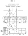
- FIG. 18 illustrates a method by superimposition, which is a first example of the related art.
- a head forms dots onto printing paper by ejecting droplets while moving in the arrow direction (the direction from left to right).
- the head forms dots a 1 and a 2 by ejecting droplets so that regions in which the dots a 1 and s 2 are formed can overlap with each other.
- the second movement indicated by the solid line in FIG.
- the head forms dots a 3 and a 4 by ejecting droplets so that the dots a 3 and a 4 can respectively overlap with the dots a 1 and a 2 formed in the first movement and so that the dots a 3 and a 4 , which are adjacent in the head moving direction, can overlap with each other.
- one pixel composed of the four dots a 1 , a 2 , a 3 , and a 4 is formed.
- This formation of one pixel from the four dots a 1 to a 4 can express five gradations, including the case of no dot. Also, by increasing the precision of the dot-formed positions in the first and second movements, a high quality image can be obtained.
- FIG. 19 illustrates a method by droplet amount, which is a second example of the related art.
- a head can switch the amount of droplets for ejection to three levels.
- the head forms a pixel by using any of a small dot b 1 , an intermediate dot b 2 , and a large dot b 3 . It is said that this method can increase printing speed.
- FIG. 20 illustrates a method by the number of dots, which is a third example of the related art.
- dots c 1 , c 2 , . . . whose diameters are smaller than a dot pitch are consecutively ejected.
- the next dot is formed so as to, at least, overlap with the first delivered dot.
- dots c 2 , c 3 , and c 4 are sequentially formed before the dot c 1 is absorbed by (infiltrates) the printing paper. This forms a larger dot c 5 (in this case, dot c 5 corresponds to one pixel).
- the dots a 1 to a 4 must be formed in one pixel formation region a plural number of times (four times in the first example).
- a photograph or the like which has many gradations requires a longer printing time, compared with the case of printing a document.
- some number of gradations can be obtained, there is a limitation in increasing the number of gradations.
- a time is required to fill the ink ejecting portions with ink for the ejected ink.
- a certain amount of time is needed until re-ejection of droplets.
- a certain amount of time is required from ejection of the droplet for forming the dot c 1 to ejection of the droplet for forming the dot c 2 .
- the movement speed of the head is very small when the head is moved so that, after the ink ejecting portions are filled with ink, in one pixel formation region, the dots c 2 , c 3 , and c 4 can be formed before the formed dot c 1 is absorbed by (infiltrates) the printing paper. Accordingly, this case is not practical.
- a method that forms one dot a 5 so that the dots a 1 to a 4 overlap with one another, and a method that forms one dot c 5 so that the dots c 1 to c 4 overlap with one another are characteristic in a serial method in which the head ejects ink droplets while moving back and forth in a line direction (the direction perpendicular to the traveling direction of the printing paper). Accordingly, in the case of a line head whose head portion cannot move in the line direction since nozzles are arranged in parallel in a width direction, a method such as the first example or the third example cannot substantially be employed. This is because, since the line head does not move in the line direction, the first and third examples cannot cope with a situation in which some nozzles have a defect such as no ejection of droplets.
- a liquid ejecting device having at least one head including a plurality of liquid ejecting portions each having a nozzle.
- the liquid ejecting device includes an ejection deflector for ejecting a droplet with deflection from the nozzle of each of the plurality of liquid ejecting portions in a plurality of directions, and an ejection controller for controlling ejection so that, by ejecting droplets in different directions from at least two different liquid ejecting portions in adjacent positions among the plurality of liquid ejecting portions while using the ejection deflector, the droplets are delivered in a single column to form a pixel column, or the droplets are delivered in a single pixel region to form a pixel.
- a pixel column or a pixel is formed.
- the droplets can be delivered in a single pixel region or a single pixel-region column.
- a pixel or a pixel column can be formed by using different liquid ejecting portions.
- a liquid ejecting device having at least one head including a plurality of liquid ejecting portions each having a nozzle.
- the liquid ejecting device includes an ejection deflector for ejecting a droplet with deflection from the nozzle of each of the plurality of liquid ejecting portions so that the droplets are delivered to positions to which droplets ejected from the nozzle of either adjacent liquid ejecting portion are delivered without being deflected, or the vicinity thereof, and an ejection controller in which, when a pixel column or a pixel is formed by delivering droplets so that at least two regions to which the droplets are delivered can overlap with each other, by using at least two different liquid ejecting portions in adjacent positions among the plurality of liquid ejecting portions and by using the ejection deflector to eject droplets with deflection from at least one of the two different liquid ejecting portions, the pixel column or the pixel can be formed.
- At least one droplet can be ejected without being deflected, and the droplets can be delivered so that the droplets are delivered to positions to which droplets ejected from the nozzle of another adjacent liquid ejecting portion are delivered without being deflected, or the vicinity thereof.
- the liquid ejecting portion N can eject and deliver the droplet to the position N without deflecting the droplet, and can eject and deliver the droplet to the position (N+1) by deflecting the droplet.
- the liquid ejecting portion (N+1) can eject and deliver the droplet to the position (N+1) without deflecting the droplet, and can eject and deliver the droplet to the position N by deflecting the droplet.
- ejection is controlled so that, by using at least two different liquid ejecting portions in adjacent positions and by deflecting droplets ejected from at least one of the liquid ejecting portions, the pixel column or the pixel is formed. For example, after a droplet is ejected and delivered from the liquid ejecting portion N to the position N without being deflected, a droplet is ejected and delivered from the liquid ejecting portion (N+1) to the position N, with it deflected.
- a pixel column or a pixel can be formed.
- a liquid ejecting method using at least one head including a plurality of liquid ejecting portions each having a nozzle is provided. Droplets are ejected from the nozzle of each of the plurality of liquid ejecting portions with deflection in a plurality of directions, and by ejecting droplets in different directions from at least two different liquid ejecting portions in adjacent positions among the plurality of liquid ejecting portions, the droplets are delivered in a single column to form a pixel column, or the droplets are delivered in a single pixel region to form a pixel.
- a liquid ejecting method using at least one head including a plurality of liquid ejecting portions each having a nozzle is provided. At least one droplet is ejected from the nozzle of each of the plurality of liquid ejecting portions with deflection so that the droplet is delivered to a position to which a droplet ejected from the nozzle of another adjacent liquid ejecting portion without being deflected is delivered, or the vicinity thereof, and when a pixel column is formed or when a pixel is formed by delivering droplets so that at least two regions in which the droplets are delivered can overlap with each other, by using at least two different liquid ejecting portions in adjacent positions among the plurality of liquid ejecting portions, and by deflecting droplets ejected from at least one of the two different liquid ejecting portions, the pixel column or the pixel is formed.
- FIG. 1 is an exploded perspective view showing a head of an inkjet printer to which a liquid ejecting device of the present invention is applied;
- FIG. 2 consists of a detailed plan view and side sectional view showing the arrangement of heating resistors
- FIG. 3 consists of graphs showing the relationship obtained in the case of each separate heating resistor 13 as in this embodiment between a difference in bubble producing time of ink and the ejection angle of ink droplets;
- FIG. 4 is a side sectional view showing the relationship between nozzles and printing paper
- FIG. 5 is a conceptual circuit diagram showing a circuit in which the difference in bubble producing time of bisected heating resistors can be set;
- FIG. 6 is a table illustrating two methods (Method 1 and Method 2) for an ejection controller in the present invention and the related method;
- FIG. 7 is an illustration of the number of times (the time required for dot formation in each pixel position) which is required to form dots in pixel positions;
- FIGS. 8A , 8 B, and 8 C are illustrations of a “preset format” for controlling the ejection selector and a “format conforming to the preset format for the ejection selector” for controlling the ejection determiner;
- FIG. 9 is an illustration of the formation based on the above format of dots on printing paper.
- FIG. 10 is an illustration consisting of plan views showing an example of a line head
- FIG. 11 is a circuit diagram showing an ejection controlling circuit including an ejection deflector in a second embodiment of the present invention.
- FIG. 12 is an illustration of an example in which ink droplets are delivered from ink ejecting portions adjacent to a pixel
- FIG. 13 is a front view showing directions in which ink droplets are delivered from adjacent heads in an alternate pattern arrangement
- FIG. 14 is an illustration of an example of setting an odd number of directions for ejection by using deflected ejection of ink droplets in right and left symmetric directions and directly-below ejection of ink droplets;
- FIG. 15 is an illustration of a process of forming pixels on printing paper by ink ejecting portions based on ejection-executing signals in the case of two-directional ejection (the number of directions for ejection is even);
- FIG. 16 is an illustration of a process of forming pixels on printing paper by ink ejecting portions based on ejection-executing signals in the case of three-directional ejection (the number of directions for ejection is odd);
- FIG. 17 is a circuit diagram showing an ejection-control circuit in a third embodiment of the present invention.
- FIG. 18 is an illustration of a method by superimposition, which is a first example of a related method
- FIG. 19 is an illustration of a method by droplet amount, which is a second example of the related method.
- FIG. 20 is an illustration of a method by the number of dots, which is a third example of the related method.
- an “ink droplet” is a minute quantity (e.g., several picoliters) of ink (liquid) ejected from a nozzle 18 (described later).
- a “dot” is a spot formed such that one ink droplet is delivered onto printing paper or the like.
- a “pixel” is the smallest unit of an image.
- a “pixel region” is a region in which a dot is formed.
- a pixel (with one gradation) having no dot, a pixel (with two gradations) composed of one dot, or a pixel (with three or more gradations) composed of plural dots is formed.
- one pixel region corresponds to one, or zero or plural dots.
- An image is formed by arranging, on a recording medium, a great number of pixels as described.
- Each dot corresponding to a pixel may protrude from the pixel region without completely falling in the pixel region.
- FIG. 1 is an exploded perspective view showing a head 11 of an inkjet printer (hereinafter referred to simply as a “printer”) to which a liquid ejecting device of the present invention is applied.
- a nozzle sheet 17 is bonded to a barrier layer 16 , and the nozzle sheet 17 is shown in an exploded form.
- a substrate member 14 includes a semiconductor substrate 15 composed of silicon or the like, and heating resistors 13 (corresponding to energy generating elements or heating elements in the present invention) formed on one surface of the semiconductor substrate 15 .
- the heating resistors 13 are electrically connected to an external circuit by a conductor portion (not shown) formed on the semiconductor substrate 15 .
- the barrier layer 16 is formed by, for example, an exposure-hardening dry film resist, and is formed by stacking the resist on the entirety of the surface of the semiconductor substrate 15 on which the heating resistors 13 are formed, and subsequently removing unnecessary portions in a photolithography process.
- the nozzle sheet 17 has a plurality of nozzles 18 therein, and is formed by, for example, electroforming technology using nickel.
- the nozzle sheet 17 is bonded onto the barrier layer 16 so that the positions of the nozzles 18 can correspond to the positions of the heating resistors 13 , that is, the nozzles 18 can oppose the heating resistors 13 .
- Ink cells 12 are constituted so as to surround the heating resistors 13 by the substrate member 14 , the barrier layer 16 , and the nozzle sheet 17 .
- the substrate member 14 forms the bottom walls of the ink cells 12
- the barrier layer 16 forms the side walls of the ink cells 12
- the nozzle sheet 17 forms the top walls of the ink cells 12 .
- the ink cells 12 have aperture regions in the front right of FIG. 1 . The aperture regions are connected to ink-flow paths (not shown).
- the above head 11 normally includes the ink cells 12 in units of hundreds, and the heating resistors 13 , which are disposed in the ink cells 12 .
- each heating resistor 13 is uniquely selected, and the ink of the ink cell 12 corresponding to the heating resistor 13 can be ejected from the nozzle 18 opposing the ink cell 12 .
- the ink cell 12 is filled with ink supplied from an ink container (not shown) joined to the head 11 .
- the heating resistor 13 is rapidly heated.
- a gas-phase ink bubble is produced in a portion in contact with the heating resistor 13 , and the expansion of the ink bubble dislodges ink of some volume (the ink boils).
- ink of a volume equal to that of the dislodged ink in the portion touching the nozzle 18 is ejected as an ink droplet from the nozzle 18 , and is delivered onto the printing paper, thus forming a dot.
- a portion constituted by one ink cell 12 , the heating resistor 13 disposed in the ink cell 12 , and the nozzle 18 disposed thereon is referred to also as an “ink ejecting portion (liquid ejecting portion)”.
- the head 11 has a plurality of ink ejecting portions arranged in parallel.
- the head 11 includes an ejection deflector.
- the ejection deflector deflects an ink droplet ejected from one nozzle 18 so that the ink droplet can be delivered to a position to which an ink droplet from another adjacent nozzle 18 can be delivered without being deflected, or the vicinity thereof.
- the head 11 has the following structure.
- FIG. 2 consists of a detailed plan view and side sectional view showing the arrangement of the heating resistors 13 in the head 11 .
- the position of the nozzle 18 is indicated by the chain lines.
- one ink cell 12 includes bisected heating resistors 13 arranged in parallel.
- the direction in which the heating resistors 13 are arranged is a direction (the horizontal direction in FIG. 2 ) in which the nozzles 18 are arranged.
- each separated heating resistor 13 has the same length and a half width.
- the resistance of the bisected heating resistors 13 is double that of the original heating resistor 13 .
- the heating resistor 13 in order that the ink in the ink cell 12 may boil, the heating resistor 13 must be heated by supplying a certain amount of power to it. This is because energy generated at the boil is used to eject the ink. When the resistance is small, a current to flow must be increased. However, by increasing the resistance of the heating resistor 13 , the ink can be brought to a boil with a small current.
- the resistance can be increased.
- material selected for the heating resistor 13 and its strength (durability) there is a limitation in reducing the thickness of the heating resistor 13 . Accordingly, by separating the heating resistor 13 without reducing its thickness, its resistance is increased.
- one ink cell 12 includes the bisected heating resistors 13 , if the time (bubble producing time) required for each heating resistor 13 to reach a temperature for boiling the ink is set to be equal, the inks boil on two heating resistors 13 and an ink droplet is ejected in the central axis direction of the nozzle 18 .
- FIGS. 3A and 3B are graphs showing the relationship obtained in the case of each separate heating resistor 13 in this embodiment between a difference in bubble producing time of ink and the ejection angle of ink droplet.
- the values shown in the graphs are computer-simulated results.
- the X-direction (the direction indicated by vertical axis ⁇ x of the graph) (note that the X-direction does not mean the horizontal axis of the graph) indicates a direction (the direction of the heating resistors 13 arranged in parallel) in which the nozzles 18 are arranged.
- the Y-direction (the direction indicated by vertical axis ⁇ y of FIG.
- FIG. 3C is a graph showing actually measured data.
- a deflection current (We use a half of a difference current between the bisected heating resistors 13 in FIG. 3C ) is indicated as difference in bubble producing time between the bisected heating resistors 13 by the horizontal axis, and an amount of deflection (actually measured when the distance between the nozzle and a position to which ink is delivered was set at approximately 2 mm) in the position to which ink is delivered is indicated as the angle (X-direction) of ejection of ink by the vertical axis.
- FIG. 3C also shows a case in which, with the main current of the heating resistors 13 set to 80 mA, the deflection current was superimposed on one of the heating resistors 13 and the ink was ejected and deflected.
- the heating resistors 13 When the resistances of the bisected heating resistors 13 are not equal to each other due to, for example, a production error or the like, the heating resistors 13 have a difference in bubble producing time. Thus, the angle of ejection of ink is not perpendicular, so that the position to which the ink is delivered is off from the correct position. However, by supplying different currents to the heating resistors 13 for controlling the bubble producing time of each heating resistor 13 to be equal, the angle of ejection of ink can be set at perpendicularity.
- an angle at which an ink droplet is ejected can be changed by setting the bisected heating resistors 13 to have a difference in bubble producing time.
- FIG. 4 is a side sectional view showing the relationship between the nozzles 18 and printing paper P.
- the distance H must be maintained to be almost constant is because a change in the distance H causes a change in the position to which each ink droplet is delivered.
- the position to which the ink droplet is delivered does not change, even if the distance H is slightly changed.
- the position to which the ink droplet is delivered differs in accordance with a change in the distance H.
- the interval between adjacent nozzles 18 is 25.40 ⁇ 1000/600 ⁇ 42.3 ( ⁇ m)
- the direction in which ink droplets are ejected from the nozzles 18 is changed to 2 J different directions by using a control signal represented by J bits (where J represents a positive integer), and the distance between farthest positions of two delivered ink droplets among the 2 J directions is set so as to be (2 J ⁇ 1) times the interval between two adjacent nozzles 18 .
- J represents a positive integer
- the number of types of the control signal is four, that is, (0, 0) , (0, 1) , (1, 0), and (1, 1).
- the position of a delivered ink droplet can be moved by the interval between adjacent nozzles 18 .
- FIG. 5 is a schematic circuit diagram showing a circuit in which the difference in bubble producing time of the bisected heating resistors 13 can be set.
- the ejected ink droplet can be set to have four directions for ejection.
- the resistors Rh-A and Rh-B correspond to the resistances of the bisected heating resistors 13 , respectively.
- the resistance of the resistor Rh-A is set to be less than that of the resistor Rh-B.
- the resistors Rh-A and Rh-B have a junction (intermediate point) therebetween from which a deflection current can flow.
- Three resistors Rd are used to deflect an ejected ink droplet.
- transistors Q 1 , Q 2 , and Q 3 function as switches for the resistors Rh-A, Rh-B, and Rds.
- the circuit in FIG. 5 includes an input portion C for a binary control input signal (whose state is “1” only when a current flows). It includes binary-input AND gates L 1 and L 2 , and input portions B 1 and B 2 for binary signals (“0” or “1”) for the AND gates L 1 and L 2 .
- the position to which the ejected ink droplet is delivered is set to be a position (including its vicinity) to which an ink droplet ejected from a nozzle 18 (ink ejecting portion) left from a reference position with one nozzle 18 therebetween is delivered without being deflected ( FIG. 8B ).
- the position to which ejected ink droplets are delivered is set to be a position to which ink droplets ejected from the adjacent left nozzle 18 are delivered without being deflected.
- the position to which ejected ink droplets are delivered is set to be a position to which ink droplets ejected from the adjacent right nozzle 18 as an ink ejecting portion are delivered without being deflected.
- Rd may be set so that, whenever the inputs to the input portions B 1 and B 2 change to (0, 0), (1,0), (0, 1), and (1, 1), the position to which the ejected ink droplets are delivered can move at each interval between the nozzles 18 .
- the ink droplet can be delivered to an arbitrary position among the above four positions ( FIG. 8
- the embodiment described thus far also includes an ejection controller.
- the ejection controller controls the formation of ink droplets (dots) in such a manner that, by using the ejection deflector, when ink droplets are delivered in line (almost in the same row) to form a dot column, or ink droplets are delivered to form one dot in a form in which at least some regions of delivered droplets overlap with each other, at least two different ink ejecting portions adjacently positioned are used and ink droplets ejected from at least one of the ink ejecting portions are deflected by the ejection deflector to form a pixel column or pixel.
- FIG. 6 is a table illustrating two methods (Method 1 and Method 2) for the ejection controller in the present invention and a method of the related method.
- FIG. 6 also shows the case of forming one pixel by arranging ink droplets in column so that at least some regions of delivered droplets overlap with each other.
- Method 2 is an example in which the position to which ink droplets ejected from each ink ejecting portion are delivered can be selected from among four positions, as described above.
- the arrangements of dots are not shown straight. This shows that the dots are ejected from a plurality of ink ejecting portions.
- pixel numbers in the direction of ink ejecting portions are indicated by N, (N+1) (N+2), and (N+3).
- ink ejecting portions from which ejected ink droplets are delivered to pixel numbers N, (N+1), (N+2), and (N+3) without being deflected are referred to as N, (N+1), (N+2), and (N+3), respectively (Ejecting portions are not indicated in FIG. 6 ).
- ink droplets are ejected from the ink ejecting portions N, (N+1), (N+2), and (N+3) without being deflected, and are delivered to pixel numbers N, (N+1), (N+2) , and (N+3) to form dots corresponding to pixels.
- a case in which no ink droplets are ejected corresponds to a case in which the number of gradations is 1.
- an ink droplet is ejected and delivered from the ink ejecting portion (N ⁇ 1) which is positioned at left of N in FIG. 6 ((N ⁇ 1) is not indicated in FIG. 6 , Ejecting portion which is positioned at left of (N ⁇ 1) is (N ⁇ 2), . . . , and so on), with it deflected.
- N+1 an ink droplet is ejected and delivered from the ink ejecting portion N, with it deflected.
- an ink droplet is ejected and delivered from the ink ejecting portion (N+1), with it deflected.
- an ink droplet is ejected and delivered from the ink ejecting portion (N+2), with it deflected.
- an ink droplet is ejected from the ink ejecting portion (N ⁇ 2), with it deflected, and is delivered.
- N+1 an ink droplet is ejected from the ink ejecting portion (N ⁇ 1), with it deflected, and is delivered.
- N+2 an ink droplet is ejected from the ink ejecting portion N, with it deflected, and is delivered.
- To pixel number (N+3) an ink droplet is ejected from the ink ejecting portion (N+1), with it deflected, and is delivered.
- ink droplets ejected from the ink ejecting portion (N ⁇ 3) are deflected and delivered to pixel number N.
- Method 1 shows a 1-bit example.
- each ink ejecting portion can eject ink droplets without deflection, and can deliver the ink droplets to a position to which an ejected ink droplet can be delivered from an adjacent ink ejecting portion.
- an ink droplet is ejected from the ink ejecting portion N without being deflected, and can be delivered to a position to which an ink droplet is ejected and delivered from the ink ejecting portion (N+1) without being deflected.
- N and N+1 pixel numbers in a direction in which the ink ejecting portions (the nozzles 18 , Ejecting portions are not indicated in FIG. 6 ) are arranged are indicated by N and N+1. Also, ink ejecting portions that deliver ink droplets to pixel numbers N and (N+1) when ejecting the ink droplets without deflection are referred to as N and (N+1), respectively.
- ink droplets are ejected from the ink ejecting portions N and (N+1) without being deflected, and are delivered to pixel numbers N and N+1 to form a pixel (dot) corresponding to the gradation number 2.
- ink droplets ejected from the ink ejecting portion (N ⁇ 1) are deflected and is delivered. Also, to the pixel number (N+1), ink droplets are ejected from the ink ejecting portion N and are delivered.
- ink droplets ejected from the ink ejecting portion (N ⁇ 1) are deflected and delivered.
- N+1 ink droplets ejected from the ink ejecting portion N is deflected and is delivered.
- a dot can be formed such that the same ink ejecting portion does not deliver ink droplets consecutively (sequentially two times).
- a change in the dot for each ink ejecting portion can be reduced.
- a variation in the areas occupied by dots of pixels can be reduced.
- the vertical direction represents an arbitrary time domain
- the horizontal direction represents an arbitrary distance
- the arbitrary time domain corresponds to timing with which the ejection of ink droplets in accordance with the number of gradations is executed
- the arbitrary distance corresponds to a pixel position corresponding to the direction of arranged nozzles 18 .
- FIG. 7 shows the number of times (i.e., the time required for dot formation in each pixel) an ink droplet is ejected which is required for forming a dot in each pixel position.
- lines (which are formed during a first (the same) scanning term) in the direction of arranged nozzles 18 for the pixels are defined as pixel lines.
- each pixel has ink-droplet-ejection timing 1 to ink-droplet-ejection timing P, and these are indicated by time slots.
- a dot is formed by a maximum of P ink droplets (i.e., the maximum number of gradations is P+1 including no droplet).
- the first to N-th pixel positions are horizontally indicated in FIG. 7 . Accordingly, the number of the nozzles 18 in the arrangement direction is also N.
- an ink droplet is ejected four times and the four ink droplets form a dot for the pixel number 1 .
- an ink droplet is ejected three times, whereby three regions occupied by the dots are formed in the pixel region corresponding to the pixel number 1 in the (M+1) line.
- the pixel number 1 in the M-th line and the pixel number 1 in the (M+1)-th line are delivered almost in the same (pixel) column. Pixels in other pixel numbers are also in a similar situation.
- a pixel formed at pixel (column) number 1 , and the M-th pixel line by one or more ink droplets, and a pixel formed at the pixel column number 1 and the (M+1)-line by one or more ink droplets are delivered almost in the same column, in this embodiment.
- one of ink ejecting portions for ejecting the first ink droplet to form the pixel in the M-th line, and one of the ink ejecting portions for ejecting the first ink droplet to form the pixel in the (M+1)-th line can be controlled to differ from each other.
- dots formed by the same ink ejecting portion are not delivered in consecutive positions in the same column.
- the same ink ejecting portion which is first used to form the dots should be used alternately with others which can deliver dots to the same pixel column.
- ink ejecting portions may randomly be selected other than the above technique.
- One of an ink ejecting portion for forming the dot in the M-th line and an ink ejecting portion for ejecting the first ink droplet for forming the dot in the M-th line, and one of an ink ejecting portion for forming the dot in the (M+1)-line and an ink ejecting portion for ejecting the first ink droplet for forming the dot in the (M+1)-th line may be controlled so as not to be always the same.
- the ejection controller includes an ink-ejecting-portion selector and an ejection-direction controller.
- the ink-ejecting-portion selector selects one or more ink ejecting portions for ejecting ink droplets from among a plurality of ink ejecting portions.
- the ejection-direction controller determines an ink-droplet ejecting direction based on a format conforming to the above format set for ink-ejecting-portion selection by the ink-ejecting-portion selector.
- FIG. 8A illustrates how an image signal as an ejection executing signal is sent to ink ejecting portions. For example, as shown in FIG.
- an ejection executing signal for forming a dot for pixel N is supplied to ink ejecting portion N (an ink ejecting portion that ejects an ink droplet to pixel N when the ejection is not deflected) and ink ejecting portions (N ⁇ 1), (N+1), and (N+2) which are adjacent to ink ejecting portion N in the cycle of a, b, c, and d.
- the ejection executing signal corresponds to an image signal in which the maximum number of gradations is 5.
- this invention can form a different maximum number of gradations.
- 2 cycles of a, b, c, d can form a maximum number of gradations 9.
- 1.5 cycles can form a maximum number of gradations 7.
- 0.5 cycles can form a maximum number of gradations 3, etc.
- the ejection-direction controller deflects the ejection in the cycle of a, b, c, and d.
- an ejection executing signal inputted with timing “a” in the cycle of a, b, c, and d is sent to the ink ejecting portion (N ⁇ 1) in FIG. 8A , and from the ink ejecting portion (N ⁇ 1), an ink droplet is ejected and deflected to the direction a targeted to the pixel position N in FIG. 8B .
- an ink droplet is ejected and deflected to the region of pixel N.
- Control of the ink ejection is performed based on the signals B 1 and B 2 .
- Correspondences between signals B 1 and B 2 as 2-bit signals, and the cycle of a, b, c, and d are shown in FIG. 8C .
- FIG. 9 is used to describe the formation based on the above format of dots on printing paper.
- FIG. 9 shows the process of the formation, based on ejection executing signals sent in parallel to the head 11 , of dots for pixels on printing paper by ink ejecting portions.
- the ejection executing signals correspond to the image signals.
- the number of gradations of the ejection executing signal for the pixel N is set to 5
- the number of gradations of the ejection executing signal for the pixel (N+1) is set to 2
- the number of gradations of the ejection executing signal for the pixel (N+2) is set to 4
- the number of gradations of the ejection executing signal for the pixel (N+3) is set to 3.
- the ejection signal for each pixel is sent to each predetermined ink ejecting portion in the cycle of a, b, c, and d, and in the same cycle, each ink ejecting portion ejects deflected ink droplets having the cycle of a, b, c, and d.
- the periods a, b, c, and d correspond to time slots a, b, c, and d, respectively, and one cycle of a, b, c, and d forms one dot for one pixel.
- an ejection executing signal for the pixel N is sent to the ink ejecting portion (N ⁇ 1)
- an ejection executing signal for the pixel (N+1) is sent to the ink ejecting portion N
- an ejection executing signal for the pixel (N+2) is sent to the ink ejecting portion (N+1)
- an ejection executing signal for the pixel (N+3) is sent to the ink ejecting portion (N+2).
- the ink droplet is ejected in the a-direction with deflection, and is delivered to the position of the pixel N on the printing paper. Also, from the ink ejecting portion N, the ink droplet is ejected in the a-direction with deflection, and is delivered to the position of the pixel (N+1) on the printing paper. Also, from the ink ejecting portion (N+1), the ink droplet is ejected in the a-direction with deflection, and is delivered to the position of the pixel (N+2) on the printing paper. Also, from the ink ejecting portion (N+2), the ink droplet is ejected in the a-direction with deflection, and is delivered to the position of the pixel (N+3) on the printing paper.
- a dot corresponding to the number of gradations being 5 is formed in the pixel N.
- a dot corresponding to the number of gradations being 2 is formed in the pixel (N+1).
- a dot corresponding to the number of gradations being 4 is formed in the pixel (N+2).
- a dot corresponding to the number of gradations being 3 is formed in the pixel (N+3).
- the ejection controller includes a deflection controller that determines whether the ejection deflector deflects the ink droplets ejected from the nozzles 18 .
- the ink ejecting portions instead of controlling the ink ejecting portions to always eject ink droplets with deflection, based on printing conditions such as an object to be printed and printing speed, it can be determined whether the ejected ink droplets are deflected. For example, by providing a printer operation unit or the like with a deflection controller, a printer user can switch between operation modes depending on a purpose of use.
- the normal mode is set as the operation mode, and ink droplets are ejected as usual so that positions to which the ink droplets are delivered respectively correspond to ink ejecting portions (i.e., the ink droplets are ejected without being deflected).
- a plurality of different ink ejecting portions are used to form one pixel, and at least one ink ejecting portion is controlled to eject and deflect an ink droplet to form a pixel.
- the above printing control enables efficient printing.
- the present invention can be applied to a serial head which includes a single head 11 and in which the head 11 performs printing while moving in the line direction, and also to a line head in which heads 11 are arranged in parallel in the direction of the ink ejecting portions.
- FIG. 10 consists of plan views showing an example of a line head 10 .
- FIG. 10 shows four heads 11 (N ⁇ 1, N, N+1, and N+2).
- heads 11 N ⁇ 1, N, N+1, and N+2.
- a plurality of heads 11 are arranged each of which is formed by the portion (chip) of the head 11 in FIG. 1 excluding the nozzle sheet 17 .
- the line head 11 By bonding, onto the top of the heads 11 , a nozzle sheet 17 in which nozzles 18 are formed in positions corresponding to the ink ejecting portions of the heads 11 , the line head 11 is formed.
- each head 11 cannot move in the line direction.
- the related art only forms a dot by ejecting ink from a single ink ejecting portion.
- a plurality of adjacent different ink ejecting portions are used to form a dot composed of plural gradations.
- the line head 10 when ink droplets cannot be ejected or there is an ink ejecting portion that ejects insufficient ink, in a pixel column corresponding to the ink ejecting portion, ink droplets are not ejected at all, or the ink droplets are hardly ejected. Thus, no dot is formed to appear as a vertical white stripe, thus deteriorating printed image quality.
- the present invention instead of the ink ejecting portion that cannot eject sufficient ink, other adjacent ink ejecting portions can eject ink droplets. Accordingly, an advantage obtained by applying the present invention to the line head 10 is larger than that of the serial head.
- the ejection deflector in the first embodiment is disclosed as a more specific example, the direction of an ink droplet ejected from the nozzle 18 can be more variously set compared with the first embodiment.
- the first embodiment has four directions in which an ink droplet is ejected from the nozzle 18 , as shown in FIG. 8 .
- the present invention is not limited to the directions of ejection shown in the first embodiment.
- the second embodiment describes an example in which an ink droplet can be ejected in eight directions (composed of equal numbers of right and left directions) in the direction of the arranged nozzles 18 with respect to the central axes of the nozzles 18 (ink ejecting portions), as described later.
- FIG. 11 shows an ejection-control circuit 50 including an ejection deflector in the second embodiment.
- bisected resistors 13 (resistors Rh-A and Rh-B in FIG. 11 ) in the ink cell 12 are connected in series.
- the resistances of the resistors 13 are set to be almost equal to each other.
- a current-mirror circuit (hereinafter referred to as a “CM circuit”) is connected to (the midpoint of the) two heating resistors 13 connected to each other in series.
- CM circuit By using the CM circuit to allow a current to flow into or to flow out from a junction of the heating resistors 13 , a difference is set in the amounts of currents flowing in the heating resistors 13 . Based on the difference, ejection is controlled so that an ink droplet ejected from the nozzle 18 can be deflected in the direction of the arranged nozzles 18 (ink ejecting portions).
- the use of the above structure in the second embodiment can more flexibly set a direction in which an ink droplet is ejected, compared with the first embodiment.
- a power supply Vh is used to apply a voltage to the resistors Rh-A and Rh-B.
- the ejection-control circuit 50 in FIG. 11 includes transistors M 1 through to M 21 .
- the transistors M 4 , M 6 , M 9 , M 11 , M 14 , M 16 , M 19 , and M 21 are PMOS transistors, and the other transistors are NMOS transistors. Pairs of the transistors M 4 and M 6 , M 9 and M 11 , M 14 and M 16 , and M 19 and M 21 constitute CM circuits, respectively.
- the ejection-control circuit 50 includes four CM circuits.
- the gate and drain of the transistor M 6 are connected to the gate of the transistor M 4 .
- equal voltages are constantly applied to the transistors M 4 and M 6 , and almost equal currents can flow in them. This similarly applies to the other CM circuits.
- the transistors M 3 and MS function as a current switch circuit by which a current (generated by M 2 ) is controlled either to flow into the resistors Rh-A and Rh-B through the CM circuit composed of the transistors M 4 and M 6 , or to flow out from the junction of the resistors Rh-A and Rh-B via transistor M 3 .
- pairs of the transistors M 8 and M 10 , M 13 and M 15 , and M 18 and M 20 are respectively second switching elements for the CM circuits formed by the pairs of the transistors M 9 and M 11 , M 14 and M 16 , and M 19 and M 21 .
- the drains of the transistors M 4 and M 3 are connected to each other, and the drains of the transistors M 6 and M 5 are connected to each other. This shape also applies to all other switching elements (in this embodiment).
- the drains of the transistors M 4 , M 9 , M 14 , and M 19 which are parts of the current-mirror circuits, and the drains of the transistors M 3 , M 8 , M 13 , and M 18 are connected to the midpoint of the resistors Rh-A and Rh-B.
- the drain currents of the transistors M 2 , M 7 , M 12 , and M 17 are used as constant current sources for the CM circuits, and their drains are respectively connected to the sources and backgates of the transistors M 3 , M 8 , M 13 , and M 18 .
- the drain of the transistor M 1 is connected in series with the resistor Rh-B. It is turned on when an ejection-executing input switch A is in the state “1” (ON), and allows a current to flow in the resistors Rh-A and Rh-B (simultaneously). In other words, the transistor M 1 serves as a switch to supply current to the resistors Rh-A and Rh-B.
- the output terminals of AND gates X 1 through to X 9 are connected to the gates of the transistors M 1 , M 3 , M 5 , etc.
- the AND gates X 1 through to X 7 are of a two-input type, and the AND gates X 8 and X 9 are of a three-input type. At least one of the input terminals of the AND gates X 1 through to X 9 is connected to the ejection-executing input switch A.
- XNOR gates X 10 , X 12 , X 14 , and X 16 each have an input terminal connected to a deflection-direction switch C, and the other input terminals of the XNOR gates X 10 , X 12 , X 14 , and X 16 are connected to deflection-control switches J 1 through to J 3 and a deflection-angle correcting switch S, respectively.
- the deflection-direction switch C is used to switch the direction of ink-droplet ejection in either direction (for the same control signal) in which the nozzles 18 are arranged.
- the deflection-direction switch C changes its state (“0” to “1” or “1” to “0”), input logic (provided with nodes J 1 through to J 3 and S) of the other inputs of the XNOR gate X 10 , X 12 , X 14 , and X 16 are inverted.
- the deflection-control switches J 1 through to J 3 are used to determine an amount of deflection for changing the direction of ink-droplet ejection. For example, when the input terminal J 3 is in the state “1” (ON), while another input of the same gate connected to the switch C is “1”, the output of the XNOR gate X 10 is “1”.
- each of the XNOR gates X 10 , . . . , X 16 is connected to one input terminal of each of the AND gates X 2 , . . . , X 8 and is connected by way of each of NOT gates X 11 , . . . , X 17 to one input terminal of each of the AND gates X 3 , . . . , X 9 .
- One input terminal of each of the AND gates X 8 and X 9 is connected to an ejection-angle correcting switch K.
- a deflection-amplitude control terminal B is used to determine a current for the transistors M 2 , . . . , M 17 used as the constant current supplies for the CM circuits, and is connected to the gate of each of the transistors M 2 , . . . , M 17 . Since the application of an appropriate voltage (Vx) to the deflection-amplitude control terminal B supplies a gate-source voltage (Vgs) to all the gates of the transistors M 2 , . . . , M 17 , currents flow in each drain of the transistors M 2 , . . . , M 17 .
- the representation “X 1 ” (M 12 , . . . , M 21 ) represents a standard element.
- the representation “X 2 ” (M 7 , . . . , M 11 ) represents an element equivalent to one in which two standard elements are connected in parallel.
- the representation “XN” represents an element equivalent to one in which N elements are connected in parallel.
- the transistors M 2 , M 7 , M 12 , and M 17 have the representations “X 4 ”, “X 2 ”, “X 1 ”, and “X 1 ”, respectively. Thus, by applying an appropriate voltage across the gate and ground of each transistor, their drain currents are in the ratio of 4:2:1:1.
- the drain current of each transistor M 2 , . . . , M 17 is proportional to those numbers in the parentheses.
- the current-mirror circuit composed of the transistors M 4 and M 6 , and the transistors M 3 and M 5 used as a switching element therefor are described below.
- the ejection-executing input switch A Only when the ejection-executing input switch A has the state “1” (ON), an ink droplet is ejected.
- the ejection-executing input switch A when an ink droplet is ejected from one nozzle 18 , the ejection-executing input switch A is set to be in the state “1” (ON) during a period of 1.5 microseconds (1/64), and the power supply Vh (approximately 9 V) supplies power to the resistors Rh-A and Rh-B. 94.5 microseconds (63/64) are assigned to a period in which an ink cell 12 having ejected an ink droplet is refilled with ink, with the ejection-executing input switch A set to be in the state “0” (OFF).
- the deflection-amplitude control terminal B has the voltage Vx (analog voltage)
- the deflection-direction switch C is in the state “1”
- the deflection-control switch J 3 is in the state “1”
- the output of the output of the XNOR gate is “1”.
- this output “1” and the state “1” of the ejection-executing input switch A are input to the AND gate X 2 , and the output of the AND gate X 2 is 1.
- the transistor M 3 is turned on.
- the drains of the transistors M 4 and M 3 are connected to each other and the drains of the transistors M 6 and M 5 are connected to each other, when the transistor M 3 is in ON state and the transistor M 5 is in OFF state, a current flows from the resistor Rh-A to the transistor M 3 , but no current flows to the transistor M 6 due to the OFF state of the transistor M 5 . Also, when no current flows to the transistor M 6 , no current also flows to the transistor M 4 due to the characteristics of the current-mirror circuit. Since the transistor M 2 is in ON state, in the above case, among the transistors M 3 , M 4 , M 5 , and M 6 , a current only flows from the transistor M 3 to M 2 .
- a current is supplied and flows in the resistor Rh-A, the transistors M 4 and M 6 from the power supply Vh. All the current passing through the resistor Rh-A flows in the resistor Rh-B (the current passing through the resistor Rh-A does not branch off to the transistor M 3 since it is in OFF state). All the current passing through the transistor M 4 flows into the resistor Rh-B since the transistor M 3 is in OFF state. The current passing through the transistor M 6 flows into the transistor M 5 .
- the ratio is symmetrical in both cases (the deflection-control switch J 3 is in states “1” and “0”)
- the deflection-control switch J 3 is in states “1” and “0”
- a difference is generated in bubble producing time between the bisected heating resistors 13 . This can change a direction in which an ink droplet is ejected.
- a direction in which an ink droplet is deflected can be symmetrically switched in position to the direction in which the nozzles 18 are arranged.
- the interval between two positions to which an ink droplet is delivered, when the deflection-control switch J 3 is in the state “1” and that of the deflection-control switch J 3 is in the state “0”, can be equal to the distance between two adjacent ink ejecting portions (the nozzles 18 ), and ink droplets can be delivered in a pixel region from the nozzles 18 of adjacent ink ejecting portions, as FIG. 12 shows.
- This case differs from that of the first embodiment in that the positions to which the ink droplets are delivered (position of pixel columns) are become the midpoint of the nozzles 18 .
- the deflection-control switch J 3 the current flowing in the transistors M 4 and M 6 can be controlled.
- the deflection-control switch J 2 the current flowing in the transistors M 9 and M 11 can also be controlled.
- the deflection-control switch J 1 currents flowing in the transistors M 14 and M 16 can be controlled.
- the amounts of the currents can be changed.
- an amount of deflection in one step can be changed by changing the drain currents in those transistors while maintaining their ratio as 4:2:1.
- the deflection-angle correcting switches S and K are similar to the deflection-control switches J 1 to J 3 in switch for changing the direction of ink-droplet ejection, but differ in the purpose of use in correcting the angle of ejection of ink droplet. Switches S and K can be controlled independently from Switches J. In this embodiment, two bits which form the deflection-angle correcting switches S and K are used for correction.
- the ejection-angle correcting switch K is used to determine whether or not correction is performed.
- the ejection-angle correcting switch K is set so that correction is performed when its state is “1” and-no correction is performed when its state is “0”.
- the deflection-angle correcting switch S is used to determine in which the correction of the direction on the arranged nozzles 18 is performed.
- both the outputs of the AND gates X 8 and X 9 are “0s” since at least one input of each of the AND gates X 8 and X 9 is “0”.
- the transistors M 18 and M 20 are turned off, which turns off the transistors M 19 and M 21 . This causes no change in the currents flowing in the resistors Rh-A and Rh-B.
- the characteristics of the current-mirror circuit cause no current to flow also in the transistor M 19 .
- the ON state of the transistor M 18 causes a current to flow from the midpoint of the resistors Rh-A and Rh-B into the transistor M 18 .
- the current in the resistor Rh-B can be reduced than that in the resistor Rh-A. Accordingly, the angle of ejection of ink droplet is corrected and the position to which the ink droplet is delivered can be corrected by a predetermined amount in the direction in which the nozzles 18 are arranged.
- the above correction is performed in units of ink ejecting portions or in units of heads 11 . It is common that directions in which ink droplets are ejected from the ink ejecting portions of one head 11 are not always constant but fluctuating. Normally, the range of the error (fluctuation) is defined, and when each direction (position to which an ink droplet is delivered) of ejection of ink droplet is within a predetermined range, the direction is treated as normal.
- the deflection-angle correcting switches S and K may be turned on or off.
- the deflection direction can be symmetrically changed in position in the direction in which the nozzles 18 are arranged.
- the heads 11 (having identical specifications or structures) are arranged in the width direction of printing paper and are arranged in a repeated pattern so that two adjacent heads 11 can oppose each other (every other head 11 is disposed with it rotated 180 degrees with respect to the adjacent head 11 ).
- the deflection directions in either head are opposing to those of the other head.
- the deflection-direction switch C of every other head chip by providing the same status (“1” or “0”) to the deflection-direction switch C of every other head chip, the direction of deflection in the entire head 11 can be made virtually identical to the common signal given at J 1 through to J 3 .
- the deflection-direction switch C is set to be in the state “0” for heads N, N+2, N+4, etc., for example, in the even-numbered positions among the heads 11 , and the deflection-direction switch C is set to be in the state “1” for the odd-numbered heads N+1, N+3, N+5, etc., whereby the direction of deflection in each head in the line head 20 can be set to be virtually constant.
- FIG. 13 is a front view showing directions in which ink droplets are ejected from adjacent heads 11 arranged in the repeated pattern.
- the adjacent heads 11 are referred to as heads N and N+1, respectively. If the deflection-direction switch C is not provided in this case, by setting each of the heads N and N+1 to deflect the direction of ink-droplet ejection by ⁇ from perpendicularity, as FIG. 13 shows, both heads have such symmetrical directions of ejection that the direction of ejection from the head N is changed to direction Z 1 and the direction of ejected from the head N+1 is changed to direction Z 2 because the heads N and N+1 are positioned so that every other head is disposed which it rotated 180 degrees with reference to the other.
- the direction of ejection from the head N can be changed to direction Z 1 and the direction of ejection from the head N+1 can be changed to direction Z 2 ′, so that the direction of ejection can be set to be constant in the direction in which the nozzles 18 are arranged.
- the directions of ejection from the heads 11 arranged in the repeated pattern can be identically set.
- a control signal is represented by (J (2 J )+1) bits, and the number of directions for ejection is an odd number of (2 J +1) different directions.
- each position to which an ink droplet is delivered corresponds in position to each nozzle 18 .
- FIGS. 15 and 16 respectively show processes in which, in the two-directional ejection case (the number of directions for ejection is even) and in the three-directional ejection case (the number of directions for ejection is odd) where pixels are formed on printing paper based on an ejection-executing signal sent to the head 11 by ink ejecting portions, which correspond to FIG. 9 of the first embodiment. Since the pixel forming processes in FIGS. 15 and 16 are similar to that described using FIG. 9 , descriptions thereof are omitted.
- FIGS. 15 and 16 show, various forms of ejection-executing signals sent to the head 11 can be set in the process by the ink ejecting portions of forming each pixel on the printing paper.
- the ejection-control circuit 50 in FIG. 11 includes four CM circuits
- the ejection-control circuit 50 A in FIG. 17 includes only a single CM circuit (composed of transistors M 31 and M 32 ), whereby simplification of the entire circuit structure is achieved.
- the transistors M 4 and M 6 are represented by “X 4 ” (number of transistors in parallel)
- the transistors M 9 and M 11 are represented by “X 2 ”
- the transistors M 14 and M 16 and the transistors M 19 and M 21 are represented by “X 1 ”
- devices represented by “X 8 ” are used for the transistors M 31 and M 32 so as to drain current capacities of those transistors equal to the sum of the drain current capacity of all the above transistors in the ejection-control circuit 50 .
- the entire circuit structure can be simplified, performing similar functions to those in the ejection-control circuit 50 in FIG. 11 .
- the switching element (second switching element compared with first switching by transistor M 1 ) of this current-mirror circuit only consists of transistors M 33 and M 34 .
- the transistors M 3 and M 5 are represented by “X 4 ”
- the transistors M 8 and M 10 are represented by “X 2 ”
- the transistors M 13 , M 15 , M 18 and M 20 are represented by “X 1 ”.
- devices represented by “X 8 ” are used for the transistors M 33 and M 34 so as to provide with enough drain current capacity equal to the sum of those of all the above transistors in FIG. 11 .
- the source and backgate of the transistor M 1 are connected to the ground.
- the sources of the transistors M 33 and M 34 are connected to the common circuit (current source) to be described later, and their backgates are connected to the ground.
- Each output of the NOR gates X 21 , X 22 , and X 23 are connected to the gates of the transistors M 1 , M 33 , and M 34 , respectively.
- the ejection-control circuit 50 A includes a circuit including current-source unit for supplying currents to the transistors M 33 and M 34 .
- the circuit includes a first control terminal Z, second control terminals D 1 , D 2 , and D 3 , and transistors M 61 through to M 66 .
- the current-source unit consist of three current-source elements. In other words, by connecting, in parallel, (1) the current-source element composed of the transistor M 62 , which has a (current) capacity represented by “ ⁇ 4”, (2) the current-source element composed of the transistor M 64 , which has a (current) capacity represented by “ ⁇ 2”, and (3) the current-source element composed of the transistor M 66 , which has a (current) capacity represented by “ ⁇ 1”, the current-source unit is formed.
- transistors (the transistors M 61 , M 63 , and M 65 ) having identical current capacities to those of the transistors constituting the current-source elements are connected as the switching elements of the current-source.
- the second control terminals D 3 through to D 1 are connected to the gates of the transistors forming the switching elements.
- the resistors Rh-A and Rh-B, the transistor M 1 , and the ejection-executing switch A are identical to those shown in FIG. 11 .
- an ejection-executing input switch A uses a negative logic for convenience of the IC design in the third embodiment. Hence, in activating ejections, “0” is input to the ejection-executing input switch A.
- the current passing through the transistor M 31 flows into the resistor Rh-B.
- the current through the resistors Rh-A and that of the Rh-B have a relationship I(Rh-A) ⁇ I(Rh-B).
- the current enabling the deflection can be drawn from, or flow into the midpoint of the resistors Rh-A and Rh-B.
- the ejection-control circuit 50 A in FIG. 17 differs from that of the circuit 50 in FIG. 11 in the following points:
- the value of a current output from the current-source units can be changed.
- scaling of the output current value can be arbitrarily performed.
- the output current value can be controlled in eight steps from 0 (Id) to 7 (Id), with the drain current Id used as a step (when the value of Dp is maintained at some fixed level). Moreover, since a change in the applied voltage Vx can change the drain current Id (of all transistors associated with Vx), the entire current can also be changed proportionally.
- the total number of bits is four.
- the number of settable output current values is odd, including zero (no deflection).
- the second embodiment by setting the analog input value of the deflection-amplitude control terminal B to zero, a state is created in which an ink droplet is ejected without being deflected.
- an ink droplet is ejected without being deflected under control of the second control terminals D 1 , D 2 , and D 3 , and the polarity-conversion switch Dp, with the input value of the first control terminal Z maintained at some appropriate level.
- the number of output current values can be set to an even number.
- an ink droplet is deflected in an even number of 2 J different directions, and the distance between the two farthest positions to which the ink droplet is delivered is set to (2 J ⁇ 1) times the interval between two adjacent nozzles 18 .
- the setting is not limited thereto, but by using a control signal represented by J+K (bits), the ink droplet can be deflected in an even number of 2 (J+K) different directions, the distance between the two farthest positions to which the ink droplet is delivered can be set to (2 J ⁇ 1) times the interval between two adjacent nozzles 18 , and the position to which the ink droplet is delivered can be changed at intervals of 1 ⁇ 2 K of the interval between two adjacent nozzles 18 .
- J+K bits
- the ink ejecting portion By supplying a K-bit control signal to the internal memories of each ink ejecting portion when power is initially supplied, for example, the ink ejecting portion can eject an ink droplet, based on the K-bit control signal which is set in the memories and not changed during printing, plus the J-bit control signals which are supplied in accordance with ink droplet ejection command.
- the time required for ink of each heating resistor 13 to boil can differ.
- changing the current flowing in each heating resistor 13 , and the setting of the durations of the flows of the currents to differ can be used in combination.
- the above embodiments show a case in which two heating resistors 13 are arranged in a single ink cell 12 .
- the reason of bisection is that the elements' durability has been sufficiently demonstrated and the circuit configuration can also be simplified.
- the present invention is not limited thereto.
- the arrangement in parallel of at least three heating resistors 13 (energy generating elements) in a single ink cell 12 can be used.
- the heating resistors 13 are shown as energy generating elements of a thermal type. However, heating resistors composed of a substance other than a resistor may be used.
- the energy generating elements are not limited to heating resistors, but other types of energy generating elements may be used. For example, energy generating elements of an electrostatic ejection type and a piezoelectric type can be used.
- the energy generating element of the electrostatic ejection type includes a vibrator, and two electrodes provided to the lower side of the vibrator, with an air layer provided therebetween. A voltage is applied across both electrodes, thus causing the vibrator to warp downward, and after that, by changing the voltage to zero volts, electrostatic force is released. Then, elastic power generated when the vibrator returns to the original state is used to eject an ink droplet.
- two energy generating elements may have a difference in time, or the applied voltages may be set to differ between the energy generating elements.
- the energy generating element of the piezoelectric type has a layered structure composed of a piezoelectric element having electrodes on two surfaces thereof and a vibrator. By applying a voltage to the electrodes on both surfaces of the piezoelectric element, a piezoelectric effect produces a bending moment in the vibrator, so that the vibrator warps and is deformed. This deformation is used to eject an ink droplet.
- two piezoelectric elements may be controlled to have a difference in time, or the applied voltages may be set to differ for the two piezoelectric elements.
- the ink droplet can be deflected in a direction in which the nozzles 18 are arranged. This is because the heating resistors 13 divided in the direction in which the nozzles 18 are arranged are arranged in parallel. However, the direction in which the nozzles 18 are arranged and the direction of deflecting the ink droplet do not always coincide with each other. Even if both have some shift, an advantage can be expected which is substantially identical to the case of complete coincidence between the nozzles 18 are arranged and the direction of deflecting the ink droplet. Accordingly, there is no problem if the shift occurs.
- the head 11 for use in a printer are shown as examples the head 11 of the present invention is not limited to the printer, but can be applied to various liquid ejecting devices.
- the head 11 can also be applied to a device for ejecting a DNA-containing solution for detecting a biological sample.
- a pixel or a pixel column can be formed.
- differences in the quantities of ink droplets from the liquid ejecting portions can be minimized, thus preventing a decrease in printing quality.
- the droplets can be delivered so as to overlap one another without moving a head a plural number of times (without performing scanning a plural number of times). This can increase the printing speed.
Abstract
Description
25.40×1000/600≈42.3 (μm)
tan2θ=126.9/2000≈0.0635
Thus,
2θ≈3.6(deg)
(3) In the above embodiments, by changing the balance of currents flowing in the bisected
(4) The above embodiments show a case in which two
(5) In the above embodiments, the
(7) In the above embodiments, the
Claims (24)
Priority Applications (1)
| Application Number | Priority Date | Filing Date | Title |
|---|---|---|---|
| US11/142,855 US7198344B2 (en) | 2002-06-03 | 2005-06-01 | Liquid ejecting device and liquid ejecting method |
Applications Claiming Priority (6)
| Application Number | Priority Date | Filing Date | Title |
|---|---|---|---|
| JP2002161928 | 2002-06-03 | ||
| JPJP2002-161928 | 2002-06-03 | ||
| JP2003037343A JP4023331B2 (en) | 2002-06-03 | 2003-02-14 | Liquid ejection apparatus and liquid ejection method |
| JPJP2003-037343 | 2003-02-14 | ||
| US10/452,366 US6916077B2 (en) | 2002-06-03 | 2003-06-02 | Liquid ejecting device and liquid ejecting method |
| US11/142,855 US7198344B2 (en) | 2002-06-03 | 2005-06-01 | Liquid ejecting device and liquid ejecting method |
Related Parent Applications (1)
| Application Number | Title | Priority Date | Filing Date |
|---|---|---|---|
| US10/452,366 Continuation US6916077B2 (en) | 2002-06-03 | 2003-06-02 | Liquid ejecting device and liquid ejecting method |
Publications (2)
| Publication Number | Publication Date |
|---|---|
| US20050206669A1 US20050206669A1 (en) | 2005-09-22 |
| US7198344B2 true US7198344B2 (en) | 2007-04-03 |
Family
ID=29552380
Family Applications (2)
| Application Number | Title | Priority Date | Filing Date |
|---|---|---|---|
| US10/452,366 Expired - Fee Related US6916077B2 (en) | 2002-06-03 | 2003-06-02 | Liquid ejecting device and liquid ejecting method |
| US11/142,855 Expired - Fee Related US7198344B2 (en) | 2002-06-03 | 2005-06-01 | Liquid ejecting device and liquid ejecting method |
Family Applications Before (1)
| Application Number | Title | Priority Date | Filing Date |
|---|---|---|---|
| US10/452,366 Expired - Fee Related US6916077B2 (en) | 2002-06-03 | 2003-06-02 | Liquid ejecting device and liquid ejecting method |
Country Status (6)
| Country | Link |
|---|---|
| US (2) | US6916077B2 (en) |
| EP (1) | EP1369248B1 (en) |
| JP (1) | JP4023331B2 (en) |
| CN (1) | CN1283460C (en) |
| DE (1) | DE60319182T2 (en) |
| SG (1) | SG130008A1 (en) |
Cited By (1)
| Publication number | Priority date | Publication date | Assignee | Title |
|---|---|---|---|---|
| US20120081465A1 (en) * | 2010-10-01 | 2012-04-05 | Silverbrook Research Pty Ltd | Inkjet printhead with join regions seamlessly compensated by directional nozzles |
Families Citing this family (21)
| Publication number | Priority date | Publication date | Assignee | Title |
|---|---|---|---|---|
| JP4023331B2 (en) * | 2002-06-03 | 2007-12-19 | ソニー株式会社 | Liquid ejection apparatus and liquid ejection method |
| US7222927B2 (en) * | 2002-12-12 | 2007-05-29 | Sony Corporation | Liquid discharge device and liquid discharge method |
| JP2004237697A (en) * | 2003-02-10 | 2004-08-26 | Sony Corp | Liquid discharging device and the liquid firing method |
| JP2005001346A (en) * | 2003-06-16 | 2005-01-06 | Sony Corp | Liquid injection device and liquid injection method |
| JP4099584B2 (en) * | 2003-08-14 | 2008-06-11 | ソニー株式会社 | Liquid discharge apparatus and liquid discharge adjustment method |
| US7364278B2 (en) | 2004-03-03 | 2008-04-29 | Fujifilm Corporation | Inkjet recording apparatus |
| JP3969428B2 (en) * | 2004-03-03 | 2007-09-05 | 富士フイルム株式会社 | Inkjet recording apparatus and inkjet recording method |
| JP2005246861A (en) * | 2004-03-05 | 2005-09-15 | Sony Corp | Ejection controller, ejection control method, printer, image signal processor, program, and recording medium |
| US7252372B2 (en) | 2004-03-08 | 2007-08-07 | Fujifilm Corporation | Liquid ejection apparatus and ejection control method |
| JP3969429B2 (en) * | 2004-03-08 | 2007-09-05 | 富士フイルム株式会社 | Liquid ejection device and droplet ejection control method |
| JP4643162B2 (en) * | 2004-03-25 | 2011-03-02 | ブラザー工業株式会社 | Inkjet head control apparatus, inkjet head control method, and inkjet recording apparatus |
| JP4022691B2 (en) * | 2004-09-28 | 2007-12-19 | 富士フイルム株式会社 | Image forming apparatus |
| JP4835018B2 (en) * | 2005-03-25 | 2011-12-14 | ソニー株式会社 | Liquid discharge head and liquid discharge apparatus |
| US7673976B2 (en) * | 2005-09-16 | 2010-03-09 | Eastman Kodak Company | Continuous ink jet apparatus and method using a plurality of break-off times |
| US7637585B2 (en) * | 2007-06-05 | 2009-12-29 | Hewlett-Packard Development Company, L.P. | Halftone printing on an inkjet printer |
| JP4909321B2 (en) * | 2008-07-09 | 2012-04-04 | 株式会社リコー | Image processing method, program, image processing apparatus, image forming apparatus, and image forming system |
| JP5686464B2 (en) * | 2010-06-29 | 2015-03-18 | 富士フイルム株式会社 | Liquid ejection head, liquid ejection apparatus, and ink jet printing apparatus |
| EP3461639B1 (en) | 2017-09-27 | 2022-01-12 | HP Scitex Ltd | Printhead nozzles orientation |
| US11472195B2 (en) | 2018-03-14 | 2022-10-18 | Hewlett-Packard Development Company, L.P. | Redundancy print modes |
| JP6931805B2 (en) * | 2018-11-27 | 2021-09-08 | パナソニックIpマネジメント株式会社 | Sorting device |
| JP7357240B2 (en) * | 2020-02-25 | 2023-10-06 | パナソニックIpマネジメント株式会社 | Control method for inkjet printing device and inkjet printing device |
Citations (14)
| Publication number | Priority date | Publication date | Assignee | Title |
|---|---|---|---|---|
| US4575730A (en) * | 1984-11-14 | 1986-03-11 | Metromedia, Inc. | Ink jet printing randomizing droplet placement apparatus |
| US5172139A (en) | 1989-05-09 | 1992-12-15 | Ricoh Company, Ltd. | Liquid jet head for gradation recording |
| JPH06210856A (en) | 1993-01-14 | 1994-08-02 | Sony Corp | On-demand type ink jet printer apparatus |
| US5841452A (en) | 1991-01-30 | 1998-11-24 | Canon Information Systems Research Australia Pty Ltd | Method of fabricating bubblejet print devices using semiconductor fabrication techniques |
| EP0895864A2 (en) | 1997-07-31 | 1999-02-10 | Canon Kabushiki Kaisha | Liquid discharge method and liquid jet apparatus |
| US5940996A (en) | 1998-01-26 | 1999-08-24 | Cummings; William D. | Material ejecting loader bucket |
| US6074046A (en) | 1998-03-06 | 2000-06-13 | Eastman Kodak Company | Printer apparatus capable of varying direction of an ink droplet to be ejected therefrom and method therefor |
| JP2000185403A (en) | 1998-12-21 | 2000-07-04 | Canon Inc | Ink jet nozzle, ink jet recording head, ink jet cartridge and ink jet recorder |
| WO2001047713A1 (en) | 1999-12-28 | 2001-07-05 | Hitachi Koki Co., Ltd. | Line-scanning type ink jet recorder |
| EP1201435A2 (en) | 2000-10-25 | 2002-05-02 | Eastman Kodak Company | Active compensation for changes in the direction of drop ejection in an inkjet printhead |
| US6478414B2 (en) | 2000-12-28 | 2002-11-12 | Eastman Kodak Company | Drop-masking continuous inkjet printing method and apparatus |
| JP2003211666A (en) | 2002-01-28 | 2003-07-29 | Sharp Corp | Ink jet head, ink jet recorder, and combined machine |
| US6749286B2 (en) | 2002-04-16 | 2004-06-15 | Sony Cörporation | Liquid ejecting device and liquid ejecting method |
| US6916077B2 (en) * | 2002-06-03 | 2005-07-12 | Sony Corporation | Liquid ejecting device and liquid ejecting method |
Family Cites Families (1)
| Publication number | Priority date | Publication date | Assignee | Title |
|---|---|---|---|---|
| GB8810241D0 (en) * | 1988-04-29 | 1988-06-02 | Am Int | Drop-on-demand printhead |
-
2003
- 2003-02-14 JP JP2003037343A patent/JP4023331B2/en not_active Expired - Fee Related
- 2003-06-02 DE DE60319182T patent/DE60319182T2/en not_active Expired - Lifetime
- 2003-06-02 EP EP03012555A patent/EP1369248B1/en not_active Expired - Fee Related
- 2003-06-02 US US10/452,366 patent/US6916077B2/en not_active Expired - Fee Related
- 2003-06-03 CN CN03178605.7A patent/CN1283460C/en not_active Expired - Fee Related
- 2003-06-03 SG SG200303471-7A patent/SG130008A1/en unknown
-
2005
- 2005-06-01 US US11/142,855 patent/US7198344B2/en not_active Expired - Fee Related
Patent Citations (16)
| Publication number | Priority date | Publication date | Assignee | Title |
|---|---|---|---|---|
| US4575730A (en) * | 1984-11-14 | 1986-03-11 | Metromedia, Inc. | Ink jet printing randomizing droplet placement apparatus |
| US5172139A (en) | 1989-05-09 | 1992-12-15 | Ricoh Company, Ltd. | Liquid jet head for gradation recording |
| US5841452A (en) | 1991-01-30 | 1998-11-24 | Canon Information Systems Research Australia Pty Ltd | Method of fabricating bubblejet print devices using semiconductor fabrication techniques |
| JPH06210856A (en) | 1993-01-14 | 1994-08-02 | Sony Corp | On-demand type ink jet printer apparatus |
| US6164748A (en) | 1997-07-31 | 2000-12-26 | Canon Kabushiki Kaisha | Liquid discharge method and liquid jet apparatus |
| EP0895864A2 (en) | 1997-07-31 | 1999-02-10 | Canon Kabushiki Kaisha | Liquid discharge method and liquid jet apparatus |
| US5940996A (en) | 1998-01-26 | 1999-08-24 | Cummings; William D. | Material ejecting loader bucket |
| US6074046A (en) | 1998-03-06 | 2000-06-13 | Eastman Kodak Company | Printer apparatus capable of varying direction of an ink droplet to be ejected therefrom and method therefor |
| JP2000185403A (en) | 1998-12-21 | 2000-07-04 | Canon Inc | Ink jet nozzle, ink jet recording head, ink jet cartridge and ink jet recorder |
| WO2001047713A1 (en) | 1999-12-28 | 2001-07-05 | Hitachi Koki Co., Ltd. | Line-scanning type ink jet recorder |
| US20030058289A1 (en) | 1999-12-28 | 2003-03-27 | Takahiro Yamada | Line-scanning type ink jet recorder |
| EP1201435A2 (en) | 2000-10-25 | 2002-05-02 | Eastman Kodak Company | Active compensation for changes in the direction of drop ejection in an inkjet printhead |
| US6478414B2 (en) | 2000-12-28 | 2002-11-12 | Eastman Kodak Company | Drop-masking continuous inkjet printing method and apparatus |
| JP2003211666A (en) | 2002-01-28 | 2003-07-29 | Sharp Corp | Ink jet head, ink jet recorder, and combined machine |
| US6749286B2 (en) | 2002-04-16 | 2004-06-15 | Sony Cörporation | Liquid ejecting device and liquid ejecting method |
| US6916077B2 (en) * | 2002-06-03 | 2005-07-12 | Sony Corporation | Liquid ejecting device and liquid ejecting method |
Cited By (2)
| Publication number | Priority date | Publication date | Assignee | Title |
|---|---|---|---|---|
| US20120081465A1 (en) * | 2010-10-01 | 2012-04-05 | Silverbrook Research Pty Ltd | Inkjet printhead with join regions seamlessly compensated by directional nozzles |
| US8714677B2 (en) * | 2010-10-01 | 2014-05-06 | Zamtec Ltd | Inkjet printhead with join regions seamlessly compensated by directional nozzles |
Also Published As
| Publication number | Publication date |
|---|---|
| EP1369248A1 (en) | 2003-12-10 |
| US6916077B2 (en) | 2005-07-12 |
| JP2004058649A (en) | 2004-02-26 |
| CN1283460C (en) | 2006-11-08 |
| DE60319182T2 (en) | 2009-02-12 |
| JP4023331B2 (en) | 2007-12-19 |
| US20030231232A1 (en) | 2003-12-18 |
| EP1369248B1 (en) | 2008-02-20 |
| SG130008A1 (en) | 2007-03-20 |
| DE60319182D1 (en) | 2008-04-03 |
| CN1483578A (en) | 2004-03-24 |
| US20050206669A1 (en) | 2005-09-22 |
Similar Documents
| Publication | Publication Date | Title |
|---|---|---|
| US7198344B2 (en) | Liquid ejecting device and liquid ejecting method | |
| US7213905B2 (en) | Liquid ejecting device | |
| CN101254694B (en) | Liquid discharge apparatus and method for discharging liquid | |
| US7524020B2 (en) | Liquid ejecting head and liquid ejecting apparatus | |
| US6817704B2 (en) | Liquid ejecting device and liquid ejecting method | |
| EP1634706B1 (en) | Liquid jet device and liquid jet method | |
| US7125099B2 (en) | Liquid ejector and liquid ejecting method | |
| US20060203016A1 (en) | Printing device and printing method | |
| JP2004188830A (en) | Liquid ejecting device and liquid ejecting method | |
| JP3849801B2 (en) | Liquid ejection apparatus and liquid ejection method | |
| JP2006069225A (en) | Liquid ejecting device and liquid ejecting method | |
| JP3849800B2 (en) | Liquid ejection apparatus and liquid ejection method | |
| JP3682693B2 (en) | Liquid ejection apparatus and liquid ejection method | |
| JP2004167756A (en) | Liquid ejector | |
| JP2008049714A (en) | Liquid discharge device and liquid discharge method | |
| JP2006088711A (en) | Liquid ejecting device and liquid ejecting method | |
| KR20030094080A (en) | Liquid eject apparatus and liquid eject method |
Legal Events
| Date | Code | Title | Description |
|---|---|---|---|
| STCF | Information on status: patent grant |
Free format text: PATENTED CASE |
|
| FEPP | Fee payment procedure |
Free format text: PAYOR NUMBER ASSIGNED (ORIGINAL EVENT CODE: ASPN); ENTITY STATUS OF PATENT OWNER: LARGE ENTITY Free format text: PAYER NUMBER DE-ASSIGNED (ORIGINAL EVENT CODE: RMPN); ENTITY STATUS OF PATENT OWNER: LARGE ENTITY |
|
| FPAY | Fee payment |
Year of fee payment: 4 |
|
| FPAY | Fee payment |
Year of fee payment: 8 |
|
| FEPP | Fee payment procedure |
Free format text: MAINTENANCE FEE REMINDER MAILED (ORIGINAL EVENT CODE: REM.); ENTITY STATUS OF PATENT OWNER: LARGE ENTITY |
|
| LAPS | Lapse for failure to pay maintenance fees |
Free format text: PATENT EXPIRED FOR FAILURE TO PAY MAINTENANCE FEES (ORIGINAL EVENT CODE: EXP.); ENTITY STATUS OF PATENT OWNER: LARGE ENTITY |
|
| STCH | Information on status: patent discontinuation |
Free format text: PATENT EXPIRED DUE TO NONPAYMENT OF MAINTENANCE FEES UNDER 37 CFR 1.362 |
|
| FP | Lapsed due to failure to pay maintenance fee |
Effective date: 20190403 |