US7198168B2 - Can - Google Patents
Can Download PDFInfo
- Publication number
- US7198168B2 US7198168B2 US10/837,713 US83771304A US7198168B2 US 7198168 B2 US7198168 B2 US 7198168B2 US 83771304 A US83771304 A US 83771304A US 7198168 B2 US7198168 B2 US 7198168B2
- Authority
- US
- United States
- Prior art keywords
- top wall
- sealing member
- spout
- projection
- pull
- Prior art date
- Legal status (The legal status is an assumption and is not a legal conclusion. Google has not performed a legal analysis and makes no representation as to the accuracy of the status listed.)
- Expired - Fee Related, expires
Links
Images


Classifications
-
- B—PERFORMING OPERATIONS; TRANSPORTING
- B65—CONVEYING; PACKING; STORING; HANDLING THIN OR FILAMENTARY MATERIAL
- B65D—CONTAINERS FOR STORAGE OR TRANSPORT OF ARTICLES OR MATERIALS, e.g. BAGS, BARRELS, BOTTLES, BOXES, CANS, CARTONS, CRATES, DRUMS, JARS, TANKS, HOPPERS, FORWARDING CONTAINERS; ACCESSORIES, CLOSURES, OR FITTINGS THEREFOR; PACKAGING ELEMENTS; PACKAGES
- B65D17/00—Rigid or semi-rigid containers specially constructed to be opened by cutting or piercing, or by tearing of frangible members or portions
- B65D17/28—Rigid or semi-rigid containers specially constructed to be opened by cutting or piercing, or by tearing of frangible members or portions at lines or points of weakness
- B65D17/401—Rigid or semi-rigid containers specially constructed to be opened by cutting or piercing, or by tearing of frangible members or portions at lines or points of weakness characterised by having the line of weakness provided in an end wall
- B65D17/4012—Rigid or semi-rigid containers specially constructed to be opened by cutting or piercing, or by tearing of frangible members or portions at lines or points of weakness characterised by having the line of weakness provided in an end wall for opening partially by means of a tearing tab
- B65D17/4014—Rigid or semi-rigid containers specially constructed to be opened by cutting or piercing, or by tearing of frangible members or portions at lines or points of weakness characterised by having the line of weakness provided in an end wall for opening partially by means of a tearing tab and provided with attached means for reclosing or resealing
-
- B—PERFORMING OPERATIONS; TRANSPORTING
- B65—CONVEYING; PACKING; STORING; HANDLING THIN OR FILAMENTARY MATERIAL
- B65D—CONTAINERS FOR STORAGE OR TRANSPORT OF ARTICLES OR MATERIALS, e.g. BAGS, BARRELS, BOTTLES, BOXES, CANS, CARTONS, CRATES, DRUMS, JARS, TANKS, HOPPERS, FORWARDING CONTAINERS; ACCESSORIES, CLOSURES, OR FITTINGS THEREFOR; PACKAGING ELEMENTS; PACKAGES
- B65D2517/00—Containers specially constructed to be opened by cutting, piercing or tearing of wall portions, e.g. preserving cans or tins
- B65D2517/0001—Details
- B65D2517/001—Action for opening container
- B65D2517/0011—Action for opening container push-down tear panel
-
- B—PERFORMING OPERATIONS; TRANSPORTING
- B65—CONVEYING; PACKING; STORING; HANDLING THIN OR FILAMENTARY MATERIAL
- B65D—CONTAINERS FOR STORAGE OR TRANSPORT OF ARTICLES OR MATERIALS, e.g. BAGS, BARRELS, BOTTLES, BOXES, CANS, CARTONS, CRATES, DRUMS, JARS, TANKS, HOPPERS, FORWARDING CONTAINERS; ACCESSORIES, CLOSURES, OR FITTINGS THEREFOR; PACKAGING ELEMENTS; PACKAGES
- B65D2517/00—Containers specially constructed to be opened by cutting, piercing or tearing of wall portions, e.g. preserving cans or tins
- B65D2517/0001—Details
- B65D2517/0031—Reclosable openings
- B65D2517/004—Reclosable openings by means of an additional element
- B65D2517/0044—Reclosable openings by means of an additional element attached to the tear tab
-
- Y—GENERAL TAGGING OF NEW TECHNOLOGICAL DEVELOPMENTS; GENERAL TAGGING OF CROSS-SECTIONAL TECHNOLOGIES SPANNING OVER SEVERAL SECTIONS OF THE IPC; TECHNICAL SUBJECTS COVERED BY FORMER USPC CROSS-REFERENCE ART COLLECTIONS [XRACs] AND DIGESTS
- Y10—TECHNICAL SUBJECTS COVERED BY FORMER USPC
- Y10S—TECHNICAL SUBJECTS COVERED BY FORMER USPC CROSS-REFERENCE ART COLLECTIONS [XRACs] AND DIGESTS
- Y10S220/00—Receptacles
- Y10S220/906—Beverage can, i.e. beer, soda
Definitions
- the present invention relates to a can with a pull-ring opener, which is used as a container for beverages such as soft drinks, beer and the like.
- a can with a pull-ring opener has a spout that can be easily opened by lifting and pulling a pull-ring (or pull top, pull tab) pivotally supported by a rivet on a top wall of the can.
- a pull-ring or pull top, pull tab
- a spout of a can with a conventional pull-ring opener once it is opened, is no longer reclosable, which causes inconvenience if the entire contents have not been consumed at once.
- the can described in Unexamined Japanese Utility Model Publication No. 5-7632 has an outer sealing plate disposed on an outer surface of a top wall of a can for sealing a spout once opened. Due to this structure, if the can is used for carbonated beverages such as beer or soda, which generate carbon dioxide inside the can that has been opened, a pressure in the can increased by carbon dioxide creates a gap between the top wall and the outer sealing plate, which may deteriorate the sealing function. Furthermore, as the outer sealing plate has substantially the same size as the top wall, a large amount of material is required for producing the can, and also the weight of the can itself is increased.
- a stopper for sealing an opened spout is made of materials such as gum, flexible plastic, vinyl and styrene foam
- the can is expected to have high airtightness.
- a pressure inside the can increased by carbon dioxide may push up the stopper and create a gap to allow the carbon dioxide to gradually leak through the gap.
- the stopper made of materials such as gum, plastic or the like which are different from metallic materials composing the can, makes the manufacturing process of the can complex and, when recycling the used can, the stopper made of alien materials would cause various problems including the necessity to classify the members depending on the materials.
- a container made from a used can with a pull-ring opener provided with a function of closing a spout has been disclosed, for example, in Japanese Utility Model Registration No. 3052836.
- An object of the present invention is to provide a can in which a spout after the can has been opened is securely sealed and also can be opened and closed with an easy operation.
- the first structure of a can according to the present invention is, in a can with a spout which is opened by lifting and pulling a pull-ring fixed on a top wall of the can with a rivet to bend a sealing tongue portion toward an inside of the can, the can comprising an internal sealing member which has a fan shape with a pivot mounted to the rivet and a size capable of sealing the spout, the internal sealing member being fixed to the rivet and disposed on a position inside the top wall and away from the spout, and an interlocking mechanism to rotate the internal sealing member at the time when the pull-ring is rotated around the rivet after the spout is opened.
- the internal sealing member is pressed against the spout to increase airtightness. Therefore, the spout after opening can be securely resealed, and loss of carbon dioxide from drinks can be prevented. Furthermore, only by rotating the pull-ring around the rivet after opening the spout, can the spout be closed and opened, which facilitates opening/closing operations.
- a mechanism such that, after opening the spout, the rivet is rotatably supported by the top wall, and the pull-ring and the internal sealing member are fixed to the rivet on outer and inner sides of the top wall, respectively, can be employed.
- the pull-ring, the rivet and the internal sealing member are integrated so that the internal sealing member can be rotated in conjunction with the pull-ring rotated around the rivet after the spout is opened.
- the second structure of the can according to the present invention is, in a can with a spout which is opened by lifting and pulling a pull-ring fixed to a projection formed on a top wall of the can to bend a sealing tongue portion toward an inside of the can, the can comprising an internal sealing member which has a size capable of sealing the spout, the internal sealing member being fixed to the projection and disposed on a position inside the top wall and away from the spout, and an interlocking mechanism to rotate the internal sealing member at the time when the pull-ring is rotated around the projection after the spout is opened.
- the internal sealing member is pressed against the spout to increase airtightness. Therefore, the spout after opening can be securely resealed, and loss of carbon dioxide from carbonated drinks can be prevented. Furthermore, only by rotating the pull-ring around the projection after opening the spout, can the spout be closed and opened, which facilitates opening/closing operations. As a means for fixing the pull-ring and the internal sealing member to the top wall, any rivet that penetrates the top wall is not used, thereby keeping good airtightness also before opening the can.
- a thin-walled portion having a form of a closed curve that encircles the projection and is torn when opening the spout may be formed on the top wall.
- the thin-walled portion encircling the projection is torn by opening the spout, and then the projection can be rotated in conjunction with the pull-ring and the internal sealing member integrally. Therefore, the internal sealing member is rotated concurrently with rotating the pull-ring around the projection after the spout is opened.
- the top wall between the thin-walled portion around the projection and the sealing tongue portion at least one selected from a convex portion extending toward an outer side of the top wall and a concave portion extending toward an inner side of the top wall.
- This structure enhances rigidity of the area of the top wall between the thin-walled portion and the sealing tongue portion.
- a stress is concentrated on the thin-walled portion to certainly break the thin-walled portion that should be torn, which facilitates an opening operation.
- a plurality of the convex portions may be formed between the thin-walled portion and the sealing tongur portion.
- the internal sealing member is formed in a fan shape with a pivot on the rivet or the projection. This form does not disturb an operation of opening the spout and, after opening the can, the spout can be securely sealed simply by rotating the pull-ring.
- the internal sealing member of substantially the same material as a material of a can body.
- the internal sealing member can be mounted in a process similar to a conventional process for manufacturing a can.
- the manufacturing process is kept from becoming complex. Upon recycling a used can, it is no longer necessary to separate the internal sealing member from the can body during the collecting process, keeping the collecting operations from being troublesome.
- the internal sealing member of substantially the same material as a material of a can body
- the ingredients and composition of the material for the internal sealing member and the can body should be completely the same, but means that the degree of sameness may include the cases where the can body and the internal sealing member are both made of alumina or alumina base alloy, or they are both made of steel or steel base alloy, or the like.
- FIGS. 1 to 4 are drawings showing a first embodiment of the present invention, wherein FIG. 1 is a plan view showing a can according to the first embodiment of the present invention;
- FIG. 2 is a partially cut-out sectional view taken along the line A—A of FIG. 1 ;
- FIG. 3 is a partially cut-out sectional view illustrating the can shown in FIG. 2 in an open state
- FIG. 4 is a plan view illustrating a state that an opened spout of the can shown in FIG. 1 is closed by an internal sealing member.
- FIGS. 5 to 13 show a second embodiment of the present invention, wherein FIG. 5 is a partial perspective view showing a can according to the second embodiment of the present invention
- FIG. 6 is a partially omitted perspective sectional view taken along the line B—B of FIG. 5 ;
- FIG. 7 is an enlarged view of a part of FIG. 6 ;
- FIG. 8 is an enlarged view of a part of FIG. 7 ;
- FIG. 9 is a perspective view illustrating a top wall which constitutes the can shown in FIG. 5 before assembly;
- FIG. 10 is a developed perspective view illustrating the part shown in FIG. 7 after assembly
- FIG. 11 is a partial perspective view illustrating the can shown in FIG. 5 in an open state
- FIG. 12 is a partially omitted perspective sectional view taken along the line B—B of FIG. 10 ;
- FIG. 13 is an enlarged view of a part of FIG. 12 .
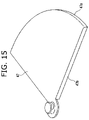
- FIGS. 14 and 15 are perspective views showing additional embodiments of the internal sealing member.
- FIG. 16 is a partial perspective view showing another embodiment of the top wall.
- FIG. 17 is a partial sectional view illustrating a can employing the top wall shown in FIG. 16 .
- FIG. 18 is a partial perspective view showing yet another embodiment of the top wall.
- FIG. 19 is a partial sectional view illustrating a can employing the top wall shown in FIG. 18 .
- FIG. 20 is a partial perspective view showing yet another embodiment of the top wall.
- FIGS. 1 to 4 are drawings showing a first embodiment of the present invention.
- a can 1 of this embodiment has a spout 3 which is opened by lifting and pulling a pull-ring 6 fixed on a top wall 2 of a can body 1 a with a rivet 5 to bend a sealing tongue portion 4 toward an inside of the can body 1 a .
- an internal sealing member 7 On a position inside the top wall 2 and away from the spout 3 , an internal sealing member 7 having a size capable of sealing the spout 3 and a fan shape with its pivot mounted to the rivet 5 is disposed in a fixed manner.
- an interlocking mechanism to rotate the internal sealing member 7 at the time when the pull-ring 6 is rotated around the rivet 5 provided is a mechanism such that a base end of the pull-ring 6 and the pivot of the internal sealing member 7 are fixed to the rivet 5 on outer and inner sides of the top wall 2 , respectively, and, after opening the spout 3 , the rivet 5 is rotatably supported on the top wall 2 .
- FIGS. 3 and 4 an opening operation of the can 1 and sealing and opening operations of the spout 3 thereafter will be described below.
- the sealing tongue portion 4 is bent toward the inside of the can body 1 a to open the spout 3 .
- contents 8 can be drunk with the mouth against the spout 3 or poured from the spout 3 .
- the rivet 5 After opening the spout 3 , the rivet 5 is rotabably supported on the top wall 2 and, as shown in FIG. 4 , by rotating the pull-ring 6 clockwise around the rivet 5 , the internal sealing member 7 is also rotated in the same direction at the same time.
- the internal sealing member 7 When the internal sealing member 7 is rotated up to a position right beneath the spout 3 , the spout 3 after opening can be sealed again.
- the sealing tongue portion 4 bent toward the inside of the can by the opening operation is being hung from a left-hand part of the rivet 5 to the inside of the can.
- the internal sealing member 7 which has a fan shape with the pivot mounted to the rivet 5 , is positioned right beneath the spout 3 to completely seal the spout 3 .
- the sealing tongue portion 4 bent toward the inside of the can functions as a stopper for the internal sealing member 7 moved to close the spout 3 , the sealing condition can be easily confirmed by rotating the internal sealing member 7 up to the position to abut against the sealing tongue portion 4 .
- the internal sealing member 7 that has closed the spout 3 as the operation described above seals the spout 3 from the inner side of the top wall 2 . Accordingly, if the can is shaken or drops, the contents 8 do not spill out. Furthermore, the spout 3 sealed by the internal sealing member 7 hinders heat exchange between the inner and outer sides of the can 1 to control a temperature change of the contents 8 of the can 1 . As a result, if the contents 8 is a cold beverage, it can be kept cold, and if the contents 8 is a hot beverage, it can be kept hot for a relatively long time.
- the contents 8 are carbonated drinks such as beer or soda
- a pressure inside the can 1 increases due to the carbon dioxide allowing the internal sealing member 7 to press itself against the spout 3 .
- the airtightness is thus increased, thereby securely resealing the spout 3 after opening.
- loss of carbon dioxide from the content 8 or the carbonated drink can be prevented.
- the pull-ring 6 is rotated around the rivet 5 counterclockwise.
- the internal sealing member 7 is also rotated in the same direction at the same time and moves to a position away from the position right beneath the spout 3 .
- the spout 3 can be easily opened. Accordingly, the spout 3 can be closed and opened simply by rotating the pull-ring 6 around the rivet 5 clockwise and counterclockwise, respectively, which makes the close/open operations extremely easy.
- the internal sealing member 7 is formed in a fan shape with the pivot mounted on the rivet 5 .
- This particular shape which does not disturb the opening operation of the spout 3 and also the closing operation even with the sealing tongue portion 4 hung from the spout 3 , enables the spout 3 to be securely resealed by an easy operation by simply rotating the pull-ring 6 .
- the internal sealing member 7 is made of substantially the same material as the material of the can body 1 a .
- the internal sealing member 7 is made of alumina base alloy.
- the internal sealing member 7 can be mounted in a process similar to a conventional process for manufacturing a can, which prevents the manufacturing process from becoming complex. Also when recycling the can 1 that has been used, it is not necessary to separate the internal sealing member 7 from the can body 1 a .
- the can body 1 a is made of steel, it is preferable to make the internal sealing member 7 of steel base alloy.
- the can 1 of the present embodiment is a cylindrical can which is commercially distributed as a can for beer or the like.
- the present invention is not restricted to the form and is applicable to any kind of can with a pull-ring (pull top, pull tab) opener regardless of the shape, size, material and content thereof.
- FIGS. 5 to 13 are drawings showing a second embodiment of the present invention.
- a can 21 of this embodiment has a spout 23 which is opened by lifting and pulling a pull-ring 26 fixed to a projection 25 formed on substantially a center of a top wall 22 of a can body 21 a to bend a sealing tongue portion 24 toward an inside of the can body 21 a .
- an internal sealing member 27 having a size capable of sealing the spout 23 and a fan shape is disposed to be fixed to the projection 25 .
- a structure for fixing the pull-ring 26 and the internal sealing member 27 to the projection 25 will be described below.
- a hat-like pre-pressed projection 25 a having an approximately semi lunar form in a plan view is formed at a substantially central position of the top wall 22 before assembly.
- a hat-like projection 27 a having an approximately semi lunar form in a plan view which is formed on a pivot of the fan-shaped internal sealing member 27 is inserted into a lower concave portion 25 c formed on a rear side of the pre-pressed projection 25 a .
- a fixing member 26 a formed in the pull-ring 26 having a substantially semi lunar-formed through hole 26 b , is mounted to an upper convex portion 25 b of the pre-pressed projection 25 a.
- the upper convex portion 25 b of the pre-pressed projection 25 a and the projection 27 a of the internal sealing member 27 are pressed. Then, as shown in FIG. 8 , the pre-pressed projection 25 a of the top wall 22 and the projection 27 a of the internal sealing member 27 are deformed to cause their diameters to be overlapping with each other. Thus, the fixing member 26 a of the pull-ring 26 and the projection 27 a of the internal sealing member 27 are fixed to the projection 25 of the top wall 22 .
- a score line 24 a and a hinge 24 b are formed so that the sealing tongue portion 24 is bent toward the inside of the can body when lifting and pulling the pull-ring 26 .
- a thin-walled portion 30 having a groove shape that is torn by a stress concentrated thereon when the pull-ring 26 is lifted and pulled is formed around the projection 25 drawing a closed circular curve surrounding the projection 25 .
- the score line 24 a is torn and the hinge portion 24 b is bent so that the sealing tongue portion 24 is bent toward the inside of the can body 21 a , thereby to open the spout 23 .
- the can is opened as shown in FIG. 11 .
- the contents of the can can be consumed with the mouth against the spout 23 or poured out through the spout 23 .
- the internal sealing member 27 which lies at a position away from the spout 23 , does not disturb the drinking or pouring out of the contents from the spout 23 .
- the circular thin-walled portion 30 surrounding the projection 25 is torn to form a gap 31 having a circular form.
- the fixing member 26 a of the pull-ring 26 and the projection 27 a of the internal sealing member 27 can be rotated free from the top wall 22 in a state integrally fixed to the projection 25 . Accordingly, when rotating the pull-ring 26 around the projection 25 with the spout 23 opened, the interlocking mechanism to rotate the internal sealing member 27 at the same time is exerted.
- the through hole 26 b in the fixing member 26 a of the pull-ring 26 , the projection 27 a of the internal sealing member 27 , and the projection 25 are mounted with their substantially semi lunar portions to be oriented in the same direction. Therefore, whenever the pull-ring 26 is rotated, the internal sealing member 27 is also rotated without idling.
- the internal sealing member 27 is rotated to the same direction at the same time, and the spout 23 after it is opened can be resealed by rotating the internal sealing member 27 up to a position right beneath the spout 26 .
- the sealing tongue portion 24 bent toward the inside of the can body 21 a by the opening operation is being hung from the hinge 24 b ( FIG. 9 ) adjacent to the projection 25 to the inside of the can body 21 a.
- the internal sealing member 27 that has closed the spout 23 as the operation described above seals the spout 23 from the inner side of the top wall 22 . Accordingly, if the can is shaken or dropped, the content will not spill out. Furthermore, the spout 23 sealed by the internal sealing member 27 hinders heat exchange between the inner and outer sides of the can 21 to control a temperature change of the content of the can 21 . As a result, a cold beverage can be kept cold while a hot beverage can be kept hot for a relatively long time.
- the content is a carbonated drink such as beer or soda
- a pressure inside the can 21 increased due to carbon dioxide allows the internal sealing member 27 to press itself against the spout 23 .
- the airtightness is thus increased, thereby securely resealing the spout 23 after opening. As a result, loss of carbon dioxide from the content or the carbonated drink can be prevented.
- the spout 23 after it is opened can be closed and opened simply by rotating the pull-ring 26 around the projection 25 clockwise and counterclockwise, respectively, which makes the close/open operations extremely easy.
- the internal sealing member 27 is formed in a fan shape with the pivot mounted on the projection 25 .
- the shape which does not disturb the closing operation even with the sealing tongue portion 24 hung from the spout 23 toward the inside of the can, enables the spout 3 to be securely resealed.
- the can body 21 a , the top wall 22 and the internal sealing member 27 that constitute the can 21 are made of alumina base alloy. Therefore, the internal sealing member 27 can be mounted in the same manufacturing process as the conventional process to manufacture a can, which does not lead to complexity in the process. Furthermore, on recycling the can 21 that has been used, it is not necessary to separate the internal sealing member 27 from the can body 21 a and other members. When the can body 21 a is made of steel, it is preferable to make the internal sealing member 27 of steel base alloy as well.
- the can 21 of the present embodiment is a cylindrical can which is commercially distributed as a can for beer or the like.
- the present invention is not restricted to this form and is widely applicable to any kind of can with a pull-ring (pull top, pull tab) opener regardless of the shape, size, material and content thereof.
- An internal sealing member 37 shown in FIG. 14 has the same form as the form of the above-described internal sealing member 27 if taken as a plan view, but is provided with a skirt 37 a extending downwardly from an arc portion of the internal sealing member 37 .
- this skirt 37 a With this skirt 37 a , the strength (rigidity) of the internal sealing member 37 is increased, and also the sealing effect of a spout is enhanced because the skirt 37 a is positioned at a corner portion where a top wall and a can body are connected.
- the configuration and function of the remaining members are the same as those of the internal sealing member 27 .
- An internal sealing member 47 shown in FIG. 15 is provided with a skirt 47 a on an arc portion thereof as well as a skirt 47 b formed along radial edges.
- top wall With reference to FIGS. 16 to 19 , additional embodiments of a top wall will be described below.
- a top wall 32 shown in FIGS. 16 an 17 is provided with a plurality of convex portions 31 projecting toward an outer surface of the top wall 32 in an area between a circular thin-walled portion 36 surrounding a projection 35 and a sealing tongue portion 34 on the top wall 32 .
- These convex portions 31 are arranged with equal intervals therebetween around the thin-walled portion 36 .
- the rigidity of the top wall 32 in the area between the thin-walled portion 36 and the sealing tongue portion 34 is increased. Accordingly, when lifting and pulling the pull-ring 26 by a normal opening operation, a stress is concentrated onto the thin-walled portion 36 to certainly break the thin-walled portion 36 that should be torn, which facilities an opening operation.
- a top wall 42 shown in FIGS. 18 and 19 is provided with a plurality of concave portions 41 extending toward an inner surface of the top wall 42 in an area between a circular thin-walled portion 46 surrounding a projection 45 and a sealing tongue portion 44 on the top wall 42 .
- These concave portions 41 are arranged with equal intervals therebetween around the thin-walled portion 46 .
- the rigidity of the top wall 42 in the area between the thin-walled portion 46 and the sealing tongue portion 44 is increased. Accordingly, when lifting and pulling the pull-ring 26 by a normal opening operation, as in the top wall 32 shown in FIGS. 16 and 17 described above, a stress is concentrated onto the thin-walled portion 46 to certainly break the thin-walled portion 46 that should be torn, which facilities an opening operation.
- the convex portions 31 of the top wall 32 shown in FIG. 16 and the concave portions 41 of the top wall 42 are substantially the same in their functions and effects.
- either of these members may be employed depending on the structures of the top walls 32 , 43 , the pull-ring 26 and the projections 35 , 45 and on the manufacturing process of the can.
- a top wall 52 shown in FIG. 20 is provided with a plurality of convex portions 51 extending toward an outer surface of the top wall 52 in an area between a circular thin-walled portion 56 surrounding a projection 55 and a sealing tongue portion 54 on the top wall 52 .
- a first group of the convex portions 51 are disposed, in a periphery of the thin-walled portion 36 , in a position on a side of the sealing tongue portion 54 .
- a second group of the convex portions 51 consisting of the same number of the first group of the convex portions 51 are disposed in symmetric relation to the first group with the projection 55 positioned at a center thereof.
- the areas where these convex portions 55 are disposed are two of the most stressed area when lifting and pulling a pull-ring (not shown) and collapsing the pull-ring after opening an spout with normal operations.
- a stress is concentrated onto the thin-walled portion 56 around the projection 55 when lifting or collapsing the pull-ring 26 to open the spout, thereby to certainly break the thin-walled portion 56 , further facilitating the opening operation.
Abstract
Description
Claims (14)
Priority Applications (2)
| Application Number | Priority Date | Filing Date | Title |
|---|---|---|---|
| PCT/JP2004/014173 WO2005051783A1 (en) | 2003-11-27 | 2004-09-28 | Can lid having re-sealing function |
| JP2005515739A JPWO2005051783A1 (en) | 2003-11-27 | 2004-09-28 | can |
Applications Claiming Priority (2)
| Application Number | Priority Date | Filing Date | Title |
|---|---|---|---|
| JP2003397585 | 2003-11-27 | ||
| JPP2003-397585 | 2003-11-27 |
Publications (2)
| Publication Number | Publication Date |
|---|---|
| US20050115969A1 US20050115969A1 (en) | 2005-06-02 |
| US7198168B2 true US7198168B2 (en) | 2007-04-03 |
Family
ID=34616539
Family Applications (1)
| Application Number | Title | Priority Date | Filing Date |
|---|---|---|---|
| US10/837,713 Expired - Fee Related US7198168B2 (en) | 2003-11-27 | 2004-05-04 | Can |
Country Status (2)
| Country | Link |
|---|---|
| US (1) | US7198168B2 (en) |
| JP (1) | JPWO2005051783A1 (en) |
Cited By (60)
| Publication number | Priority date | Publication date | Assignee | Title |
|---|---|---|---|---|
| US20070068943A1 (en) * | 2005-09-23 | 2007-03-29 | Crown Packaging Technology Inc. | Sealing device for a container |
| US20070262079A1 (en) * | 2006-05-10 | 2007-11-15 | Alexandre Paris | Opening device |
| US20080053997A1 (en) * | 2004-01-13 | 2008-03-06 | Bound2B B.V. | Device for Sealing Food Product Containers and Food Product Container Provided with such a Device |
| US20080110887A1 (en) * | 2006-10-31 | 2008-05-15 | Christopher Paul Ramsey | Resealable closure |
| US20080217347A1 (en) * | 2007-03-06 | 2008-09-11 | Viktor Markaj | Beverage container protective cover |
| US20090173737A1 (en) * | 2007-11-09 | 2009-07-09 | Crown Packaging Technology, Inc. | Resealable beverage can end and methods relating to same |
| US20090212004A1 (en) * | 2008-02-27 | 2009-08-27 | Silgan Containers Corporation | Vacuum container with protective features |
| US20090218349A1 (en) * | 2008-02-29 | 2009-09-03 | Silgan Containers Corporation | Vacuum container with protective features |
| USD607727S1 (en) | 2008-05-12 | 2010-01-12 | Silgan Containers Llc | Container |
| USD612732S1 (en) | 2008-05-12 | 2010-03-30 | Silgan Containers Llc | Container |
| USD614049S1 (en) | 2009-03-02 | 2010-04-20 | Silgan Containers Llc | Container |
| USD614969S1 (en) | 2008-05-12 | 2010-05-04 | Silgan Containers Llc | Container |
| USD614970S1 (en) | 2008-03-28 | 2010-05-04 | Silgan Containers Llc | Container |
| USD615877S1 (en) | 2009-02-05 | 2010-05-18 | Silgan Containers Llc | Container |
| USD620377S1 (en) | 2008-05-12 | 2010-07-27 | Silgan Containers Llc | Container |
| USD621724S1 (en) | 2008-04-04 | 2010-08-17 | Silgan Containers Llc | Container |
| USD624438S1 (en) | 2008-05-12 | 2010-09-28 | Silgan Containers, Llc | Container |
| USD626015S1 (en) | 2008-03-28 | 2010-10-26 | Silgan Containers Llc | Container |
| US20100294768A1 (en) * | 2009-05-22 | 2010-11-25 | Crown Packaging Technology, Inc. | resealable beverage can ends |
| USD631759S1 (en) | 2009-03-02 | 2011-02-01 | Silgan Containers Llc | Container |
| USD632190S1 (en) | 2008-03-28 | 2011-02-08 | Silgan Containers Llc | Container |
| USD632189S1 (en) | 2008-03-28 | 2011-02-08 | Silgan Containers Llc | Container |
| USD632187S1 (en) | 2008-03-28 | 2011-02-08 | Silgan Containers Llc | Container |
| USD632188S1 (en) | 2008-03-28 | 2011-02-08 | Silgan Containers Llc | Container |
| USD638311S1 (en) | 2008-05-12 | 2011-05-24 | Silgan Containers, Llc | Container |
| USD641261S1 (en) | 2008-03-28 | 2011-07-12 | Silgan Containers, Llc | Container |
| US20110233227A1 (en) * | 2006-10-31 | 2011-09-29 | Alexandre Paris | Resealable closure |
| USD649887S1 (en) | 2008-05-12 | 2011-12-06 | Silgan Containers Llc | Container |
| USD651526S1 (en) | 2009-12-29 | 2012-01-03 | Silgan Containers Llc | Container |
| USD651527S1 (en) | 2009-02-05 | 2012-01-03 | Silgan Containers Llc | Container |
| USD652741S1 (en) | 2008-04-04 | 2012-01-24 | Silgan Containers Llc | Container |
| USD652740S1 (en) | 2008-02-27 | 2012-01-24 | Silgan Containers Llc | Container |
| USD652742S1 (en) | 2008-05-12 | 2012-01-24 | Silgan Containers Llc | Container |
| USD653123S1 (en) | 2008-04-04 | 2012-01-31 | Silgan Containers Llc | Container |
| USD653125S1 (en) | 2009-09-09 | 2012-01-31 | Silgan Containers Llc | Container |
| USD653124S1 (en) | 2007-12-17 | 2012-01-31 | Silgan Containers Llc | Container |
| USD653126S1 (en) | 2009-09-30 | 2012-01-31 | Silgan Containers Llc | Container |
| USD653562S1 (en) | 2008-04-04 | 2012-02-07 | Silgan Containers Llc | Container |
| USD653563S1 (en) | 2008-04-04 | 2012-02-07 | Silgan Containers Llc | Container |
| USD656042S1 (en) | 2010-10-01 | 2012-03-20 | Silgan Containers Llc | Container |
| USD658078S1 (en) | 2010-04-30 | 2012-04-24 | Silgan Containers Llc | Container |
| US20120145712A1 (en) * | 2009-09-07 | 2012-06-14 | Xolution Gmbh | Container lid having a pressure equalizing device |
| USD671834S1 (en) | 2011-01-07 | 2012-12-04 | Ball Corporation | Closure |
| US20120312815A1 (en) * | 2009-12-09 | 2012-12-13 | Crown Packaging Technology, Inc. | Can end with film insert |
| USD672663S1 (en) | 2008-02-27 | 2012-12-18 | Silgan Containers Llc | Container |
| US20130240535A1 (en) * | 2012-03-16 | 2013-09-19 | Valon Grajqevci | Resealable Multi-Compartment Beverage Container |
| US8720717B2 (en) | 2012-02-02 | 2014-05-13 | Ball Corporation | End closure with full panel opening |
| DE102013104226A1 (en) * | 2013-04-25 | 2014-10-30 | Jürgen Sooth | Resealable can end wall, end wall unit and box |
| US9145251B2 (en) | 2012-10-26 | 2015-09-29 | Berry Plastics Corporation | Package |
| US9604769B2 (en) | 2012-03-20 | 2017-03-28 | Berry Plastics Corporation | Stand up package |
| USD787952S1 (en) | 2012-08-29 | 2017-05-30 | Ball Corporation | Contoured neck for a beverage container |
| US9901972B2 (en) | 2014-03-07 | 2018-02-27 | Ball Corporation | End closure with large opening ring pull tab |
| US20190283924A1 (en) * | 2018-03-16 | 2019-09-19 | Steven S Schuver | Resealable beverage can lid |
| US10532872B2 (en) | 2014-12-08 | 2020-01-14 | Berry Plastics Corporation | Package |
| US10632520B2 (en) | 2014-03-07 | 2020-04-28 | Ball Corporation | End closure with large opening ring pull tab |
| US10640266B2 (en) * | 2018-08-06 | 2020-05-05 | Snstech, Llc | Closure debonding system |
| US20200407109A1 (en) * | 2019-06-28 | 2020-12-31 | Florence M. Vinger | Reclosable can ends |
| US20210163175A1 (en) * | 2017-12-08 | 2021-06-03 | Seidel GmbH & Co. KG | Method for producing a liquid guidance device |
| US20220015560A1 (en) * | 2019-05-22 | 2022-01-20 | Keepcup Pty Ltd | A Beverage Cup and Closure Therefor |
| US20240034510A1 (en) * | 2022-08-01 | 2024-02-01 | Benita Ramadanovic | Soda can with closing system |
Families Citing this family (11)
| Publication number | Priority date | Publication date | Assignee | Title |
|---|---|---|---|---|
| AT507950B1 (en) * | 2009-02-23 | 2011-07-15 | Xolution Gmbh | COVER OF A CONTAINER |
| US9637269B1 (en) | 2012-08-10 | 2017-05-02 | Daniel A. Zabaleta | Resealable container lid and accessories including methods of manufacturing and use |
| US10968010B1 (en) | 2012-08-10 | 2021-04-06 | Daniel A Zabaleta | Resealable container lid and accessories including methods of manufacture and use |
| US8844761B2 (en) | 2012-08-10 | 2014-09-30 | Daniel A. Zabaleta | Resealable beverage containers and methods of making same |
| USD795693S1 (en) | 2012-08-10 | 2017-08-29 | Daniel A Zabeleta | Axially oriented peripheral sidewalled beverage container lid |
| US8985371B2 (en) | 2012-08-10 | 2015-03-24 | Daniel A. Zabaleta | Resealable beverage containers and methods of making same |
| USD828753S1 (en) | 2012-08-10 | 2018-09-18 | Daniel A Zabaleta | Axially oriented peripheral sidewalled beverage container lid |
| CN102795399B (en) * | 2012-08-24 | 2015-04-08 | 陈其昌 | Cover part for bottleneck |
| CN104828361A (en) * | 2015-05-15 | 2015-08-12 | 张运 | Portable dustproof zip-top can |
| WO2020139429A1 (en) * | 2018-11-09 | 2020-07-02 | Schuver Steven S | Resealable beverage can lid |
| HUP2100352A1 (en) * | 2021-10-12 | 2023-04-28 | Tamas Nagel | Resealable can lid for drink cans |
Citations (17)
| Publication number | Priority date | Publication date | Assignee | Title |
|---|---|---|---|---|
| US1180913A (en) * | 1915-02-26 | 1916-04-25 | Charles H Foss | Can-closure. |
| US4537326A (en) * | 1983-12-13 | 1985-08-27 | Morehead Clyde D | Protector for drink opening |
| US4681238A (en) * | 1986-10-03 | 1987-07-21 | Sanchez Ruben G | Re-closure device for pop top containers |
| US4834258A (en) * | 1987-10-08 | 1989-05-30 | Root Charles E | Can closure |
| JPH057632A (en) | 1991-02-26 | 1993-01-19 | Komax Syst Inc | Bubble srrinkling device |
| US5379914A (en) * | 1993-11-29 | 1995-01-10 | Martins; Alvaro F. | Filter for drinking container |
| JPH08104327A (en) | 1994-10-04 | 1996-04-23 | Akira Kono | Can with back lid |
| JPH08244770A (en) | 1995-03-09 | 1996-09-24 | Takako Yamamoto | Can cover capable of sealing discharge opening |
| JPH08318944A (en) | 1995-05-22 | 1996-12-03 | Teruo Ozaki | Pull-top can |
| US5617920A (en) * | 1992-08-31 | 1997-04-08 | Union Oil Company Of California | Method for modifying gelation time of organically crosslinked, aqueous gels |
| US5775534A (en) * | 1995-11-24 | 1998-07-07 | Webb; Michael Reginald | Beverage container having filtered opening |
| US5845801A (en) * | 1997-12-09 | 1998-12-08 | Heitl; Thomas L. | Safety shield for pop top beverage containers |
| US20010032852A1 (en) * | 2000-02-07 | 2001-10-25 | Naude Johannes Jurgens | Beverage container fitted with supplementary closure means |
| US6588617B1 (en) * | 2002-01-21 | 2003-07-08 | Marjan Majcen | Rotative closure for beverage containers |
| US6626314B1 (en) * | 2001-03-13 | 2003-09-30 | Rexam Beverage Can Company | Resealable closure for beverage container |
| US6755315B1 (en) * | 1999-08-17 | 2004-06-29 | Rainer Jonscher | Beverage can with sieve cap |
| US20050051553A1 (en) * | 2003-09-04 | 2005-03-10 | Rung-Feng Li | Re-closure device for pop-top can |
Family Cites Families (5)
| Publication number | Priority date | Publication date | Assignee | Title |
|---|---|---|---|---|
| US4951835A (en) * | 1990-01-16 | 1990-08-28 | Demars Robert A | Beverage container opening and resealing device |
| JP3006757U (en) * | 1994-05-12 | 1995-01-31 | ファー チョン シェ | Pull picking in pool open can |
| JP3027910U (en) * | 1996-02-13 | 1996-08-20 | 日本プライズ産業株式会社 | Beverage cans and beverage containers |
| JP3052836U (en) * | 1998-03-31 | 1998-10-09 | 啓予 太田 | Can openable container |
| JP2003237779A (en) * | 2002-02-15 | 2003-08-27 | Toyo Seikan Kaisha Ltd | Easily openable lid having re-sealing function |
-
2004
- 2004-05-04 US US10/837,713 patent/US7198168B2/en not_active Expired - Fee Related
- 2004-09-28 JP JP2005515739A patent/JPWO2005051783A1/en not_active Ceased
Patent Citations (18)
| Publication number | Priority date | Publication date | Assignee | Title |
|---|---|---|---|---|
| US1180913A (en) * | 1915-02-26 | 1916-04-25 | Charles H Foss | Can-closure. |
| US4537326A (en) * | 1983-12-13 | 1985-08-27 | Morehead Clyde D | Protector for drink opening |
| US4681238A (en) * | 1986-10-03 | 1987-07-21 | Sanchez Ruben G | Re-closure device for pop top containers |
| US4834258A (en) * | 1987-10-08 | 1989-05-30 | Root Charles E | Can closure |
| JPH057632A (en) | 1991-02-26 | 1993-01-19 | Komax Syst Inc | Bubble srrinkling device |
| US5617920A (en) * | 1992-08-31 | 1997-04-08 | Union Oil Company Of California | Method for modifying gelation time of organically crosslinked, aqueous gels |
| US5379914A (en) * | 1993-11-29 | 1995-01-10 | Martins; Alvaro F. | Filter for drinking container |
| JPH08104327A (en) | 1994-10-04 | 1996-04-23 | Akira Kono | Can with back lid |
| JPH08244770A (en) | 1995-03-09 | 1996-09-24 | Takako Yamamoto | Can cover capable of sealing discharge opening |
| JPH08318944A (en) | 1995-05-22 | 1996-12-03 | Teruo Ozaki | Pull-top can |
| US5775534A (en) * | 1995-11-24 | 1998-07-07 | Webb; Michael Reginald | Beverage container having filtered opening |
| US5775534C1 (en) * | 1995-11-24 | 2001-01-02 | Michael Reginald Webb | Beverage container having filtered opening |
| US5845801A (en) * | 1997-12-09 | 1998-12-08 | Heitl; Thomas L. | Safety shield for pop top beverage containers |
| US6755315B1 (en) * | 1999-08-17 | 2004-06-29 | Rainer Jonscher | Beverage can with sieve cap |
| US20010032852A1 (en) * | 2000-02-07 | 2001-10-25 | Naude Johannes Jurgens | Beverage container fitted with supplementary closure means |
| US6626314B1 (en) * | 2001-03-13 | 2003-09-30 | Rexam Beverage Can Company | Resealable closure for beverage container |
| US6588617B1 (en) * | 2002-01-21 | 2003-07-08 | Marjan Majcen | Rotative closure for beverage containers |
| US20050051553A1 (en) * | 2003-09-04 | 2005-03-10 | Rung-Feng Li | Re-closure device for pop-top can |
Cited By (85)
| Publication number | Priority date | Publication date | Assignee | Title |
|---|---|---|---|---|
| US20080053997A1 (en) * | 2004-01-13 | 2008-03-06 | Bound2B B.V. | Device for Sealing Food Product Containers and Food Product Container Provided with such a Device |
| US7819280B2 (en) * | 2004-01-13 | 2010-10-26 | Bound2B B.V. | Device for sealing food product containers and food product container provided with such a device |
| US8336725B2 (en) | 2005-09-23 | 2012-12-25 | Crown Packaging Technology, Inc. | Sealing device for a container |
| US20070068943A1 (en) * | 2005-09-23 | 2007-03-29 | Crown Packaging Technology Inc. | Sealing device for a container |
| US20070262079A1 (en) * | 2006-05-10 | 2007-11-15 | Alexandre Paris | Opening device |
| US20090179033A1 (en) * | 2006-05-10 | 2009-07-16 | Crown Packaging Technology , Inc. | Can opening device |
| US7918359B2 (en) * | 2006-05-10 | 2011-04-05 | Crown, Packaging Technology, Inc. | Opening device |
| US20080110887A1 (en) * | 2006-10-31 | 2008-05-15 | Christopher Paul Ramsey | Resealable closure |
| US20110233227A1 (en) * | 2006-10-31 | 2011-09-29 | Alexandre Paris | Resealable closure |
| US8240498B2 (en) | 2006-10-31 | 2012-08-14 | Crown Packaging Technology, Inc. | Resealable closure |
| US20080217347A1 (en) * | 2007-03-06 | 2008-09-11 | Viktor Markaj | Beverage container protective cover |
| US20090173737A1 (en) * | 2007-11-09 | 2009-07-09 | Crown Packaging Technology, Inc. | Resealable beverage can end and methods relating to same |
| US8336726B2 (en) | 2007-11-09 | 2012-12-25 | Crown Packaging Technology, Inc. | Resealable beverage can end and methods relating to same |
| US8931656B2 (en) | 2007-11-09 | 2015-01-13 | Crown Packaging Technology, Inc. | Resealable beverage can end and methods relating to same |
| USD653124S1 (en) | 2007-12-17 | 2012-01-31 | Silgan Containers Llc | Container |
| USD672663S1 (en) | 2008-02-27 | 2012-12-18 | Silgan Containers Llc | Container |
| US9216840B2 (en) | 2008-02-27 | 2015-12-22 | Silgan Containers Llc | Vacuum container with protective features |
| USD652740S1 (en) | 2008-02-27 | 2012-01-24 | Silgan Containers Llc | Container |
| US8141741B2 (en) | 2008-02-27 | 2012-03-27 | Silgan Containers Llc | Vacuum container with protective features |
| US20090212004A1 (en) * | 2008-02-27 | 2009-08-27 | Silgan Containers Corporation | Vacuum container with protective features |
| US20090218349A1 (en) * | 2008-02-29 | 2009-09-03 | Silgan Containers Corporation | Vacuum container with protective features |
| USD632190S1 (en) | 2008-03-28 | 2011-02-08 | Silgan Containers Llc | Container |
| USD632189S1 (en) | 2008-03-28 | 2011-02-08 | Silgan Containers Llc | Container |
| USD632187S1 (en) | 2008-03-28 | 2011-02-08 | Silgan Containers Llc | Container |
| USD632188S1 (en) | 2008-03-28 | 2011-02-08 | Silgan Containers Llc | Container |
| USD626015S1 (en) | 2008-03-28 | 2010-10-26 | Silgan Containers Llc | Container |
| USD641261S1 (en) | 2008-03-28 | 2011-07-12 | Silgan Containers, Llc | Container |
| USD614970S1 (en) | 2008-03-28 | 2010-05-04 | Silgan Containers Llc | Container |
| USD663622S1 (en) | 2008-03-28 | 2012-07-17 | Silgan Containers Llc | Container |
| USD653123S1 (en) | 2008-04-04 | 2012-01-31 | Silgan Containers Llc | Container |
| USD653563S1 (en) | 2008-04-04 | 2012-02-07 | Silgan Containers Llc | Container |
| USD653562S1 (en) | 2008-04-04 | 2012-02-07 | Silgan Containers Llc | Container |
| USD621724S1 (en) | 2008-04-04 | 2010-08-17 | Silgan Containers Llc | Container |
| USD652741S1 (en) | 2008-04-04 | 2012-01-24 | Silgan Containers Llc | Container |
| USD638311S1 (en) | 2008-05-12 | 2011-05-24 | Silgan Containers, Llc | Container |
| USD652742S1 (en) | 2008-05-12 | 2012-01-24 | Silgan Containers Llc | Container |
| USD620377S1 (en) | 2008-05-12 | 2010-07-27 | Silgan Containers Llc | Container |
| USD607727S1 (en) | 2008-05-12 | 2010-01-12 | Silgan Containers Llc | Container |
| USD649887S1 (en) | 2008-05-12 | 2011-12-06 | Silgan Containers Llc | Container |
| USD614969S1 (en) | 2008-05-12 | 2010-05-04 | Silgan Containers Llc | Container |
| USD624438S1 (en) | 2008-05-12 | 2010-09-28 | Silgan Containers, Llc | Container |
| USD612732S1 (en) | 2008-05-12 | 2010-03-30 | Silgan Containers Llc | Container |
| USD651527S1 (en) | 2009-02-05 | 2012-01-03 | Silgan Containers Llc | Container |
| USD615877S1 (en) | 2009-02-05 | 2010-05-18 | Silgan Containers Llc | Container |
| USD631759S1 (en) | 2009-03-02 | 2011-02-01 | Silgan Containers Llc | Container |
| USD663210S1 (en) | 2009-03-02 | 2012-07-10 | Silgan Containers Llc | Container |
| USD614049S1 (en) | 2009-03-02 | 2010-04-20 | Silgan Containers Llc | Container |
| US20100294768A1 (en) * | 2009-05-22 | 2010-11-25 | Crown Packaging Technology, Inc. | resealable beverage can ends |
| US8833585B2 (en) | 2009-05-22 | 2014-09-16 | Crown Packaging Technology, Inc. | Resealable beverage can ends |
| US20120145712A1 (en) * | 2009-09-07 | 2012-06-14 | Xolution Gmbh | Container lid having a pressure equalizing device |
| US8794469B2 (en) * | 2009-09-07 | 2014-08-05 | Xolution Gmbh | Container lid having a pressure equalizing device |
| USD653125S1 (en) | 2009-09-09 | 2012-01-31 | Silgan Containers Llc | Container |
| USD661204S1 (en) | 2009-09-09 | 2012-06-05 | Silgan Containers Llc | Container |
| USD677585S1 (en) | 2009-09-09 | 2013-03-12 | Silgan Containers Llc | Container |
| USD661203S1 (en) | 2009-09-30 | 2012-06-05 | Silgan Containers Llc | Container |
| USD653126S1 (en) | 2009-09-30 | 2012-01-31 | Silgan Containers Llc | Container |
| USD677584S1 (en) | 2009-09-30 | 2013-03-12 | Silgan Containers Llc | Container |
| US8998028B2 (en) * | 2009-12-09 | 2015-04-07 | Crown Packaging Technology, Inc. | Can end with film insert |
| US20120312815A1 (en) * | 2009-12-09 | 2012-12-13 | Crown Packaging Technology, Inc. | Can end with film insert |
| USD651526S1 (en) | 2009-12-29 | 2012-01-03 | Silgan Containers Llc | Container |
| USD658078S1 (en) | 2010-04-30 | 2012-04-24 | Silgan Containers Llc | Container |
| USD656042S1 (en) | 2010-10-01 | 2012-03-20 | Silgan Containers Llc | Container |
| USD671834S1 (en) | 2011-01-07 | 2012-12-04 | Ball Corporation | Closure |
| US8720717B2 (en) | 2012-02-02 | 2014-05-13 | Ball Corporation | End closure with full panel opening |
| US20130240535A1 (en) * | 2012-03-16 | 2013-09-19 | Valon Grajqevci | Resealable Multi-Compartment Beverage Container |
| US8875926B2 (en) * | 2012-03-16 | 2014-11-04 | Valon Grajqevci | Resealable multi-compartment beverage container |
| US9604769B2 (en) | 2012-03-20 | 2017-03-28 | Berry Plastics Corporation | Stand up package |
| USD870567S1 (en) | 2012-08-29 | 2019-12-24 | Ball Corporation | Contoured neck for a beverage container |
| USD787952S1 (en) | 2012-08-29 | 2017-05-30 | Ball Corporation | Contoured neck for a beverage container |
| US9145251B2 (en) | 2012-10-26 | 2015-09-29 | Berry Plastics Corporation | Package |
| US9884716B2 (en) | 2012-10-26 | 2018-02-06 | Berry Plastics Corporation | Package |
| DE102013104226B4 (en) * | 2013-04-25 | 2015-09-10 | Jürgen Sooth | Resealable can end wall, end wall unit and box |
| DE102013104226A1 (en) * | 2013-04-25 | 2014-10-30 | Jürgen Sooth | Resealable can end wall, end wall unit and box |
| US9901972B2 (en) | 2014-03-07 | 2018-02-27 | Ball Corporation | End closure with large opening ring pull tab |
| US10632520B2 (en) | 2014-03-07 | 2020-04-28 | Ball Corporation | End closure with large opening ring pull tab |
| US10532872B2 (en) | 2014-12-08 | 2020-01-14 | Berry Plastics Corporation | Package |
| US20210163175A1 (en) * | 2017-12-08 | 2021-06-03 | Seidel GmbH & Co. KG | Method for producing a liquid guidance device |
| US20190283924A1 (en) * | 2018-03-16 | 2019-09-19 | Steven S Schuver | Resealable beverage can lid |
| US10562664B2 (en) * | 2018-03-16 | 2020-02-18 | Steven S Schuver | Resealable beverage can lid |
| US10640266B2 (en) * | 2018-08-06 | 2020-05-05 | Snstech, Llc | Closure debonding system |
| US20220015560A1 (en) * | 2019-05-22 | 2022-01-20 | Keepcup Pty Ltd | A Beverage Cup and Closure Therefor |
| US11793337B2 (en) * | 2019-05-22 | 2023-10-24 | Keepcup Pty Ltd | Beverage cup and closure therefor |
| US20200407109A1 (en) * | 2019-06-28 | 2020-12-31 | Florence M. Vinger | Reclosable can ends |
| US11661233B2 (en) * | 2019-06-28 | 2023-05-30 | Florence M Vinger | Reclosable can ends |
| US20240034510A1 (en) * | 2022-08-01 | 2024-02-01 | Benita Ramadanovic | Soda can with closing system |
Also Published As
| Publication number | Publication date |
|---|---|
| JPWO2005051783A1 (en) | 2007-06-21 |
| US20050115969A1 (en) | 2005-06-02 |
Similar Documents
| Publication | Publication Date | Title |
|---|---|---|
| US7198168B2 (en) | Can | |
| JP5542432B2 (en) | Can opener | |
| US4821912A (en) | Reclosable self-opening can end | |
| US8931656B2 (en) | Resealable beverage can end and methods relating to same | |
| RU2286932C2 (en) | Repeatedly sealable capping device for open end of beverage container | |
| US8336725B2 (en) | Sealing device for a container | |
| US4077538A (en) | Vendable reclosable beverage container | |
| US6739471B2 (en) | Container with rotary closure | |
| US20070164026A1 (en) | Automatic opening, venting, and closing re-sealable container closure | |
| US8215513B1 (en) | Self-closing resealable can end | |
| US7891517B2 (en) | Apparatus for sealing a beverage can | |
| US20080272120A1 (en) | Rupture Type Openable Beverage Container Lid | |
| US9845179B2 (en) | Gas tight resealable can end for beverage containers | |
| US10611515B2 (en) | Resealable beverage can lid | |
| WO2005051783A1 (en) | Can lid having re-sealing function | |
| US20240034510A1 (en) | Soda can with closing system | |
| GB2258208A (en) | Resealable lid for drinks can. | |
| JP2575691Y2 (en) | Can body lid | |
| WO2011090454A1 (en) | Double ended openers beverage can | |
| JPH09188346A (en) | Pouring port for liquid container | |
| WO2020139429A1 (en) | Resealable beverage can lid | |
| JPH11310234A (en) | Lid | |
| GB2278335A (en) | Resealable easy-open can | |
| JP2000053131A (en) | Lid body | |
| GB2342917A (en) | Can sealer |
Legal Events
| Date | Code | Title | Description |
|---|---|---|---|
| AS | Assignment |
Owner name: MIZUMA, JYUNZI, JAPAN Free format text: ASSIGNMENT OF ASSIGNORS INTEREST;ASSIGNOR:MIZUMA, JYUNZI;REEL/FRAME:015296/0564 Effective date: 20040427 Owner name: FUNATU, HIROSI, JAPAN Free format text: ASSIGNMENT OF ASSIGNORS INTEREST;ASSIGNOR:MIZUMA, JYUNZI;REEL/FRAME:015296/0564 Effective date: 20040427 Owner name: NAKAO, YUTAKA, JAPAN Free format text: ASSIGNMENT OF ASSIGNORS INTEREST;ASSIGNOR:MIZUMA, JYUNZI;REEL/FRAME:015296/0564 Effective date: 20040427 Owner name: KOMATSU, YOSHITO, JAPAN Free format text: ASSIGNMENT OF ASSIGNORS INTEREST;ASSIGNOR:MIZUMA, JYUNZI;REEL/FRAME:015296/0564 Effective date: 20040427 Owner name: TANAKA, KOICHI, JAPAN Free format text: ASSIGNMENT OF ASSIGNORS INTEREST;ASSIGNOR:MIZUMA, JYUNZI;REEL/FRAME:015296/0564 Effective date: 20040427 Owner name: SHINOHARA, KENICHI, JAPAN Free format text: ASSIGNMENT OF ASSIGNORS INTEREST;ASSIGNOR:MIZUMA, JYUNZI;REEL/FRAME:015296/0564 Effective date: 20040427 |
|
| REMI | Maintenance fee reminder mailed | ||
| LAPS | Lapse for failure to pay maintenance fees | ||
| STCH | Information on status: patent discontinuation |
Free format text: PATENT EXPIRED DUE TO NONPAYMENT OF MAINTENANCE FEES UNDER 37 CFR 1.362 |
|
| FP | Expired due to failure to pay maintenance fee |
Effective date: 20110403 |