US7170299B1 - Electronic fuse blow mimic and methods for adjusting electronic fuse blow - Google Patents
Electronic fuse blow mimic and methods for adjusting electronic fuse blow Download PDFInfo
- Publication number
- US7170299B1 US7170299B1 US11/276,120 US27612006A US7170299B1 US 7170299 B1 US7170299 B1 US 7170299B1 US 27612006 A US27612006 A US 27612006A US 7170299 B1 US7170299 B1 US 7170299B1
- Authority
- US
- United States
- Prior art keywords
- fuse
- blow
- current
- nfet
- fuse blow
- Prior art date
- Legal status (The legal status is an assumption and is not a legal conclusion. Google has not performed a legal analysis and makes no representation as to the accuracy of the status listed.)
- Expired - Fee Related
Links
Images


Classifications
-
- G—PHYSICS
- G11—INFORMATION STORAGE
- G11C—STATIC STORES
- G11C17/00—Read-only memories programmable only once; Semi-permanent stores, e.g. manually-replaceable information cards
- G11C17/14—Read-only memories programmable only once; Semi-permanent stores, e.g. manually-replaceable information cards in which contents are determined by selectively establishing, breaking or modifying connecting links by permanently altering the state of coupling elements, e.g. PROM
- G11C17/16—Read-only memories programmable only once; Semi-permanent stores, e.g. manually-replaceable information cards in which contents are determined by selectively establishing, breaking or modifying connecting links by permanently altering the state of coupling elements, e.g. PROM using electrically-fusible links
- G11C17/165—Memory cells which are electrically programmed to cause a change in resistance, e.g. to permit multiple resistance steps to be programmed rather than conduct to or from non-conduct change of fuses and antifuses
-
- G—PHYSICS
- G11—INFORMATION STORAGE
- G11C—STATIC STORES
- G11C17/00—Read-only memories programmable only once; Semi-permanent stores, e.g. manually-replaceable information cards
- G11C17/14—Read-only memories programmable only once; Semi-permanent stores, e.g. manually-replaceable information cards in which contents are determined by selectively establishing, breaking or modifying connecting links by permanently altering the state of coupling elements, e.g. PROM
- G11C17/18—Auxiliary circuits, e.g. for writing into memory
-
- G—PHYSICS
- G11—INFORMATION STORAGE
- G11C—STATIC STORES
- G11C29/00—Checking stores for correct operation ; Subsequent repair; Testing stores during standby or offline operation
- G11C29/02—Detection or location of defective auxiliary circuits, e.g. defective refresh counters
-
- G—PHYSICS
- G11—INFORMATION STORAGE
- G11C—STATIC STORES
- G11C29/00—Checking stores for correct operation ; Subsequent repair; Testing stores during standby or offline operation
- G11C29/02—Detection or location of defective auxiliary circuits, e.g. defective refresh counters
- G11C29/027—Detection or location of defective auxiliary circuits, e.g. defective refresh counters in fuses
-
- G—PHYSICS
- G11—INFORMATION STORAGE
- G11C—STATIC STORES
- G11C29/00—Checking stores for correct operation ; Subsequent repair; Testing stores during standby or offline operation
- G11C29/02—Detection or location of defective auxiliary circuits, e.g. defective refresh counters
- G11C29/028—Detection or location of defective auxiliary circuits, e.g. defective refresh counters with adaption or trimming of parameters
-
- G—PHYSICS
- G01—MEASURING; TESTING
- G01R—MEASURING ELECTRIC VARIABLES; MEASURING MAGNETIC VARIABLES
- G01R31/00—Arrangements for testing electric properties; Arrangements for locating electric faults; Arrangements for electrical testing characterised by what is being tested not provided for elsewhere
- G01R31/50—Testing of electric apparatus, lines, cables or components for short-circuits, continuity, leakage current or incorrect line connections
- G01R31/74—Testing of fuses
-
- H—ELECTRICITY
- H01—ELECTRIC ELEMENTS
- H01L—SEMICONDUCTOR DEVICES NOT COVERED BY CLASS H10
- H01L23/00—Details of semiconductor or other solid state devices
- H01L23/52—Arrangements for conducting electric current within the device in operation from one component to another, i.e. interconnections, e.g. wires, lead frames
- H01L23/522—Arrangements for conducting electric current within the device in operation from one component to another, i.e. interconnections, e.g. wires, lead frames including external interconnections consisting of a multilayer structure of conductive and insulating layers inseparably formed on the semiconductor body
- H01L23/525—Arrangements for conducting electric current within the device in operation from one component to another, i.e. interconnections, e.g. wires, lead frames including external interconnections consisting of a multilayer structure of conductive and insulating layers inseparably formed on the semiconductor body with adaptable interconnections
- H01L23/5256—Arrangements for conducting electric current within the device in operation from one component to another, i.e. interconnections, e.g. wires, lead frames including external interconnections consisting of a multilayer structure of conductive and insulating layers inseparably formed on the semiconductor body with adaptable interconnections comprising fuses, i.e. connections having their state changed from conductive to non-conductive
-
- H—ELECTRICITY
- H01—ELECTRIC ELEMENTS
- H01L—SEMICONDUCTOR DEVICES NOT COVERED BY CLASS H10
- H01L2924/00—Indexing scheme for arrangements or methods for connecting or disconnecting semiconductor or solid-state bodies as covered by H01L24/00
- H01L2924/0001—Technical content checked by a classifier
- H01L2924/0002—Not covered by any one of groups H01L24/00, H01L24/00 and H01L2224/00
Definitions
- the invention relates generally to electronic fuse blow, and more particularly, to a method and system for mimicking an electronic fuse blow and adjusting the same.
- An electronic fuse is basically a poly silicon fuse link which is coupled to a voltage line (usually referred to as a FSource) on one end, and to the top of an n-channel field-effect transistor (NFET) on the other end.
- FIG. 1 shows a configuration of an electronic fuse 10 including a poly silicon fuse link 12 and an NFET 14 .
- NFET 14 of fuse 10 is usually referred to as a blowFET 14 .
- the gate of blowFET 14 is coupled to a gate voltage 24 .
- a voltage is supplied by the FSource and NFET 14 is turned on by, inter alia, a gate voltage (Vdd or blow Vdd) 24 , for a particular amount of time, which allows controlled electromigration to occur, which causes a salicide/boron pile-up on an anode side (not shown) of poly fuse link 12 .
- the resistance across poly fuse link 12 may rise from hundreds of ohms to many Kilo-ohms.
- the fuse resistance rise during a fuse blow needs to meet a particular chip characteristic requirement.
- Using a “one size fits all” approach to a fuse blow will probably result in two undesirable results, i.e., ruptured fuse or weak fuse blow.
- the fuse blow process may need to be altered to provide the desired fuse yield. That is, the environmental variables of a fuse blow process, e.g., blow Vdd 24 , FSource voltage, or the fuse blow time, may need to be varied according to a different characteristic requirement of the chip.
- blow Vdd 24 blow Vdd 24
- FSource voltage or the fuse blow time
- a system, method and program product for adjusting an environmental variable of a fuse blow of an electronic fuse are disclosed.
- a mimic NFET is coupled to a fuse blow source voltage line, a fuse blow gate voltage line, and a chip ground in the same manner as the electronic fuse, except that the mimic NFET is not attached to a poly fuse link.
- the on current (ion) and off current (ioff) of the mimic NFET are measured to determine a blow current of the electronic fuse.
- the environmental variable is adjusted based on the determined blow current.
- a first aspect of the invention provides a method for adjusting a fuse blow environmental variable of an electronic fuse on an integrated circuit chip, the electronic fuse including a poly silicon fuse link and a blow n-channel field-effect transistor (NFET) attached to each other, the method comprising: providing the electronic fuse, the electronic fuse being coupled to a fuse blow source voltage line, a fuse blow gate voltage line, and a chip ground; coupling a mimic NFET to the fuse blow source voltage line, the fuse blow gate voltage line, and the chip ground in same manner as the electronic fuse, except that the mimic NFET is not attached to a poly silicon fuse link; measuring an on current (ion) and an off current (ioff) of the mimic NFET under a preset value of the fuse blow environmental variable; determining a fuse blow current of the electronic fuse under the preset value of the fuse blow environmental variable based on a difference between the measured on current (ion) and off current (ioff) of the mimic NFET; and adjusting the preset value of the environmental variable based on the determined fuse
- a second aspect of the invention provides a computer program product for adjusting a fuse blow environmental variable of an electronic fuse on an integrated circuit chip, the electronic fuse including a poly silicon fuse link and a blow n-channel field-effect transistor (NFET) attached to each other, and the electronic fuse being coupled to a fuse blow source voltage line, a fuse blow gate voltage line, and a chip ground
- the computer program product comprising: computer usable program code configured to: control measuring an on current (ion) and an off current (ioff) of a mimic NFET under a preset value of a fuse blow environmental variable, the mimic NFET being coupled to the fuse blow source voltage line, the fuse blow gate voltage line, and the chip ground in same manner as the electronic fuse, except that the mimic NFET is not attached to a poly silicon fuse link; determine a fuse blow current of the electronic fuse under the preset value of the fuse blow environmental variable based on a difference between the measured on current (ion) and off current (ioff) of the mimic NFET; and determine an adjustment of the prese
- a third aspect of the invention provides a system for dynamically adjusting a fuse blow environmental variable of an electronic fuse on an integrated circuit chip, the electronic fuse including a poly silicon fuse link and a blow n-channel field-effect transistor (NFET) attached to each other, and the electronic fuse being coupled to a fuse blow source voltage line, a fuse blow gate voltage line, and a chip ground, the system comprising: a measurer for measuring an on current (ion) and an off current (ioff) of a mimic NFET under a preset value of a fuse blow environmental variable, the mimic NFET being coupled to the fuse blow source voltage line, the fuse blow gate voltage line, and the chip ground in same manner as the electronic fuse, except that the mimic NFET is not attached to a poly fuse link; a determinator for determining a fuse blow current of the electronic fuse under the preset value of the fuse blow environmental variable based on a difference between the measured on current (ion) and off current (ioff) of the mimic NFET; and an adjuster for adjusting the
- FIG. 1 shows a configuration of an electronic fuse according to prior art.
- FIG. 2 shows an illustrative embodiment of a hardware implementation system for mimicking an electronic fuse blow according to the invention.
- FIG. 3 shows a flow diagram of mimicking and adjusting a fuse blow of an electronic fuse using the hardware implementation of FIG. 2 according to the invention.
- FIG. 4 shows a block diagram of an illustrative computer system according to the invention.
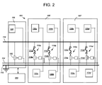
- FIG. 2 shows an illustrative embodiment of a hardware implementation system 100 for mimicking an electronic fuse blow.
- an application specific integrated circuit may include, among other components, an electronic chip identification (ECID) macro which contains electronic fuses.
- the ASIC may also include electronic fuses present for the purpose of implementing certain redundancy structures, such as structures commonly found in memory arrays (i.e. redundant wordlines or redundant columns). The fuses may be blown to disconnect a normal wordline and replace it with a redundant wordline if, for example, the normal wordline is detected as defective.
- ECID electronic chip identification
- implementation system 100 includes electronic fuses ( 110 a and 110 b ) within an ECID macro 105 , and electronic fuses ( 110 c and 110 d ) within a redundancy fuse bay 107 of an integrated circuit chip (not shown), for illustrative purpose only.
- Each fuse ( 110 a – 110 d ) includes a poly silicon fuse link, 112 a – 112 d , respectively and a blowFET 114 a – 114 d respectively.
- blowFETs 114 are of the same size. However this may not be necessary in all cases.
- Each fuse 110 is coupled between a FSource 116 and a chip ground 118 .
- FSource 116 provides a fuse blow source voltage (hereinafter, FSource voltage).
- the blowFETs 114 a – 114 d are controlled by scan-able or otherwise controllable latches 120 a – 120 d and 122 a – 122 d , respectively, to enable or disable fuses 110 . It is understood that any now known and later developed methods for enabling and disabling fuses 110 are also included in the current invention. Specifically, when the latches 120 and 122 are set low, blowFETs 114 are de-selected and fuses 110 are disabled. BlowFETs 114 are also coupled to a blow enable line 124 , which provides a fuse blow gate voltage (hereinafter, blow Vdd) to the gates of blowFETs 114 . It is understood that ECID 105 and redundant fuse bay 107 are used for illustration only and are not meant to limit the scope and the current invention, and the current invention can be used with respect to all fuses on a chip.
- blow Vdd fuse blow gate voltage
- implementation system 100 includes a test device 130 including an n-channel field-effect transistor (NFET) 132 (herein after “mimic FET”) 132 and a controllable latch 134 , Controllable latch 134 is coupled to the gate of mimic FET 132 to control mimic FET 132 .
- controllable latch 134 will be referred to as a mimic enable latch 134 , for descriptive purposes only.
- mimic FET 132 is of the same size as blowFETs 114 .
- mimic FET 132 may be of different size than blowFET 114 , as will be described later, Mimic FET 132 is coupled between FSource 116 and ground 118 and is coupled to blow enable line 124 (providing blow Vdd) in the same manner as fuses 110 including blowFETs 114 , except that mimic FET 132 is built into the chip without a poly silicon fuse link attached. It is understood that test device 130 may be built into the chip or may be attached to the chip. Test device 130 may also be responsive to a computer system 200 (see FIG. 4 for details) that controls the operation of, inter alia, test device 130 .
- FIG. 3 shows a flow diagram of a method of mimicking and adjusting a fuse blow of electronic fuses 110 using implementation system 100 of FIG. 2 .
- step S 201 fuse blows of fuses 110 are mimicked using mimic FET 132 .
- blowFETs 114 of fuses 110 are disabled through, e.g., a chip scan.
- controllable latches 120 and 122 are set low through the chip scan.
- step S 201 a an off current (ioff) of mimic FET 132 is measured.
- FSource 116 and blow enable line 124 are held high, with a FSource 116 voltage and a blow Vdd of blow enable line 124 both being set the same as their respective preset values to be used during the fuse blow, for example, 3.30V and 1.35V for FSource 116 voltage and the blow Vdd, respectively.
- a current through mimic FET 132 is measured. This current is the off current (ioff) of mimic FET 132 .
- step S 201 b an on current (ion) of mimic FET 132 is measured.
- mimic enable latch 134 is set high through, e.g., a chip scan, which turns on mimic FET 132 , with FSource 116 and blow enable line 124 still on. The current through mimic FET 132 , i.e., on current (ion), is then measured.
- the fuse blow current (iBLOW) for fuses 110 (under blow Vdd of, e.g., 1.35V) is determined based on the difference between the measured on current (ion) and off current (ioff) of mimic FET 132 . If mimic FET 132 is of exactly the same size as blowFETs 114 , the difference between the measured on current (ion) and off current (ioff) of mimic FET 132 is the iBLOW for fuses 110 . If mimic FET 132 is of different size than blowFETs 114 , the difference between the measured on current (ion) and off current (ioff) of mimic FET 132 may be converted into iBLOW using now known or later developed methods.
- an environmental variable of the fuse blow for example, blow Vdd provided by blow enable line 124
- blow Vdd provided by blow enable line 124
- a three-way decision may be performed. Specifically, an upper level threshold, for example, 14 mA, and a lower level threshold, for example, 10 mA, are set for the determined iBLOW. If the determined iBLOW is higher than the upper level threshold, here 14 mA, the blow Vdd provided by blow enable line 124 may be decreased, for example, from the preset 1.35V to 1.20V.
- the blow Vdd provided by blow enable line 124 may be increased, for example, from the preset 1.35V to 1.50V. Also, if the determined iBLOW is within the range between the upper level threshold, here 14 mA, and the lower level threshold, here 10 mA, the blow Vdd provided by blow enable line 124 may be considered proper and be maintained the same as the preset value, here 1.35V.
- a computer system 200 may be used to control the implementation of the method shown in FIG. 3 .
- FIG. 4 shows a block diagram of an illustrative computer system 200 .
- computer system 200 includes a memory 220 , a processing unit (PU) 222 , input/output devices (I/O) 224 and a bus 226 .
- a database 228 may also be provided for storage of data relative to processing tasks.
- Memory 220 includes a program product 230 that, when executed by PU 222 , comprises various functional capabilities described in further detail below.
- Memory 220 (and database 228 ) may comprise any known type of data storage system and/or transmission media, including magnetic media, optical media, random access memory (RAM), read only memory (ROM), a data object, etc.
- memory 220 may reside at a single physical location comprising one or more types of data storage, or be distributed across a plurality of physical systems.
- PU 222 may likewise comprise a single processing unit, or a plurality of processing units distributed across one or more locations.
- I/O 224 may comprise any known type of input/output device including a network system, modem, keyboard, mouse, scanner, voice recognition system, CRT, printer, disc drives, etc. Additional components, such as cache memory, communication systems, system software, etc., may also be incorporated into computer system 200 .
- program product 230 may include a fuse blow mimicking and adjusting system 232 that includes a data collector 240 ; a mimicking implementer 242 including a measurer 244 and a calculator 246 ; a fuse blow variable adjuster 248 ; and other system components 250 .
- Other system components 250 may include any now known or later developed parts of a computer system 200 not individually delineated herein, but understood by those skilled in the art.
- Measurement result inputs 260 include the data measured by test device 130 ( FIG. 2 )
- User instruction inputs 262 include instructions of a user of computer system 200 regarding the operation of, inter alia, fuse blow mimicking and adjusting system 232 .
- User instruction inputs 262 may include, for example, the upper and lower level thresholds used in determining, e.g., the adjustment of fuse blow voltage in step S 202 ( FIG. 3 ). Those inputs may be communicated to computer system 200 through I/O 224 and may be stored in database 228 and may be obtained by data collector 240 .
- Outputs of computer system 200 include adjustment instruction outputs 264 that are communicated to, inter alia, a user to adjust an environmental variable, e.g., blow voltage (Vdd) provided by blow enable line 124 ( FIG. 2 ) or are input into automatic control implementation components to automatically adjust blow Vdd provided by blow enable line 124 .
- Vdd blow voltage
- measurer 244 may control the measurement of on current (ion) and off current (ioff) of mimic FET 132 as described in step S 201 a and S 201 b .
- Calculator 246 may conduct the calculation of the difference between on current (ion) and off current (ioff) of mimic FET 132 , and may conduct the conversion from the difference between on current (ion) and off current (ioff) of mimic FET 132 to iBLOW of fuses 110 , if mimic FET 132 is of different size than fuses 110 .
- Fuse blow variable adjuster 248 may conduct the three-way decision making of step S 202 based on the calculation results of calculator 246 .
- fuse blow environmental variables may be adjusted independently or in combination according to the current invention.
- program code and “computer program code” are synonymous and mean any expression, in any language, code or notation, of a set of instructions that cause a computing device having an information processing capability to perform a particular function either directly or after any combination of the following: (a) conversion to another language, code or notation; (b) reproduction in a different material form; and/or (c) decompression.
- program code can be embodied as one or more types of program products, such as an application/software program, component software/a library of functions, an operating system, a basic I/O system/driver for a particular computing and/or I/O device, and the like.
- component and “system” are synonymous as used herein and represent any combination of hardware and/or software capable of performing some function(s).
Abstract
A system, method and program product for adjusting an environmental variable of a fuse blow of an electronic fuse are disclosed. A mimic NFET is coupled to a fuse blow source voltage line, a fuse blow gate voltage line, and a chip ground in the same manner as the electronic fuse, except that the mimic NFET is not attached to a poly fuse link. The on current (ion) and off current (ioff) of the mimic NFET are measured to determine a blow current of the electronic fuse. The environmental variable is adjusted based on the determined blow current.
Description
1. Technical Field
The invention relates generally to electronic fuse blow, and more particularly, to a method and system for mimicking an electronic fuse blow and adjusting the same.
2. Background Art
An electronic fuse is basically a poly silicon fuse link which is coupled to a voltage line (usually referred to as a FSource) on one end, and to the top of an n-channel field-effect transistor (NFET) on the other end. FIG. 1 shows a configuration of an electronic fuse 10 including a poly silicon fuse link 12 and an NFET 14. NFET 14 of fuse 10 is usually referred to as a blowFET 14. The gate of blowFET 14 is coupled to a gate voltage 24. During a fuse blow, a voltage is supplied by the FSource and NFET 14 is turned on by, inter alia, a gate voltage (Vdd or blow Vdd) 24, for a particular amount of time, which allows controlled electromigration to occur, which causes a salicide/boron pile-up on an anode side (not shown) of poly fuse link 12. The resistance across poly fuse link 12 may rise from hundreds of ohms to many Kilo-ohms.
As is known in the art, the fuse resistance rise during a fuse blow needs to meet a particular chip characteristic requirement. Using a “one size fits all” approach to a fuse blow will probably result in two undesirable results, i.e., ruptured fuse or weak fuse blow. As such, if chip characteristics vary, the fuse blow process may need to be altered to provide the desired fuse yield. That is, the environmental variables of a fuse blow process, e.g., blow Vdd 24, FSource voltage, or the fuse blow time, may need to be varied according to a different characteristic requirement of the chip. However, the current state of art technology provides no satisfactory solution to determine whether and how an environmental variable needs to be varied.
Based on the above, there is a need in the art for an invention that addresses, among others, the above described problems.
A system, method and program product for adjusting an environmental variable of a fuse blow of an electronic fuse are disclosed. A mimic NFET is coupled to a fuse blow source voltage line, a fuse blow gate voltage line, and a chip ground in the same manner as the electronic fuse, except that the mimic NFET is not attached to a poly fuse link. The on current (ion) and off current (ioff) of the mimic NFET are measured to determine a blow current of the electronic fuse. The environmental variable is adjusted based on the determined blow current.
A first aspect of the invention provides a method for adjusting a fuse blow environmental variable of an electronic fuse on an integrated circuit chip, the electronic fuse including a poly silicon fuse link and a blow n-channel field-effect transistor (NFET) attached to each other, the method comprising: providing the electronic fuse, the electronic fuse being coupled to a fuse blow source voltage line, a fuse blow gate voltage line, and a chip ground; coupling a mimic NFET to the fuse blow source voltage line, the fuse blow gate voltage line, and the chip ground in same manner as the electronic fuse, except that the mimic NFET is not attached to a poly silicon fuse link; measuring an on current (ion) and an off current (ioff) of the mimic NFET under a preset value of the fuse blow environmental variable; determining a fuse blow current of the electronic fuse under the preset value of the fuse blow environmental variable based on a difference between the measured on current (ion) and off current (ioff) of the mimic NFET; and adjusting the preset value of the environmental variable based on the determined fuse blow current.
A second aspect of the invention provides a computer program product for adjusting a fuse blow environmental variable of an electronic fuse on an integrated circuit chip, the electronic fuse including a poly silicon fuse link and a blow n-channel field-effect transistor (NFET) attached to each other, and the electronic fuse being coupled to a fuse blow source voltage line, a fuse blow gate voltage line, and a chip ground, the computer program product comprising: computer usable program code configured to: control measuring an on current (ion) and an off current (ioff) of a mimic NFET under a preset value of a fuse blow environmental variable, the mimic NFET being coupled to the fuse blow source voltage line, the fuse blow gate voltage line, and the chip ground in same manner as the electronic fuse, except that the mimic NFET is not attached to a poly silicon fuse link; determine a fuse blow current of the electronic fuse under the preset value of the fuse blow environmental variable based on a difference between the measured on current (ion) and off current (ioff) of the mimic NFET; and determine an adjustment of the preset value of the environmental variable based on the determined fuse blow current.
A third aspect of the invention provides a system for dynamically adjusting a fuse blow environmental variable of an electronic fuse on an integrated circuit chip, the electronic fuse including a poly silicon fuse link and a blow n-channel field-effect transistor (NFET) attached to each other, and the electronic fuse being coupled to a fuse blow source voltage line, a fuse blow gate voltage line, and a chip ground, the system comprising: a measurer for measuring an on current (ion) and an off current (ioff) of a mimic NFET under a preset value of a fuse blow environmental variable, the mimic NFET being coupled to the fuse blow source voltage line, the fuse blow gate voltage line, and the chip ground in same manner as the electronic fuse, except that the mimic NFET is not attached to a poly fuse link; a determinator for determining a fuse blow current of the electronic fuse under the preset value of the fuse blow environmental variable based on a difference between the measured on current (ion) and off current (ioff) of the mimic NFET; and an adjuster for adjusting the preset value of the environmental variable based on the determined fuse blow current.
The illustrative aspects of the present invention are designed to solve the problems herein described and/or other problems not discussed.
These and other features of this invention will be more readily understood from the following detailed description of the various aspects of the invention taken in conjunction with the accompanying drawings that depict various embodiments of the invention, in which:
It is noted that the drawings of the invention are not to scale. The drawings are intended to depict only typical aspects of the invention, and therefore should not be considered as limiting the scope of the invention. In the drawings, like numbering represents like elements among the drawings.
Turning to the drawings, FIG. 2 shows an illustrative embodiment of a hardware implementation system 100 for mimicking an electronic fuse blow. As is known in the art, an application specific integrated circuit (ASIC) may include, among other components, an electronic chip identification (ECID) macro which contains electronic fuses. The ASIC may also include electronic fuses present for the purpose of implementing certain redundancy structures, such as structures commonly found in memory arrays (i.e. redundant wordlines or redundant columns). The fuses may be blown to disconnect a normal wordline and replace it with a redundant wordline if, for example, the normal wordline is detected as defective. In FIG. 2 , implementation system 100 includes electronic fuses (110 a and 110 b) within an ECID macro 105, and electronic fuses (110 c and 110 d) within a redundancy fuse bay 107 of an integrated circuit chip (not shown), for illustrative purpose only. Each fuse (110 a–110 d) includes a poly silicon fuse link, 112 a–112 d, respectively and a blowFET 114 a–114 d respectively. According to one embodiment, blowFETs 114 are of the same size. However this may not be necessary in all cases. Each fuse 110 is coupled between a FSource 116 and a chip ground 118. FSource 116 provides a fuse blow source voltage (hereinafter, FSource voltage). According to one embodiment, the blowFETs 114 a–114 d are controlled by scan-able or otherwise controllable latches 120 a–120 d and 122 a–122 d, respectively, to enable or disable fuses 110. It is understood that any now known and later developed methods for enabling and disabling fuses 110 are also included in the current invention. Specifically, when the latches 120 and 122 are set low, blowFETs 114 are de-selected and fuses 110 are disabled. BlowFETs 114 are also coupled to a blow enable line 124, which provides a fuse blow gate voltage (hereinafter, blow Vdd) to the gates of blowFETs 114. It is understood that ECID 105 and redundant fuse bay 107 are used for illustration only and are not meant to limit the scope and the current invention, and the current invention can be used with respect to all fuses on a chip.
As shown in FIG. 2 ; implementation system 100 includes a test device 130 including an n-channel field-effect transistor (NFET) 132 (herein after “mimic FET”) 132 and a controllable latch 134, Controllable latch 134 is coupled to the gate of mimic FET 132 to control mimic FET 132. As such, controllable latch 134 will be referred to as a mimic enable latch 134, for descriptive purposes only. According to one embodiment, mimic FET 132 is of the same size as blowFETs 114. However, it is understood that mimic FET 132 may be of different size than blowFET 114, as will be described later, Mimic FET 132 is coupled between FSource 116 and ground 118 and is coupled to blow enable line 124 (providing blow Vdd) in the same manner as fuses 110 including blowFETs 114, except that mimic FET 132 is built into the chip without a poly silicon fuse link attached. It is understood that test device 130 may be built into the chip or may be attached to the chip. Test device 130 may also be responsive to a computer system 200 (see FIG. 4 for details) that controls the operation of, inter alia, test device 130.
Next, in step S201 b, an on current (ion) of mimic FET 132 is measured. According to one embodiment, mimic enable latch 134 is set high through, e.g., a chip scan, which turns on mimic FET 132, with FSource 116 and blow enable line 124 still on. The current through mimic FET 132, i.e., on current (ion), is then measured.
Next in step S201 c, the fuse blow current (iBLOW) for fuses 110 (under blow Vdd of, e.g., 1.35V) is determined based on the difference between the measured on current (ion) and off current (ioff) of mimic FET 132. If mimic FET 132 is of exactly the same size as blowFETs 114, the difference between the measured on current (ion) and off current (ioff) of mimic FET 132 is the iBLOW for fuses 110. If mimic FET 132 is of different size than blowFETs 114, the difference between the measured on current (ion) and off current (ioff) of mimic FET 132 may be converted into iBLOW using now known or later developed methods.
Next in step S202, an environmental variable of the fuse blow, for example, blow Vdd provided by blow enable line 124, is adjusted based on the results of the mimicking step of S201. According to one embodiment, a three-way decision may be performed. Specifically, an upper level threshold, for example, 14 mA, and a lower level threshold, for example, 10 mA, are set for the determined iBLOW. If the determined iBLOW is higher than the upper level threshold, here 14 mA, the blow Vdd provided by blow enable line 124 may be decreased, for example, from the preset 1.35V to 1.20V. If the determined iBLOW is lower than the lower level threshold, here 10 mA, the blow Vdd provided by blow enable line 124 may be increased, for example, from the preset 1.35V to 1.50V. Also, if the determined iBLOW is within the range between the upper level threshold, here 14 mA, and the lower level threshold, here 10 mA, the blow Vdd provided by blow enable line 124 may be considered proper and be maintained the same as the preset value, here 1.35V.
According to one embodiment, a computer system 200 may be used to control the implementation of the method shown in FIG. 3 . FIG. 4 shows a block diagram of an illustrative computer system 200. In one embodiment, computer system 200 includes a memory 220, a processing unit (PU) 222, input/output devices (I/O) 224 and a bus 226. A database 228 may also be provided for storage of data relative to processing tasks. Memory 220 includes a program product 230 that, when executed by PU 222, comprises various functional capabilities described in further detail below. Memory 220 (and database 228) may comprise any known type of data storage system and/or transmission media, including magnetic media, optical media, random access memory (RAM), read only memory (ROM), a data object, etc. Moreover, memory 220 (and database 228) may reside at a single physical location comprising one or more types of data storage, or be distributed across a plurality of physical systems. PU 222 may likewise comprise a single processing unit, or a plurality of processing units distributed across one or more locations. I/O 224 may comprise any known type of input/output device including a network system, modem, keyboard, mouse, scanner, voice recognition system, CRT, printer, disc drives, etc. Additional components, such as cache memory, communication systems, system software, etc., may also be incorporated into computer system 200.
As shown in FIG. 4 , program product 230 may include a fuse blow mimicking and adjusting system 232 that includes a data collector 240; a mimicking implementer 242 including a measurer 244 and a calculator 246; a fuse blow variable adjuster 248; and other system components 250. Other system components 250 may include any now known or later developed parts of a computer system 200 not individually delineated herein, but understood by those skilled in the art.
Inputs to computer system 200 include measurement result inputs 260 and user instruction inputs 262. Measurement result inputs 260 include the data measured by test device 130 (FIG. 2 ) User instruction inputs 262 include instructions of a user of computer system 200 regarding the operation of, inter alia, fuse blow mimicking and adjusting system 232. User instruction inputs 262 may include, for example, the upper and lower level thresholds used in determining, e.g., the adjustment of fuse blow voltage in step S202 (FIG. 3 ). Those inputs may be communicated to computer system 200 through I/O 224 and may be stored in database 228 and may be obtained by data collector 240. Outputs of computer system 200 include adjustment instruction outputs 264 that are communicated to, inter alia, a user to adjust an environmental variable, e.g., blow voltage (Vdd) provided by blow enable line 124 (FIG. 2 ) or are input into automatic control implementation components to automatically adjust blow Vdd provided by blow enable line 124.
In operation, measurer 244 may control the measurement of on current (ion) and off current (ioff) of mimic FET 132 as described in step S201 a and S201 b. Calculator 246 may conduct the calculation of the difference between on current (ion) and off current (ioff) of mimic FET 132, and may conduct the conversion from the difference between on current (ion) and off current (ioff) of mimic FET 132 to iBLOW of fuses 110, if mimic FET 132 is of different size than fuses 110. Fuse blow variable adjuster 248 may conduct the three-way decision making of step S202 based on the calculation results of calculator 246.
It should be understood that although the above description uses adjusting a fuse blow gate voltage, i.e., blow Vdd provided by blow enable line 124, as an example of fuse blow environmental variables, the current invention is not limited by this example. Adjusting of other fuse blow environmental variables, such as FSource 116 voltage or fuse blow time, are similarly included in the scope of the current invention. In addition, fuse blow environmental variables may be adjusted independently or in combination according to the current invention.
As used herein, it is understood that the terms “program code” and “computer program code” are synonymous and mean any expression, in any language, code or notation, of a set of instructions that cause a computing device having an information processing capability to perform a particular function either directly or after any combination of the following: (a) conversion to another language, code or notation; (b) reproduction in a different material form; and/or (c) decompression. To this extent, program code can be embodied as one or more types of program products, such as an application/software program, component software/a library of functions, an operating system, a basic I/O system/driver for a particular computing and/or I/O device, and the like. Further, it is understood that the terms “component” and “system” are synonymous as used herein and represent any combination of hardware and/or software capable of performing some function(s).
The foregoing description of various aspects of the invention has been presented for purposes of illustration and description. It is not intended to be exhaustive or to limit the invention to the precise form disclosed, and obviously, many modifications and variations are possible. Such modifications and variations that may be apparent to a person skilled in the art are intended to be included within the scope of the invention as defined by the accompanying claims.
Claims (20)
1. A method for adjusting a fuse blow environmental variable of an electronic fuse on an integrated circuit chip, the electronic fuse including a poly silicon fuse link and a blow n-channel field-effect transistor (NFET) attached to each other, the method comprising:
providing the electronic fuse, the electronic fuse being coupled to a fuse blow source voltage line, a fuse blow gate voltage line, and a chip ground;
coupling a mimic NFET to the fuse blow source voltage line, the fuse blow gate voltage line, and the chip ground in same manner as the electronic fuse, except that the mimic NFET is not attached to any poly silicon fuse link;
measuring an on current (ion) and an off current (ioff) of the mimic NFET under a preset value of the fuse blow environmental variable;
determining a fuse blow current of the electronic fuse under the preset value of the fuse blow environmental variable based on a difference between the measured on current (ion) and off current (ioff) of the mimic NFET; and
adjusting the preset value of the environmental variable based on the determined fuse blow current.
2. The method of claim 1 , wherein the adjusting step includes comparing the determined fuse blow current with a first threshold and a second threshold, the first threshold being lower than the second threshold.
3. The method of claim 2 , further comprising:
increasing the preset value of the environmental variable if the determined fuse blow current is lower than the first threshold;
decreasing the preset value of the environmental variable if the determined fuse blow current is higher than the second threshold; and
maintaining the preset value of the environmental variable if the determined fuse blow current is between the first threshold and the second threshold.
4. The method of claim 1 , further comprising disabling the electronic fuse by de-selecting the blow NFET of the electronic fuse.
5. The method of claim 4 , wherein the de-selecting step includes using a controllable latch that is attached to the blow NFET.
6. The method of claim 1 , wherein the on current (ion) measuring step includes turning on the mimic NFET using a controllable latch that is attached to the mimic NFET.
7. The method of claim 1 , wherein the environmental variable includes at least one of a fuse blow source voltage, a fuse blow gate voltage and a fuse blow time.
8. A computer program product for adjusting a fuse blow environmental variable of an electronic fuse on an integrated circuit chip, the electronic fuse including a poly silicon fuse link and a blow n-channel field-effect transistor (NFET) attached to each other, and the electronic fuse being coupled to a fuse blow source voltage line, a fuse blow gate voltage line, and a chip ground, the computer program product comprising:
computer usable program code configured to:
control measuring an on current (ion) and an off current (ioff) of a mimic NFET under a preset value of any fuse blow environmental variable, the mimic NFET being coupled to the fuse blow source voltage line, the fuse blow gate voltage line, and the chip ground in same manner as the electronic fuse, except that the mimic NFET is not attached to any poly silicon fuse link;
determine a fuse blow current of the electronic fuse under the preset value of the fuse blow environmental variable based on a difference between the measured on current (ion) and off current (ioff) of the mimic NFET; and
determine an adjustment of the preset value of the environmental variable based on the determined fuse blow current.
9. The program product of claim 8 , wherein the adjustment determination includes comparing the determined fuse blow current with a first threshold and a second threshold, the first threshold being lower than the second threshold.
10. The program product of claim 9 , wherein the program code is further configured to:
increase the preset value of the environmental variable if the determined fuse blow current is lower than the first threshold;
decrease the preset value of the environmental variable if the determined fuse blow current is higher than the second threshold; and
maintain the preset value of the environmental variable if the determined fuse blow current is between the first threshold and the second threshold.
11. The program product of claim 8 , wherein the program code is further configured to control disabling the electronic fuse by de-selecting the blow NFET of the electronic fuse.
12. The program product of claim 11 , wherein the de-selecting includes using a controllable latch that is attached to the brow NFET.
13. The program product of claim 8 , wherein the program code is further configured to control turning on the mimic NFET using a controllable latch that is attached to the mimic NFET in the measurement of the on current (ion).
14. The program product of claim 8 , wherein the environmental variable includes at least one of a fuse blow source voltage, a fuse blow gate voltage and a fuse blow time.
15. A system for dynamically adjusting a fuse blow environmental variable of an electronic fuse on an integrated circuit chip, the electronic fuse including a poly silicon fuse link and a blow n-channel field-effect transistor (NFET) attached to each other, and the electronic fuse being coupled to a fuse blow source voltage line, a fuse blow gate voltage line, and a chip ground, the system comprising:
a measurer for measuring an on current (ion) and an off current (ioff) of a mimic NFET under a preset value of the fuse blow environmental variable, the mimic NFET being coupled to the fuse blow source voltage line, the fuse blow gate voltage line, and the chip ground in same manner as the electronic fuse, except that the mimic NFET is not attached to any poly silicon fuse link;
a determinator for determining a fuse blow current of the electronic fuse under the preset value of the fuse blow environmental variable based on a difference between the measured on current (ion) and off current (ioff) of the mimic NFET; and
an adjuster for adjusting the preset value of the environmental variable based on the determined fuse blow current.
16. The system of claim 15 , wherein the adjuster compares the determined fuse blow current with a first threshold and a second threshold, the first threshold being lower than the second threshold.
17. The system of claim 15 , wherein the adjuster further:
increases the preset value of the environmental variable if the determined fuse blow current is lower than the first threshold;
decreases the preset value of the environmental variable if the determined fuse blow current is higher than the second threshold; and
maintains the preset value of the environmental variable if the determined fuse blow current is between the first threshold and the second threshold.
18. The system of claim 15 , wherein the measurer disables the electronic fuse by de-selecting the blow NFET of the electronic fuse.
19. The system of claim 18 , wherein the electronic fuse is further attached to a controllable latch.
20. The system of claim 15 , wherein the environmental variable includes at least one of a fuse blow source voltage, a fuse blow gate voltage and a fuse blow time.
Priority Applications (1)
| Application Number | Priority Date | Filing Date | Title |
|---|---|---|---|
| US11/276,120 US7170299B1 (en) | 2006-02-15 | 2006-02-15 | Electronic fuse blow mimic and methods for adjusting electronic fuse blow |
Applications Claiming Priority (1)
| Application Number | Priority Date | Filing Date | Title |
|---|---|---|---|
| US11/276,120 US7170299B1 (en) | 2006-02-15 | 2006-02-15 | Electronic fuse blow mimic and methods for adjusting electronic fuse blow |
Publications (1)
| Publication Number | Publication Date |
|---|---|
| US7170299B1 true US7170299B1 (en) | 2007-01-30 |
Family
ID=37681886
Family Applications (1)
| Application Number | Title | Priority Date | Filing Date |
|---|---|---|---|
| US11/276,120 Expired - Fee Related US7170299B1 (en) | 2006-02-15 | 2006-02-15 | Electronic fuse blow mimic and methods for adjusting electronic fuse blow |
Country Status (1)
| Country | Link |
|---|---|
| US (1) | US7170299B1 (en) |
Cited By (15)
| Publication number | Priority date | Publication date | Assignee | Title |
|---|---|---|---|---|
| US20080101145A1 (en) * | 2006-11-01 | 2008-05-01 | International Business Machines Corporation | Method Of Providing Optimal Field Programming Of Electronic Fuses |
| US20080218247A1 (en) * | 2007-03-07 | 2008-09-11 | International Business Machines Corporation | Method for automatically adjusting electrical fuse programming voltage |
| US20100014373A1 (en) * | 2008-07-21 | 2010-01-21 | Anand Darren L | Regulating electrical fuse programming current |
| US20100038747A1 (en) * | 2008-08-15 | 2010-02-18 | International Business Machines Corporation | Electrically programmable fuse and fabrication method |
| US20110103170A1 (en) * | 2006-12-06 | 2011-05-05 | Intel Corporation | Novel fuse programming schemes for robust yield |
| TWI420529B (en) * | 2008-11-25 | 2013-12-21 | Mediatek Inc | Efuse devices |
| US20140049263A1 (en) * | 2011-04-21 | 2014-02-20 | Abb Oy | An arrangement to monitor dc circuit condition |
| US8719648B2 (en) | 2011-07-27 | 2014-05-06 | International Business Machines Corporation | Interleaving of memory repair data compression and fuse programming operations in single fusebay architecture |
| US8868975B2 (en) | 2011-07-26 | 2014-10-21 | International Business Machines Corporation | Testing and operating a multiprocessor chip with processor redundancy |
| US20150078059A1 (en) * | 2013-09-17 | 2015-03-19 | Dialog Semiconductor Gmbh | On-Chip Voltage Generation for a Programmable Memory Device |
| US10180447B2 (en) | 2015-07-20 | 2019-01-15 | Eaton Intelligent Power Limited | Electric fuse current sensing systems and monitoring methods |
| US10242951B1 (en) | 2017-11-30 | 2019-03-26 | International Business Machines Corporation | Optical electronic-chip identification writer using dummy C4 bumps |
| US10453800B1 (en) | 2018-03-29 | 2019-10-22 | International Business Machines Corporation | Optical chip ID definition using nanoimprint lithography |
| US11143718B2 (en) | 2018-05-31 | 2021-10-12 | Eaton Intelligent Power Limited | Monitoring systems and methods for estimating thermal-mechanical fatigue in an electrical fuse |
| US11289298B2 (en) | 2018-05-31 | 2022-03-29 | Eaton Intelligent Power Limited | Monitoring systems and methods for estimating thermal-mechanical fatigue in an electrical fuse |
Citations (6)
| Publication number | Priority date | Publication date | Assignee | Title |
|---|---|---|---|---|
| US5347418A (en) * | 1991-02-27 | 1994-09-13 | Mitsubishi Denki Kabushiki Kaisha | Fuse blowout detector circuit |
| US6346846B1 (en) * | 1999-12-17 | 2002-02-12 | International Business Machines Corporation | Methods and apparatus for blowing and sensing antifuses |
| US20030090274A1 (en) * | 2001-11-15 | 2003-05-15 | Mitsubishi Denki Kabushiki Kaisha | Laser-trimming fuse detecting circuit and method for semiconductor integrated circuit |
| US20030112016A1 (en) * | 2001-12-14 | 2003-06-19 | Infineon Technologies North America Corporation | Self-terminating blow process of electrical anti-fuses |
| US6686744B1 (en) * | 2002-03-15 | 2004-02-03 | Bellsouth Intellectual Property Corporation | Adapter for use in measuring electrical current drawn across a fuse in a circuit |
| US6762608B2 (en) * | 1998-09-03 | 2004-07-13 | Micron Technology, Inc. | Apparatus and method for testing fuses |
-
2006
- 2006-02-15 US US11/276,120 patent/US7170299B1/en not_active Expired - Fee Related
Patent Citations (6)
| Publication number | Priority date | Publication date | Assignee | Title |
|---|---|---|---|---|
| US5347418A (en) * | 1991-02-27 | 1994-09-13 | Mitsubishi Denki Kabushiki Kaisha | Fuse blowout detector circuit |
| US6762608B2 (en) * | 1998-09-03 | 2004-07-13 | Micron Technology, Inc. | Apparatus and method for testing fuses |
| US6346846B1 (en) * | 1999-12-17 | 2002-02-12 | International Business Machines Corporation | Methods and apparatus for blowing and sensing antifuses |
| US20030090274A1 (en) * | 2001-11-15 | 2003-05-15 | Mitsubishi Denki Kabushiki Kaisha | Laser-trimming fuse detecting circuit and method for semiconductor integrated circuit |
| US20030112016A1 (en) * | 2001-12-14 | 2003-06-19 | Infineon Technologies North America Corporation | Self-terminating blow process of electrical anti-fuses |
| US6686744B1 (en) * | 2002-03-15 | 2004-02-03 | Bellsouth Intellectual Property Corporation | Adapter for use in measuring electrical current drawn across a fuse in a circuit |
Cited By (25)
| Publication number | Priority date | Publication date | Assignee | Title |
|---|---|---|---|---|
| US20080101145A1 (en) * | 2006-11-01 | 2008-05-01 | International Business Machines Corporation | Method Of Providing Optimal Field Programming Of Electronic Fuses |
| US7518899B2 (en) | 2006-11-01 | 2009-04-14 | International Business Machines Corporation | Method of providing optimal field programming of electronic fuses |
| US20110103170A1 (en) * | 2006-12-06 | 2011-05-05 | Intel Corporation | Novel fuse programming schemes for robust yield |
| US8331186B2 (en) * | 2006-12-06 | 2012-12-11 | Intel Corporation | Fuse programming schemes for robust yield |
| US20080218247A1 (en) * | 2007-03-07 | 2008-09-11 | International Business Machines Corporation | Method for automatically adjusting electrical fuse programming voltage |
| US20100014373A1 (en) * | 2008-07-21 | 2010-01-21 | Anand Darren L | Regulating electrical fuse programming current |
| US7911820B2 (en) | 2008-07-21 | 2011-03-22 | International Business Machines Corporation | Regulating electrical fuse programming current |
| US20100038747A1 (en) * | 2008-08-15 | 2010-02-18 | International Business Machines Corporation | Electrically programmable fuse and fabrication method |
| US20110186963A1 (en) * | 2008-08-15 | 2011-08-04 | International Business Machines Corporation | Electrically programmable fuse and fabrication method |
| US8003474B2 (en) | 2008-08-15 | 2011-08-23 | International Business Machines Corporation | Electrically programmable fuse and fabrication method |
| US8378447B2 (en) | 2008-08-15 | 2013-02-19 | International Business Machines Corporation | Electrically programmable fuse and fabrication method |
| TWI420529B (en) * | 2008-11-25 | 2013-12-21 | Mediatek Inc | Efuse devices |
| US20140049263A1 (en) * | 2011-04-21 | 2014-02-20 | Abb Oy | An arrangement to monitor dc circuit condition |
| US9645188B2 (en) * | 2011-04-21 | 2017-05-09 | Abb Oy | Arrangement to monitor DC circuit condition |
| US8868975B2 (en) | 2011-07-26 | 2014-10-21 | International Business Machines Corporation | Testing and operating a multiprocessor chip with processor redundancy |
| US8719648B2 (en) | 2011-07-27 | 2014-05-06 | International Business Machines Corporation | Interleaving of memory repair data compression and fuse programming operations in single fusebay architecture |
| US20150078059A1 (en) * | 2013-09-17 | 2015-03-19 | Dialog Semiconductor Gmbh | On-Chip Voltage Generation for a Programmable Memory Device |
| US9263097B2 (en) * | 2013-09-17 | 2016-02-16 | Dialog Semiconductor Gmbh | On-chip voltage generation for a programmable memory device |
| US10180447B2 (en) | 2015-07-20 | 2019-01-15 | Eaton Intelligent Power Limited | Electric fuse current sensing systems and monitoring methods |
| US10598703B2 (en) | 2015-07-20 | 2020-03-24 | Eaton Intelligent Power Limited | Electric fuse current sensing systems and monitoring methods |
| US10242951B1 (en) | 2017-11-30 | 2019-03-26 | International Business Machines Corporation | Optical electronic-chip identification writer using dummy C4 bumps |
| US10453800B1 (en) | 2018-03-29 | 2019-10-22 | International Business Machines Corporation | Optical chip ID definition using nanoimprint lithography |
| US11056439B2 (en) | 2018-03-29 | 2021-07-06 | International Business Machines Corporation | Optical chip ID definition using nanoimprint lithography |
| US11143718B2 (en) | 2018-05-31 | 2021-10-12 | Eaton Intelligent Power Limited | Monitoring systems and methods for estimating thermal-mechanical fatigue in an electrical fuse |
| US11289298B2 (en) | 2018-05-31 | 2022-03-29 | Eaton Intelligent Power Limited | Monitoring systems and methods for estimating thermal-mechanical fatigue in an electrical fuse |
Similar Documents
| Publication | Publication Date | Title |
|---|---|---|
| US7170299B1 (en) | Electronic fuse blow mimic and methods for adjusting electronic fuse blow | |
| US7123514B2 (en) | Memory device for improved reference current configuration | |
| US6809576B1 (en) | Semiconductor integrated circuit device having two types of internal power supply circuits | |
| US7936589B2 (en) | Adaptive voltage control for SRAM | |
| US6792372B2 (en) | Method and apparatus for independent output driver calibration | |
| US6548884B2 (en) | Semiconductor device | |
| US20010046170A1 (en) | Voltage independent fuse circuit and method | |
| US6522161B2 (en) | Method and apparatus for properly disabling high current parts in a parallel test environment | |
| US20070168139A1 (en) | Device and method for voltage regulator with low standby current | |
| US6914452B2 (en) | Adaptive keeper sizing for dynamic circuits based on fused process corner data | |
| US20180337676A1 (en) | Semiconductor apparatus including a power gating circuit and a repair method of the semiconductor apparatus | |
| KR100378198B1 (en) | Mode control circuit for semiconductor device and semiconductor memory device having the mode control circuit | |
| US7215175B1 (en) | Fuse sensing scheme with auto current reduction | |
| US6570796B2 (en) | Wafer burn-in test and wafer test circuit | |
| US6982591B2 (en) | Method and circuit for compensating for tunneling current | |
| JPH05288798A (en) | Semiconductor integrated circuit and its testing method | |
| US20070152732A1 (en) | Method and apparatus to detect electrical overstress of a device | |
| US8203371B2 (en) | Semiconductor integrated circuit and method for determining delay amount using the same | |
| US6903986B2 (en) | Method and apparatus for improving the reliability of the reading of integrated circuit fuses | |
| TW201636767A (en) | Over current protection (OCP) chip and OCP circuit of power supply | |
| JP2003152087A (en) | Laser trimmed fuse detecting device for semiconductor integrated circuit and its method | |
| KR20220147801A (en) | Current latched sense amplifier to detect differences in input voltages | |
| EP0632282A2 (en) | Semiconductor integrated circuit device with test mode switching | |
| KR100280560B1 (en) | Semiconductor memory having a circuit for changing electrical characteristics | |
| US7768850B2 (en) | System for bitcell and column testing in SRAM |
Legal Events
| Date | Code | Title | Description |
|---|---|---|---|
| FEPP | Fee payment procedure |
Free format text: PAYOR NUMBER ASSIGNED (ORIGINAL EVENT CODE: ASPN); ENTITY STATUS OF PATENT OWNER: LARGE ENTITY |
|
| AS | Assignment |
Owner name: INTERNATIONAL BUSINESS MACHINES CORPORATION, NEW Y Free format text: ASSIGNMENT OF ASSIGNORS INTEREST;ASSIGNORS:ANAND, DARREN L.;OUELLETTE, MICHAEL R.;PERRY, TROY J.;REEL/FRAME:017173/0229;SIGNING DATES FROM 20060207 TO 20060215 |
|
| REMI | Maintenance fee reminder mailed | ||
| LAPS | Lapse for failure to pay maintenance fees | ||
| STCH | Information on status: patent discontinuation |
Free format text: PATENT EXPIRED DUE TO NONPAYMENT OF MAINTENANCE FEES UNDER 37 CFR 1.362 |
|
| FP | Lapsed due to failure to pay maintenance fee |
Effective date: 20110130 |