US7161269B2 - Vibration generator and electronic apparatus - Google Patents
Vibration generator and electronic apparatus Download PDFInfo
- Publication number
- US7161269B2 US7161269B2 US10/522,337 US52233705A US7161269B2 US 7161269 B2 US7161269 B2 US 7161269B2 US 52233705 A US52233705 A US 52233705A US 7161269 B2 US7161269 B2 US 7161269B2
- Authority
- US
- United States
- Prior art keywords
- magnet
- flat coil
- coil substrate
- bottom plate
- vibration generator
- Prior art date
- Legal status (The legal status is an assumption and is not a legal conclusion. Google has not performed a legal analysis and makes no representation as to the accuracy of the status listed.)
- Active
Links
Images


Classifications
-
- B—PERFORMING OPERATIONS; TRANSPORTING
- B06—GENERATING OR TRANSMITTING MECHANICAL VIBRATIONS IN GENERAL
- B06B—METHODS OR APPARATUS FOR GENERATING OR TRANSMITTING MECHANICAL VIBRATIONS OF INFRASONIC, SONIC, OR ULTRASONIC FREQUENCY, e.g. FOR PERFORMING MECHANICAL WORK IN GENERAL
- B06B1/00—Methods or apparatus for generating mechanical vibrations of infrasonic, sonic, or ultrasonic frequency
- B06B1/02—Methods or apparatus for generating mechanical vibrations of infrasonic, sonic, or ultrasonic frequency making use of electrical energy
- B06B1/04—Methods or apparatus for generating mechanical vibrations of infrasonic, sonic, or ultrasonic frequency making use of electrical energy operating with electromagnetism
- B06B1/045—Methods or apparatus for generating mechanical vibrations of infrasonic, sonic, or ultrasonic frequency making use of electrical energy operating with electromagnetism using vibrating magnet, armature or coil system
-
- B—PERFORMING OPERATIONS; TRANSPORTING
- B06—GENERATING OR TRANSMITTING MECHANICAL VIBRATIONS IN GENERAL
- B06B—METHODS OR APPARATUS FOR GENERATING OR TRANSMITTING MECHANICAL VIBRATIONS OF INFRASONIC, SONIC, OR ULTRASONIC FREQUENCY, e.g. FOR PERFORMING MECHANICAL WORK IN GENERAL
- B06B1/00—Methods or apparatus for generating mechanical vibrations of infrasonic, sonic, or ultrasonic frequency
- B06B1/10—Methods or apparatus for generating mechanical vibrations of infrasonic, sonic, or ultrasonic frequency making use of mechanical energy
- B06B1/16—Methods or apparatus for generating mechanical vibrations of infrasonic, sonic, or ultrasonic frequency making use of mechanical energy operating with systems involving rotary unbalanced masses
-
- G—PHYSICS
- G10—MUSICAL INSTRUMENTS; ACOUSTICS
- G10K—SOUND-PRODUCING DEVICES; METHODS OR DEVICES FOR PROTECTING AGAINST, OR FOR DAMPING, NOISE OR OTHER ACOUSTIC WAVES IN GENERAL; ACOUSTICS NOT OTHERWISE PROVIDED FOR
- G10K9/00—Devices in which sound is produced by vibrating a diaphragm or analogous element, e.g. fog horns, vehicle hooters or buzzers
- G10K9/12—Devices in which sound is produced by vibrating a diaphragm or analogous element, e.g. fog horns, vehicle hooters or buzzers electrically operated
- G10K9/13—Devices in which sound is produced by vibrating a diaphragm or analogous element, e.g. fog horns, vehicle hooters or buzzers electrically operated using electromagnetic driving means
-
- H—ELECTRICITY
- H02—GENERATION; CONVERSION OR DISTRIBUTION OF ELECTRIC POWER
- H02K—DYNAMO-ELECTRIC MACHINES
- H02K21/00—Synchronous motors having permanent magnets; Synchronous generators having permanent magnets
- H02K21/12—Synchronous motors having permanent magnets; Synchronous generators having permanent magnets with stationary armatures and rotating magnets
- H02K21/24—Synchronous motors having permanent magnets; Synchronous generators having permanent magnets with stationary armatures and rotating magnets with magnets axially facing the armatures, e.g. hub-type cycle dynamos
-
- H—ELECTRICITY
- H02—GENERATION; CONVERSION OR DISTRIBUTION OF ELECTRIC POWER
- H02K—DYNAMO-ELECTRIC MACHINES
- H02K5/00—Casings; Enclosures; Supports
- H02K5/04—Casings or enclosures characterised by the shape, form or construction thereof
- H02K5/16—Means for supporting bearings, e.g. insulating supports or means for fitting bearings in the bearing-shields
- H02K5/167—Means for supporting bearings, e.g. insulating supports or means for fitting bearings in the bearing-shields using sliding-contact or spherical cap bearings
- H02K5/1677—Means for supporting bearings, e.g. insulating supports or means for fitting bearings in the bearing-shields using sliding-contact or spherical cap bearings radially supporting the rotor around a fixed spindle; radially supporting the rotor directly
-
- H—ELECTRICITY
- H02—GENERATION; CONVERSION OR DISTRIBUTION OF ELECTRIC POWER
- H02K—DYNAMO-ELECTRIC MACHINES
- H02K7/00—Arrangements for handling mechanical energy structurally associated with dynamo-electric machines, e.g. structural association with mechanical driving motors or auxiliary dynamo-electric machines
- H02K7/06—Means for converting reciprocating motion into rotary motion or vice versa
- H02K7/061—Means for converting reciprocating motion into rotary motion or vice versa using rotary unbalanced masses
- H02K7/063—Means for converting reciprocating motion into rotary motion or vice versa using rotary unbalanced masses integrally combined with motor parts, e.g. motors with eccentric rotors
-
- H—ELECTRICITY
- H02—GENERATION; CONVERSION OR DISTRIBUTION OF ELECTRIC POWER
- H02K—DYNAMO-ELECTRIC MACHINES
- H02K7/00—Arrangements for handling mechanical energy structurally associated with dynamo-electric machines, e.g. structural association with mechanical driving motors or auxiliary dynamo-electric machines
- H02K7/06—Means for converting reciprocating motion into rotary motion or vice versa
- H02K7/065—Electromechanical oscillators; Vibrating magnetic drives
-
- H—ELECTRICITY
- H02—GENERATION; CONVERSION OR DISTRIBUTION OF ELECTRIC POWER
- H02K—DYNAMO-ELECTRIC MACHINES
- H02K7/00—Arrangements for handling mechanical energy structurally associated with dynamo-electric machines, e.g. structural association with mechanical driving motors or auxiliary dynamo-electric machines
- H02K7/08—Structural association with bearings
- H02K7/09—Structural association with bearings with magnetic bearings
Definitions
- the present invention relates to a vibration generator which generates a vibration by rotating a rotor, and an electronic device in which the vibration generator is used.
- a mobile phone will be taken as a typical example of the electronic devices.
- the mobile phone has a structure which generates a vibration to inform the user of an incoming call when it is set in the so-called “manner mode” of operation.
- Such a mobile phone incorporates a vibration generator as a vibration actuator which generates a vibration.
- the vibration generator of this type is disclosed in the Japanese Patent No. 3187029.
- the disclosed vibration generator is a small vibration motor having an eccentric weight intended for generation of a vibration.
- the motor with a brush is not reliable on the operation of vibration generation because the non-revolution problem caused by a so-called slit short-circuit cannot be eliminated.
- the motor body can be designed to have a diameter as small as about 3.5 mm, but the motor speed and power consumption are too great.
- the power consumption should be as small as possible because a smaller power consumption will lead to a longer service life of the battery used in a portable electronic device such as the mobile phone.
- it has been demanded to design the smaller and simpler vibration generator and the electronic device which is to use the vibration generator in it.
- the vibration generation like a small coin.
- the rotor is reduced in weight due to the smaller and thinner design with such a result that the friction will be increased because the attraction of the rotor toward a bottom plate by the magnetism of a magnet increases.
- the magnet may be designed smaller or the bottom plate is formed thinner to reduce the magnetism.
- this will lead to a reduction in running torque of the rotor and also to an insufficient structural strength. It will be difficult to provide a highly reliable vibration generator.
- the present invention has an object to overcome the above-mentioned drawbacks of the related art by providing an improved and novel vibration generator, and an electronic device in which the vibration generator is used.
- the present invention has another object to provide a highly reliable vibration generator which is free from any reduction of running torque of a rotor which rotates a transducer as well as from insufficient structural strength, and an electronic device in which the vibration generator is used.
- the bottom plate being formed from a nonmagnetic material
- the thin magnetic plate is installed at the side opposite to the magnet with the bottom plate being interposed between the thin magnetic plate and the magnet.
- the magnetism of the magnet will cause no force of attraction between the magnet and bottom plate and thus the rotor including the magnet will have the rotation thereof less blocked by the force of attraction.
- the thin magnetic plate is provided at the side opposite to the magnet with the bottom plate being interposed between them, the rotor including the magnet can be prevented by the force of attraction between the thin magnetic plate and magnet from being lifted due to its own rotation. That is, the force of attraction of the magnet will be adjustable because of the area of the thin magnetic plate, the rotor rotation will not be impaired, and an optimum force of attraction for prevention of the rotor from being lifted will be settable.
- the vibration generator In the vibration generator according to the present invention, rotation of the rotor with the weight causes little shaft deflection. So, the vibration generator has a long service life, and can accommodate the smaller and thinner design of an electronic device in which it is to be incorporated. Also, the smaller and thinner design of the vibration generator itself will suppress any rotation loss of the rotor, and the rotor can be prevented from being lifted due to its own rotation.
- FIG. 1 is a front view of a mobile phone as an electronic device including the vibration generator according to the present invention.
- FIG. 2 is a rear view of the mobile phone including the vibration generator according to the present invention.
- FIG. 3 is a perspective view of the vibration generator according to the present invention.
- FIG. 4 is an exploded perspective view of a case for the vibration generator.
- FIG. 5 is a partially fragmentary plan view showing the internal structure of the vibration generator.
- FIG. 6 is a bottom view of the vibration generator.
- FIG. 7 is a sectional view of the vibration generator, taken along the line A—A in FIG. 6 .
- FIG. 8 is a sectional side view showing the internal structure of the vibration generator.
- FIG. 9 is an exploded perspective view of a rotor and stator.
- FIG. 10 is a plan view of a flat coil on the stator.
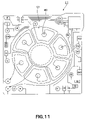
- FIG. 11 is a plan view of a first wiring board of a flat coil.
- FIG. 12 is a plan view of a second wiring board of the flat coil.
- FIG. 13 is a plan view of a third wiring board of the flat coil.
- FIG. 14 is a plan view of a fourth wiring board of the flat coil.
- FIG. 15A is a side elevation of a vibration generating weight.
- FIG. 15B is a plan view of the vibration generating weight.
- FIG. 16 is a sectional view of another embodiment of the vibration generator.
- FIGS. 17A to 17C are plan views, respectively, showing the layout of conical coil-shaped electrical connecting terminals.
- FIG. 18A is a plan view of another embodiment of the electrical connecting terminal, which is a cantilever-shaped one.
- FIG. 18B is a side elevation of the cantilever-shaped electrical connecting terminals.
- the vibration generator according to the present invention is used in a mobile phone as shown in FIGS. 1 and 2 .
- the mobile phone indicated with a reference 10 is an example of electronic devices in which the vibration generator according to the present invention is usable.
- the mobile phone 10 is for example a digital type one using a carrier frequency band of 0.8 to 1.5 GHz.
- the mobile phone 10 includes a housing 12 , antenna 14 , display 16 , operation panel 18 , microphone 20 , speaker 22 , etc.
- the operation panel 18 has a variety of operation keys as shown in FIG. 1 .
- the operation keys include a talk button 18 A, talk-off button 18 B, ten keys 18 C, etc.
- the display 16 may be formed from a liquid crystal display device, for example.
- the housing 12 includes a front portion 24 shown in FIG. 1 and a rear portion 26 shown in FIG. 2 .
- the rear portion 26 can have a battery 28 removably installed therein.
- the antenna 14 is telescopically installed to the housing 12 .
- the housing 12 shown in FIG. 1 incorporates a vibration generator 40 according to the present invention.
- the vibration generator 40 will generate a vibration upon reception of an incoming call. Namely, the vibration generator 40 can inform the user of the incoming call.
- FIG. 3 is a perspective view illustrating the outline structure of the vibration generator in detail.
- the vibration generator 40 is also called “vibration actuator”. It includes a case 43 , and a vibration motor 50 housed in the case 43 .
- FIG. 4 is an exploded perspective view of a case 43 of the vibration generator 40 .
- the vibration motor 50 is not shown in FIG. 4 .
- the case 43 includes a lid member 45 , bottom plate 47 and a thin magnetic plate 48 .
- the lid member 45 of the case 43 is formed from a magnetic-permeable material such as iron, magnetic stainless steel, silicon steel plate or the like.
- the lid member 45 closes the magnetic circuit. It should be noted that the lid member 45 may of course be omitted whenever unnecessary.
- the bottom plate 47 is a generally square plate formed from a nonmagnetic material such as aluminum, stainless steel or the like.
- the bottom plate 47 has a to-be-swaged portion 49 formed at each corner thereof.
- the bottom plate 47 has an opening 51 formed in the center thereof.
- a plurality of holes 400 is formed in the bottom plate 47 equidistantly around the opening 51 . Since the bottom plate 47 is formed from the nonmagnetic material, any force of attraction due to the magnetism of a magnet 85 of a rotor 80 will not develop between the magnet 85 and bottom plate 47 and so the rotation of the rotor 80 or the like will not be blocked by the force of attraction.
- the thin magnetic plate 48 is formed from a magnetic-permeable material such as iron, magnetic stainless steel, silicon steel plate or the like.
- the thin magnetic plate 48 is installed at the side opposite to the magnet 85 of the rotor 80 (outside the bottom plate 47 ) with the bottom plate 47 being interposed between them. So, the magnet 85 is attracted toward the bottom plate 47 under the effect of the force of attraction between the thin magnetic plate 48 and magnet 85 to prevent the rotor 80 from being lifted due to its own rotation.
- the lid member 45 shown in FIG. 4 includes a generally circular flat portion 53 and four corners 55 . Each of the corners 55 is cut (indicated at 57 ). By fitting the to-be-swaged portion 49 in a corresponding one of the cuts 57 and mechanically swaging the portion 49 , the lid member 45 and bottom plate 47 will be assembled integrally with the vibration motor 50 being placed between them as shown in FIG. 3 .
- the thin magnetic plate 48 is attached with an adhesive or the like to the bottom plate 47 . It should be noted that the thin magnetic plate 48 may be removably attached to the bottom plate 47 , which will permit to easily replace the thin magnetic plate 48 with any one having a desired size and shape whenever necessary.
- the vibration motor 50 shown in FIG. 3 is electrically connected to a main circuit board 99 via an electrical connecting terminal 270 .
- FIG. 5 is a partially fragmentary plan view with the lid member 45 in FIG. 4 being omitted to show a shape example of the vibration generator.
- FIG. 6 is a bottom view showing a shape example of the vibration generator.
- FIG. 7 is a sectional view of the vibration generator, taken along the line A—A in FIG. 6 .
- FIG. 8 is a sectional side view showing the internal structure of the vibration generator in FIG. 7 in further detail.
- the lid member 45 is formed from a material which can form a magnetic circuit, such as iron or stainless steel, for example.
- the bottom plate 47 and lid member 45 houses, in the space defined between them, the vibration motor 50 and a plurality of electronic parts 71 , 72 , 73 and 74 , for example.
- the lid member 45 is fixed to the bottom plate 47 with the vibration motor 50 being placed between them by swaging the to-be-swaged portions 49 as shown in FIGS. 3 and 4 .
- the vibration motor 50 includes a rotor 80 and stator 83 .
- the stator 83 supports the rotor 80 to be rotatable.
- the rotor 80 of the vibration motor 50 in the vibration generator 40 is put into run by supplying a current to a flat coil substrate 120 on the stator 83 from the main circuit board 99 shown in FIG. 3 , it will generate a vibration.
- the rotor 80 of the vibration motor 50 is constructed as will be described below. As shown in FIG. 7 , the rotor 80 is continuously rotatable about the central axis CL in relation to the stator 83 . As shown in FIG. 8 , the rotor 80 includes a bearing 150 , sleeve 151 , magnet 85 , vibration generating weight 87 and a rotor yoke 89 .
- the bearing 150 has a cylindrical shape. It is formed from a sintered metal or resin, for example. In case the bearing 150 is formed from a resin, for example, PPS (polyphenylene sulfide) may be employed.
- PPS polyphenylene sulfide
- the sleeve 151 is fixed to the outer surface of the bearing 150 by press fitting, for example.
- the sleeve 151 is also called “bearing housing”. It is formed from a metal such as brass, aluminum, stainless steel or the like. Also, it may be formed from a resin (PPS, for example).
- PPS resin
- the bearing 150 and sleeve 151 are separate pieces, but they may be integrally with each other, which will contribute to reduction of the number of parts used and also to reduction of the number of assembling steps.
- the energizing magnet 85 is disposed on the sleeve 151 as shown in FIG. 8 .
- the magnet 85 is a toroidal or annular one formed from a sintered material such as neodium-iron-boron compound or samarium-cobalt compound.
- the magnet 85 is fixed with an adhesive, for example, to the inner wall of the rotor yoke 89 .
- the magnet 85 shown in FIG. 8 is a multipole-magnetic type having S and N poles laid alternately along the circumference thereof.
- the rotor yoke 89 is formed from a magnetic-permeable material such as iron, stainless steel or the like. It is fixed to the outer surface of the sleeve 151 (or bearing 150 in case the sleeve 151 and bearing 150 are integral with each other) by press fitting, bonding, ultrasonic welding, swaging or by all these techniques.
- a triangular pyramid-shaped projection (not shown) provided on the end face of the sleeve 151 (or bearing 150 in case the sleeve 151 and bearing 150 are integral with each other) will permit to efficiently apply ultrasonic wave from the ultrasound emission horn through the projection and weld the rotor yoke 89 and the sleeve outer surface to each other.
- the rotor yoke 89 is generally equal in diameter to the magnet 85 .
- the weight 87 is fixed to the outer surfaces of the rotor yoke 89 and magnet 85 as shown in FIG. 8 .
- the weight 87 is semicircular in shape as shown in FIGS. 15A and 15B , and it is fixed to the rotor yoke 89 and magnet 85 by swaging or welding or with any other fixing technique as shown in FIG. 5 , for example.
- the weight 87 is an unbalancer to take out an unbalanced rotation-caused energy as a vibration component by continuously rotating the rotor 80 shown in FIG. 5 about the central axis CL of a shaft 91 in relation to the stator 83 .
- the weight 87 is formed from a material having a large specific gravity such as tungsten, for example.
- the rotor 80 shown in FIG. 8 is disposed in a space defined between the lid member 45 and bottom plate 47 .
- the magnet 85 and flat coil substrate 120 are disposed opposite to each other with a slight clearance being defined between them.
- the stator 83 is constructed as shown in FIG. 8 .
- the stator 83 includes the bottom plate 47 , thin magnetic plate 48 , flat coil substrate 120 , stationary shaft 91 , terminal housing 250 and electrical connecting terminal 270 .
- the electrical connecting terminal 270 is electrically connected to the flat coil substrate 120 by soldering, for example.
- the electrical connecting terminal 270 electrically connects the flat coil substrate 120 to an electrode 271 of the main circuit board 99 as shown in FIG. 7 .
- the electrical connecting terminal 270 is a so-called cantilever type and may be formed from an elastically deformable conductive metal such as Au or Cu.
- the terminal housing 250 shown in FIG. 8 is rectangular in shape as shown in FIG. 6 . It is a member to fix the electrical connecting terminal 270 to the bottom plate 47 .
- the terminal housing 250 is formed from an electrical insulating resin such as PPS, LCP (liquid crystal polymer) or the like.
- the terminal housing 250 covers almost the entirety of the bottom plate 47 as shown in FIG. 6 .
- the terminal housing 250 has two openings 255 formed therein, and two electrical connecting terminals 270 are exposed through the openings 255 , respectively.
- the stationary shaft 91 in FIG. 8 is welded, for example, to the lid member 45 and bottom plate 47 from which it depends.
- the central axis CL passes through the stationary shaft 91 .
- the stationary shaft 91 is fixed at one end thereof to an inner surface 45 H of the lid member 45 by welding (indicated at a reference 45 G). Also, the stationary shaft 91 is fixed at the other end thereof to an inner surface 47 H of the hole in the bottom plate 47 by welding (indicated at a reference 47 G).
- the stationary shaft 91 is formed from stainless steel, for example. It is formed rather short along the central axis CL. Both ends of the stationary shaft 91 are shaped round, not flat.
- the stationary shaft 91 can be positively fixed at one and other ends thereof to the lid member 45 and bottom plate 47 by welding (indicated at the references 45 G and 47 G). It should be noted that one or both of the ends of the stationary shaft 91 may be formed flat as necessary.
- the stationary shaft 91 is inserted in the bearing 150 of the rotor 80 and thus supported in the bearing 150 to be radially rotatable.
- the flat coil substrate 120 of the stator 83 is constructed as will be described below.
- the flat coil substrate 120 shown in FIG. 8 has a plurality of driving patterns 121 as shown in an exploded perspective view in FIG. 9 .
- the driving patterns 121 are arranged circumferentially of an opening 120 H about the central axis CL.
- FIG. 10 is a plan view showing an shape example of the driving patterns of the flat coil substrate 120 .
- the driving pattern 121 is generally fan-shaped, and six driving patterns 121 are formed circumferentially of the opening 120 H.
- the flat coil substrate 120 is fixed to the inner surface 47 M of the bottom plate 47 shown in FIG. 9 by attaching with an adhesive, for example.
- Each of the plurality of electronic parts 71 to 74 is fixed directly to the flat coil substrate 120 by attaching with an adhesive, and electrically connected to a specified point via the flat coil substrate 120 .
- the flat coil substrate 120 is formed from a stack of a plurality of thin flexible wiring boards.
- FIGS. 11 to 14 are plan views, respectively, showing wiring pattern examples of the plurality of wiring boards.
- FIG. 11 shows a first wiring board 311
- FIG. 12 shows a second wiring board 312
- FIG. 13 shows a third wiring board 313
- FIG. 14 shows a fourth wiring board 314 .
- the wiring boards 311 to 314 are stacked one on the other and electrically connected to each other to provide the driving patterns 121 .
- the driving patterns 121 formed from the stack of the first wiring board 311 to fourth wiring board 314 are advantageous as will be described below:
- the driving patterns 121 are formed from the stack of the first to fourth wiring boards 311 to 314 , for example, they can provide a rather larger magnetic field than the one provided by a single wiring board.
- the rotor 80 can be continuously rotated in relation to the stator 83 with a large driving force under the interaction between the magnetic field developed by supplying a current to the flat coil substrate 120 and magnetic field of the driving magnet 85 provided at the rotor 80 .
- the vibration generator 40 can generate a large vibration irrespectively of its smaller and thinner design.
- Each of the first to fourth wiring boards 311 to 314 shown in FIGS. 11 to 14 has a U-, V- and W-phase wires and a common wire (C).
- the flat coil substrate 120 is formed from four wiring board layers, for example, as shown in FIG. 8 .
- the flat coil substrate 120 may be formed from a single wiring board layer, or a stack of two wiring board layers, three wiring board layers or more than five wiring board layers.
- each of the driving patterns 121 is connected to the lead-out electrode of the U, V and W layers, and the lead-output electrodes are electrically connected to the main circuit board 99 shown in FIG. 3 .
- Each driving pattern 121 of the flat coil substrate 120 shown in FIG. 5 provides a three-phase full-wave energization by a sensorless system, for example, to rotate the rotor 80 in relation to the stator 83 by a three-phase full-wave driving.
- the vibration generator 40 can be designed thinner in the direction of the central axis CL and smaller in the direction of the diameter.
- the thin magnetic plate 48 attached to outside the bottom plate 47 formed from a nonmagnetic material is formed from a magnetic material as described above. So, it generates a force of attraction not developed between the bottom plate 47 and magnet 85 of the rotor 80 to prevent the rotor 80 and the like from being lifted due to their own rotation.
- the bottom plate 47 is formed from a nonmagnetic material, so no force of attraction of the magnet 85 will take place on the bottom plate 47 .
- the rotor 80 will not be attracted toward the bottom plate 47 , and the reduction of the contact friction between the bearing 150 and bottom plate 47 will provide a sufficient running torque even with the smaller, lighter rotor 80 .
- the thin magnetic plate 48 is attached to the bottom plate 47 to attract the magnet 85 toward the bottom plate 47 , to thereby prevent the rotor 80 from being lifted due to its own rotation.
- the force of attraction of the magnet 85 can be adjusted by the amount of area of the thin magnetic plate 48 , it is possible to set freely and easily a force of attraction which will prevent any rotation loss from being caused by an excessive attraction of the rotor 80 and will prevent the rotor 80 from being lifted due to its own rotation.
- the amount of area of the thin magnetic plate 48 is predetermined based on a necessary force of attraction correspondingly to the design specifications of the vibration generator 40 .
- the force of attraction of the rotor 80 can be adjusted by modifying the thin magnetic plate 48 to be installed outside, not the bottom plate 47 , so the structural strength will not be weakened.
- the electronic parts 71 to 74 shown in FIG. 5 include the following, for example. That is, the electronic part 71 is a driver IC (integrated circuit), electronic part 72 is a resistive element, and electronic parts 73 and 74 are capacitors. These electronic parts 71 to 74 are external parts but can be installed directly to the flat coil substrate 120 .
- the electronic part 71 is a driver IC (integrated circuit)
- electronic part 72 is a resistive element
- electronic parts 73 and 74 are capacitors.
- These electronic parts 71 to 74 are external parts but can be installed directly to the flat coil substrate 120 .
- the electronic parts 71 to 74 can be mounted collectively on the flat coil substrate 120 by reflowing or the like. Also, the electronic parts 71 to 74 are bare chips, for example. In this case, each of them is about 2 square millimeters in size, for example.
- the height of these electronic parts 71 to 74 in the direction of the central axis CL is such that they will not abut the weight 87 on the rotor 80 as shown in FIG. 8 .
- the weight 87 and electronic parts may be provided to overlap each other in the plane of FIG. 5 , whereby the vertical and horizontal dimensions of the vibration generator 40 can be reduced in the plane of FIG. 5 .
- the vibration generator 40 is electrically connected to the main circuit board 99 shown in FIGS. 7 and 3 via the electrical connecting terminal 270 .
- the electrical connecting terminal 270 is formed from an elastically deformable material.
- the electrical connecting terminal 270 is electrically connected to the electrode 271 of the main circuit board 99 under pressure.
- the main circuit board 99 may be formed from a relatively thick, hard substrate such as a glass fiber-reinforced epoxy resin substrate or any other type of material.
- the electrical connecting terminal 270 of the vibration generator 40 can electrically connect the driving patterns 121 of the flat coil substrate 120 and electronic parts 71 to 74 to the main circuit board 99 .
- the hole 400 is formed nearly in the center of each of the driving patterns 121 .
- the holes 400 are also shown in FIGS. 4 and 9 .
- Each of the holes 400 is formed in the central portion of each driving pattern 121 .
- the hole 400 is also formed in a corresponding position in the bottom plate 47 .
- Each hole 400 is formed in a position independent of the driving force generating portion of the driving pattern 121 .
- FIG. 16 is a sectional view of another embodiment of the vibration generator according to the present invention.
- the vibration generator 40 has a coil-shaped electrical connecting terminal 270 for electrical contact with the main circuit board.
- the electrical connecting terminal 270 in the aforementioned embodiment of the vibration generator 40 is a cantilever type formed from a conductive metal.
- the electrical connecting terminal 270 used in this embodiment is a conical coil-shaped one.
- the electrical connecting terminal 270 is formed from the elastically deformable conductive metal, its necessary area for connection to the main circuit board 99 can be smaller than that of the cantilever-shaped electrical connecting terminal 270 formed from the conductive metal and the circuit board 99 can be formed smaller with an increased freedom of designing.
- FIGS. 17A to 17C are plan views, respectively, showing the layout of conical coil-shaped electrical connecting terminal used in the vibration generator shown in FIG. 16 .
- FIG. 17A shows an example in which two electrical connecting terminals 270 are disposed to the right of the vibration generator 40 in the plane of FIG. 17A .
- FIG. 17B shows an example in which two electrical connecting terminals 270 are disposed at the diagonally opposite corners of the vibration generator 40 . Either of these layouts may be selected depending upon the layout of the wiring on the circuit board 99 to which the terminals 270 are to be connected.
- FIG. 17C shows an example in which four electrical connecting terminals 270 are disposed at all corners, respectively, of the vibration generator 40 .
- the electrical connecting terminals 270 correspond to four phases U, V, W and common, respectively, assigned to the flat coil substrate 120 .
- the present invention is not limited to this number and layout of the electrical connecting terminals 270 but the number and layout may be set correspondingly to a current to be supplied to the flat coil substrate 120 and layout of the wiring on the circuit board 99 .
- FIGS. 18A and 18B schematically illustrate other examples of the cantilever-shaped electrical connecting terminal.
- FIG. 18A is a plan view of the electrical connecting terminal
- FIG. 18B is a side elevation of the cantilever-shaped electrical connecting terminal.
- the electrical connecting terminal 270 is of a cantilever type. Namely, it is bent like L in the plan view.
- the two L-shaped electrical connecting terminals 270 are disposed along-two sides of the vibration generator 40 .
- the length from a stationary end 270 a thereof to a free end 270 b can be larger than the length of a linear electrical connecting terminal.
- the connecting terminal has a sufficient elasticity, and the horizontal displacement when the free end 270 b touches a pad of the circuit board 99 can be reduced so that the pad may be designed small.
- the free ends 270 b can be positioned at the diagonally opposite corners of the vibration generator 40 , so that two corresponding pads of the circuit board 99 can be placed with a large spacing between them and more freely without any interference between them.
- the vibration motor 50 is housed in the case 43 shown in FIG. 3 .
- the magnet 85 of the rotor 80 faces the flat coil substrate 120 of the stator 83 with a slight spacing between them.
- the vibration generator 40 including this vibration motor 50 can be designed considerably thinner in the direction of the central axis CL than the conventional motor with a brush.
- the weight 87 is formed from a material whose specific gravity is high, such as tungsten. However, a very thin, small weight 87 will be able to generate a vibration component owing to a large unbalanced rotation-caused energy when the vibration motor 50 rotates the rotor 80 .
- the lid member 45 of the case 43 shown in FIG. 3 is formed by drawing, which contributes to an improved rigidity as well as to a lighter and thinner design.
- the thin magnet 85 formed from the sintered material and thin flat coil substrate 120 like a flexible printed wiring board contributes to a smaller and thinner design of the vibration generator 40 in the direction of the central axis CL as well as to a smaller power consumption.
- the flat coil substrate 120 should preferably be formed from a stack of a plurality of wiring boards.
- Each of the plurality of wiring boards is called “laminate coil”.
- Each laminate coil is a copper-wire coil formed in polycarbonate which is an insulative material.
- the flat coil substrate 120 is fixed directly to the flat bottom plate 47 by attaching with an adhesive or the like.
- the present invention is not limited to such a fixation but the flat coil substrate 120 may be fixed to the bottom plate 47 by mechanical fixation, swaging or clipping.
- some electronic parts may electrically be connected to the electrode of the outer layer of the flat coil substrate 120 by wire bonding, for example.
- the stationary shaft 91 at the stator 83 may be fixed to the lid member 45 and bottom plate 47 by welding with YAG laser, for example.
- this fixation of the stationary shaft 91 is not limited to the welding but may of course be done by bonding, press fitting, or swaging.
- the stationary shaft 91 may be round at both ends thereof but more preferably the ends should be flat as having previously been described.
- the bearing 150 of the rotor 80 may be formed from carbon fiber-reinforced PPS, for example.
- the cylindrical bearing may be formed from a sintered metal in place of plastic.
- the bearing 150 of the rotor 80 is rotatable in relation to the stationary shaft 91 at the stator 83 . Therefore, the rotor will make no precession and shaft will not deflect when the rotor rotates as compared with the conventional supporting of the rotor shaft to be rotatable in relation to the stator bearing.
- the friction between the rotor bearing 150 and sliding portion of the stationary shaft 91 of the stator 83 will be smaller and thus the vibration generator 40 will have a longer service life.
- the bearing 150 at the rotor 80 is supported rotatably in relation to the stationary shaft 91 at the stator 83 , so it is possible to reduce the shaft deflection when the rotor 80 of the vibration generator 40 is rotated even if the vibration generator 40 has a smaller axial length.
- the vibration generator 40 can be designed thinner and smaller. It should be noted that the more approximate to the length of the stationary shaft 91 the axial length of the bearing 150 is, the smaller the shaft deflection of the rotor 80 will be.
- the vibration generator according to the present invention is applicable to the mobile phone as described above as well as to any other portable communication device such as a personal digital assistance, computer or an electronic device included in any other field.
Abstract
Description
Claims (4)
Applications Claiming Priority (5)
| Application Number | Priority Date | Filing Date | Title |
|---|---|---|---|
| JP2003-157471 | 2003-06-03 | ||
| JP2003157471 | 2003-06-03 | ||
| JP2003-286438 | 2003-08-05 | ||
| JP2003286438A JP3987011B2 (en) | 2003-06-03 | 2003-08-05 | Vibration generator and electronic device |
| PCT/JP2004/008067 WO2004108306A1 (en) | 2003-06-03 | 2004-06-03 | Vibration generator and electronic apparatus |
Publications (2)
| Publication Number | Publication Date |
|---|---|
| US20060082231A1 US20060082231A1 (en) | 2006-04-20 |
| US7161269B2 true US7161269B2 (en) | 2007-01-09 |
Family
ID=33513365
Family Applications (1)
| Application Number | Title | Priority Date | Filing Date |
|---|---|---|---|
| US10/522,337 Active US7161269B2 (en) | 2003-06-03 | 2004-06-03 | Vibration generator and electronic apparatus |
Country Status (5)
| Country | Link |
|---|---|
| US (1) | US7161269B2 (en) |
| EP (1) | EP1550514B1 (en) |
| JP (1) | JP3987011B2 (en) |
| KR (1) | KR101113804B1 (en) |
| WO (1) | WO2004108306A1 (en) |
Cited By (14)
| Publication number | Priority date | Publication date | Assignee | Title |
|---|---|---|---|---|
| US20070119968A1 (en) * | 2003-05-20 | 2007-05-31 | Optimyst Systems Inc. | Ophthalmic fluid delivery device and method of operation |
| US20090149829A1 (en) * | 2003-05-20 | 2009-06-11 | Collins Jr James F | Ophthalmic fluid delivery system |
| US20090212133A1 (en) * | 2008-01-25 | 2009-08-27 | Collins Jr James F | Ophthalmic fluid delivery device and method of operation |
| US20100007229A1 (en) * | 2008-07-08 | 2010-01-14 | Do Hyun Kim | Vibration Motor |
| US20100242640A1 (en) * | 2009-03-24 | 2010-09-30 | Motorola, Inc. | Vibrator Assembly having a Cylindrical Unbalanced Counterweight |
| US20110001384A1 (en) * | 2008-03-10 | 2011-01-06 | Nidec Copal Corporation | Motor |
| US20120169152A1 (en) * | 2011-01-05 | 2012-07-05 | Aac Acoustic Technologies (Shenzhen) Co., Ltd. | Multifunctional electromagnetic transducer |
| US8684980B2 (en) | 2010-07-15 | 2014-04-01 | Corinthian Ophthalmic, Inc. | Drop generating device |
| US8733935B2 (en) | 2010-07-15 | 2014-05-27 | Corinthian Ophthalmic, Inc. | Method and system for performing remote treatment and monitoring |
| US9087145B2 (en) | 2010-07-15 | 2015-07-21 | Eyenovia, Inc. | Ophthalmic drug delivery |
| US20170152831A1 (en) * | 2015-12-01 | 2017-06-01 | Kuo-Chang Huang | Water wave-type power generating device |
| US10154923B2 (en) | 2010-07-15 | 2018-12-18 | Eyenovia, Inc. | Drop generating device |
| US10639194B2 (en) | 2011-12-12 | 2020-05-05 | Eyenovia, Inc. | High modulus polymeric ejector mechanism, ejector device, and methods of use |
| US11938056B2 (en) | 2017-06-10 | 2024-03-26 | Eyenovia, Inc. | Methods and devices for handling a fluid and delivering the fluid to the eye |
Families Citing this family (5)
| Publication number | Priority date | Publication date | Assignee | Title |
|---|---|---|---|---|
| US7798029B2 (en) * | 2006-02-20 | 2010-09-21 | Doo Sang Kim | Vibration apparatus for generating spheroid wavelength |
| JP2017118734A (en) * | 2015-12-25 | 2017-06-29 | 日本電産セイミツ株式会社 | Vibration motor, substrate with vibration part, silent notification device, and manufacturing method of vibration motor |
| JP6664691B2 (en) | 2016-11-28 | 2020-03-13 | ミネベアミツミ株式会社 | Vibration generator and electronic equipment |
| JP6657058B2 (en) | 2016-11-28 | 2020-03-04 | ミネベアミツミ株式会社 | Electronics |
| KR102238019B1 (en) * | 2020-01-31 | 2021-05-31 | 주식회사 알머스 | Speaker unit for earphone |
Citations (7)
| Publication number | Priority date | Publication date | Assignee | Title |
|---|---|---|---|---|
| US4980590A (en) * | 1987-09-30 | 1990-12-25 | Matsushita Electric Industrial Co., Ltd. | Flat brushless motor with a back-yoke formed as an eccentric weight to induce vibrations |
| US5801466A (en) * | 1994-12-27 | 1998-09-01 | Uniden Corporation | Vibrator attaching structure |
| US5898248A (en) * | 1996-09-25 | 1999-04-27 | Matsushita Electric Industrial Co., Ltd. | Small motor holding device in individual calling receiver |
| JPH11218713A (en) | 1998-01-30 | 1999-08-10 | Fuji Xerox Co Ltd | Magnetic bearing |
| JP2001231197A (en) | 2000-02-17 | 2001-08-24 | Suzuka Fuji Xerox Co Ltd | Motor and motor for scanner |
| JP2001232290A (en) | 1999-12-15 | 2001-08-28 | Namiki Precision Jewel Co Ltd | Small and flat brushless vibration motor |
| US20040256930A1 (en) * | 2001-12-06 | 2004-12-23 | Jung-Hoon Kim | Flat noncommutator vibration motor |
Family Cites Families (3)
| Publication number | Priority date | Publication date | Assignee | Title |
|---|---|---|---|---|
| JPH0279762A (en) * | 1988-09-14 | 1990-03-20 | Sony Corp | Flat type brushless motor |
| US6051900A (en) * | 1999-08-03 | 2000-04-18 | Tokyo Parts Industrial Co., Ltd. | Flat coreless vibrator motor having no output shaft |
| JP2002291197A (en) * | 2001-03-28 | 2002-10-04 | Namiki Precision Jewel Co Ltd | Power feeder mechanism |
-
2003
- 2003-08-05 JP JP2003286438A patent/JP3987011B2/en not_active Expired - Fee Related
-
2004
- 2004-06-03 US US10/522,337 patent/US7161269B2/en active Active
- 2004-06-03 KR KR1020057001497A patent/KR101113804B1/en not_active IP Right Cessation
- 2004-06-03 EP EP04736007.8A patent/EP1550514B1/en not_active Expired - Fee Related
- 2004-06-03 WO PCT/JP2004/008067 patent/WO2004108306A1/en active Application Filing
Patent Citations (7)
| Publication number | Priority date | Publication date | Assignee | Title |
|---|---|---|---|---|
| US4980590A (en) * | 1987-09-30 | 1990-12-25 | Matsushita Electric Industrial Co., Ltd. | Flat brushless motor with a back-yoke formed as an eccentric weight to induce vibrations |
| US5801466A (en) * | 1994-12-27 | 1998-09-01 | Uniden Corporation | Vibrator attaching structure |
| US5898248A (en) * | 1996-09-25 | 1999-04-27 | Matsushita Electric Industrial Co., Ltd. | Small motor holding device in individual calling receiver |
| JPH11218713A (en) | 1998-01-30 | 1999-08-10 | Fuji Xerox Co Ltd | Magnetic bearing |
| JP2001232290A (en) | 1999-12-15 | 2001-08-28 | Namiki Precision Jewel Co Ltd | Small and flat brushless vibration motor |
| JP2001231197A (en) | 2000-02-17 | 2001-08-24 | Suzuka Fuji Xerox Co Ltd | Motor and motor for scanner |
| US20040256930A1 (en) * | 2001-12-06 | 2004-12-23 | Jung-Hoon Kim | Flat noncommutator vibration motor |
Cited By (28)
| Publication number | Priority date | Publication date | Assignee | Title |
|---|---|---|---|---|
| US20070119968A1 (en) * | 2003-05-20 | 2007-05-31 | Optimyst Systems Inc. | Ophthalmic fluid delivery device and method of operation |
| US20070119969A1 (en) * | 2003-05-20 | 2007-05-31 | Optimyst Systems Inc. | Ophthalmic fluid reservoir assembly for use with an ophthalmic fluid delivery device |
| US20090149829A1 (en) * | 2003-05-20 | 2009-06-11 | Collins Jr James F | Ophthalmic fluid delivery system |
| US7883031B2 (en) | 2003-05-20 | 2011-02-08 | James F. Collins, Jr. | Ophthalmic drug delivery system |
| US8012136B2 (en) | 2003-05-20 | 2011-09-06 | Optimyst Systems, Inc. | Ophthalmic fluid delivery device and method of operation |
| US8936021B2 (en) | 2003-05-20 | 2015-01-20 | Optimyst Systems, Inc. | Ophthalmic fluid delivery system |
| US8545463B2 (en) | 2003-05-20 | 2013-10-01 | Optimyst Systems Inc. | Ophthalmic fluid reservoir assembly for use with an ophthalmic fluid delivery device |
| US20090212133A1 (en) * | 2008-01-25 | 2009-08-27 | Collins Jr James F | Ophthalmic fluid delivery device and method of operation |
| US20110001384A1 (en) * | 2008-03-10 | 2011-01-06 | Nidec Copal Corporation | Motor |
| US8525384B2 (en) * | 2008-03-10 | 2013-09-03 | Nidec Copal Corporation | Motor |
| US20100007229A1 (en) * | 2008-07-08 | 2010-01-14 | Do Hyun Kim | Vibration Motor |
| US20100242640A1 (en) * | 2009-03-24 | 2010-09-30 | Motorola, Inc. | Vibrator Assembly having a Cylindrical Unbalanced Counterweight |
| US8733935B2 (en) | 2010-07-15 | 2014-05-27 | Corinthian Ophthalmic, Inc. | Method and system for performing remote treatment and monitoring |
| US10154923B2 (en) | 2010-07-15 | 2018-12-18 | Eyenovia, Inc. | Drop generating device |
| US11839487B2 (en) | 2010-07-15 | 2023-12-12 | Eyenovia, Inc. | Ophthalmic drug delivery |
| US11398306B2 (en) | 2010-07-15 | 2022-07-26 | Eyenovia, Inc. | Ophthalmic drug delivery |
| US9087145B2 (en) | 2010-07-15 | 2015-07-21 | Eyenovia, Inc. | Ophthalmic drug delivery |
| US11011270B2 (en) | 2010-07-15 | 2021-05-18 | Eyenovia, Inc. | Drop generating device |
| US10073949B2 (en) | 2010-07-15 | 2018-09-11 | Eyenovia, Inc. | Ophthalmic drug delivery |
| US8684980B2 (en) | 2010-07-15 | 2014-04-01 | Corinthian Ophthalmic, Inc. | Drop generating device |
| US10839960B2 (en) | 2010-07-15 | 2020-11-17 | Eyenovia, Inc. | Ophthalmic drug delivery |
| US20120169152A1 (en) * | 2011-01-05 | 2012-07-05 | Aac Acoustic Technologies (Shenzhen) Co., Ltd. | Multifunctional electromagnetic transducer |
| US8643236B2 (en) * | 2011-01-05 | 2014-02-04 | Aac Acoustic Technologies (Shenzhen) Co., Ltd. | Multifunctional electromagnetic transducer |
| US10639194B2 (en) | 2011-12-12 | 2020-05-05 | Eyenovia, Inc. | High modulus polymeric ejector mechanism, ejector device, and methods of use |
| US10646373B2 (en) | 2011-12-12 | 2020-05-12 | Eyenovia, Inc. | Ejector mechanism, ejector device, and methods of use |
| US10253748B2 (en) * | 2015-12-01 | 2019-04-09 | Kuo-Chang Huang | Water wave-type power generating device |
| US20170152831A1 (en) * | 2015-12-01 | 2017-06-01 | Kuo-Chang Huang | Water wave-type power generating device |
| US11938056B2 (en) | 2017-06-10 | 2024-03-26 | Eyenovia, Inc. | Methods and devices for handling a fluid and delivering the fluid to the eye |
Also Published As
| Publication number | Publication date |
|---|---|
| WO2004108306A1 (en) | 2004-12-16 |
| EP1550514A1 (en) | 2005-07-06 |
| EP1550514B1 (en) | 2018-11-07 |
| KR20060015442A (en) | 2006-02-17 |
| JP2005020980A (en) | 2005-01-20 |
| US20060082231A1 (en) | 2006-04-20 |
| KR101113804B1 (en) | 2012-07-27 |
| EP1550514A4 (en) | 2016-12-07 |
| JP3987011B2 (en) | 2007-10-03 |
Similar Documents
| Publication | Publication Date | Title |
|---|---|---|
| US7161269B2 (en) | Vibration generator and electronic apparatus | |
| KR100401097B1 (en) | Flat type vibration motor | |
| US7224090B2 (en) | Surface-mountable linear vibrator | |
| US8227946B2 (en) | Flat type vibration motor | |
| US7781927B2 (en) | Vibration motor | |
| JP2005192391A (en) | Method for manufacturing sector-shaped vibrating motor | |
| US8076808B2 (en) | Flat type vibration motor | |
| US6841905B2 (en) | Low-profile, coreless motor | |
| JP2005028331A (en) | Vibration generator and electronic appliance | |
| JP3894493B2 (en) | Eccentric rotor and axial gap type vibration motor provided with the eccentric rotor | |
| JP4005901B2 (en) | Vibration generator and electronic device | |
| JP2007053891A (en) | Integrated brush and vibrating motor therewith | |
| JP4022437B2 (en) | Vibration generator and electronic device | |
| TW200301037A (en) | Brushless motor | |
| JP2005012935A (en) | Molded eccentric rotor, and axial air-gap type coreless vibrating motor equipped with that rotor | |
| KR20040024442A (en) | Slim type coreless motor | |
| JP2004147386A (en) | Vibration generator and electronic apparatus | |
| JP3759092B2 (en) | Flat coreless vibration motor equipped with an eccentric rotor and the same rotor | |
| EP2009772A2 (en) | Vibration motor | |
| KR20010047771A (en) | A rotor assembly of flat type vibration motor | |
| KR20030040705A (en) | Coin-type coreless vibration motor | |
| KR20010047772A (en) | A rotor assembly of flat type vibration motor | |
| JP3605072B2 (en) | Brushless motor | |
| JP2004135463A (en) | Vibration generator and electronic equipment provided therewith | |
| JP2004289967A (en) | Vibrating motor |
Legal Events
| Date | Code | Title | Description |
|---|---|---|---|
| AS | Assignment |
Owner name: SONY CORPORATION, JAPAN Free format text: ASSIGNMENT OF ASSIGNORS INTEREST;ASSIGNORS:KAYAMA, SHUN;SHIMZU, YUKIKO;SUZUKI, MASAHIRO;AND OTHERS;REEL/FRAME:016780/0363;SIGNING DATES FROM 20050108 TO 20050215 |
|
| AS | Assignment |
Owner name: SONY CORPORATION, JAPAN Free format text: CORRECTIVE ASSIGNMENT TO CORRECT THE 2ND ASSIGNOR'S NAME AND TO ADD 2ND ASSIGNEE. DOCUMENT PREVIOUSLY RECORDED ON REEL 016780 FRAME 0363;ASSIGNORS:KAYAMA, SHUN;SHIMIZU, YUKIKO;SUZUKI, MASAHIRO;AND OTHERS;REEL/FRAME:017390/0597;SIGNING DATES FROM 20050108 TO 20050215 Owner name: OMRON CORPORATION, JAPAN Free format text: CORRECTIVE ASSIGNMENT TO CORRECT THE 2ND ASSIGNOR'S NAME AND TO ADD 2ND ASSIGNEE. DOCUMENT PREVIOUSLY RECORDED ON REEL 016780 FRAME 0363;ASSIGNORS:KAYAMA, SHUN;SHIMIZU, YUKIKO;SUZUKI, MASAHIRO;AND OTHERS;REEL/FRAME:017390/0597;SIGNING DATES FROM 20050108 TO 20050215 |
|
| STCF | Information on status: patent grant |
Free format text: PATENTED CASE |
|
| FEPP | Fee payment procedure |
Free format text: PAYER NUMBER DE-ASSIGNED (ORIGINAL EVENT CODE: RMPN); ENTITY STATUS OF PATENT OWNER: LARGE ENTITY Free format text: PAYOR NUMBER ASSIGNED (ORIGINAL EVENT CODE: ASPN); ENTITY STATUS OF PATENT OWNER: LARGE ENTITY |
|
| FEPP | Fee payment procedure |
Free format text: PAYOR NUMBER ASSIGNED (ORIGINAL EVENT CODE: ASPN); ENTITY STATUS OF PATENT OWNER: LARGE ENTITY Free format text: PAYER NUMBER DE-ASSIGNED (ORIGINAL EVENT CODE: RMPN); ENTITY STATUS OF PATENT OWNER: LARGE ENTITY |
|
| FPAY | Fee payment |
Year of fee payment: 4 |
|
| AS | Assignment |
Owner name: SONY CORPORATION, JAPAN Free format text: ASSIGNMENT OF ASSIGNORS INTEREST;ASSIGNOR:OMRON CORPORATION;REEL/FRAME:028358/0635 Effective date: 20120528 |
|
| FPAY | Fee payment |
Year of fee payment: 8 |
|
| MAFP | Maintenance fee payment |
Free format text: PAYMENT OF MAINTENANCE FEE, 12TH YEAR, LARGE ENTITY (ORIGINAL EVENT CODE: M1553) Year of fee payment: 12 |