US7158643B2 - Auto-calibrating surround system - Google Patents
Auto-calibrating surround system Download PDFInfo
- Publication number
- US7158643B2 US7158643B2 US09/839,485 US83948501A US7158643B2 US 7158643 B2 US7158643 B2 US 7158643B2 US 83948501 A US83948501 A US 83948501A US 7158643 B2 US7158643 B2 US 7158643B2
- Authority
- US
- United States
- Prior art keywords
- signal
- response
- filter
- mls
- audio
- Prior art date
- Legal status (The legal status is an assumption and is not a legal conclusion. Google has not performed a legal analysis and makes no representation as to the accuracy of the status listed.)
- Expired - Fee Related, expires
Links
- 230000004044 response Effects 0.000 claims abstract description 150
- 238000000034 method Methods 0.000 claims abstract description 44
- 238000012360 testing method Methods 0.000 claims abstract description 23
- 230000005236 sound signal Effects 0.000 claims abstract description 19
- 230000002123 temporal effect Effects 0.000 claims abstract description 8
- 230000002596 correlated effect Effects 0.000 claims abstract description 6
- 230000008569 process Effects 0.000 claims description 25
- 230000000875 corresponding effect Effects 0.000 claims description 12
- 230000002087 whitening effect Effects 0.000 claims description 6
- 230000001373 regressive effect Effects 0.000 claims description 4
- 238000012545 processing Methods 0.000 claims description 3
- 230000006870 function Effects 0.000 description 7
- 238000005259 measurement Methods 0.000 description 6
- 230000003595 spectral effect Effects 0.000 description 5
- 238000001228 spectrum Methods 0.000 description 5
- 238000012937 correction Methods 0.000 description 4
- 238000010586 diagram Methods 0.000 description 4
- 230000000694 effects Effects 0.000 description 3
- 238000005070 sampling Methods 0.000 description 3
- 230000008901 benefit Effects 0.000 description 2
- 238000005314 correlation function Methods 0.000 description 2
- 239000011159 matrix material Substances 0.000 description 2
- 230000002093 peripheral effect Effects 0.000 description 2
- 238000004088 simulation Methods 0.000 description 2
- 238000012546 transfer Methods 0.000 description 2
- 230000002745 absorbent Effects 0.000 description 1
- 239000002250 absorbent Substances 0.000 description 1
- 230000003044 adaptive effect Effects 0.000 description 1
- 238000005311 autocorrelation function Methods 0.000 description 1
- 230000008859 change Effects 0.000 description 1
- 238000006243 chemical reaction Methods 0.000 description 1
- 230000001934 delay Effects 0.000 description 1
- 238000002592 echocardiography Methods 0.000 description 1
- 238000005516 engineering process Methods 0.000 description 1
- 238000011156 evaluation Methods 0.000 description 1
- 230000007717 exclusion Effects 0.000 description 1
- 238000002474 experimental method Methods 0.000 description 1
- 238000001914 filtration Methods 0.000 description 1
- 230000000977 initiatory effect Effects 0.000 description 1
- 238000012986 modification Methods 0.000 description 1
- 230000004048 modification Effects 0.000 description 1
- 230000008450 motivation Effects 0.000 description 1
- 238000005457 optimization Methods 0.000 description 1
- 230000000737 periodic effect Effects 0.000 description 1
- 230000003252 repetitive effect Effects 0.000 description 1
- 230000035945 sensitivity Effects 0.000 description 1
- 238000000926 separation method Methods 0.000 description 1
- 230000009466 transformation Effects 0.000 description 1
- 238000011179 visual inspection Methods 0.000 description 1
Images


Classifications
-
- H—ELECTRICITY
- H04—ELECTRIC COMMUNICATION TECHNIQUE
- H04S—STEREOPHONIC SYSTEMS
- H04S7/00—Indicating arrangements; Control arrangements, e.g. balance control
- H04S7/30—Control circuits for electronic adaptation of the sound field
- H04S7/301—Automatic calibration of stereophonic sound system, e.g. with test microphone
-
- H—ELECTRICITY
- H04—ELECTRIC COMMUNICATION TECHNIQUE
- H04S—STEREOPHONIC SYSTEMS
- H04S3/00—Systems employing more than two channels, e.g. quadraphonic
-
- H—ELECTRICITY
- H04—ELECTRIC COMMUNICATION TECHNIQUE
- H04S—STEREOPHONIC SYSTEMS
- H04S7/00—Indicating arrangements; Control arrangements, e.g. balance control
- H04S7/30—Control circuits for electronic adaptation of the sound field
- H04S7/307—Frequency adjustment, e.g. tone control
Definitions
- the invention is directed to a multi-channel surround sound system, and more particularly to a surround sound system allowing automatic calibration and adjustment of the frequency, amplitude and time response of each channel.
- “Surround sound” is a term used in audio engineering to refer to sound reproduction systems that use multiple channels and speakers to provide a listener positioned between the speakers with a simulated placement of sound sources. Sound can be reproduced with a different delay and at different intensities through one or more of the speakers to “surround” the listener with sound sources and thereby create a more interesting or realistic listening experience.
- Multi-channel surround sound is employed in movie theater and home theater applications.
- the listener in a home theater is surrounded by five speakers instead of the two speakers used in traditional home stereo system. Of the five speakers, three are placed in the front of the room, with the remaining two surround speakers located to the rear or sides (THX dipolar) of the listening/viewing position.
- Dolby® SurroundTM is the original surround format, developed in the early 1970's for movie theaters.
- Dolby® DigitalTM made its debut in 1996 and is installed in more than 30,000 movie theaters and 31 million home-theater products.
- Dolby Digital is a digital format with six discrete audio channels and overcomes certain limitations of Dolby Surround which relies on a matrix system that combines four audio channels into two channels to be stored on the recording media.
- Dolby Digital is also called a 5.1 -channel format and was universally adopted several years ago for film-sound recording. Yet another new format is called Digital Theater System (DTS). DTS offers higher audio quality than Dolby Digital (1,411,200 versus 384,000 bits per second) as well as an optional 7.1 configuration.
- DTS Digital Theater System
- the audio/video preamplifier (or A/V controller) handles the job of decoding the two-channel Dolby Surround, Dolby Digital, or DTS encoded signal into the respective separate channels.
- the A/V preamplifier output provides six line level signals for the left, center, right, left surround, right surround, and subwoofer channels, respectively. These separate outputs are fed to a multiple-channel power amplifier or as is the case with an integrated receiver, are internally amplified, to drive the home-theater loudspeaker system.
- the preamplifier or receiver for the loudspeaker setup have to be configured.
- the A/V receiver or preamplifier must know the loudspeaker type, so that the bass can be directed appropriately.
- receivers may classify loudspeakers as “large” or “small”. Selecting a “small” loudspeaker will keep low-bass signals out of the speaker. This configuration is used when a subwoofer is used to reproduce low bass instead of the left and right speakers. If the system has no subwoofer and full-range left and right speakers, a “large” speaker setting should be selected.
- the setup may also require selecting “small” or “large” surround speakers.
- a center channel speaker mode (“normal” or “wide”) needs to be selected, as well as an appropriate center-channel delay so that the sound from all three front speakers arrives at a listener's ear at the same time.
- An additional short delay for the signal to the surround speakers of typically 20 ms may also have to be set to improve the apparent separation between front and rear sound.
- the loudness of each of the audio channels should be individually set to provide an overall balance in the volume from the loudspeakers.
- This process begins by producing a “test signal” in the form of noise sequentially from each speaker and adjusting the volume of each speaker independently at the listening/viewing position.
- the recommended tool for this task is the Sound Pressure Level (SPL) meter. This provides compensation for different loudspeaker sensitivities, listening-room acoustics, and loudspeaker placements. Other factors, such as an asymmetric listening space and/or angled viewing area, windows, archways and sloped ceilings, can make calibration much more complicated
- the invention is directed to a surround sound system with an automatic calibration feature for adjusting audio channel responses to the characteristic of the listening environment.
- the invention is also directed to a method that provides calibration and adjustment of the frequency, amplitude and time response of each channel of the surround sound system in a manner that is unobtrusive to a listener and can be employed during the listening experience of the listener.
- an auto-calibrating surround sound (ACSS) system includes an electro-acoustic converter, such as a loudspeaker, disposed in an audio channel and adapted to emit a sound signal in response to an electric input signal.
- the ACSS system further includes a processor that generates a test signal represented by a temporal maximum length sequence (MLS) and supplies the test signal as part of the electric input signal to the electro-acoustic converter, and an acousto-electric converter, such as a microphone, that receives the sound signal in a listening environment and supplies a received electric signal to the processor.
- the processor correlates the received electric signal with the test signal in the time domain and determines from the correlated signals a whitened response of the audio channel in the listening environment.
- the processor may include an impulse modeler that produces a error fit, for example, a polynomial least-mean-square (LMS) fit, between a desired whitened response and the whitened response determined from the correlated signals, as well as a coefficient extractor which generates from the correlated signals filter coefficients of a corrective filter to produce the whitened response of the audio channel.
- the corrective filter may be located in an audio signal path between an audio signal line input and the electro-acoustic converter and cascaded with the audio signal line input.
- the correlator and/or the IM and/or the corrective filter may be part of the processor.
- the processor can be a digital signal processor (DSP), and the ACSS system can further include A/D and D/A converters to enable digital processing of analog signals in the DSP.
- DSP digital signal processor
- a digital filter for whitening an audio channel in a listening environment includes an input receiving a digital audio signal, and a corrective filter having filter coefficients that are determined in the listening environment using a maximum length sequence (MLS) test signal.
- the corrective filter convolves the filter coefficients with the digital audio signal to form a corrected audio signal.
- An output supplies the corrected audio signal to a sound generator.
- MLS maximum length sequence
- a method of auto-calibrating a surround sound system includes the acts of producing an electric calibration signal which is a maximum length sequence (MLS) signal; supplying the calibration signal to an electro-acoustic converter which converts the calibration signal to an acoustic response; and transmitting the acoustic response as a sound wave in a listening environment to an acousto-electric converter.
- the acousto-electric converter converts the acoustic response into an electric response signal.
- the method further includes correlating the electric response signal with the electric calibration signal to compute filter coefficients, and cascading the filter coefficients with a predetermined channel response of the electro-acoustic converter to produce a whitened system response.
- method of producing a matched filter for whitening an audio channel in a listening environment includes producing in the audio channel a test output sound corresponding to a temporal maximum length sequence (MLS) signal; receiving the test output sound at a predetermined location in the listening environment, thereby producing an impulse response; analyzing a correlation between the impulse response and the MLS signal; and generating from the analyzed correlation filter coefficients of the matched filter.
- MLS temporal maximum length sequence
- Embodiments of the invention may include one or more of the following features.
- the calibration signal has a noise characteristic that is non-offensive to a listener located in the listening environment and a duration of less than approximately 3 seconds.
- the surround sound system may include a plurality of audio channels, with each channel having at least one electro-acoustic converter, wherein the whitened response is produced independently for each audio channel.
- the filter coefficients may be generated by optimizing a “closeness of fit”, for example, a least sum of squares error value, between the polynomial model and the matched filter. Optimization of the “closeness of fit” may include adjusting the length of the MLS signal.
- the matched filter can be cascaded with a useful audio signal.
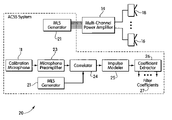
- FIG. 1 shows a schematic block diagram of an ACSS System
- FIG. 2 shows schematically a calibration process for the ACSS
- FIG. 3 shows the ACSS system in its operational phase
- FIGS. 4 a–b show an uncorrected (a) and a whitened (b) frequency response of an exemplary ACSS System
- FIG. 5 shows an exemplary minimum length sequence (MLS).
- FIG. 6 shows a digital implementation of a matched moving average (FIR) filter
- FIG. 7 schematically depicts the process of whitening a channel
- FIGS. 8 a–b show a simulated channel impulse response (a) and frequency response (b);
- FIG. 11 shows a schematic block diagram of interconnected devices of the ACSS system
- FIGS. 12 a–b show a satellite loudspeaker impulse response (a) and an overlay of corresponding frequency responses in an open environment (b);
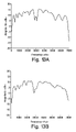
- FIG. 13 shows the frequency response of four satellite loudspeakers (a)–(d) in a listening environment
- the invention is directed to an auto-calibrating surround sound system that automatically adjusts the frequency response, amplitude response and time response of each audio channel without intervention from the listener.
- the system and method described herein can be used to whiten the frequency response of the sound system even in changing listening environments.
- a signal is defined as “white” if the signal exhibits equal energy per Hz bandwidth.
- a white or whitened response of an audio system is defined as a sound output signal produced by an electro-acoustic converter, such as a loudspeaker, that exhibits equal output energy per Hz bandwidth for an electric input signal to the system with equal electric energy per Hz bandwidth.
- an auto-calibrating surround sound (ACSS) system 10 includes a surround sound preamplifier 12 receiving audio input signal from various conventional audio devices (not shown), such as tuners, CD and DVD players, and other digital or analog signal sources, a multi-channel power amplifier 14 inserted in the signal path between the preamplifier 12 and a plurality of loudspeakers 15 , 16 , 17 , 18 , 19 located in the listening environment.
- the location of the loudspeakers is selected so that a listener has the impression of being surrounded by sound by, for example, placing loudspeakers 15 and 19 to the left and right behind the listener and loudspeakers 16 and 18 to the left and right in front of the listener.
- Loudspeaker 17 is typically located at the center to covey, for example, dialog from actors shown on a TV screen.
- the components 12 , 14 and the loudspeakers 15 , . . . , 19 are part of a conventional surround sound system.
- an auto-calibrating surround sound processor 13 is typically connected between the line level outputs of the preamplifier 12 and the line level inputs of the multi-channel power amplifier 14 .
- the auto-calibrating surround sound processor 13 has an additional input for a calibration microphone 11 as well as a user control (or menu item) for initiating a calibration sequence (not shown). Once the system 10 is calibrated, the calibration microphone 11 is no longer needed and may be disconnected until the user decides to recalibrate the system.
- the calibration phase ( FIG. 2 ) and the operational phase ( FIG. 3 ).
- the ACSS system 20 generates a calibration signal which can be a separate signal for each loudspeaker 15 , . . . , in the system (the actual number of loudspeakers being determined by the desired number of channels).
- the center loudspeaker 17 need not be calibrated.
- the calibration signal is a non-offensive noise, similar to white noise, which is only audible for a small amount of time (a total duration of 2–3 seconds or less).
- the calibration microphone 11 placed at the listener location collects the response from the loudspeakers 15 , . . . , 19 .
- the calibration noise signal in the described embodiment is pseudo-random in nature and derived from a maximal length sequence (MLS) generated by MLS generator 21 .
- the signal generated by MLS generator 21 is supplied to the power amplifier 14 to drive the loudspeakers 15 , . . . , 19 .
- the MLS is deterministic so that the samples received from the microphone 11 and optionally amplified in microphone preamplifier 23 can be correlated in correlator 24 with an exact replica of the MLS signal used to drive the loudspeakers, as indicated by a connection between correlator 24 and MLS generator 21 .
- the output of correlator 24 is supplied to impulse modeler 25 to derive the impulse response for a channel in the surround sound system 10 .
- the time of flight between the listener and each loudspeaker and the frequency response of the channel is determined.
- the power spectrum of the received signal is a function of the frequency response of the power amplifier, the loudspeakers, room acoustics, and the calibration microphone. In most cases, the dominant factors in determining the frequency response is the frequency response of the loudspeakers and the room acoustics. If any of these elements are changed or repositioned, then the power spectrum and times of flight may change.
- the measured impulse response derived from the correlator 24 is typically not well-behaved in a mathematical sense because it is not a continuous function and therefore may contain discontinuities. Some of the difficulties associated with these discontinuities can be eliminated by forming a model of the measured impulse response. This is done in the impulse modeler 25 , which creates a recursive estimator of the impulse response, using, for example, an auto-regressive (AR) curve fitting technique with a polynomial model to create a least-mean-square (LMS) error curve fit to the measured impulse response. This model of the impulse response is then used by coefficient extractor 26 to generate the coefficients 27 for a matched filter to correct the channel response.
- AR auto-regressive
- LMS least-mean-square
- FIG. 3 illustrates the operational phase of the ACSS system 30 .
- a real-time corrective filter 32 is initialized with the proper correction coefficients in the time domain for each channel in the surround sound system.
- each set of coefficients defines a filter that is unique to the requirements of the respective channel.
- the corrective filter 32 is placed in the audio signal path between the surround sound preamplifier 12 and the multi-channel power amplifier 14 to whiten the system response, as will be described in detail below.
- the corrective filter 32 can be part of the ACSS processor 13 of FIG. 1 . It is also possible to switch the corrective filter 32 in and out of the signal path as needed.
- the audio signal could be either an analog, a digital signal or some combination of analog and/or digital signals.
- FIG. 4 shows the result obtained by applying the ACSS process to an exemplary low-cost surround sound system of a type designed for personal computer systems.
- the top graph (a) shows the uncorrected amplitude response of the system in the frequency domain.
- the frequency range is limited to an upper frequency of approximately 6.5 kHz due to the limited sampling rate of the A/D converter used to sample the original impulse response.
- the lower limit of the frequency range starts at 100 Hz since the speaker is used as a satellite speaker and hence performs poorly in reproducing low frequencies.
- this particular loudspeaker has wide amplitude excursions in excess of 20 dB over the entire illustrated frequency range. Further, speaker has a noticeable 15 dB null at approximately 2.5 kHz.
- the bottom curve (b) shows the frequency response of the system after ACSS correction. The majority of the previously uncorrected amplitude excursions are now well controlled to within approximately ⁇ 2 dB of the nominal response. Moreover, the effect of the deep null in the original response, although still noticeable, is significantly reduced.
- a frequency response of a system (the changes in magnitude and delay that the system imparts to sine waves of different frequencies applied to its input) has a one-to-one relationship to an impulse response (the waveform with which a system responds to a sharp impulse applied to its input).
- the two responses can be converted into each other by a Fourier Transform and inverse Fourier Transform, respectively.
- a system such as a loudspeaker
- transformation from one to the other is a simple matter of processing the Fourier transforms (typically using a computer).
- a narrow pulse is attractive as a measurement stimulus for several reasons. It is easy to generate using inexpensive circuitry. Both the phase and magnitude of the frequency spectrum of a narrow pulse are essentially uniform over a wide range of frequencies, allowing simultaneous measurements over most or all of the amplitude and frequency ranges of a speaker and/or amplifier. Echoes in a system pulse response are easily identified and removed, so that measurements equivalent to those from an anechoic chamber can be obtained.
- a number of measures can be taken to increase the average power of the test signal. For example, repetitive pulse stimuli can be applied; however, to increase the noise rejection by 30 dB, over one thousand responses may be required, resulting in an unacceptably long calibration time.
- repetitive pulse stimuli can be applied; however, to increase the noise rejection by 30 dB, over one thousand responses may be required, resulting in an unacceptably long calibration time.
- a frequency sweep or “chirp”, or so-called “pink” noise which has an even distribution of power if the frequency is mapped in a logarithmic scale, can be employed.
- a full response measurement also takes a rather long time, as each frequency is essentially measured separately.
- pseudo-random noise is the frequency-domain version of a digital signal in the time domain known as a Pseudo-random Number (PN) pattern or Maximum Length Sequence (MLS).
- PN Pseudo-random Number
- MLS Maximum Length Sequence
- the MLS additionally has the property that its autocorrelation function represents an impulse signal, whereas the cross-correlation function between the response of a system to an MLS with the MLS itself is the impulse response of the system which can be transformed to provide the frequency response of the system, or analyzed in the time domain.
- FIG. 5 illustrates an exemplary MLS of length 7 , modified so that a digital “0” is represented as “ ⁇ 1”. If a copy of the sequence is lined up exactly underneath the original sequence (autocorrelation), as indicated in the upper portion of FIG. 5 , and the corresponding values are multiplied and all the products are summed, a value 7 equal to the length of the MLS is obtained. If the second sequence is shifted from the original sequence by, for example, 5 time intervals or clock cycles, as indicated in the lower portion of FIG. 5 , which is equivalent to a time shift of an MLS signal, then the sum of the products in this example yields a value of ⁇ 1.
- the correlation function between an N-point MLS has a sharp peak when the MLS line up exactly, with the signal being negligibly small if an MLS response signal is misregistered with respect to the original MLS signal.
- the ACSS generates a calibration signal separately for each loudspeaker in the system.
- the MLS was described above as a sequence of ⁇ -shaped (infinitely short) pulses, in practice an analog MLS may have to be generated from the digital MLS, for example, by using a zero-order-hold (ZOH) with reconstruction filter, so that the letter “S” in MLS then denotes “Signal” rather than “Sequence.”
- ZOH zero-order-hold
- the system can be modeled either in the time domain or in the frequency domain by applying a DTFT to the impulse response.
- the impulse response is modeled in the time domain.
- a response depends on a weighted average of the current and past M inputs x[i] well as a weighted average of the most recent N outputs y[k]:
- This system is sometimes also called to an Auto Regressive Moving Average (ARMA) system.
- H a (z) is the Z transform of the coefficients a n .
- the equation (3) shows that for some process Y(z) there will be some system function H(z) that will yield the white noise process V(z).
- One of the tasks in the present analysis is the determination of the transfer function H(z) for two aspects of the problem, namely to generate the process and to analyze the process.
- Creating a stable inverse filter is the main motivation for selecting the model to be of type Infinite Impulse Response (IIR).
- IIR Infinite Impulse Response
- N of the AR process in equation (2) goes to ⁇ .
- the next objective is to converge on an optimal set of finite impulse response (FIR) coefficients b n for the process analyzer that will remove the effects of the room
- a figure of merit may be defined so that the performance of the model can be analyzed. This figure of merit could be the least sum of squares error between the desired matched filter output and the output of a moving average filter. In this case, if d[n] is the desired response of the matched filter, the following error ⁇ [n] results
- Equation (7) can be seen as the linear convolution between the coefficients b n and the cross correlation of the matched filter impulse response h[n].
- the minimized error term is a function not only of the coefficients b n , but also of the filter length M.
- the filter length M can be selected by experimental means. However, as part of automating the process, it should also be possible to select the order in an adaptive fashion, without visual inspection.
- FIG. 7 is a schematic process flow diagram of an auto-calibrating process 70 that produces a whitened system response.
- the system monitors an input 71 , for example, a signal received by calibration microphone 11 . If an impulse signal is detected at 72 , an auto-regressive (AR) model is created using equations (1)–(3). A matched filter is created by process 75 using equations (5)–(6) and cascaded with the original channel, as described with reference to equations (4) and (7)–(8). If a global minimum error term is attained, step 77 , then the system response has been optimally whitened and the auto-calibration, at least for the loudspeaker under test, is terminated in 78 . Otherwise, the AR model is revised in 73 , possibly using a different model order determined by process step 74 .
- AR auto-regressive
- an exemplary simulated channel impulse has the form of an exponentially decaying sinusoidal signal that can be used to the test the deconvolution properties of an MLS.
- FIG. 8 b shows the corresponding frequency response, with the spike in the frequency response corresponding to the frequency of the dampened sinusoid.
- the AR (auto regressive) model parameters i.e., the filter taps of FIG. 6 , are generated as described above with reference to equations (7) and (8).
- the corresponding matched filter frequency response is shown in FIG.
- FIG. 9( b ) is essentially an “inverted” AR response, i.e., the filter response has poles where the AR response has zeros, and vice versa.
- a matched filter with a higher order of M, for example M 20, tends to have a sharper frequency response.
- the matched filter of FIG. 9( b ) is cascaded with the original channel to “whiten” the channel, as seen from the process flow of FIG. 7 . Filtering the original impulse response using the matched filter should produce an even distribution of spectral power.
- the hardware of the auto calibrating surround sound (ACSS) system can be implemented with standard audio components and digital signal processors.
- the evaluation board 114 is implemented as an embedded Digital Signal Processor (DSP) 116 with onboard D/A 117 and A/D 115 converters (Texas Instruments TMS320C54XDSKplus board with C 542 processor) and a 10 MHz clock.
- DSP Digital Signal Processor
- the board 114 receives suitable input signals, either in digital or analog, from input device(s) 112 .
- the other components correspond to those described above with reference to FIG. 2 .
- the first step is to initialize the processor and corresponding peripherals. Before any of the peripherals that are included either on the C 542 itself or on the DSKplus board can be used, they must be brought to the proper configuration state. For example, the input ports, the filter parameters of the board's analog interface circuit (CODEC), the analog-to-digital and digital-to-analog conversion rates are configured, and an interrupt vector table is loaded
- a system under test in this case a free space listening environment, is excited with an MLS using a loudspeaker, and a received signal is taken as the sampled output of a microphone located in the same space.
- the impulse response of the path between the two can be deconvolved by cross-correlating the stimulus MLS with the received the signal. This is done, as described above with reference to the exemplary MLS of FIG. 5 , by shifting the content of a serial port transmit register (TDXR) into the CODEC and then shifting data from the A/D converter into the serial port receive register (TRCV) and periodically convolve these data to establish the correct time scale of the received signal.
- TXR serial port transmit register
- TRCV serial port receive register
- An actual auto-calibration of an exemplary N-channel surround sound system is performed using four Klipsch Pro-Media v.2–400 speakers.
- the subwoofer and center speaker which are typically also part of a surround sound system, are not calibrated.
- Each of the speakers is calibrated separately and the corresponding coefficients are placed in a respective DSP memory.
- the matched filters can be turned on and off.
- FIGS. 12( a ) and 12 ( b ) before running the four-channel surround sound test, the impulse response for each of the satellite speakers in an open laboratory space is deconvolved using the MLS technique.
- the system is set up so that the four frequency responses can be compared. However, these measurements are not directly compared to those that are taken in the listening environment, since the microphone placement, sound pressure level at the microphone, and the surrounding acoustic impedances can all be different. Because all four responses are similar, they are plotted in an overlay fashion.
- FIG. 12( a ) shows the impulse response of an exemplary satellite speaker (in this case, the front-right speaker in the listening environment), as well as the four overlaid frequency response magnitudes.
- the time of flight delay of approximately 2.2 ms indicates that the distance between the microphone and the speaker in this test was approximately 70 cm. Verifying distances like speaker placement using the exponentially determined time of flight (TOF) is a good way to determine if the periodic cross-correlation is extracting the correct time base.
- the response feature arriving with a delay of approximately 4.3 ms indicates a first reflected signal.
- the sharp drop in frequency response at about 3 kHz will be the most difficult portion of the spectral response to whiten.
- Only a selective region of the impulse response is modeled. Selecting the region after the TOF and before the first reflection will isolate the portion of the response known as the anechoic response which the direct path between the monitor and microphone.
- a minimum phase system has most of its energy around the beginning of the impulse response; therefore a system that includes more reflections in the region of interest becomes less minimum phase and has a greater error term.
- a minimum phase system is desirable to a create a stable inverse filter.
- FIGS. 13( a )–( d ) show the responses from the four loudspeakers. It should be noted that the respective pairs front-left/rear-left loudspeakers ( FIGS. 13( a ) and 13 ( c )) and the front-right/rear-right loudspeakers ( FIGS.
- 13( b ) and 13 ( d )) have a similar response, which is due to the fact that the left satellites have a rigid wall on one side, which is essentially an infinite baffle, whereas the right satellites have no wall directly adjacent, providing a more absorbent surrounding.
- FIG. 14 the original frequency response of the front left satellite speaker was whitened using the process and system of the invention described above to illustrate that the process is capable of performing in a real listening environment.
- FIG. 14( b ) shows the LMS error curve with the marked simulated orders.
- Reflections of the sound produced by a loudspeaker may also be of interest.
- Minimizing the summed square error terms (LMS) to generate the coefficients for the matched filter also works best for minimum phase systems. However, with LMS, the error performance deteriorates if the system becomes non-minimum phase.
- Systems that employ, for example, two compensation filters could be used for whitening mixed phase systems.
- corrective filter 32 could include the ability to adjust the relative delays of the audio signals.
- DSS digital smart speakers
- Signals to these DSS loudspeakers could be analog or digital (or a combination of both analog and/or digital) and could convey audio information as well as loudspeaker identification information and electrical power.
- the user would simply connect any output of a receiver to any speaker, letting the processors decode the information which is intended for that specific location. Since transfer rates of modern networks are at least in the MHz range, technologies within the current art are fully adequate to support this level of functionality.
Abstract
Description
This system is sometimes also called to an Auto Regressive Moving Average (ARMA) system. An auto regressive (AR) process of order N can be described in terms of the inner product between a set of coefficients and the previous output values y[n]:
y[n]+a 1 ,y[n−1]+. . .+a N y[n−N]=v[n] (2)
Y(z)H a(z)=V(z) (3)
y[n]={x[n]*h 1 [n]}*h 2 [n]=x[n]*{h 1 [n]*h 2 [n]} (4)
Claims (17)
Priority Applications (1)
| Application Number | Priority Date | Filing Date | Title |
|---|---|---|---|
| US09/839,485 US7158643B2 (en) | 2000-04-21 | 2001-04-20 | Auto-calibrating surround system |
Applications Claiming Priority (2)
| Application Number | Priority Date | Filing Date | Title |
|---|---|---|---|
| US19892700P | 2000-04-21 | 2000-04-21 | |
| US09/839,485 US7158643B2 (en) | 2000-04-21 | 2001-04-20 | Auto-calibrating surround system |
Publications (2)
| Publication Number | Publication Date |
|---|---|
| US20010038702A1 US20010038702A1 (en) | 2001-11-08 |
| US7158643B2 true US7158643B2 (en) | 2007-01-02 |
Family
ID=22735476
Family Applications (1)
| Application Number | Title | Priority Date | Filing Date |
|---|---|---|---|
| US09/839,485 Expired - Fee Related US7158643B2 (en) | 2000-04-21 | 2001-04-20 | Auto-calibrating surround system |
Country Status (3)
| Country | Link |
|---|---|
| US (1) | US7158643B2 (en) |
| AU (1) | AU2001255525A1 (en) |
| WO (1) | WO2001082650A2 (en) |
Cited By (56)
| Publication number | Priority date | Publication date | Assignee | Title |
|---|---|---|---|---|
| US20030235318A1 (en) * | 2002-06-21 | 2003-12-25 | Sunil Bharitkar | System and method for automatic room acoustic correction in multi-channel audio environments |
| US20040151476A1 (en) * | 2003-02-03 | 2004-08-05 | Denon, Ltd. | Multichannel reproducing apparatus |
| US20050089182A1 (en) * | 2002-02-19 | 2005-04-28 | Troughton Paul T. | Compact surround-sound system |
| US20050207592A1 (en) * | 2002-11-21 | 2005-09-22 | Thomas Sporer | Apparatus and method of determining an impulse response and apparatus and method of presenting an audio piece |
| US20050265560A1 (en) * | 2004-04-29 | 2005-12-01 | Tim Haulick | Indoor communication system for a vehicular cabin |
| US20060056646A1 (en) * | 2004-09-07 | 2006-03-16 | Sunil Bharitkar | Phase equalization for multi-channel loudspeaker-room responses |
| US20060062404A1 (en) * | 2004-09-07 | 2006-03-23 | Sunil Bharitkar | Cross-over frequency selection and optimization of response around cross-over |
| US20060062397A1 (en) * | 2004-09-23 | 2006-03-23 | Cooper Joel C M | Technique for subwoofer distance measurement |
| US20060062399A1 (en) * | 2004-09-23 | 2006-03-23 | Mckee Cooper Joel C | Band-limited polarity detection |
| US20060062398A1 (en) * | 2004-09-23 | 2006-03-23 | Mckee Cooper Joel C | Speaker distance measurement using downsampled adaptive filter |
| US20060116779A1 (en) * | 2004-11-01 | 2006-06-01 | Samsung Electronics Co., Ltd. | Apparatus and method for tuning volume of downloaded sound |
| US20060153391A1 (en) * | 2003-01-17 | 2006-07-13 | Anthony Hooley | Set-up method for array-type sound system |
| US20060167963A1 (en) * | 2003-01-20 | 2006-07-27 | Remy Bruno | Method and device for controlling a reproduction unit using a multi-channel signal |
| US20060204022A1 (en) * | 2003-02-24 | 2006-09-14 | Anthony Hooley | Sound beam loudspeaker system |
| US20060256976A1 (en) * | 2005-05-11 | 2006-11-16 | House William N | Spatial array monitoring system |
| US20070086597A1 (en) * | 2005-10-18 | 2007-04-19 | Sony Corporation | Sound measuring apparatus and method, and audio signal processing apparatus |
| US20070086596A1 (en) * | 2005-10-19 | 2007-04-19 | Sony Corporation | Measuring apparatus, measuring method, and sound signal processing apparatus |
| US20070086553A1 (en) * | 2005-10-18 | 2007-04-19 | Sony Corporation | Frequency-characteristic-acquisition device, frequency-characteristic-acquisition method, and sound-signal-processing device |
| US20070121955A1 (en) * | 2005-11-30 | 2007-05-31 | Microsoft Corporation | Room acoustics correction device |
| US20070127736A1 (en) * | 2003-06-30 | 2007-06-07 | Markus Christoph | Handsfree system for use in a vehicle |
| US20070223763A1 (en) * | 2003-09-16 | 2007-09-27 | 1... Limited | Digital Loudspeaker |
| US20070237335A1 (en) * | 2006-04-11 | 2007-10-11 | Queen's University Of Belfast | Hormonic inversion of room impulse response signals |
| US20070269071A1 (en) * | 2004-08-10 | 2007-11-22 | 1...Limited | Non-Planar Transducer Arrays |
| US20080159571A1 (en) * | 2004-07-13 | 2008-07-03 | 1...Limited | Miniature Surround-Sound Loudspeaker |
| US20080159550A1 (en) * | 2006-12-28 | 2008-07-03 | Yoshiki Matsumoto | Signal processing device and audio playback device having the same |
| US20080292113A1 (en) * | 2007-04-13 | 2008-11-27 | Qualcomm Incorporated | Method and apparatus for audio path filter tuning |
| US20090154723A1 (en) * | 2007-12-18 | 2009-06-18 | Samsung Electronics Co., Ltd. | Method of and apparatus for controlling sound field through array speaker |
| US20090202082A1 (en) * | 2002-06-21 | 2009-08-13 | Audyssey Laboratories, Inc. | System And Method For Automatic Multiple Listener Room Acoustic Correction With Low Filter Orders |
| US20090251604A1 (en) * | 2008-04-02 | 2009-10-08 | Iyer Suraj C | Method and apparatus for selecting a signal source |
| US20090296964A1 (en) * | 2005-07-12 | 2009-12-03 | 1...Limited | Compact surround-sound effects system |
| US20090304194A1 (en) * | 2006-03-28 | 2009-12-10 | Genelec Oy | Identification Method and Apparatus in an Audio System |
| US20090323991A1 (en) * | 2008-06-23 | 2009-12-31 | Focus Enhancements, Inc. | Method of identifying speakers in a home theater system |
| US20100119075A1 (en) * | 2008-11-10 | 2010-05-13 | Rensselaer Polytechnic Institute | Spatially enveloping reverberation in sound fixing, processing, and room-acoustic simulations using coded sequences |
| US20100135119A1 (en) * | 2007-07-05 | 2010-06-03 | Christophe Paget | Method, apparatus or software for determining the location of an acoustic emission emitter in a structure |
| US20110064258A1 (en) * | 2008-04-21 | 2011-03-17 | Snaps Networks, Inc | Electrical System for a Speaker and its Control |
| US20110129101A1 (en) * | 2004-07-13 | 2011-06-02 | 1...Limited | Directional Microphone |
| WO2011123679A2 (en) * | 2010-03-31 | 2011-10-06 | Datasat Technologies Ag | Audio processing system and method |
| WO2012154823A1 (en) | 2011-05-09 | 2012-11-15 | Dts, Inc. | Room characterization and correction for multi-channel audio |
| US8325944B1 (en) | 2008-11-07 | 2012-12-04 | Adobe Systems Incorporated | Audio mixes for listening environments |
| US20140016783A1 (en) * | 2006-03-14 | 2014-01-16 | Harman International Industries, Incorporated | Extraction of Channels from Multichannel Signals Utilizing Stimulus |
| US8705764B2 (en) | 2010-10-28 | 2014-04-22 | Audyssey Laboratories, Inc. | Audio content enhancement using bandwidth extension techniques |
| US20140161281A1 (en) * | 2012-12-11 | 2014-06-12 | Amx, Llc | Audio signal correction and calibration for a room environment |
| US20140161280A1 (en) * | 2012-12-11 | 2014-06-12 | Amx, Llc | Audio signal correction and calibration for a room environment |
| US9094768B2 (en) | 2012-08-02 | 2015-07-28 | Crestron Electronics Inc. | Loudspeaker calibration using multiple wireless microphones |
| US9183838B2 (en) | 2013-10-09 | 2015-11-10 | Summit Semiconductor Llc | Digital audio transmitter and receiver |
| US9307340B2 (en) | 2010-05-06 | 2016-04-05 | Dolby Laboratories Licensing Corporation | Audio system equalization for portable media playback devices |
| US9380399B2 (en) | 2013-10-09 | 2016-06-28 | Summit Semiconductor Llc | Handheld interface for speaker location |
| US9426598B2 (en) | 2013-07-15 | 2016-08-23 | Dts, Inc. | Spatial calibration of surround sound systems including listener position estimation |
| US9462399B2 (en) | 2011-07-01 | 2016-10-04 | Dolby Laboratories Licensing Corporation | Audio playback system monitoring |
| US20160330547A1 (en) * | 2013-12-31 | 2016-11-10 | Beijing Zhigu Rui Tuo Tech Co., Ltd. | Loud-speaking, loud-speaker and interactive device |
| US20170026748A1 (en) * | 2015-07-23 | 2017-01-26 | Sony Corporation | Electronic device, method and computer program |
| US10142752B2 (en) | 2013-12-31 | 2018-11-27 | Beijing Zhigu Rui Tuo Tech Co., Ltd | Interaction with devices |
| US20190245503A1 (en) * | 2018-02-06 | 2019-08-08 | Sony Interactive Entertainment Inc | Method for dynamic sound equalization |
| US10764682B2 (en) * | 2017-05-17 | 2020-09-01 | Panasonic Intellectual Property Management Co., Ltd. | Playback system, control device, control method, and program |
| US10845479B1 (en) * | 2020-01-29 | 2020-11-24 | Synaptics Incorporated | Movement and presence detection systems and methods using sonar |
| US10861465B1 (en) * | 2019-10-10 | 2020-12-08 | Dts, Inc. | Automatic determination of speaker locations |
Families Citing this family (81)
| Publication number | Priority date | Publication date | Assignee | Title |
|---|---|---|---|---|
| EP1855506A2 (en) | 1999-09-29 | 2007-11-14 | 1...Limited | Method and apparatus to direct sound using an array of output transducers |
| KR100922910B1 (en) * | 2001-03-27 | 2009-10-22 | 캠브리지 메카트로닉스 리미티드 | Method and apparatus to create a sound field |
| CA2357200C (en) * | 2001-09-07 | 2010-05-04 | Dspfactory Ltd. | Listening device |
| GB0200149D0 (en) * | 2002-01-04 | 2002-02-20 | 1 Ltd | Surround-sound system |
| FR2836571B1 (en) * | 2002-02-28 | 2004-07-09 | Remy Henri Denis Bruno | METHOD AND DEVICE FOR DRIVING AN ACOUSTIC FIELD RESTITUTION ASSEMBLY |
| FR2844894B1 (en) * | 2002-09-23 | 2004-12-17 | Remy Henri Denis Bruno | METHOD AND SYSTEM FOR PROCESSING A REPRESENTATION OF AN ACOUSTIC FIELD |
| US20040254753A1 (en) * | 2003-04-02 | 2004-12-16 | Gn Resound A/S | Multimedia auditory test instrument |
| JP2004328513A (en) * | 2003-04-25 | 2004-11-18 | Pioneer Electronic Corp | Audio data processor, audio data processing method, its program, and recording medium with the program recorded thereon |
| GB2403386A (en) * | 2003-06-20 | 2004-12-29 | Cedar Audio Ltd | Method and apparatus for signal processing |
| DE10331757B4 (en) * | 2003-07-14 | 2005-12-08 | Micronas Gmbh | Audio playback system with a data return channel |
| JP4568536B2 (en) | 2004-03-17 | 2010-10-27 | ソニー株式会社 | Measuring device, measuring method, program |
| EP1615464A1 (en) * | 2004-07-07 | 2006-01-11 | Sony Ericsson Mobile Communications AB | Method and device for producing multichannel audio signals |
| US7697691B2 (en) | 2004-07-14 | 2010-04-13 | Intel Corporation | Method of delivering Direct Proof private keys to devices using an on-line service |
| WO2006011356A1 (en) * | 2004-07-29 | 2006-02-02 | Wakayama University | Impulse-responsive measurement method and device |
| KR100611993B1 (en) * | 2004-11-18 | 2006-08-11 | 삼성전자주식회사 | Apparatus and method for setting speaker mode automatically in multi-channel speaker system |
| JP4273344B2 (en) | 2005-04-20 | 2009-06-03 | ソニー株式会社 | Test tone signal forming method and circuit, sound field correcting method and sound field correcting apparatus |
| ATE477687T1 (en) * | 2005-06-09 | 2010-08-15 | Koninkl Philips Electronics Nv | METHOD AND SYSTEM FOR DETERMINING THE DISTANCE BETWEEN SPEAKERS |
| US7529377B2 (en) * | 2005-07-29 | 2009-05-05 | Klipsch L.L.C. | Loudspeaker with automatic calibration and room equalization |
| US20070032895A1 (en) * | 2005-07-29 | 2007-02-08 | Fawad Nackvi | Loudspeaker with demonstration mode |
| US20070030979A1 (en) * | 2005-07-29 | 2007-02-08 | Fawad Nackvi | Loudspeaker |
| US7555291B2 (en) * | 2005-08-26 | 2009-06-30 | Sony Ericsson Mobile Communications Ab | Mobile wireless communication terminals, systems, methods, and computer program products for providing a song play list |
| JP4210859B2 (en) * | 2005-10-31 | 2009-01-21 | ソニー株式会社 | Method for measuring frequency characteristics and impulse response rise time, and sound field correction apparatus |
| DE602006018703D1 (en) | 2006-04-05 | 2011-01-20 | Harman Becker Automotive Sys | Method for automatically equalizing a public address system |
| EP1843636B1 (en) * | 2006-04-05 | 2010-10-13 | Harman Becker Automotive Systems GmbH | Method for automatically equalizing a sound system |
| US8565440B2 (en) * | 2006-04-19 | 2013-10-22 | Sontia Logic Limited | Processing audio input signals |
| US20070253562A1 (en) * | 2006-04-27 | 2007-11-01 | Kite Thomas D | Method and apparatus for measuring characteristics of an audio system using a tapered chirp |
| US7558349B2 (en) * | 2006-04-27 | 2009-07-07 | Audio Precision, Inc. | Method and apparatus for measuring characteristics of a multi-channel system in the presence of crosstalk |
| US7606380B2 (en) * | 2006-04-28 | 2009-10-20 | Cirrus Logic, Inc. | Method and system for sound beam-forming using internal device speakers in conjunction with external speakers |
| US7804972B2 (en) * | 2006-05-12 | 2010-09-28 | Cirrus Logic, Inc. | Method and apparatus for calibrating a sound beam-forming system |
| US7676049B2 (en) * | 2006-05-12 | 2010-03-09 | Cirrus Logic, Inc. | Reconfigurable audio-video surround sound receiver (AVR) and method |
| US7606377B2 (en) * | 2006-05-12 | 2009-10-20 | Cirrus Logic, Inc. | Method and system for surround sound beam-forming using vertically displaced drivers |
| US7546144B2 (en) * | 2006-05-16 | 2009-06-09 | Sony Ericsson Mobile Communications Ab | Mobile wireless communication terminals, systems, methods, and computer program products for managing playback of song files |
| US7925244B2 (en) | 2006-05-30 | 2011-04-12 | Sony Ericsson Mobile Communications Ab | Mobile wireless communication terminals, systems, methods, and computer program products for publishing, sharing and accessing media files |
| US7991268B2 (en) * | 2006-08-18 | 2011-08-02 | Sony Ericsson Mobile Communications Ab | Wireless communication terminals, systems, methods, and computer program products for media file playback |
| US9319741B2 (en) * | 2006-09-07 | 2016-04-19 | Rateze Remote Mgmt Llc | Finding devices in an entertainment system |
| US8607281B2 (en) | 2006-09-07 | 2013-12-10 | Porto Vinci Ltd. Limited Liability Company | Control of data presentation in multiple zones using a wireless home entertainment hub |
| JP2008072206A (en) * | 2006-09-12 | 2008-03-27 | Onkyo Corp | Multichannel audio amplification device |
| US8279709B2 (en) * | 2007-07-18 | 2012-10-02 | Bang & Olufsen A/S | Loudspeaker position estimation |
| JP4843691B2 (en) * | 2009-03-09 | 2011-12-21 | 株式会社東芝 | Signal characteristic change device |
| JP5885918B2 (en) * | 2010-10-29 | 2016-03-16 | ソニー株式会社 | Display device, audio signal processing method and program |
| JP5604275B2 (en) * | 2010-12-02 | 2014-10-08 | 富士通テン株式会社 | Correlation reduction method, audio signal conversion apparatus, and sound reproduction apparatus |
| ES2399160B2 (en) * | 2011-04-19 | 2013-07-19 | Antonio Raúl LEAL RAMÍREZ | Methods, devices and applications for spatial calibration of an acoustic environment |
| US9060237B2 (en) * | 2011-06-29 | 2015-06-16 | Harman International Industries, Incorporated | Musical measurement stimuli |
| GB2493029B (en) * | 2011-07-22 | 2013-10-23 | Mikko Pekka Vainiala | Method and apparatus for impulse response measurement and simulation |
| US9084058B2 (en) | 2011-12-29 | 2015-07-14 | Sonos, Inc. | Sound field calibration using listener localization |
| US9106192B2 (en) * | 2012-06-28 | 2015-08-11 | Sonos, Inc. | System and method for device playback calibration |
| US9219460B2 (en) | 2014-03-17 | 2015-12-22 | Sonos, Inc. | Audio settings based on environment |
| US9690539B2 (en) | 2012-06-28 | 2017-06-27 | Sonos, Inc. | Speaker calibration user interface |
| US9706323B2 (en) | 2014-09-09 | 2017-07-11 | Sonos, Inc. | Playback device calibration |
| US9668049B2 (en) | 2012-06-28 | 2017-05-30 | Sonos, Inc. | Playback device calibration user interfaces |
| US9690271B2 (en) | 2012-06-28 | 2017-06-27 | Sonos, Inc. | Speaker calibration |
| CN105210389B (en) * | 2013-03-19 | 2017-07-25 | 皇家飞利浦有限公司 | For the method and apparatus for the position for determining microphone |
| US9264839B2 (en) | 2014-03-17 | 2016-02-16 | Sonos, Inc. | Playback device configuration based on proximity detection |
| US9910634B2 (en) | 2014-09-09 | 2018-03-06 | Sonos, Inc. | Microphone calibration |
| US9952825B2 (en) | 2014-09-09 | 2018-04-24 | Sonos, Inc. | Audio processing algorithms |
| US9891881B2 (en) | 2014-09-09 | 2018-02-13 | Sonos, Inc. | Audio processing algorithm database |
| US10127006B2 (en) | 2014-09-09 | 2018-11-13 | Sonos, Inc. | Facilitating calibration of an audio playback device |
| DE102015106114B4 (en) * | 2015-04-21 | 2017-10-26 | D & B Audiotechnik Gmbh | METHOD AND DEVICE FOR POSITION DETECTION OF SPEAKER BOXES OF A SPEAKER BOX ARRANGEMENT |
| WO2016172593A1 (en) | 2015-04-24 | 2016-10-27 | Sonos, Inc. | Playback device calibration user interfaces |
| US10664224B2 (en) | 2015-04-24 | 2020-05-26 | Sonos, Inc. | Speaker calibration user interface |
| US9538305B2 (en) | 2015-07-28 | 2017-01-03 | Sonos, Inc. | Calibration error conditions |
| US9913056B2 (en) * | 2015-08-06 | 2018-03-06 | Dolby Laboratories Licensing Corporation | System and method to enhance speakers connected to devices with microphones |
| CN108028985B (en) | 2015-09-17 | 2020-03-13 | 搜诺思公司 | Method for computing device |
| US9693165B2 (en) | 2015-09-17 | 2017-06-27 | Sonos, Inc. | Validation of audio calibration using multi-dimensional motion check |
| US10708701B2 (en) * | 2015-10-28 | 2020-07-07 | Music Tribe Global Brands Ltd. | Sound level estimation |
| US9743207B1 (en) | 2016-01-18 | 2017-08-22 | Sonos, Inc. | Calibration using multiple recording devices |
| US10003899B2 (en) | 2016-01-25 | 2018-06-19 | Sonos, Inc. | Calibration with particular locations |
| US11106423B2 (en) | 2016-01-25 | 2021-08-31 | Sonos, Inc. | Evaluating calibration of a playback device |
| US9864574B2 (en) | 2016-04-01 | 2018-01-09 | Sonos, Inc. | Playback device calibration based on representation spectral characteristics |
| US9860662B2 (en) | 2016-04-01 | 2018-01-02 | Sonos, Inc. | Updating playback device configuration information based on calibration data |
| US9763018B1 (en) | 2016-04-12 | 2017-09-12 | Sonos, Inc. | Calibration of audio playback devices |
| US9860670B1 (en) | 2016-07-15 | 2018-01-02 | Sonos, Inc. | Spectral correction using spatial calibration |
| US9794710B1 (en) | 2016-07-15 | 2017-10-17 | Sonos, Inc. | Spatial audio correction |
| US10372406B2 (en) | 2016-07-22 | 2019-08-06 | Sonos, Inc. | Calibration interface |
| US9769582B1 (en) * | 2016-08-02 | 2017-09-19 | Amazon Technologies, Inc. | Audio source and audio sensor testing |
| US10459684B2 (en) | 2016-08-05 | 2019-10-29 | Sonos, Inc. | Calibration of a playback device based on an estimated frequency response |
| US10375498B2 (en) | 2016-11-16 | 2019-08-06 | Dts, Inc. | Graphical user interface for calibrating a surround sound system |
| CN107172568B (en) * | 2017-06-29 | 2024-04-05 | 深圳市泰衡诺科技有限公司上海分公司 | Stereo sound field calibration equipment and calibration method |
| US11206484B2 (en) | 2018-08-28 | 2021-12-21 | Sonos, Inc. | Passive speaker authentication |
| US10299061B1 (en) | 2018-08-28 | 2019-05-21 | Sonos, Inc. | Playback device calibration |
| US10734965B1 (en) | 2019-08-12 | 2020-08-04 | Sonos, Inc. | Audio calibration of a portable playback device |
Citations (7)
| Publication number | Priority date | Publication date | Assignee | Title |
|---|---|---|---|---|
| US4628530A (en) * | 1983-02-23 | 1986-12-09 | U. S. Philips Corporation | Automatic equalizing system with DFT and FFT |
| US5481615A (en) * | 1993-04-01 | 1996-01-02 | Noise Cancellation Technologies, Inc. | Audio reproduction system |
| US5666424A (en) * | 1990-06-08 | 1997-09-09 | Harman International Industries, Inc. | Six-axis surround sound processor with automatic balancing and calibration |
| US5742694A (en) * | 1996-07-12 | 1998-04-21 | Eatwell; Graham P. | Noise reduction filter |
| JPH10136498A (en) | 1996-10-24 | 1998-05-22 | Fuji Film Micro Device Kk | Automatic setting system for audio device |
| US6639989B1 (en) * | 1998-09-25 | 2003-10-28 | Nokia Display Products Oy | Method for loudness calibration of a multichannel sound systems and a multichannel sound system |
| US6718041B2 (en) * | 2000-10-03 | 2004-04-06 | France Telecom | Echo attenuating method and device |
-
2001
- 2001-04-20 AU AU2001255525A patent/AU2001255525A1/en not_active Abandoned
- 2001-04-20 US US09/839,485 patent/US7158643B2/en not_active Expired - Fee Related
- 2001-04-20 WO PCT/US2001/012871 patent/WO2001082650A2/en active Application Filing
Patent Citations (8)
| Publication number | Priority date | Publication date | Assignee | Title |
|---|---|---|---|---|
| US4628530A (en) * | 1983-02-23 | 1986-12-09 | U. S. Philips Corporation | Automatic equalizing system with DFT and FFT |
| US5666424A (en) * | 1990-06-08 | 1997-09-09 | Harman International Industries, Inc. | Six-axis surround sound processor with automatic balancing and calibration |
| US5481615A (en) * | 1993-04-01 | 1996-01-02 | Noise Cancellation Technologies, Inc. | Audio reproduction system |
| WO1997040642A1 (en) | 1996-04-24 | 1997-10-30 | Harman International Industries, Inc. | Six-axis surround sound processor with automatic balancing and calibration |
| US5742694A (en) * | 1996-07-12 | 1998-04-21 | Eatwell; Graham P. | Noise reduction filter |
| JPH10136498A (en) | 1996-10-24 | 1998-05-22 | Fuji Film Micro Device Kk | Automatic setting system for audio device |
| US6639989B1 (en) * | 1998-09-25 | 2003-10-28 | Nokia Display Products Oy | Method for loudness calibration of a multichannel sound systems and a multichannel sound system |
| US6718041B2 (en) * | 2000-10-03 | 2004-04-06 | France Telecom | Echo attenuating method and device |
Cited By (106)
| Publication number | Priority date | Publication date | Assignee | Title |
|---|---|---|---|---|
| US20050089182A1 (en) * | 2002-02-19 | 2005-04-28 | Troughton Paul T. | Compact surround-sound system |
| US20030235318A1 (en) * | 2002-06-21 | 2003-12-25 | Sunil Bharitkar | System and method for automatic room acoustic correction in multi-channel audio environments |
| US8005228B2 (en) | 2002-06-21 | 2011-08-23 | Audyssey Laboratories, Inc. | System and method for automatic multiple listener room acoustic correction with low filter orders |
| US7769183B2 (en) * | 2002-06-21 | 2010-08-03 | University Of Southern California | System and method for automatic room acoustic correction in multi-channel audio environments |
| US20090202082A1 (en) * | 2002-06-21 | 2009-08-13 | Audyssey Laboratories, Inc. | System And Method For Automatic Multiple Listener Room Acoustic Correction With Low Filter Orders |
| US20050207592A1 (en) * | 2002-11-21 | 2005-09-22 | Thomas Sporer | Apparatus and method of determining an impulse response and apparatus and method of presenting an audio piece |
| US7881485B2 (en) * | 2002-11-21 | 2011-02-01 | Fraunhofer-Gesellschaft Zur Foerderung Der Angewandten Forschung E. V. | Apparatus and method of determining an impulse response and apparatus and method of presenting an audio piece |
| US8594350B2 (en) | 2003-01-17 | 2013-11-26 | Yamaha Corporation | Set-up method for array-type sound system |
| US20060153391A1 (en) * | 2003-01-17 | 2006-07-13 | Anthony Hooley | Set-up method for array-type sound system |
| US8213621B2 (en) * | 2003-01-20 | 2012-07-03 | Trinnov Audio | Method and device for controlling a reproduction unit using a multi-channel |
| US20060167963A1 (en) * | 2003-01-20 | 2006-07-27 | Remy Bruno | Method and device for controlling a reproduction unit using a multi-channel signal |
| US20040151476A1 (en) * | 2003-02-03 | 2004-08-05 | Denon, Ltd. | Multichannel reproducing apparatus |
| US20060204022A1 (en) * | 2003-02-24 | 2006-09-14 | Anthony Hooley | Sound beam loudspeaker system |
| US7826623B2 (en) * | 2003-06-30 | 2010-11-02 | Nuance Communications, Inc. | Handsfree system for use in a vehicle |
| US8009841B2 (en) | 2003-06-30 | 2011-08-30 | Nuance Communications, Inc. | Handsfree communication system |
| US20070127736A1 (en) * | 2003-06-30 | 2007-06-07 | Markus Christoph | Handsfree system for use in a vehicle |
| US20070172079A1 (en) * | 2003-06-30 | 2007-07-26 | Markus Christoph | Handsfree communication system |
| US20070223763A1 (en) * | 2003-09-16 | 2007-09-27 | 1... Limited | Digital Loudspeaker |
| US8081776B2 (en) * | 2004-04-29 | 2011-12-20 | Harman Becker Automotive Systems Gmbh | Indoor communication system for a vehicular cabin |
| US20050265560A1 (en) * | 2004-04-29 | 2005-12-01 | Tim Haulick | Indoor communication system for a vehicular cabin |
| US20110129101A1 (en) * | 2004-07-13 | 2011-06-02 | 1...Limited | Directional Microphone |
| US20080159571A1 (en) * | 2004-07-13 | 2008-07-03 | 1...Limited | Miniature Surround-Sound Loudspeaker |
| US20070269071A1 (en) * | 2004-08-10 | 2007-11-22 | 1...Limited | Non-Planar Transducer Arrays |
| US7826626B2 (en) | 2004-09-07 | 2010-11-02 | Audyssey Laboratories, Inc. | Cross-over frequency selection and optimization of response around cross-over |
| US8363852B2 (en) | 2004-09-07 | 2013-01-29 | Audyssey Laboratories, Inc. | Cross-over frequency selection and optimization of response around cross-over |
| US20060056646A1 (en) * | 2004-09-07 | 2006-03-16 | Sunil Bharitkar | Phase equalization for multi-channel loudspeaker-room responses |
| US20060062404A1 (en) * | 2004-09-07 | 2006-03-23 | Sunil Bharitkar | Cross-over frequency selection and optimization of response around cross-over |
| US20100310092A1 (en) * | 2004-09-07 | 2010-12-09 | Audyssey Laboratories, Inc. | Cross-over frequency selection and optimization of response around cross-over |
| US8218789B2 (en) | 2004-09-07 | 2012-07-10 | Audyssey Laboratories, Inc. | Phase equalization for multi-channel loudspeaker-room responses |
| US20100189282A1 (en) * | 2004-09-07 | 2010-07-29 | Audyssey Laboratories, Inc. | Phase equalization for multi-channel loudspeaker-room responses |
| US7720237B2 (en) | 2004-09-07 | 2010-05-18 | Audyssey Laboratories, Inc. | Phase equalization for multi-channel loudspeaker-room responses |
| US20060062397A1 (en) * | 2004-09-23 | 2006-03-23 | Cooper Joel C M | Technique for subwoofer distance measurement |
| US20060062398A1 (en) * | 2004-09-23 | 2006-03-23 | Mckee Cooper Joel C | Speaker distance measurement using downsampled adaptive filter |
| US20060062399A1 (en) * | 2004-09-23 | 2006-03-23 | Mckee Cooper Joel C | Band-limited polarity detection |
| US7949139B2 (en) * | 2004-09-23 | 2011-05-24 | Cirrus Logic, Inc. | Technique for subwoofer distance measurement |
| US7957823B2 (en) * | 2004-11-01 | 2011-06-07 | Samsung Electronics Co., Ltd | Apparatus and method for tuning volume of downloaded sound |
| US20060116779A1 (en) * | 2004-11-01 | 2006-06-01 | Samsung Electronics Co., Ltd. | Apparatus and method for tuning volume of downloaded sound |
| US20060256976A1 (en) * | 2005-05-11 | 2006-11-16 | House William N | Spatial array monitoring system |
| US20090296964A1 (en) * | 2005-07-12 | 2009-12-03 | 1...Limited | Compact surround-sound effects system |
| US20070086597A1 (en) * | 2005-10-18 | 2007-04-19 | Sony Corporation | Sound measuring apparatus and method, and audio signal processing apparatus |
| US20070086553A1 (en) * | 2005-10-18 | 2007-04-19 | Sony Corporation | Frequency-characteristic-acquisition device, frequency-characteristic-acquisition method, and sound-signal-processing device |
| US8130967B2 (en) * | 2005-10-18 | 2012-03-06 | Sony Corporation | Frequency-characteristic-acquisition device, frequency-characteristic-acquisition method, and sound-signal-processing device |
| US7949140B2 (en) * | 2005-10-18 | 2011-05-24 | Sony Corporation | Sound measuring apparatus and method, and audio signal processing apparatus |
| US20070086596A1 (en) * | 2005-10-19 | 2007-04-19 | Sony Corporation | Measuring apparatus, measuring method, and sound signal processing apparatus |
| US7961893B2 (en) * | 2005-10-19 | 2011-06-14 | Sony Corporation | Measuring apparatus, measuring method, and sound signal processing apparatus |
| US20070121955A1 (en) * | 2005-11-30 | 2007-05-31 | Microsoft Corporation | Room acoustics correction device |
| US20140016783A1 (en) * | 2006-03-14 | 2014-01-16 | Harman International Industries, Incorporated | Extraction of Channels from Multichannel Signals Utilizing Stimulus |
| US9241230B2 (en) * | 2006-03-14 | 2016-01-19 | Harman International Industries, Incorporated | Extraction of channels from multichannel signals utilizing stimulus |
| US20090304194A1 (en) * | 2006-03-28 | 2009-12-10 | Genelec Oy | Identification Method and Apparatus in an Audio System |
| US20070237335A1 (en) * | 2006-04-11 | 2007-10-11 | Queen's University Of Belfast | Hormonic inversion of room impulse response signals |
| US20080159550A1 (en) * | 2006-12-28 | 2008-07-03 | Yoshiki Matsumoto | Signal processing device and audio playback device having the same |
| US8249260B2 (en) * | 2007-04-13 | 2012-08-21 | Qualcomm Incorporated | Method and apparatus for audio path filter tuning |
| US20080292113A1 (en) * | 2007-04-13 | 2008-11-27 | Qualcomm Incorporated | Method and apparatus for audio path filter tuning |
| US20100135119A1 (en) * | 2007-07-05 | 2010-06-03 | Christophe Paget | Method, apparatus or software for determining the location of an acoustic emission emitter in a structure |
| US8208344B2 (en) * | 2007-07-05 | 2012-06-26 | Airbus Operations Limited | Method, apparatus or software for determining the location of an acoustic emission emitter in a structure |
| US8045722B2 (en) * | 2007-12-18 | 2011-10-25 | Samsung Electronics Co., Ltd. | Method of and apparatus for controlling sound field through array speaker |
| US20090154723A1 (en) * | 2007-12-18 | 2009-06-18 | Samsung Electronics Co., Ltd. | Method of and apparatus for controlling sound field through array speaker |
| KR101445075B1 (en) | 2007-12-18 | 2014-09-29 | 삼성전자주식회사 | Method and apparatus for controlling sound field through array speaker |
| US20090251604A1 (en) * | 2008-04-02 | 2009-10-08 | Iyer Suraj C | Method and apparatus for selecting a signal source |
| US9654718B2 (en) * | 2008-04-02 | 2017-05-16 | Bose Corporation | Method and apparatus for selecting a signal source |
| US20110064258A1 (en) * | 2008-04-21 | 2011-03-17 | Snaps Networks, Inc | Electrical System for a Speaker and its Control |
| US9872091B2 (en) | 2008-04-21 | 2018-01-16 | Caavo Inc | Electrical system for a speaker and its control |
| US8588431B2 (en) * | 2008-04-21 | 2013-11-19 | Snap Networks, Inc. | Electrical system for a speaker and its control |
| US8199941B2 (en) * | 2008-06-23 | 2012-06-12 | Summit Semiconductor Llc | Method of identifying speakers in a home theater system |
| US20090323991A1 (en) * | 2008-06-23 | 2009-12-31 | Focus Enhancements, Inc. | Method of identifying speakers in a home theater system |
| US8325944B1 (en) | 2008-11-07 | 2012-12-04 | Adobe Systems Incorporated | Audio mixes for listening environments |
| US20100119075A1 (en) * | 2008-11-10 | 2010-05-13 | Rensselaer Polytechnic Institute | Spatially enveloping reverberation in sound fixing, processing, and room-acoustic simulations using coded sequences |
| WO2011123679A2 (en) * | 2010-03-31 | 2011-10-06 | Datasat Technologies Ag | Audio processing system and method |
| WO2011123679A3 (en) * | 2010-03-31 | 2011-12-22 | Datasat Technologies Ag | Audio processing system and method |
| US9307340B2 (en) | 2010-05-06 | 2016-04-05 | Dolby Laboratories Licensing Corporation | Audio system equalization for portable media playback devices |
| US8705764B2 (en) | 2010-10-28 | 2014-04-22 | Audyssey Laboratories, Inc. | Audio content enhancement using bandwidth extension techniques |
| WO2012154823A1 (en) | 2011-05-09 | 2012-11-15 | Dts, Inc. | Room characterization and correction for multi-channel audio |
| US9031268B2 (en) | 2011-05-09 | 2015-05-12 | Dts, Inc. | Room characterization and correction for multi-channel audio |
| US9641952B2 (en) | 2011-05-09 | 2017-05-02 | Dts, Inc. | Room characterization and correction for multi-channel audio |
| US9602940B2 (en) | 2011-07-01 | 2017-03-21 | Dolby Laboratories Licensing Corporation | Audio playback system monitoring |
| US9462399B2 (en) | 2011-07-01 | 2016-10-04 | Dolby Laboratories Licensing Corporation | Audio playback system monitoring |
| US9094768B2 (en) | 2012-08-02 | 2015-07-28 | Crestron Electronics Inc. | Loudspeaker calibration using multiple wireless microphones |
| US20140161281A1 (en) * | 2012-12-11 | 2014-06-12 | Amx, Llc | Audio signal correction and calibration for a room environment |
| US9036825B2 (en) * | 2012-12-11 | 2015-05-19 | Amx Llc | Audio signal correction and calibration for a room environment |
| US10028055B2 (en) * | 2012-12-11 | 2018-07-17 | Amx, Llc | Audio signal correction and calibration for a room environment |
| US20160192104A1 (en) * | 2012-12-11 | 2016-06-30 | Amx Llc | Audio signal correction and calibration for a room environment |
| US9414164B2 (en) * | 2012-12-11 | 2016-08-09 | Amx Llc | Audio signal correction and calibration for a room environment |
| US20140161280A1 (en) * | 2012-12-11 | 2014-06-12 | Amx, Llc | Audio signal correction and calibration for a room environment |
| US9716962B2 (en) * | 2012-12-11 | 2017-07-25 | Amx Llc | Audio signal correction and calibration for a room environment |
| US9699557B2 (en) * | 2012-12-11 | 2017-07-04 | Amx Llc | Audio signal correction and calibration for a room environment |
| US20160316295A1 (en) * | 2012-12-11 | 2016-10-27 | Amx Llc | Audio signal correction and calibration for a room environment |
| US9313601B2 (en) * | 2012-12-11 | 2016-04-12 | Amx Llc | Audio signal correction and calibration for a room environment |
| US9554230B2 (en) * | 2012-12-11 | 2017-01-24 | Amx Llc | Audio signal correction and calibration for a room environment |
| US20150237445A1 (en) * | 2012-12-11 | 2015-08-20 | Amx Llc | Audio signal correction and calibration for a room environment |
| US9137619B2 (en) * | 2012-12-11 | 2015-09-15 | Amx Llc | Audio signal correction and calibration for a room environment |
| US20170099559A1 (en) * | 2012-12-11 | 2017-04-06 | Amx Llc | Audio signal correction and calibration for a room environment |
| US9426598B2 (en) | 2013-07-15 | 2016-08-23 | Dts, Inc. | Spatial calibration of surround sound systems including listener position estimation |
| US9380399B2 (en) | 2013-10-09 | 2016-06-28 | Summit Semiconductor Llc | Handheld interface for speaker location |
| US9454968B2 (en) | 2013-10-09 | 2016-09-27 | Summit Semiconductor Llc | Digital audio transmitter and receiver |
| US9183838B2 (en) | 2013-10-09 | 2015-11-10 | Summit Semiconductor Llc | Digital audio transmitter and receiver |
| US10142752B2 (en) | 2013-12-31 | 2018-11-27 | Beijing Zhigu Rui Tuo Tech Co., Ltd | Interaction with devices |
| US20160330547A1 (en) * | 2013-12-31 | 2016-11-10 | Beijing Zhigu Rui Tuo Tech Co., Ltd. | Loud-speaking, loud-speaker and interactive device |
| US10149055B2 (en) * | 2013-12-31 | 2018-12-04 | Beijing Zhigu Rui Tuo Tech Co., Ltd | Loud-speaking, loud-speaker and interactive device |
| US9936295B2 (en) * | 2015-07-23 | 2018-04-03 | Sony Corporation | Electronic device, method and computer program |
| US20170026748A1 (en) * | 2015-07-23 | 2017-01-26 | Sony Corporation | Electronic device, method and computer program |
| US10764682B2 (en) * | 2017-05-17 | 2020-09-01 | Panasonic Intellectual Property Management Co., Ltd. | Playback system, control device, control method, and program |
| US20190245503A1 (en) * | 2018-02-06 | 2019-08-08 | Sony Interactive Entertainment Inc | Method for dynamic sound equalization |
| WO2019156888A1 (en) * | 2018-02-06 | 2019-08-15 | Sony Interactive Entertainment Inc. | Method for dynamic sound equalization |
| US10523171B2 (en) * | 2018-02-06 | 2019-12-31 | Sony Interactive Entertainment Inc. | Method for dynamic sound equalization |
| US10861465B1 (en) * | 2019-10-10 | 2020-12-08 | Dts, Inc. | Automatic determination of speaker locations |
| US10845479B1 (en) * | 2020-01-29 | 2020-11-24 | Synaptics Incorporated | Movement and presence detection systems and methods using sonar |
Also Published As
| Publication number | Publication date |
|---|---|
| WO2001082650A3 (en) | 2002-08-15 |
| US20010038702A1 (en) | 2001-11-08 |
| WO2001082650A2 (en) | 2001-11-01 |
| AU2001255525A1 (en) | 2001-11-07 |
Similar Documents
| Publication | Publication Date | Title |
|---|---|---|
| US7158643B2 (en) | Auto-calibrating surround system | |
| US9641952B2 (en) | Room characterization and correction for multi-channel audio | |
| US7881485B2 (en) | Apparatus and method of determining an impulse response and apparatus and method of presenting an audio piece | |
| US4458362A (en) | Automatic time domain equalization of audio signals | |
| US6639989B1 (en) | Method for loudness calibration of a multichannel sound systems and a multichannel sound system | |
| EP3214859A1 (en) | Apparatus and method for determining delay and gain parameters for calibrating a multi channel audio system | |
| CA2335486C (en) | Apparatus and method for adjusting audio equipment in acoustic environments | |
| JP3565908B2 (en) | Simulation method and apparatus for three-dimensional effect and / or acoustic characteristic effect | |
| EP1677573B1 (en) | Equalization system to improve the quality of bass sounds within a listening area | |
| US7822496B2 (en) | Audio signal processing method and apparatus | |
| EP1545155A2 (en) | Automatic sound field correcting device and computer program therefor | |
| WO2009058192A1 (en) | Dynamic equalizer | |
| Fielder | Analysis of traditional and reverberation-reducing methods of room equalization | |
| US20060062398A1 (en) | Speaker distance measurement using downsampled adaptive filter | |
| EP0553832A1 (en) | Sound field controller | |
| US20050207582A1 (en) | Test apparatus, test method, and computer program | |
| US8031876B2 (en) | Audio system | |
| US20060062399A1 (en) | Band-limited polarity detection | |
| US20170373656A1 (en) | Loudspeaker-room equalization with perceptual correction of spectral dips | |
| EP1511358A2 (en) | Automatic sound field correction apparatus and computer program therefor | |
| EP1534047A2 (en) | Sound characteristic measuring device and method, automatic sound field correcting device and method | |
| Benjamin et al. | The effect of room acoustics on subwoofer performance and level setting | |
| Hill et al. | Enhanced wide-area low-frequency sound reproduction in cinemas: effective and practical alternatives to current calibration strategies | |
| EP3506660B1 (en) | Method for calibrating an audio reproduction system and corresponding audio reproduction system | |
| Extra et al. | Artificial reverberation: Comparing algorithms by using monaural analysis tools |
Legal Events
| Date | Code | Title | Description |
|---|---|---|---|
| AS | Assignment |
Owner name: KEYHOLD ENGINEERING, INC., MASSACHUSETTS Free format text: ASSIGNMENT OF ASSIGNORS INTEREST;ASSIGNORS:LAVOIE, BRUCE P.;MICHALSON, WILLIAM R.;REEL/FRAME:011759/0951 Effective date: 20010413 |
|
| FEPP | Fee payment procedure |
Free format text: PAT HOLDER CLAIMS SMALL ENTITY STATUS, ENTITY STATUS SET TO SMALL (ORIGINAL EVENT CODE: LTOS); ENTITY STATUS OF PATENT OWNER: SMALL ENTITY |
|
| FPAY | Fee payment |
Year of fee payment: 4 |
|
| REMI | Maintenance fee reminder mailed | ||
| FPAY | Fee payment |
Year of fee payment: 8 |
|
| SULP | Surcharge for late payment |
Year of fee payment: 7 |
|
| FEPP | Fee payment procedure |
Free format text: MAINTENANCE FEE REMINDER MAILED (ORIGINAL EVENT CODE: REM.) |
|
| LAPS | Lapse for failure to pay maintenance fees |
Free format text: PATENT EXPIRED FOR FAILURE TO PAY MAINTENANCE FEES (ORIGINAL EVENT CODE: EXP.); ENTITY STATUS OF PATENT OWNER: SMALL ENTITY |
|
| STCH | Information on status: patent discontinuation |
Free format text: PATENT EXPIRED DUE TO NONPAYMENT OF MAINTENANCE FEES UNDER 37 CFR 1.362 |
|
| FP | Lapsed due to failure to pay maintenance fee |
Effective date: 20190102 |