US7158325B1 - Disk drive head touchdown detection with improved discrimination - Google Patents
Disk drive head touchdown detection with improved discrimination Download PDFInfo
- Publication number
- US7158325B1 US7158325B1 US10/984,559 US98455904A US7158325B1 US 7158325 B1 US7158325 B1 US 7158325B1 US 98455904 A US98455904 A US 98455904A US 7158325 B1 US7158325 B1 US 7158325B1
- Authority
- US
- United States
- Prior art keywords
- frequency
- pes
- disk
- head
- disk drive
- Prior art date
- Legal status (The legal status is an assumption and is not a legal conclusion. Google has not performed a legal analysis and makes no representation as to the accuracy of the status listed.)
- Expired - Fee Related, expires
Links
Images


Classifications
-
- G—PHYSICS
- G11—INFORMATION STORAGE
- G11B—INFORMATION STORAGE BASED ON RELATIVE MOVEMENT BETWEEN RECORD CARRIER AND TRANSDUCER
- G11B5/00—Recording by magnetisation or demagnetisation of a record carrier; Reproducing by magnetic means; Record carriers therefor
- G11B5/48—Disposition or mounting of heads or head supports relative to record carriers ; arrangements of heads, e.g. for scanning the record carrier to increase the relative speed
- G11B5/58—Disposition or mounting of heads or head supports relative to record carriers ; arrangements of heads, e.g. for scanning the record carrier to increase the relative speed with provision for moving the head for the purpose of maintaining alignment of the head relative to the record carrier during transducing operation, e.g. to compensate for surface irregularities of the latter or for track following
- G11B5/596—Disposition or mounting of heads or head supports relative to record carriers ; arrangements of heads, e.g. for scanning the record carrier to increase the relative speed with provision for moving the head for the purpose of maintaining alignment of the head relative to the record carrier during transducing operation, e.g. to compensate for surface irregularities of the latter or for track following for track following on disks
- G11B5/59627—Aligning for runout, eccentricity or offset compensation
-
- G—PHYSICS
- G11—INFORMATION STORAGE
- G11B—INFORMATION STORAGE BASED ON RELATIVE MOVEMENT BETWEEN RECORD CARRIER AND TRANSDUCER
- G11B5/00—Recording by magnetisation or demagnetisation of a record carrier; Reproducing by magnetic means; Record carriers therefor
- G11B5/48—Disposition or mounting of heads or head supports relative to record carriers ; arrangements of heads, e.g. for scanning the record carrier to increase the relative speed
- G11B5/58—Disposition or mounting of heads or head supports relative to record carriers ; arrangements of heads, e.g. for scanning the record carrier to increase the relative speed with provision for moving the head for the purpose of maintaining alignment of the head relative to the record carrier during transducing operation, e.g. to compensate for surface irregularities of the latter or for track following
- G11B5/60—Fluid-dynamic spacing of heads from record-carriers
- G11B5/6005—Specially adapted for spacing from a rotating disc using a fluid cushion
- G11B5/6011—Control of flying height
- G11B5/6076—Detecting head-disk contact
Definitions
- the present invention is directed to detection of head touchdown in a disk drive.
- Disk drives (and other data-recording or playback devices) operate with a read/write head at a nominal distance above the disk, known as the fly height. Head touchdown occurs when the head effectively or substantially contacts the disk. Head touchdown detection is especially useful in disk drives which provide fly height adjustment.
- Disk drives have detected head touchdown using a heater in the head.
- the disk drive supplies power to the heater so that the head thermally expands and protrudes towards the disk, thereby lowering the fly height.
- the power is supplied to the heater while the head is positioned over test tracks or other non-data-bearing areas of the disk and does not perform read or write operations. As more power is supplied to the heater, head touchdown is monitored.
- this approach is time consuming, often requiring a large number of disk revolutions (such as 100 disk revolutions) to accumulate sufficient data points.
- Disk drives have also detected head touchdown by writing high-frequency patterns in servo fields and detecting the amplitude of such patterns.
- this approach requires new channel features and significant firmware changes and is subject to channel setting, channel noise and the like.
- Disk drives include servo systems that position the head relative to the disk using a position error signal (PES) during track following, as is typical during read and write operations.
- PES position error signal
- the servo system reduces the impact of vibration or other external disturbances on the PES to avoid track misregistration.
- the servo system can also reduce the sensitivity of the PES to head touchdown. As a result, the servo system may be unable to distinguish or detect head touchdown (“false negative”), thereby damaging the head.
- the present invention provides a disk drive that detects head touchdown based on a signal value of a signal related to tracking the head at a discrete frequency.
- the discrete frequency is one-half the disk rotation frequency or an integral multiple (harmonic) of the disk rotation frequency.
- the head includes a heater and the head is heated by turning on the heater at a heater frequency, thereby injecting bias into the servo system that increases the signal value at the heater frequency.
- the heater frequency is one-half the disk rotation frequency or an integral multiple of the disk rotation frequency.
- the discrete frequency is the heater frequency or an integral multiple of the heater frequency.
- the servo system has a first transfer function for tracking the head during read and write operations and a second transfer function for tracking the head during head touchdown detection.
- the second transfer function has smaller vibration rejection than the first transfer function so that the disk drive is less sensitive to vibration during read and write operations than during head touchdown detection.
- the signal is a position error signal (PES) and a Fourier transform measures the peak magnitude of the PES at the discrete frequency or at multiple discrete frequencies.
- PES position error signal
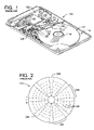
- FIG. 1 is a diagrammatic representation of a conventional disk drive with its top cover removed;
- FIG. 2 is a diagrammatic representation of a top view of a magnetic storage disk illustrating a typical organization of data
- FIG. 3A is a graph of PES frequency distribution during head touchdown
- FIG. 3B is a graph of PES frequency distribution during track following
- FIG. 4A is a graph corresponding to FIG. 3A at the lower frequencies
- FIG. 4B is a graph corresponding to FIG. 3B at the lower frequencies
- FIG. 5A is a graph of PES convergence at one-half the disk rotation frequency for multiple disk revolutions during head touchdown
- FIG. 5B is a graph of PES convergence at one-half the disk rotation frequency for multiple disk revolutions during track following;
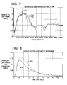
- FIG. 6 is a graph of PES as a function of heater power during head touchdown
- FIG. 7 is a graph of servo system transfer functions with different sensitivity
- FIG. 8 is a graph of modeled servo system response to a step input using different transfer functions during track following
- FIG. 9 is a graph of servo system frequency response using different transfer functions.
- FIG. 10 is a graph of PES variance as a function of write current using different transfer functions.
- FIG. 1 illustrates a conventional disk drive 110 that includes a magnetic storage disk 112 that is rotated by a spindle motor 114 .
- the spindle motor 114 is mounted on a base plate 116 .
- An actuator arm assembly 118 is also mounted on the base plate 116 .
- the actuator arm assembly 118 includes a read/write head 120 mounted on a flexure arm 122 which is attached to an actuator arm 124 that rotates about a bearing assembly 126 .
- the actuator arm assembly 118 also contains a voice coil motor 128 which moves the head 120 relative to the disk 112 .
- the spindle motor 114 , the head 120 and the voice coil motor 128 are coupled to electronic circuits 130 mounted on a printed circuit board 132 .
- the electronic circuits 130 include a read channel, a microprocessor-based controller and a random access memory (RAM).
- the disk drive 110 typically includes multiple disks 112 and therefore multiple actuator arm assemblies 118 .
- the disk drive 110 can include a single disk 112 and a single actuator arm assembly 118 .
- FIG. 2 illustrates the disk 112 with a typical organization of data.
- the disk 112 includes concentric data storage tracks 242 for storing data.
- the tracks 242 are illustrated as centerlines, however the tracks 242 each occupy a finite width about a corresponding centerline.
- the disk 112 also includes radially-aligned servo spokes (or wedges) 244 that cross the tracks 242 and store servo information in servo sectors in the tracks 242 .
- the servo information is read by the head 120 during read and write operations to position the head 120 above a desired track 242 .
- the disk 112 also includes customer data regions 246 between the servo spokes 244 that cross the tracks 242 and store customer data in data sectors in the tracks 242 .
- the present invention takes advantage of one or more distinctive PES frequencies during head touchdown to detect head touchdown with improved signal-to-noise ratio.
- a PES frequency at one-half the disk rotation frequency (0.5 F) can achieve a signal-to-noise ratio of about 50 (or more).
- a PES frequency or additional PES frequencies at harmonics such as 1.0 F, 1.5 F and 2.0 F can be used.
- FIGS. 3A , 3 B, 4 A and 4 B show graphs of PES frequency distribution obtained using a fast Fourier transform (FFT).
- FIGS. 3A and 4A show PES frequency distributions during head touchdown
- FIGS. 3B and 4B show PES frequency distributions during track following.
- FIGS. 3A and 3B have a frequency range of 0 to 12,000 Hz
- FIGS. 4A and 4B show the lower frequency range of 0 to 1200 Hz in FIGS. 3A and 3B , respectively.
- the PES magnitude is determined by digital-to-analog converter (DAC) counts.
- DAC digital-to-analog converter
- FIGS. 3A , 3 B, 4 A and 4 B indicate that the PES has a greater power concentration in the lower frequencies during head touchdown than during track following.
- FIG. 4A shows head touchdown characterized by peaks at 0.5 F ( 412 a ), 1 F ( 412 b ) and 1.5 F ( 412 c ), and the 0.5 F peak ( 412 a ) has the largest magnitude.
- Head touchdown is detected by monitoring for peaks or increases in the PES at particular frequencies or frequency ranges, particularly at frequencies substantially equal to the frequency at which bias which increases the PES magnitude is injected into the servo system by a heater in the head.
- the changes or peaks in PES power at particular frequencies can be measured in a wide variety of ways.
- disk drives that apply a single point discrete Fourier transform (DFT) to the PES for adaptive runout correction can also apply the single point DFT to the PES for head touchdown detection with little or no additional computation time and relatively little firmware modification.
- the single point DFT can calculate the sine and cosine coefficients in each servo interrupt service request so that head touchdown is detected in real time rather than post-process.
- the heater can be turned off whenever the 0.5 F PES magnitude is greater than a predetermined threshold (even before reaching 4 disk revolutions).
- head touchdown detection may require adjusting the single point DFT.
- FIGS. 5A and 5B are graphs of PES convergence at one-half the disk rotation frequency for multiple test runs through 22 disk revolutions during head touchdown ( FIG. 5A ) and track following ( FIG. 5B ).
- the PES converges in about 20 disk revolutions. Because the PES magnitude at 0.5 F during track following is relatively small, it is possible to detect head touchdown before the coefficients settle. In some instances, the PES magnitude at 0.5 F is sufficient to detect head touchdown within 4 disk revolutions.
- FIG. 6 is a graph of PES at one-half the disk rotation frequency as a function of heater power through 4 disk revolutions during head touchdown.
- the PES magnitude has a distinct increase at the threshold 612 as the heater power increases.
- the present invention improves head touchdown detection by adjusting the transfer function of the servo system.
- a transfer function with low vibration sensitivity reduces track misregistration during read and write operations but is counterproductive during head touchdown detection.
- a transfer function with high vibration sensitivity enables accurate head touchdown detection but causes track misregistration during read and write operations.
- the present invention solves this problem by using a first transfer function with low vibration sensitivity during read and write operations and a second transfer function with high vibration sensitivity during head touchdown detection.
- the transfer functions can be adjusted to have different vibration sensitivities in a wide variety of ways.
- H2/Hinfinity-based optimization which forms the weighting function based on the objectives
- a cost function based, random searching technique with the cost function objective being to maximize the ratio of PES shock to PES on-track can be used.
- FIG. 7 is a graph of servo system transfer functions with different sensitivity.
- the transfer functions are defined by a ratio of error to on-track (unitless) as a function of frequency.
- a head touchdown transfer function 712 , measured transfer function 714 and modeled transfer function 716 are shown.
- the head touchdown transfer function 712 has higher attenuation than the transfer functions 714 and 716 below a cut-off frequency of about 1000 Hz and higher amplification than the transfer functions 714 and 716 between about 1200 Hz and about 2400 Hz.
- FIG. 8 is a graph of modeled servo system response to a step input using different transfer functions during track following.
- the response 812 is obtained using the head touchdown transfer function 712
- the response 814 is obtained using a less sensitive transfer function.
- the response 812 yields about 25 percent higher sensitivity to external disturbance than the response 814 .
- the head touchdown transfer function 712 is expected to attenuate the PES less than the measured transfer function 714 during head touchdown, whereas the measured transfer function 714 is expected to provide acceptable on-track performance during read and write operations.
- FIG. 9 is a graph of servo system frequency response (in decibels) as a function of frequency (on a logarithmic scale).
- the frequency response 912 is obtained using the head touchdown transfer function 712
- the frequency response 914 is obtained using a less sensitive transfer function.
- FIG. 10 is a graph of PES variance as a function of write current using different transfer functions.
- the PES variance 1012 is obtained using the head touchdown transfer function 712
- the PES variance 1014 is obtained using a less sensitive transfer function. Head touchdown detection using PES variance is facilitated using the transfer function 712 .
- This present invention can provide rapid head touchdown detection, preferably requiring less than about 50 disk revolutions, more preferably less than about 10 disk revolutions, more preferably less than about 6 disk revolutions, and even more preferably with as few as 2 to 4 disk revolutions.
- head touchdown can be detected based on PES peaks at certain frequencies (or combinations thereof) without adjusting the vibration sensitivity of the servo system.
- head touchdown can be detected in other data storage devices with magnetic disks, compact disks, digital versatile disks and optical systems.
- the signal related to head tracking that is measured at a discrete frequency to detect head touchdown can be an integration (nulli) signal, a head velocity signal, a bias current signal and combinations thereof.
- the PES magnitude has been measured with a power-frequency spectrum using a Fourier transform, the PES magnitude can be measured with other analyses or transformations that achieve the desired discrimination of head touchdown from vibration or other phenomena.
- the PES has been measured at a discrete frequency to detect head touchdown
- the PES can be measured at multiple discrete frequencies in frequency bands that include harmonics and/or subharmonics of a root frequency such as one-half the disk rotation frequency, and head touchdown can be detected using the multiple discrete frequencies.
- frequencies below the disk rotation frequency such as 0.5 F
- the disk drive can detect head touchdown in the context of fly height adjustment or preventing excessive pole tip protrusion.
- the disk drive can also detect head touchdown during factory calibration, upon boot-up, at periodic intervals, in response to a threshold number of errors, or in response to environmental changes such as temperature and pressure changes.
- the disk drive can also detect head touchdown as part of an error recovery procedure. For example, in a write recovery table, head touchdown can be detected in test tracks to reveal a touchdown-induced error.
- the discrete frequency can be set to the heater frequency or harmonics or subharmonics thereof.
- the heater frequency can be set to the disk rotation frequency or harmonics or subharmonics thereof.
- the heater can be cycled at alternate disk revolutions (heater turned on for one disk revolution, heater turned off for one disk revolution) and the discrete frequency can be set to the heater frequency (0.5 F).
- the heater can be cycled at 1 ⁇ 4 disk revolutions (heater turned on for 1 ⁇ 8 disk revolution, heater turned off for 1 ⁇ 8 disk revolution) and the discrete frequency can be set to the heater frequency at the fourth harmonic (4F).
- the first transfer function can suppress vibration, and the second transfer function can permit vibration. Therefore, even if the first transfer function suppresses head touchdown, the first transfer function is disabled and the second transfer function is enabled during head touchdown detection.
Abstract
Description
Claims (130)
Priority Applications (1)
| Application Number | Priority Date | Filing Date | Title |
|---|---|---|---|
| US10/984,559 US7158325B1 (en) | 2003-11-06 | 2004-11-08 | Disk drive head touchdown detection with improved discrimination |
Applications Claiming Priority (3)
| Application Number | Priority Date | Filing Date | Title |
|---|---|---|---|
| US51781503P | 2003-11-06 | 2003-11-06 | |
| US52693603P | 2003-12-04 | 2003-12-04 | |
| US10/984,559 US7158325B1 (en) | 2003-11-06 | 2004-11-08 | Disk drive head touchdown detection with improved discrimination |
Publications (1)
| Publication Number | Publication Date |
|---|---|
| US7158325B1 true US7158325B1 (en) | 2007-01-02 |
Family
ID=37592328
Family Applications (1)
| Application Number | Title | Priority Date | Filing Date |
|---|---|---|---|
| US10/984,559 Expired - Fee Related US7158325B1 (en) | 2003-11-06 | 2004-11-08 | Disk drive head touchdown detection with improved discrimination |
Country Status (1)
| Country | Link |
|---|---|
| US (1) | US7158325B1 (en) |
Cited By (47)
| Publication number | Priority date | Publication date | Assignee | Title |
|---|---|---|---|---|
| US20070236821A1 (en) * | 2006-04-10 | 2007-10-11 | Iomega Corporation | Detecting head/disk contact in a disk drive using a calibration parameter |
| US20070291401A1 (en) * | 2006-05-19 | 2007-12-20 | Maxtor Corporation | Contact detection using calibrated seeks |
| US7362534B1 (en) | 2004-04-08 | 2008-04-22 | Maxtor Corporation | System for detecting a change in head-to-disk contact status in a disk drive |
| US7411389B1 (en) | 2004-04-08 | 2008-08-12 | Maxtor Corporation | Method of detecting changes in operability status of a slider mover in a disk drive |
| EP1959438A2 (en) * | 2007-02-16 | 2008-08-20 | Samsung Electronics Co., Ltd. | Hard disk drive apparatus, method of control of the flying height of the magnetic head thereof, and a recording medium comprising a computer program for carrying out the method |
| US20080298197A1 (en) * | 2007-06-01 | 2008-12-04 | Seagate Technology, Llc | Controlling a heat resistive element with a pulse modulated signal |
| US7508618B1 (en) * | 2007-12-27 | 2009-03-24 | Hitachi Global Storage Tech Nl | Multivariate head-to-disk contact detection |
| US7518813B1 (en) * | 2004-06-07 | 2009-04-14 | Maxtor Corporation | Methods and structure for detecting anomalous events in a disk drive using VGA variance |
| US20090128947A1 (en) * | 2007-11-15 | 2009-05-21 | Western Digital (Fremont), Llc | Disk drive determining operating fly height by detecting head disk contact from disk rotation time |
| US7551390B1 (en) | 2007-08-21 | 2009-06-23 | Western Digital Technologies, Inc. | Disk drive to characterize misaligned servo wedges |
| US20090175147A1 (en) * | 2008-01-08 | 2009-07-09 | Samsung Electronics Co., Ltd. | Reducing written-in errors in servo patterns |
| US20090195936A1 (en) * | 2008-02-04 | 2009-08-06 | Western Digital Technologies, Inc. | Disk drive servoing off of first head while determining fly height for second head |
| US20100033860A1 (en) * | 2008-08-06 | 2010-02-11 | Tomita Craig L | Proximity Detection Method For Magnetic Head And Recording Medium |
| US7675707B1 (en) | 2008-11-21 | 2010-03-09 | Western Digital Technologies, Inc. | Disk drive employing repeatable disturbance compensation for fly height control |
| US20100202082A1 (en) * | 2008-07-28 | 2010-08-12 | Nils Graef | Systems and Methods for Variable Fly Height Measurement |
| US7796356B1 (en) | 2009-05-04 | 2010-09-14 | Western Digital (Fremont), Llc | Head integrated touchdown sensor for hard disk drives |
| US7800858B1 (en) | 2009-05-04 | 2010-09-21 | Western Digital (Fremont), Llc | Differential head integrated touchdown sensors for hard disk drives |
| US7839595B1 (en) | 2008-01-25 | 2010-11-23 | Western Digital Technologies, Inc. | Feed forward compensation for fly height control in a disk drive |
| US20100309521A1 (en) * | 1998-03-27 | 2010-12-09 | Canon Kabushiki Kaisha | Image processing apparatus, control method of image processing apparatus, and storage medium storing therein control program for image processing apparatus |
| US20110013305A1 (en) * | 2009-07-16 | 2011-01-20 | Ehrlich Richard M | Proximity detection method for magnetic head and recording medium |
| US7916420B1 (en) | 2010-05-14 | 2011-03-29 | Western Digital Technologies, Inc. | Disk drive employing comb filter for repeatable fly height compensation |
| US7974039B1 (en) | 2009-06-17 | 2011-07-05 | Western Digital Technology, Inc. | Disk drive to reduce head instability |
| US8059357B1 (en) | 2010-03-18 | 2011-11-15 | Western Digital Technologies, Inc. | Disk drive adjusting fly height when calibrating head/disk contact |
| US8139310B1 (en) | 2010-01-06 | 2012-03-20 | Western Digital Technologies, Inc. | Fly height sensor control circuit |
| US20120218659A1 (en) * | 2011-02-28 | 2012-08-30 | Seagate Technology Llc | Contact detection |
| US8300338B1 (en) | 2010-09-30 | 2012-10-30 | Western Digital Technologies, Inc. | Disk drive correlating different fly height measurements to verify disk warpage |
| US8300349B2 (en) | 2010-08-05 | 2012-10-30 | Lsi Corporation | Systems and methods for format efficient calibration for servo data based harmonics calculation |
| US8320069B1 (en) | 2010-03-18 | 2012-11-27 | Western Digital Technologies, Inc. | Disk drive detecting positive correlation in fly height measurements |
| US8325432B2 (en) | 2010-08-05 | 2012-12-04 | Lsi Corporation | Systems and methods for servo data based harmonics calculation |
| US8345373B2 (en) | 2010-08-16 | 2013-01-01 | Lsi Corporation | Systems and methods for phase offset based spectral aliasing compensation |
| US8482873B1 (en) | 2008-02-18 | 2013-07-09 | Western Digital Technologies, Inc. | Disk drive employing pulse width modulation of head control signal |
| US8526133B2 (en) | 2011-07-19 | 2013-09-03 | Lsi Corporation | Systems and methods for user data based fly height calculation |
| US8593753B1 (en) | 2010-04-22 | 2013-11-26 | Western Digital Technologies, Inc. | Touchdown detection |
| US8605381B2 (en) | 2010-09-03 | 2013-12-10 | Lsi Corporation | Systems and methods for phase compensated harmonic sensing in fly height control |
| US8681445B1 (en) | 2012-06-28 | 2014-03-25 | Western Digital Technologies, Inc. | Disk drive detecting head touchdown by computing anti-correlation in sensor signal |
| US8699173B1 (en) * | 2011-09-01 | 2014-04-15 | Western Digital Technologies, Inc. | Disk drive detecting touchdown event by evaluating frequency response of a touchdown metric |
| US8755136B1 (en) | 2012-04-18 | 2014-06-17 | Western Digital Technologies, Inc. | Systems and methods for storage device read/write head malfunction detection |
| US8817406B2 (en) | 2011-12-30 | 2014-08-26 | HGST Netherlands B.V. | Magnetic-recording head with touch-down detector incorporating a carbon nano-tube |
| US8854756B1 (en) | 2013-05-10 | 2014-10-07 | Lsi Corporation | Systems and methods for mitigating data interference in a contact signal |
| US8885279B1 (en) | 2010-08-30 | 2014-11-11 | Western Digital Technologies, Inc. | Disk drive detecting head/disk contact by evaluating a subset of touchdown metrics during a servo sector interrupt |
| US8934192B1 (en) | 2008-11-24 | 2015-01-13 | Western Digital Technologies, Inc. | Disk drive determining operating fly height by detecting head disk contact from read signal amplitude variance |
| US8937781B1 (en) | 2013-12-16 | 2015-01-20 | Lsi Corporation | Constant false alarm resonance detector |
| US8970978B1 (en) | 2012-10-22 | 2015-03-03 | Western Digital Technologies, Inc. | Disk drive detecting head touchdown by applying DC+AC control signal to fly height actuator |
| US9129632B1 (en) | 2014-10-27 | 2015-09-08 | Avago Technologies General Ip (Singapore) Pte. Ltd. | Loop pulse estimation-based fly height detector |
| US9349401B1 (en) | 2014-07-24 | 2016-05-24 | Western Digital Technologies, Inc. | Electronic system with media scan mechanism and method of operation thereof |
| US9437234B1 (en) | 2015-08-20 | 2016-09-06 | Seagate Technology Llc | Head-medium contact detection using high frequency heater oscillation |
| US9761270B1 (en) | 2016-12-21 | 2017-09-12 | Seagate Technology Llc | Data storage device using high and low frequencies AC heat produce position-error-signals for head contact detection |
Citations (9)
| Publication number | Priority date | Publication date | Assignee | Title |
|---|---|---|---|---|
| US5545989A (en) * | 1995-01-19 | 1996-08-13 | Conner Peripherals, Inc. | Non-destructive in-situ landing velocity determination of magnetic rigid disk drives using back EMF from the spindle motor during shutdown |
| US5594595A (en) * | 1995-01-19 | 1997-01-14 | Conner Peripherals, Inc. | FM detection of slider-disk interface |
| US5742446A (en) * | 1995-11-08 | 1998-04-21 | Seagate Technology, Inc. | Method for detection of slider-disk contact |
| US5824920A (en) * | 1995-10-27 | 1998-10-20 | Fujitsu Limited | Apparatus for evaluating magnetic recording medium |
| US6097559A (en) * | 1998-06-26 | 2000-08-01 | International Business Machines Corporation | System and method for detecting head-to-disk contact in-situ a direct access storage device using a position error signal |
| US6164118A (en) * | 1998-09-30 | 2000-12-26 | Komag Incorporated | Calibration disk having discrete bands of calibration bumps |
| US20030193727A1 (en) * | 2002-04-11 | 2003-10-16 | Seagate Technology Llc | Detecting head-disc interference using position error signal |
| US6678108B2 (en) * | 2001-05-14 | 2004-01-13 | International Business Machines Corporation | Method and apparatus for identifying spindle imbalance in a hard disk drive |
| US6747824B1 (en) * | 2000-05-26 | 2004-06-08 | Hitachi Global Storage Technologies Netherlands, B.V. | Method and apparatus for head crash predictive failure analysis based upon slider track misregistration measurement using the readback signal |
-
2004
- 2004-11-08 US US10/984,559 patent/US7158325B1/en not_active Expired - Fee Related
Patent Citations (9)
| Publication number | Priority date | Publication date | Assignee | Title |
|---|---|---|---|---|
| US5545989A (en) * | 1995-01-19 | 1996-08-13 | Conner Peripherals, Inc. | Non-destructive in-situ landing velocity determination of magnetic rigid disk drives using back EMF from the spindle motor during shutdown |
| US5594595A (en) * | 1995-01-19 | 1997-01-14 | Conner Peripherals, Inc. | FM detection of slider-disk interface |
| US5824920A (en) * | 1995-10-27 | 1998-10-20 | Fujitsu Limited | Apparatus for evaluating magnetic recording medium |
| US5742446A (en) * | 1995-11-08 | 1998-04-21 | Seagate Technology, Inc. | Method for detection of slider-disk contact |
| US6097559A (en) * | 1998-06-26 | 2000-08-01 | International Business Machines Corporation | System and method for detecting head-to-disk contact in-situ a direct access storage device using a position error signal |
| US6164118A (en) * | 1998-09-30 | 2000-12-26 | Komag Incorporated | Calibration disk having discrete bands of calibration bumps |
| US6747824B1 (en) * | 2000-05-26 | 2004-06-08 | Hitachi Global Storage Technologies Netherlands, B.V. | Method and apparatus for head crash predictive failure analysis based upon slider track misregistration measurement using the readback signal |
| US6678108B2 (en) * | 2001-05-14 | 2004-01-13 | International Business Machines Corporation | Method and apparatus for identifying spindle imbalance in a hard disk drive |
| US20030193727A1 (en) * | 2002-04-11 | 2003-10-16 | Seagate Technology Llc | Detecting head-disc interference using position error signal |
Cited By (70)
| Publication number | Priority date | Publication date | Assignee | Title |
|---|---|---|---|---|
| US20100309521A1 (en) * | 1998-03-27 | 2010-12-09 | Canon Kabushiki Kaisha | Image processing apparatus, control method of image processing apparatus, and storage medium storing therein control program for image processing apparatus |
| US7362534B1 (en) | 2004-04-08 | 2008-04-22 | Maxtor Corporation | System for detecting a change in head-to-disk contact status in a disk drive |
| US7411389B1 (en) | 2004-04-08 | 2008-08-12 | Maxtor Corporation | Method of detecting changes in operability status of a slider mover in a disk drive |
| US7486459B1 (en) | 2004-04-08 | 2009-02-03 | Maxtor Corporation | Disk drive with performance driven head-to-disk spacing |
| US7509728B1 (en) * | 2004-04-08 | 2009-03-31 | Maxtor Corporation | Method for adjusting head-to-disk spacing in a disk drive |
| US7518813B1 (en) * | 2004-06-07 | 2009-04-14 | Maxtor Corporation | Methods and structure for detecting anomalous events in a disk drive using VGA variance |
| US7423830B2 (en) * | 2006-04-10 | 2008-09-09 | Iomega Corporation | Detecting head/disk contact in a disk drive using a calibration parameter |
| US20070236821A1 (en) * | 2006-04-10 | 2007-10-11 | Iomega Corporation | Detecting head/disk contact in a disk drive using a calibration parameter |
| US20070291401A1 (en) * | 2006-05-19 | 2007-12-20 | Maxtor Corporation | Contact detection using calibrated seeks |
| EP1959438A2 (en) * | 2007-02-16 | 2008-08-20 | Samsung Electronics Co., Ltd. | Hard disk drive apparatus, method of control of the flying height of the magnetic head thereof, and a recording medium comprising a computer program for carrying out the method |
| US8159771B2 (en) | 2007-06-01 | 2012-04-17 | Seagate Technology Llc | Controlling a heat resistive element with a pulse modulated signal |
| US20080298197A1 (en) * | 2007-06-01 | 2008-12-04 | Seagate Technology, Llc | Controlling a heat resistive element with a pulse modulated signal |
| US7551390B1 (en) | 2007-08-21 | 2009-06-23 | Western Digital Technologies, Inc. | Disk drive to characterize misaligned servo wedges |
| US20090128947A1 (en) * | 2007-11-15 | 2009-05-21 | Western Digital (Fremont), Llc | Disk drive determining operating fly height by detecting head disk contact from disk rotation time |
| US7583466B2 (en) | 2007-11-15 | 2009-09-01 | Western Digital (Fremont), Llc | Disk drive determining operating fly height by detecting head disk contact from disk rotation time |
| US7508618B1 (en) * | 2007-12-27 | 2009-03-24 | Hitachi Global Storage Tech Nl | Multivariate head-to-disk contact detection |
| US20090175147A1 (en) * | 2008-01-08 | 2009-07-09 | Samsung Electronics Co., Ltd. | Reducing written-in errors in servo patterns |
| US8169732B2 (en) * | 2008-01-08 | 2012-05-01 | Shepherd Stanley H | Reducing written-in errors in servo patterns |
| US7839595B1 (en) | 2008-01-25 | 2010-11-23 | Western Digital Technologies, Inc. | Feed forward compensation for fly height control in a disk drive |
| US7630162B2 (en) | 2008-02-04 | 2009-12-08 | Western Digital Technologies, Inc. | Disk drive servoing off of first head while determining fly height for second head |
| US20090195936A1 (en) * | 2008-02-04 | 2009-08-06 | Western Digital Technologies, Inc. | Disk drive servoing off of first head while determining fly height for second head |
| US8780473B1 (en) | 2008-02-04 | 2014-07-15 | Western Digital Technologies, Inc. | Disk drive selecting a global digital-to-analog setting for a plurality of heads |
| US8482873B1 (en) | 2008-02-18 | 2013-07-09 | Western Digital Technologies, Inc. | Disk drive employing pulse width modulation of head control signal |
| US20100202082A1 (en) * | 2008-07-28 | 2010-08-12 | Nils Graef | Systems and Methods for Variable Fly Height Measurement |
| US8503128B2 (en) | 2008-07-28 | 2013-08-06 | Agere Systems Inc. | Systems and methods for variable compensated fly height measurement |
| US8098451B2 (en) | 2008-07-28 | 2012-01-17 | Agere Systems Inc. | Systems and methods for variable fly height measurement |
| US7990641B2 (en) * | 2008-08-06 | 2011-08-02 | Kabushiki Kaisha Toshiba | Proximity detection method for magnetic head and recording medium |
| US20100321812A1 (en) * | 2008-08-06 | 2010-12-23 | Kabushiki Kaisha Toshiba | Proximity detection method for magnetic head and recording medium |
| US20100033860A1 (en) * | 2008-08-06 | 2010-02-11 | Tomita Craig L | Proximity Detection Method For Magnetic Head And Recording Medium |
| US7675707B1 (en) | 2008-11-21 | 2010-03-09 | Western Digital Technologies, Inc. | Disk drive employing repeatable disturbance compensation for fly height control |
| US8934192B1 (en) | 2008-11-24 | 2015-01-13 | Western Digital Technologies, Inc. | Disk drive determining operating fly height by detecting head disk contact from read signal amplitude variance |
| US7796356B1 (en) | 2009-05-04 | 2010-09-14 | Western Digital (Fremont), Llc | Head integrated touchdown sensor for hard disk drives |
| US7800858B1 (en) | 2009-05-04 | 2010-09-21 | Western Digital (Fremont), Llc | Differential head integrated touchdown sensors for hard disk drives |
| US7974039B1 (en) | 2009-06-17 | 2011-07-05 | Western Digital Technology, Inc. | Disk drive to reduce head instability |
| JP2011023094A (en) * | 2009-07-16 | 2011-02-03 | Toshiba Corp | Method for detecting touchdown between magnetic head and recording medium |
| US20110013305A1 (en) * | 2009-07-16 | 2011-01-20 | Ehrlich Richard M | Proximity detection method for magnetic head and recording medium |
| US8018669B2 (en) * | 2009-07-16 | 2011-09-13 | Kabushiki Kaisha Toshiba | Proximity detection method for magnetic head and recording medium |
| US8004788B2 (en) | 2009-07-16 | 2011-08-23 | Kabushiki Kaisha Toshiba | Proximity detection method for magnetic head and recording medium |
| US8203802B2 (en) | 2009-07-16 | 2012-06-19 | Kabushiki Kaisha Toshiba | Proximity detection method for magnetic head and recording medium |
| US20110141601A1 (en) * | 2009-07-16 | 2011-06-16 | Kabushiki Kaisha Toshiba | Proximity detection method for magnetic head and recording medium |
| US8139310B1 (en) | 2010-01-06 | 2012-03-20 | Western Digital Technologies, Inc. | Fly height sensor control circuit |
| US8279550B1 (en) | 2010-01-06 | 2012-10-02 | Western Digital Technologies, Inc. | Fly height sensor control circuit |
| US8320069B1 (en) | 2010-03-18 | 2012-11-27 | Western Digital Technologies, Inc. | Disk drive detecting positive correlation in fly height measurements |
| US8059357B1 (en) | 2010-03-18 | 2011-11-15 | Western Digital Technologies, Inc. | Disk drive adjusting fly height when calibrating head/disk contact |
| US8593753B1 (en) | 2010-04-22 | 2013-11-26 | Western Digital Technologies, Inc. | Touchdown detection |
| US7916420B1 (en) | 2010-05-14 | 2011-03-29 | Western Digital Technologies, Inc. | Disk drive employing comb filter for repeatable fly height compensation |
| US8300349B2 (en) | 2010-08-05 | 2012-10-30 | Lsi Corporation | Systems and methods for format efficient calibration for servo data based harmonics calculation |
| US8325432B2 (en) | 2010-08-05 | 2012-12-04 | Lsi Corporation | Systems and methods for servo data based harmonics calculation |
| US8345373B2 (en) | 2010-08-16 | 2013-01-01 | Lsi Corporation | Systems and methods for phase offset based spectral aliasing compensation |
| US8885279B1 (en) | 2010-08-30 | 2014-11-11 | Western Digital Technologies, Inc. | Disk drive detecting head/disk contact by evaluating a subset of touchdown metrics during a servo sector interrupt |
| US8605381B2 (en) | 2010-09-03 | 2013-12-10 | Lsi Corporation | Systems and methods for phase compensated harmonic sensing in fly height control |
| US8300338B1 (en) | 2010-09-30 | 2012-10-30 | Western Digital Technologies, Inc. | Disk drive correlating different fly height measurements to verify disk warpage |
| US9135938B2 (en) * | 2011-02-28 | 2015-09-15 | Seagate Technology Llc | Contact detection |
| US20140254344A1 (en) * | 2011-02-28 | 2014-09-11 | Seagate Technology Llc | Contact Detection |
| US8730611B2 (en) * | 2011-02-28 | 2014-05-20 | Seagate Technology Llc | Contact detection |
| US20120218659A1 (en) * | 2011-02-28 | 2012-08-30 | Seagate Technology Llc | Contact detection |
| US8526133B2 (en) | 2011-07-19 | 2013-09-03 | Lsi Corporation | Systems and methods for user data based fly height calculation |
| US8699173B1 (en) * | 2011-09-01 | 2014-04-15 | Western Digital Technologies, Inc. | Disk drive detecting touchdown event by evaluating frequency response of a touchdown metric |
| US8817406B2 (en) | 2011-12-30 | 2014-08-26 | HGST Netherlands B.V. | Magnetic-recording head with touch-down detector incorporating a carbon nano-tube |
| US8755136B1 (en) | 2012-04-18 | 2014-06-17 | Western Digital Technologies, Inc. | Systems and methods for storage device read/write head malfunction detection |
| US8681445B1 (en) | 2012-06-28 | 2014-03-25 | Western Digital Technologies, Inc. | Disk drive detecting head touchdown by computing anti-correlation in sensor signal |
| US8970978B1 (en) | 2012-10-22 | 2015-03-03 | Western Digital Technologies, Inc. | Disk drive detecting head touchdown by applying DC+AC control signal to fly height actuator |
| US9293164B2 (en) | 2013-05-10 | 2016-03-22 | Avago Technologies General Ip (Singapore) Pte. Ltd. | Systems and methods for energy based head contact detection |
| US8854756B1 (en) | 2013-05-10 | 2014-10-07 | Lsi Corporation | Systems and methods for mitigating data interference in a contact signal |
| US8937781B1 (en) | 2013-12-16 | 2015-01-20 | Lsi Corporation | Constant false alarm resonance detector |
| US9349401B1 (en) | 2014-07-24 | 2016-05-24 | Western Digital Technologies, Inc. | Electronic system with media scan mechanism and method of operation thereof |
| US9129632B1 (en) | 2014-10-27 | 2015-09-08 | Avago Technologies General Ip (Singapore) Pte. Ltd. | Loop pulse estimation-based fly height detector |
| US9437234B1 (en) | 2015-08-20 | 2016-09-06 | Seagate Technology Llc | Head-medium contact detection using high frequency heater oscillation |
| US9761270B1 (en) | 2016-12-21 | 2017-09-12 | Seagate Technology Llc | Data storage device using high and low frequencies AC heat produce position-error-signals for head contact detection |
| US10147451B2 (en) | 2016-12-21 | 2018-12-04 | Seagate Technology Llc | Data storage device with high signal-to-noise ratio contact detection |
Similar Documents
| Publication | Publication Date | Title |
|---|---|---|
| US7158325B1 (en) | Disk drive head touchdown detection with improved discrimination | |
| US7196864B1 (en) | Disk drive having a servo control system optimized for faster determination of repeatable runout correction values and related method | |
| US6952318B1 (en) | Scaling linear vibration sensor data in disk drive | |
| KR100418740B1 (en) | Method for detecting abnormal magnetic head fly height, method for data writing and hard disk drive apparatus | |
| US7595954B1 (en) | Disk drive to estimate repeatable runout (RRO) based upon on an optimal mean square estimation (MSE) learning method | |
| US7817372B2 (en) | Head flying height control method, write current value determining method, and storage device | |
| US7511914B2 (en) | Fly height compensation using temperature and non-repeatable runouts | |
| US7227708B2 (en) | System and method for determining long-range erasure of adjacent tracks in hard disk drive | |
| US20050237654A1 (en) | Methods for variable multi-pass servowriting and self-servowriting | |
| KR100413766B1 (en) | Servo defect management scheme in hard disk drives | |
| US7990641B2 (en) | Proximity detection method for magnetic head and recording medium | |
| US7251097B2 (en) | Written-in error compensation method for coherent repeatable runout | |
| US6751046B1 (en) | Writing servo data patterns on a data storage disk to account for repeatable and non-repeatable disturbances and thereby provide concentric data tracks | |
| KR19990065701A (en) | How to use the repeatable runout compensation algorithm | |
| US8139308B2 (en) | Hard disk drive, method of controlling flying height of magnetic head thereof, and recording medium containing computer program thereon | |
| US7190546B2 (en) | Systems using extended servo patterns with variable multi-pass servowriting and self-servowriting | |
| WO2000016332A1 (en) | Concentric spacing of virtual data tracks using run-out compensation | |
| US20100208387A1 (en) | Fly-Height Management Via Harmonic Sensing | |
| KR20130010829A (en) | Systems and methods for user data based fly height calculation | |
| KR100712559B1 (en) | Method and apparatus for adjusting frequency of reference clock and disc drive using the same | |
| US6785073B2 (en) | Identification and cancellation of cage frequency in a hard disc drive | |
| US20090034109A1 (en) | Disk drive apparatus and media defect detection method | |
| US6963466B2 (en) | Radial dependent low frequency repeatable run out compensation apparatus and method | |
| US20030193727A1 (en) | Detecting head-disc interference using position error signal | |
| US20020186494A1 (en) | Magnetic disk device and servo write method |
Legal Events
| Date | Code | Title | Description |
|---|---|---|---|
| AS | Assignment |
Owner name: MAXTOR CORPORATION, COLORADO Free format text: ASSIGNMENT OF ASSIGNORS INTEREST;ASSIGNORS:HU, XIAOPING;SUN, YU;GUO, LIN;AND OTHERS;REEL/FRAME:016294/0447;SIGNING DATES FROM 20050125 TO 20050208 |
|
| AS | Assignment |
Owner name: JPMORGAN CHASE BANK, N.A., AS ADMINISTRATIVE AGENT Free format text: SECURITY AGREEMENT;ASSIGNORS:MAXTOR CORPORATION;SEAGATE TECHNOLOGY LLC;SEAGATE TECHNOLOGY INTERNATIONAL;REEL/FRAME:022757/0017 Effective date: 20090507 Owner name: WELLS FARGO BANK, NATIONAL ASSOCIATION, AS COLLATE Free format text: SECURITY AGREEMENT;ASSIGNORS:MAXTOR CORPORATION;SEAGATE TECHNOLOGY LLC;SEAGATE TECHNOLOGY INTERNATIONAL;REEL/FRAME:022757/0017 Effective date: 20090507 |
|
| FPAY | Fee payment |
Year of fee payment: 4 |
|
| AS | Assignment |
Owner name: SEAGATE TECHNOLOGY HDD HOLDINGS, CALIFORNIA Free format text: RELEASE;ASSIGNOR:JPMORGAN CHASE BANK, N.A., AS ADMINISTRATIVE AGENT;REEL/FRAME:025662/0001 Effective date: 20110114 Owner name: SEAGATE TECHNOLOGY LLC, CALIFORNIA Free format text: RELEASE;ASSIGNOR:JPMORGAN CHASE BANK, N.A., AS ADMINISTRATIVE AGENT;REEL/FRAME:025662/0001 Effective date: 20110114 Owner name: MAXTOR CORPORATION, CALIFORNIA Free format text: RELEASE;ASSIGNOR:JPMORGAN CHASE BANK, N.A., AS ADMINISTRATIVE AGENT;REEL/FRAME:025662/0001 Effective date: 20110114 Owner name: SEAGATE TECHNOLOGY INTERNATIONAL, CALIFORNIA Free format text: RELEASE;ASSIGNOR:JPMORGAN CHASE BANK, N.A., AS ADMINISTRATIVE AGENT;REEL/FRAME:025662/0001 Effective date: 20110114 |
|
| AS | Assignment |
Owner name: THE BANK OF NOVA SCOTIA, AS ADMINISTRATIVE AGENT, Free format text: SECURITY AGREEMENT;ASSIGNOR:SEAGATE TECHNOLOGY LLC;REEL/FRAME:026010/0350 Effective date: 20110118 |
|
| AS | Assignment |
Owner name: SEAGATE TECHNOLOGY INTERNATIONAL, CAYMAN ISLANDS Free format text: TERMINATION AND RELEASE OF SECURITY INTEREST IN PATENT RIGHTS;ASSIGNOR:WELLS FARGO BANK, NATIONAL ASSOCIATION, AS COLLATERAL AGENT AND SECOND PRIORITY REPRESENTATIVE;REEL/FRAME:030833/0001 Effective date: 20130312 Owner name: SEAGATE TECHNOLOGY LLC, CALIFORNIA Free format text: TERMINATION AND RELEASE OF SECURITY INTEREST IN PATENT RIGHTS;ASSIGNOR:WELLS FARGO BANK, NATIONAL ASSOCIATION, AS COLLATERAL AGENT AND SECOND PRIORITY REPRESENTATIVE;REEL/FRAME:030833/0001 Effective date: 20130312 Owner name: SEAGATE TECHNOLOGY US HOLDINGS, INC., CALIFORNIA Free format text: TERMINATION AND RELEASE OF SECURITY INTEREST IN PATENT RIGHTS;ASSIGNOR:WELLS FARGO BANK, NATIONAL ASSOCIATION, AS COLLATERAL AGENT AND SECOND PRIORITY REPRESENTATIVE;REEL/FRAME:030833/0001 Effective date: 20130312 Owner name: EVAULT INC. (F/K/A I365 INC.), CALIFORNIA Free format text: TERMINATION AND RELEASE OF SECURITY INTEREST IN PATENT RIGHTS;ASSIGNOR:WELLS FARGO BANK, NATIONAL ASSOCIATION, AS COLLATERAL AGENT AND SECOND PRIORITY REPRESENTATIVE;REEL/FRAME:030833/0001 Effective date: 20130312 |
|
| FPAY | Fee payment |
Year of fee payment: 8 |
|
| FEPP | Fee payment procedure |
Free format text: MAINTENANCE FEE REMINDER MAILED (ORIGINAL EVENT CODE: REM.); ENTITY STATUS OF PATENT OWNER: LARGE ENTITY |
|
| LAPS | Lapse for failure to pay maintenance fees |
Free format text: PATENT EXPIRED FOR FAILURE TO PAY MAINTENANCE FEES (ORIGINAL EVENT CODE: EXP.); ENTITY STATUS OF PATENT OWNER: LARGE ENTITY |
|
| STCH | Information on status: patent discontinuation |
Free format text: PATENT EXPIRED DUE TO NONPAYMENT OF MAINTENANCE FEES UNDER 37 CFR 1.362 |
|
| FP | Lapsed due to failure to pay maintenance fee |
Effective date: 20190102 |