US7158099B1 - Systems and methods for forming a reduced-glare image - Google Patents
Systems and methods for forming a reduced-glare image Download PDFInfo
- Publication number
- US7158099B1 US7158099B1 US10/377,405 US37740503A US7158099B1 US 7158099 B1 US7158099 B1 US 7158099B1 US 37740503 A US37740503 A US 37740503A US 7158099 B1 US7158099 B1 US 7158099B1
- Authority
- US
- United States
- Prior art keywords
- image
- person
- light source
- glare
- reduced
- Prior art date
- Legal status (The legal status is an assumption and is not a legal conclusion. Google has not performed a legal analysis and makes no representation as to the accuracy of the status listed.)
- Expired - Lifetime, expires
Links
- 238000000034 method Methods 0.000 title claims abstract description 33
- 230000004313 glare Effects 0.000 claims abstract description 44
- 238000005286 illumination Methods 0.000 claims abstract description 9
- 239000002131 composite material Substances 0.000 claims description 11
- 238000003384 imaging method Methods 0.000 description 11
- 230000001815 facial effect Effects 0.000 description 7
- 238000010586 diagram Methods 0.000 description 5
- 230000000694 effects Effects 0.000 description 4
- 239000011521 glass Substances 0.000 description 2
- 239000000470 constituent Substances 0.000 description 1
- 238000001514 detection method Methods 0.000 description 1
- 230000008921 facial expression Effects 0.000 description 1
- 238000005242 forging Methods 0.000 description 1
- 239000000463 material Substances 0.000 description 1
- 238000010186 staining Methods 0.000 description 1
- 238000006467 substitution reaction Methods 0.000 description 1
- 230000001360 synchronised effect Effects 0.000 description 1
- 210000003813 thumb Anatomy 0.000 description 1
Images


Classifications
-
- G—PHYSICS
- G03—PHOTOGRAPHY; CINEMATOGRAPHY; ANALOGOUS TECHNIQUES USING WAVES OTHER THAN OPTICAL WAVES; ELECTROGRAPHY; HOLOGRAPHY
- G03B—APPARATUS OR ARRANGEMENTS FOR TAKING PHOTOGRAPHS OR FOR PROJECTING OR VIEWING THEM; APPARATUS OR ARRANGEMENTS EMPLOYING ANALOGOUS TECHNIQUES USING WAVES OTHER THAN OPTICAL WAVES; ACCESSORIES THEREFOR
- G03B15/00—Special procedures for taking photographs; Apparatus therefor
- G03B15/02—Illuminating scene
- G03B15/03—Combinations of cameras with lighting apparatus; Flash units
-
- G—PHYSICS
- G06—COMPUTING; CALCULATING OR COUNTING
- G06T—IMAGE DATA PROCESSING OR GENERATION, IN GENERAL
- G06T5/00—Image enhancement or restoration
- G06T5/50—Image enhancement or restoration by the use of more than one image, e.g. averaging, subtraction
-
- G06T5/94—
-
- G—PHYSICS
- G06—COMPUTING; CALCULATING OR COUNTING
- G06V—IMAGE OR VIDEO RECOGNITION OR UNDERSTANDING
- G06V10/00—Arrangements for image or video recognition or understanding
- G06V10/10—Image acquisition
- G06V10/12—Details of acquisition arrangements; Constructional details thereof
- G06V10/14—Optical characteristics of the device performing the acquisition or on the illumination arrangements
- G06V10/141—Control of illumination
-
- G—PHYSICS
- G06—COMPUTING; CALCULATING OR COUNTING
- G06V—IMAGE OR VIDEO RECOGNITION OR UNDERSTANDING
- G06V10/00—Arrangements for image or video recognition or understanding
- G06V10/98—Detection or correction of errors, e.g. by rescanning the pattern or by human intervention; Evaluation of the quality of the acquired patterns
- G06V10/993—Evaluation of the quality of the acquired pattern
-
- G—PHYSICS
- G06—COMPUTING; CALCULATING OR COUNTING
- G06V—IMAGE OR VIDEO RECOGNITION OR UNDERSTANDING
- G06V40/00—Recognition of biometric, human-related or animal-related patterns in image or video data
- G06V40/10—Human or animal bodies, e.g. vehicle occupants or pedestrians; Body parts, e.g. hands
- G06V40/16—Human faces, e.g. facial parts, sketches or expressions
-
- G—PHYSICS
- G06—COMPUTING; CALCULATING OR COUNTING
- G06T—IMAGE DATA PROCESSING OR GENERATION, IN GENERAL
- G06T2207/00—Indexing scheme for image analysis or image enhancement
- G06T2207/10—Image acquisition modality
- G06T2207/10141—Special mode during image acquisition
- G06T2207/10152—Varying illumination
-
- G—PHYSICS
- G06—COMPUTING; CALCULATING OR COUNTING
- G06T—IMAGE DATA PROCESSING OR GENERATION, IN GENERAL
- G06T2207/00—Indexing scheme for image analysis or image enhancement
- G06T2207/20—Special algorithmic details
- G06T2207/20212—Image combination
- G06T2207/20221—Image fusion; Image merging
-
- G—PHYSICS
- G06—COMPUTING; CALCULATING OR COUNTING
- G06T—IMAGE DATA PROCESSING OR GENERATION, IN GENERAL
- G06T2207/00—Indexing scheme for image analysis or image enhancement
- G06T2207/30—Subject of image; Context of image processing
- G06T2207/30196—Human being; Person
- G06T2207/30201—Face
Definitions
- the present invention relates generally to imaging of an object, and more specifically, relates to systems and methods for reducing the effects of glare in an image of the object.
- One automated method for recognizing an individual involves matching a facial image of the individual to a reference image from a database. For example, by using a camera to obtain the facial image of the individual, and then comparing selected pixel intensities of the facial image to those of reference images from the database, it is possible to determine if the facial image matches one from the database. If the matched reference individual can be associated with a name or some other identifier, then identification is possible.
- the present invention addresses the above described limitations of identifying an object from an image of the object.
- the present invention describes a method and a system that reduce the effects of glare on an object when forming an image of the object.
- the systems and methods described herein need not be used for an image recognition system. Instead, they may be used wherever it is desirable to produce images with reduced glare, for example, drivers licenses, passports and other forms of identification that include an image of an individual.
- a system for forming a reduced glare image of an object.
- the system includes a first light source for illuminating the object from a first position and a second light source for illuminating the object from a second position.
- the light sources are located in positions so that an energy beam emitted from the first light source intersects an energy beam illuminated from the second light source intersect at a desired angle.
- An image acquisition device is included with the system. The image acquisition device acquires a first image of the object when the object is illuminated with only the first light source. The image acquisition device acquires a second image of the object when the object is illuminated with only the second light source.
- a controller included in the system forms the image of the object having reduced glare using the first image of the object and the second image of the object.
- the controller further controls when the first light source emits its energy beam, when the second light source emits its energy beam, and when the image acquisition device acquires the first and second images.
- the controller includes an image producer module for forming the image of the object having reduced glare.
- a method for forming an image of an object that has reduced glare includes the steps of acquiring a first image of an object while illuminated with a first light source and acquiring a second image of the object while illuminated with a second light source.
- the method compares intensity values for selected pixels from each of the images and identifies the pixels from the comparison with a lower intensity value. Using the identified pixels with the lower intensity value a composite image is formed of the object having reduced glare.
- a device readable medium holding device readable instructions for performing a method in a system for forming a reduced glare image of an object is provided. Following the instructions held by the device readable medium, the system obtains a first image of an object while the object is illuminated with a first light source and obtains a second image of the object while the object is illuminated with a second light source. By comparing intensity values for selected pixels from each of the images obtained, the system identifies which of the pixels from the two images that have a lower intensity value. Using the pixels that have the lower intensity value, the system forms a composite image of the object. The composite image that is formed is the reduced glare image of the object.
- FIG. 1 is a schematic block diagram of a system for producing a reduced-glare image, according to the teachings of the present invention.
- FIG. 2 illustrates an exemplary timing diagram suitable for practicing an illustrative embodiment of the present invention.
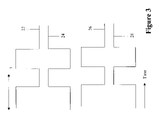
- FIG. 3 illustrates another exemplary timing diagram suitable for practicing an illustrative embodiment of the present invention.
- FIG. 4 illustrates two exemplary images suitable for producing a reduced-glare image, according to one embodiment of the present invention.
- FIG. 5 illustrates an exemplary reduced glare image of an object formed from two exemplary images illustrated in FIG. 4 .
- FIG. 6 is a flowchart illustrating steps for producing a reduced-glare image according to the teachings of the present invention.
- FIGS. 1–5 illustrate exemplary embodiments of a system and method suitable for recognizing an individual.
- FIGS. 1–5 illustrate exemplary embodiments of a system and method suitable for recognizing an individual.
- FIGS. 1–5 illustrate exemplary embodiments of a system and method suitable for recognizing an individual.
- FIGS. 1–5 illustrate exemplary embodiments of a system and method suitable for recognizing an individual.
- FIGS. 1–5 illustrate exemplary embodiments of a system and method suitable for recognizing an individual.
- the imaging system 4 for producing a reduced glare image suitable for use in identifying an object from the image is shown.
- the imaging system 4 includes a first light source 6 , a second light source 8 , an image acquisition device 10 , and a controller 12 .
- the imaging system 4 optionally includes a database 18 for holding images of other objects.
- the database 18 can be located at a location remote from the imaging system 4 . If the database 18 is located at a remote location, the imaging system 4 is capable of accessing the database 18 via a LAN, WAN, dedicated communication channel, or other communication medium such as a wireless medium or network.
- the controller 12 controls the actuation or triggering of the light sources 6 , 8 and the actuation or triggering of the image acquisition device 10 .
- the controller 12 optionally includes an image producer 13 for forming the reduced glare image of the object.
- the image producer 13 is included in the imaging system 4 as a module that operates in conjunction with the controller 12 , but not as a module within the controller 12 .
- the first and second light sources 6 and 8 help illuminate an object to be imaged.
- the image acquisition device 10 acquires a first image of the object illuminated with the first light source 6 and a second image of the object illuminated with the second light source 8 .
- the controller 12 actuates or triggers the image acquisition device 10 , the first light source 6 and the second light source 8 such that when the first image is acquired, the second light source 8 is not substantially illuminating the object.
- the controller 12 ensures that when the second image is acquired, the first light source 6 is not substantially illuminating the object.
- the image producer 13 uses the first image and the second image to form a reduced-glare image of the object, as explained in more detail below.
- the first light source 6 and the second light source 8 are separated by an angle 15 so that a glare caused by the first light source in the first image is located at a different location than a glare caused by the second light source in the second image.
- the light sources 6 , 8 used in the imaging system can be an AC operated light source with electronically driven luminance changeover, such as an illumination source operating with a color temperature at about 2856° K.
- fluorescent lighting can be used such as, a commercially available fluorescent light box.
- the image acquisition device 10 can include a CCD camera, or a video camera, or both, as well as other suitable acquisition devices known to those of ordinary skill in the art.
- Other suitable acquisition devices include, but are not limited to, high resolution solid-state (CCD) monochrome cameras.
- CCD solid-state
- One such CCD camera suitable for use in the imaging system 8 is the Sony® XC-77, available from Sony Electronics Inc. of 1 Sony Drive, Park Ridge, N.J. 07656.
- Other appropriate CCD cameras include the Sierra Scientific® MS-4030, the COHU Model 4815-5000, and the Dage® CCD-72.
- a timing diagram graphically illustrates the actuation of the light sources 6 and 8 , and the image acquisition device 10 , by the controller 12 .
- the light sources 6 and 8 are alternately actuated and synchronized with the image acquisition device 10 .
- Trace 14 represents an actuation signal produced by the controller 12 to turn the first light source 6 on and off at desired intervals.
- Trace 14 has a period ⁇ 1 .
- Trace 16 represents an actuation signal produced by the controller 12 to turn the second light source 8 on and off at desired intervals.
- Trace 16 has a period ⁇ 2 .
- Traces 14 and 16 are illustrated as representing actuation signals having two levels, nonetheless those skilled in the art will recognize that the actuation signals to actuate or trigger the light sources 6 and 8 can have more than two levels to indicate to each of the light sources a desired illumination intensity. In this manner, illumination intensity produced by one or both of the light sources 6 , 8 are variable and controllable by the controller 12 .
- Trace 18 represents an actuation signal produced by the controller 12 to actuate the image acquisition device 10 to acquire an image of a subject when the first light source 6 is in an on state.
- Trace 20 represents an actuation signal produced by the controller 12 to actuate the image acquisition device 10 to acquire another image of the subject with the second light source 8 is in an on state.
- Trace 22 represents an actuation signal produced by the controller 12 to turn the first light source 6 on and off at desired intervals.
- Trace 22 has a period ⁇ .
- Trace 24 represents an actuation signal produced by the controller 12 to turn the second light source 8 on and off at desired intervals.
- Trace 24 has a period ⁇ .
- Trace 26 represents an actuation signal produced by the controller 12 to actuate the image acquisition device 10 to acquire an image of a subject when the first light source 6 is in an on state.
- Trace 28 represents an actuation signal produced by the controller 12 to actuate the image acquisition device 10 to acquire another image of the subject with the second light source 8 is in an on state.
- the image acquisition device 10 acquires a first image of an object illuminated with the first light source 6 and a second image of the object illuminated with the second light source 8 . That is, when the first image is acquired, the second light source is not illuminating the object, and when the second image is acquired, the first light source is not illuminating the object.
- the time difference between the acquisition of the images should be sufficiently small to ensure the object does not move appreciably during imaging.
- a first image 32 and a second image 32 of a face acquired by the image acquisition device 10 is illustrated.
- the first image 32 was acquired by the image acquisition device 10 while the first light source 6 was in its on state and the second light source 8 was in its off state.
- the second image 34 of the face was acquired by the image acquisition device 10 while the second light source 8 was in its on state and the first light source 6 was in its off state.
- the first image 32 was acquired using illumination from the first light source 6 , but not the second light source 8
- the second image 34 was acquired using illumination from the second light source 8 , but not the first light source 6 .
- the first image 32 has a first glare spot 36 resulting from light from the first light source 6 reflecting off a portion, of eyeglasses worn by the individual.
- the second image 34 has a second glare spot 38 resulting from light from the second light source 8 reflecting off another portion of the same eyeglasses worn by the individual.
- the images 32 and 34 represent images acquired were the individual's head did not substantially move, nor did the individual's pose or facial expression substantially change between the acquiring of the first image 32 and the acquiring of the second image 34 .
- the image producer 13 uses the first image 32 and the second image 34 to form a reduced-glare image 42 in the following manner.
- the image producer 13 compares a luminous energy value of a first pixel 40 from a first location in the first image 32 and a luminous energy value of a second pixel 41 from a corresponding location in the second image 34 . From the comparison, the image producer 13 selects the pixel that has the lowest luminous energy value and uses that pixel to form the reduced-glare image 42 . For example, when the image producer 13 reaches a pixel location in the first image 32 corresponding to the first glare spot 36 , the image producer 13 chooses the corresponding pixel from the second image 34 for use in the reduced glare image 42 .
- the image producer 13 selects the corresponding pixel from the second image 34 since this pixel exhibits a lower luminous energy value than the pixel in the first image 36 .
- the image producer 13 repeats the comparison of luminous energy values between pixels at corresponding locations in the first image 32 and the second image 34 and forms the reduced glare image using the pixels determined to exhibit the smaller luminous energy value.
- the reduced glare image 42 of the object is a composite of the first image 32 and the second image 34 .
- step 44 the image acquisition device 10 acquires a first image of the object illuminated with the first light source 6 .
- step 46 the image acquisition device 10 acquires a second image of the object illuminated with the second light source 8 .
- the first light source 6 and the second light source 8 are separated by an angle. The angle is such so a glare caused by the first light source 6 in the first image is located at a first location in the first image and a glare caused by the second light source 8 in the second image is located in a second location.
- step 48 the image producer 13 performs a pixel comparison by comparing pixels from corresponding locations in the first image 32 and in the second image 34 .
- the comparison determines which of the corresponding pixels exhibit the lowest luminous value, and hence, the pixels that do not represent a glare component in the two images.
- step 50 the image producer 13 forms a composite or reduced glare image of the object using the pixels determined to exhibit the lower luminous intensity value.
- identification can proceed using several methods. For example, PCA, mentioned above, can be brought to bear to identify the individual. Other methods known to those of ordinary skill in the art suitable for identifying individuals using images may also be used.
Abstract
Description
Claims (21)
Priority Applications (1)
| Application Number | Priority Date | Filing Date | Title |
|---|---|---|---|
| US10/377,405 US7158099B1 (en) | 2003-02-27 | 2003-02-27 | Systems and methods for forming a reduced-glare image |
Applications Claiming Priority (1)
| Application Number | Priority Date | Filing Date | Title |
|---|---|---|---|
| US10/377,405 US7158099B1 (en) | 2003-02-27 | 2003-02-27 | Systems and methods for forming a reduced-glare image |
Publications (1)
| Publication Number | Publication Date |
|---|---|
| US7158099B1 true US7158099B1 (en) | 2007-01-02 |
Family
ID=37592312
Family Applications (1)
| Application Number | Title | Priority Date | Filing Date |
|---|---|---|---|
| US10/377,405 Expired - Lifetime US7158099B1 (en) | 2003-02-27 | 2003-02-27 | Systems and methods for forming a reduced-glare image |
Country Status (1)
| Country | Link |
|---|---|
| US (1) | US7158099B1 (en) |
Cited By (19)
| Publication number | Priority date | Publication date | Assignee | Title |
|---|---|---|---|---|
| US20050103753A1 (en) * | 2003-11-18 | 2005-05-19 | Matsushita Electric Industrial Co., Ltd. | Light processing apparatus |
| US20060087582A1 (en) * | 2004-10-27 | 2006-04-27 | Scharenbroch Gregory K | Illumination and imaging system and method |
| US20060222260A1 (en) * | 2005-03-30 | 2006-10-05 | Casio Computer Co., Ltd. | Image capture apparatus, image processing method for captured image, and recording medium |
| US20080048887A1 (en) * | 2006-08-24 | 2008-02-28 | Takata Corporation | Vehicle occupant detection system |
| US7346184B1 (en) | 2000-05-02 | 2008-03-18 | Digimarc Corporation | Processing methods combining multiple frames of image data |
| US20100141806A1 (en) * | 2007-03-15 | 2010-06-10 | Kansai University | Moving Object Noise Elimination Processing Device and Moving Object Noise Elimination Processing Program |
| US20140064574A1 (en) * | 2006-09-22 | 2014-03-06 | Eyelock. Inc. | Compact biometric acquisition system and method |
| CN104376545A (en) * | 2013-08-16 | 2015-02-25 | 联想(北京)有限公司 | Information processing method and electronic equipment |
| WO2015196916A1 (en) * | 2014-06-27 | 2015-12-30 | Beijing Zhigu Rui Tuo Tech Co., Ltd. | Imaging control methods and apparatuses |
| US20150379348A1 (en) * | 2014-06-25 | 2015-12-31 | Kodak Alaris Inc. | Adaptable eye artifact identification and correction system |
| CN106027824A (en) * | 2015-03-30 | 2016-10-12 | 富士施乐株式会社 | Image reading device and image forming apparatus |
| WO2016174084A1 (en) * | 2015-04-30 | 2016-11-03 | Carl Zeiss Microscopy Gmbh | Method for generating a reflection-reduced contrast image and corresponding devices |
| US9609230B1 (en) * | 2015-12-30 | 2017-03-28 | Google Inc. | Using a display as a light source |
| US9807269B2 (en) * | 2013-08-27 | 2017-10-31 | Xerox Corporation | System and method for low light document capture and binarization with multiple flash images |
| US10115033B2 (en) | 2013-07-30 | 2018-10-30 | Kodak Alaris Inc. | System and method for creating navigable views |
| US10382712B1 (en) | 2018-08-01 | 2019-08-13 | Qualcomm Incorporated | Automatic removal of lens flares from images |
| US10645358B2 (en) * | 2018-02-20 | 2020-05-05 | Gopro, Inc. | Saturation management for luminance gains in image processing |
| US10713520B2 (en) * | 2016-10-27 | 2020-07-14 | Engineering Innovation, Inc. | Method of taking a picture without glare |
| US20200311889A1 (en) * | 2019-03-28 | 2020-10-01 | Alibaba Group Holding Limited | Specular reflection reduction using polarized light sources |
Citations (5)
| Publication number | Priority date | Publication date | Assignee | Title |
|---|---|---|---|---|
| US6277067B1 (en) * | 1997-04-04 | 2001-08-21 | Kerry L. Blair | Method and portable colposcope useful in cervical cancer detection |
| JP2001273498A (en) * | 2000-03-24 | 2001-10-05 | Matsushita Electric Ind Co Ltd | Device, system, card and method for personal identification based on biometric |
| US6332693B1 (en) * | 1998-09-10 | 2001-12-25 | International Business Machines Corporation | Apparatus and method for intensifying illumination brightness by time-superposing multiple pulsed light sources |
| US6843566B2 (en) * | 2002-02-28 | 2005-01-18 | Kabushiki Kaisha Toshiba | Lighting device and projection type display apparatus using the same |
| US6862054B2 (en) * | 2002-03-06 | 2005-03-01 | Seiko Epson Corporation | Electro-optical device and electronic apparatus having a substrate that functions as a light guide plate |
-
2003
- 2003-02-27 US US10/377,405 patent/US7158099B1/en not_active Expired - Lifetime
Patent Citations (5)
| Publication number | Priority date | Publication date | Assignee | Title |
|---|---|---|---|---|
| US6277067B1 (en) * | 1997-04-04 | 2001-08-21 | Kerry L. Blair | Method and portable colposcope useful in cervical cancer detection |
| US6332693B1 (en) * | 1998-09-10 | 2001-12-25 | International Business Machines Corporation | Apparatus and method for intensifying illumination brightness by time-superposing multiple pulsed light sources |
| JP2001273498A (en) * | 2000-03-24 | 2001-10-05 | Matsushita Electric Ind Co Ltd | Device, system, card and method for personal identification based on biometric |
| US6843566B2 (en) * | 2002-02-28 | 2005-01-18 | Kabushiki Kaisha Toshiba | Lighting device and projection type display apparatus using the same |
| US6862054B2 (en) * | 2002-03-06 | 2005-03-01 | Seiko Epson Corporation | Electro-optical device and electronic apparatus having a substrate that functions as a light guide plate |
Cited By (38)
| Publication number | Priority date | Publication date | Assignee | Title |
|---|---|---|---|---|
| US7346184B1 (en) | 2000-05-02 | 2008-03-18 | Digimarc Corporation | Processing methods combining multiple frames of image data |
| US8126272B2 (en) | 2000-05-02 | 2012-02-28 | Digimarc Corporation | Methods combining multiple frames of image data |
| US20050103753A1 (en) * | 2003-11-18 | 2005-05-19 | Matsushita Electric Industrial Co., Ltd. | Light processing apparatus |
| US7532749B2 (en) * | 2003-11-18 | 2009-05-12 | Panasonic Corporation | Light processing apparatus |
| US7777778B2 (en) * | 2004-10-27 | 2010-08-17 | Delphi Technologies, Inc. | Illumination and imaging system and method |
| US20060087582A1 (en) * | 2004-10-27 | 2006-04-27 | Scharenbroch Gregory K | Illumination and imaging system and method |
| US20060222260A1 (en) * | 2005-03-30 | 2006-10-05 | Casio Computer Co., Ltd. | Image capture apparatus, image processing method for captured image, and recording medium |
| US7760962B2 (en) * | 2005-03-30 | 2010-07-20 | Casio Computer Co., Ltd. | Image capture apparatus which synthesizes a plurality of images obtained by shooting a subject from different directions, to produce an image in which the influence of glare from a light is reduced |
| US20080048887A1 (en) * | 2006-08-24 | 2008-02-28 | Takata Corporation | Vehicle occupant detection system |
| US20140064574A1 (en) * | 2006-09-22 | 2014-03-06 | Eyelock. Inc. | Compact biometric acquisition system and method |
| US20100141806A1 (en) * | 2007-03-15 | 2010-06-10 | Kansai University | Moving Object Noise Elimination Processing Device and Moving Object Noise Elimination Processing Program |
| US10558884B2 (en) | 2013-07-30 | 2020-02-11 | Kodak Alaris Inc. | System and method for creating navigable views |
| US10115033B2 (en) | 2013-07-30 | 2018-10-30 | Kodak Alaris Inc. | System and method for creating navigable views |
| CN104376545A (en) * | 2013-08-16 | 2015-02-25 | 联想(北京)有限公司 | Information processing method and electronic equipment |
| CN104376545B (en) * | 2013-08-16 | 2018-12-14 | 联想(北京)有限公司 | A kind of method and a kind of electronic equipment of information processing |
| US9807269B2 (en) * | 2013-08-27 | 2017-10-31 | Xerox Corporation | System and method for low light document capture and binarization with multiple flash images |
| US20150379348A1 (en) * | 2014-06-25 | 2015-12-31 | Kodak Alaris Inc. | Adaptable eye artifact identification and correction system |
| US9824271B2 (en) * | 2014-06-25 | 2017-11-21 | Kodak Alaris Inc. | Adaptable eye artifact identification and correction system |
| WO2015196916A1 (en) * | 2014-06-27 | 2015-12-30 | Beijing Zhigu Rui Tuo Tech Co., Ltd. | Imaging control methods and apparatuses |
| US10419687B2 (en) | 2014-06-27 | 2019-09-17 | Beijing Zhigu Rui Tuo Tech Co., Ltd | Imaging control methods and apparatuses |
| CN106027824A (en) * | 2015-03-30 | 2016-10-12 | 富士施乐株式会社 | Image reading device and image forming apparatus |
| CN106027824B (en) * | 2015-03-30 | 2019-04-09 | 富士施乐株式会社 | Image-reading device and image forming apparatus |
| US9560234B2 (en) * | 2015-03-30 | 2017-01-31 | Fuji Xerox Co., Ltd. | Image reading device and image forming apparatus |
| CN107592909A (en) * | 2015-04-30 | 2018-01-16 | 卡尔蔡司显微镜有限公司 | The method and its device of reflection contrast images are reduced for generating |
| WO2016174084A1 (en) * | 2015-04-30 | 2016-11-03 | Carl Zeiss Microscopy Gmbh | Method for generating a reflection-reduced contrast image and corresponding devices |
| CN107592909B (en) * | 2015-04-30 | 2020-01-17 | 卡尔蔡司显微镜有限公司 | Method for generating reduced reflectance contrast images and apparatus therefor |
| US10620417B2 (en) | 2015-04-30 | 2020-04-14 | Carl Zeiss Microscopy Gmbh | Method for generating a reflection-reduced contrast image and corresponding device |
| US10375314B1 (en) | 2015-12-30 | 2019-08-06 | Google Llc | Using a display as a light source |
| US10536647B2 (en) | 2015-12-30 | 2020-01-14 | Google Llc | Using a display as a light source |
| US9609230B1 (en) * | 2015-12-30 | 2017-03-28 | Google Inc. | Using a display as a light source |
| US10713520B2 (en) * | 2016-10-27 | 2020-07-14 | Engineering Innovation, Inc. | Method of taking a picture without glare |
| US11317070B2 (en) | 2018-02-20 | 2022-04-26 | Gopro, Inc. | Saturation management for luminance gains in image processing |
| US10645358B2 (en) * | 2018-02-20 | 2020-05-05 | Gopro, Inc. | Saturation management for luminance gains in image processing |
| US10382712B1 (en) | 2018-08-01 | 2019-08-13 | Qualcomm Incorporated | Automatic removal of lens flares from images |
| US10872402B2 (en) * | 2019-03-28 | 2020-12-22 | Advanced New Technologies Co., Ltd. | Specular reflection reduction using polarized light sources |
| US10878548B2 (en) * | 2019-03-28 | 2020-12-29 | Advanced New Technologies Co., Ltd. | Specular reflection reduction using polarized light sources |
| US11132777B2 (en) | 2019-03-28 | 2021-09-28 | Advanced New Technologies Co., Ltd. | Specular reflection reduction using polarized light sources |
| US20200311889A1 (en) * | 2019-03-28 | 2020-10-01 | Alibaba Group Holding Limited | Specular reflection reduction using polarized light sources |
Similar Documents
| Publication | Publication Date | Title |
|---|---|---|
| US7158099B1 (en) | Systems and methods for forming a reduced-glare image | |
| US20050111705A1 (en) | Passive stereo sensing for 3D facial shape biometrics | |
| US9792499B2 (en) | Methods for performing biometric recognition of a human eye and corroboration of same | |
| US7574021B2 (en) | Iris recognition for a secure facility | |
| US7801335B2 (en) | Apparatus and methods for detecting the presence of a human eye | |
| CN103383723B (en) | Method and system for spoof detection for biometric authentication | |
| Steiner et al. | Design of an active multispectral SWIR camera system for skin detection and face verification | |
| JP2003178306A (en) | Personal identification device and personal identification method | |
| US11714889B2 (en) | Method for authentication or identification of an individual | |
| CN108805024A (en) | Image processing method, device, computer readable storage medium and electronic equipment | |
| US20210256244A1 (en) | Method for authentication or identification of an individual | |
| JP6376474B2 (en) | Multi-view imaging system, acquired image composition processing method, and program | |
| JP7192872B2 (en) | Iris authentication device, iris authentication method, iris authentication program and recording medium | |
| JP5955031B2 (en) | Face image authentication device | |
| KR20030051970A (en) | Iris registration and recognition system | |
| CN106845449A (en) | A kind of image processing apparatus, method and face identification system | |
| CN109255282A (en) | A kind of biometric discrimination method, device and system | |
| JP5766096B2 (en) | Face image authentication device | |
| JP2004062846A (en) | Input device of personal identification device | |
| US20090324021A1 (en) | Method of Identification of a Person on the Iris of the Eye (Embodiments) | |
| CN113128254A (en) | Face capturing method, device, chip and computer readable storage medium | |
| US11341224B2 (en) | Handheld multi-sensor biometric imaging device and processing pipeline | |
| JPH10137219A (en) | Iris image processing device | |
| KR20040006703A (en) | Iris recognition system | |
| CN110443096A (en) | The application method of changeable filter camera for cloud platform identification |
Legal Events
| Date | Code | Title | Description |
|---|---|---|---|
| AS | Assignment |
Owner name: LAU ACQUISITION CORP., MASSACHUSETTS Free format text: SECURITY INTEREST;ASSIGNOR:VIISAGE TECHNOLOGY, INC.;REEL/FRAME:014162/0864 Effective date: 20030530 |
|
| AS | Assignment |
Owner name: COMMERCE BANK & TRUST COMPANY, MASSACHUSETTS Free format text: SECURITY INTEREST;ASSIGNOR:VISSAGE TECHNOLOGY, INC.;REEL/FRAME:014373/0913 Effective date: 20030602 |
|
| AS | Assignment |
Owner name: VIISAGE TECHNOLOGY, INC., MASSACHUSETTS Free format text: ASSIGNMENT OF ASSIGNORS INTEREST;ASSIGNORS:BERUBE, DENIS K.;CUSACK, JR, FRANCIS J.;EHN, DENNIS C.;REEL/FRAME:015149/0583;SIGNING DATES FROM 20031009 TO 20040204 |
|
| AS | Assignment |
Owner name: VISAGE TECHNOLOGY, INC., MASSACHUSETTS Free format text: RE-RECORD TO CORRECT THE 1ST CONVEYING PARTY'S NAME, PREVIOUSLY RECORDED AT REEL 015149, FRAME 0583.;ASSIGNORS:BERUBE, DENNIS K.;CUSACK, JR., FRANCIS J.;EHN, DENNIS C.;REEL/FRAME:015244/0397;SIGNING DATES FROM 20031009 TO 20040204 |
|
| AS | Assignment |
Owner name: L-1 IDENTITY SOLUTIONS, INC., CONNECTICUT Free format text: CHANGE OF NAME;ASSIGNOR:VIISAGE TECHNOLOGY, INC.;REEL/FRAME:018224/0028 Effective date: 20060829 |
|
| AS | Assignment |
Owner name: BANK OF AMERICA, N.A., ILLINOIS Free format text: SECURITY AGREEMENT;ASSIGNORS:L-1 IDENTITY SOLUTIONS, INC.;IMAGING AUTOMATION, INC.;TRANS DIGITAL TECHNOLOGIES CORPORATION;AND OTHERS;REEL/FRAME:018679/0105 Effective date: 20061019 |
|
| STCF | Information on status: patent grant |
Free format text: PATENTED CASE |
|
| AS | Assignment |
Owner name: L-1 IDENTITY SOLUTIONS OPERATING COMPANY, INC., CO Free format text: CHANGE OF NAME;ASSIGNOR:L-1 IDENTITY SOLUTIONS, INC.;REEL/FRAME:019309/0700 Effective date: 20070516 |
|
| AS | Assignment |
Owner name: BANK OF AMERICA, N.A., NORTH CAROLINA Free format text: SECURITY INTEREST;ASSIGNOR:L-1 IDENTITY SOLUTIONS OPERATING COMPANY;REEL/FRAME:021398/0145 Effective date: 20080805 |
|
| FPAY | Fee payment |
Year of fee payment: 4 |
|
| AS | Assignment |
Owner name: L-1 IDENTITY SOLUTIONS OPERATING COMPANY, CONNECTI Free format text: RELEASE BY SECURED PARTY;ASSIGNOR:BANK OF AMERICA, N.A., AS ADMINISTRATIVE AGENT;REEL/FRAME:026647/0453 Effective date: 20110725 |
|
| FEPP | Fee payment procedure |
Free format text: PAYOR NUMBER ASSIGNED (ORIGINAL EVENT CODE: ASPN); ENTITY STATUS OF PATENT OWNER: LARGE ENTITY Free format text: PAYER NUMBER DE-ASSIGNED (ORIGINAL EVENT CODE: RMPN); ENTITY STATUS OF PATENT OWNER: LARGE ENTITY |
|
| FEPP | Fee payment procedure |
Free format text: PAT HOLDER NO LONGER CLAIMS SMALL ENTITY STATUS, ENTITY STATUS SET TO UNDISCOUNTED (ORIGINAL EVENT CODE: STOL); ENTITY STATUS OF PATENT OWNER: LARGE ENTITY |
|
| REMI | Maintenance fee reminder mailed | ||
| FPAY | Fee payment |
Year of fee payment: 8 |
|
| SULP | Surcharge for late payment |
Year of fee payment: 7 |
|
| FEPP | Fee payment procedure |
Free format text: MAINTENANCE FEE REMINDER MAILED (ORIGINAL EVENT CODE: REM.) |
|
| FEPP | Fee payment procedure |
Free format text: 11.5 YR SURCHARGE- LATE PMT W/IN 6 MO, LARGE ENTITY (ORIGINAL EVENT CODE: M1556); ENTITY STATUS OF PATENT OWNER: LARGE ENTITY |
|
| MAFP | Maintenance fee payment |
Free format text: PAYMENT OF MAINTENANCE FEE, 12TH YEAR, LARGE ENTITY (ORIGINAL EVENT CODE: M1553); ENTITY STATUS OF PATENT OWNER: LARGE ENTITY Year of fee payment: 12 |