US7157724B2 - Detection lamp - Google Patents
Detection lamp Download PDFInfo
- Publication number
- US7157724B2 US7157724B2 US10/653,417 US65341703A US7157724B2 US 7157724 B2 US7157724 B2 US 7157724B2 US 65341703 A US65341703 A US 65341703A US 7157724 B2 US7157724 B2 US 7157724B2
- Authority
- US
- United States
- Prior art keywords
- light
- filter
- wavelength
- light source
- wavelengths
- Prior art date
- Legal status (The legal status is an assumption and is not a legal conclusion. Google has not performed a legal analysis and makes no representation as to the accuracy of the status listed.)
- Expired - Fee Related
Links
- 238000001514 detection method Methods 0.000 title claims description 20
- 230000005284 excitation Effects 0.000 claims abstract description 19
- 238000012360 testing method Methods 0.000 claims abstract description 5
- 239000000126 substance Substances 0.000 claims description 33
- 238000000034 method Methods 0.000 claims description 11
- 230000005540 biological transmission Effects 0.000 claims description 6
- 241000220317 Rosa Species 0.000 claims description 3
- 238000010998 test method Methods 0.000 claims 1
- 239000007850 fluorescent dye Substances 0.000 abstract description 5
- 239000000975 dye Substances 0.000 description 13
- 239000011521 glass Substances 0.000 description 10
- 229910052751 metal Inorganic materials 0.000 description 10
- 239000002184 metal Substances 0.000 description 10
- 239000004020 conductor Substances 0.000 description 8
- 239000000463 material Substances 0.000 description 8
- 239000004033 plastic Substances 0.000 description 8
- 238000000576 coating method Methods 0.000 description 5
- 238000010521 absorption reaction Methods 0.000 description 4
- 229910052782 aluminium Inorganic materials 0.000 description 4
- XAGFODPZIPBFFR-UHFFFAOYSA-N aluminium Chemical compound [Al] XAGFODPZIPBFFR-UHFFFAOYSA-N 0.000 description 4
- 239000012530 fluid Substances 0.000 description 4
- 230000003595 spectral effect Effects 0.000 description 4
- 230000006835 compression Effects 0.000 description 3
- 238000007906 compression Methods 0.000 description 3
- 238000005286 illumination Methods 0.000 description 3
- 238000009659 non-destructive testing Methods 0.000 description 3
- 229920000642 polymer Polymers 0.000 description 3
- 239000000243 solution Substances 0.000 description 3
- -1 thioxanthane Chemical compound 0.000 description 3
- 229910052724 xenon Inorganic materials 0.000 description 3
- GOLORTLGFDVFDW-UHFFFAOYSA-N 3-(1h-benzimidazol-2-yl)-7-(diethylamino)chromen-2-one Chemical compound C1=CC=C2NC(C3=CC4=CC=C(C=C4OC3=O)N(CC)CC)=NC2=C1 GOLORTLGFDVFDW-UHFFFAOYSA-N 0.000 description 2
- 239000000853 adhesive Substances 0.000 description 2
- 230000001070 adhesive effect Effects 0.000 description 2
- XJHABGPPCLHLLV-UHFFFAOYSA-N benzo[de]isoquinoline-1,3-dione Chemical compound C1=CC(C(=O)NC2=O)=C3C2=CC=CC3=C1 XJHABGPPCLHLLV-UHFFFAOYSA-N 0.000 description 2
- 238000010276 construction Methods 0.000 description 2
- 230000008021 deposition Effects 0.000 description 2
- GNBHRKFJIUUOQI-UHFFFAOYSA-N fluorescein Chemical compound O1C(=O)C2=CC=CC=C2C21C1=CC=C(O)C=C1OC1=CC(O)=CC=C21 GNBHRKFJIUUOQI-UHFFFAOYSA-N 0.000 description 2
- 229910052736 halogen Inorganic materials 0.000 description 2
- 150000002367 halogens Chemical class 0.000 description 2
- 238000010438 heat treatment Methods 0.000 description 2
- 125000002080 perylenyl group Chemical group C1(=CC=C2C=CC=C3C4=CC=CC5=CC=CC(C1=C23)=C45)* 0.000 description 2
- CSHWQDPOILHKBI-UHFFFAOYSA-N peryrene Natural products C1=CC(C2=CC=CC=3C2=C2C=CC=3)=C3C2=CC=CC3=C1 CSHWQDPOILHKBI-UHFFFAOYSA-N 0.000 description 2
- 229920001568 phenolic resin Polymers 0.000 description 2
- 239000010453 quartz Substances 0.000 description 2
- 230000005855 radiation Effects 0.000 description 2
- 238000002310 reflectometry Methods 0.000 description 2
- 239000000523 sample Substances 0.000 description 2
- VYPSYNLAJGMNEJ-UHFFFAOYSA-N silicon dioxide Inorganic materials O=[Si]=O VYPSYNLAJGMNEJ-UHFFFAOYSA-N 0.000 description 2
- KXGFMDJXCMQABM-UHFFFAOYSA-N 2-methoxy-6-methylphenol Chemical compound [CH]OC1=CC=CC([CH])=C1O KXGFMDJXCMQABM-UHFFFAOYSA-N 0.000 description 1
- 239000004593 Epoxy Substances 0.000 description 1
- GYHNNYVSQQEPJS-UHFFFAOYSA-N Gallium Chemical compound [Ga] GYHNNYVSQQEPJS-UHFFFAOYSA-N 0.000 description 1
- WHXSMMKQMYFTQS-UHFFFAOYSA-N Lithium Chemical compound [Li] WHXSMMKQMYFTQS-UHFFFAOYSA-N 0.000 description 1
- HBBGRARXTFLTSG-UHFFFAOYSA-N Lithium ion Chemical compound [Li+] HBBGRARXTFLTSG-UHFFFAOYSA-N 0.000 description 1
- 238000004378 air conditioning Methods 0.000 description 1
- 230000000712 assembly Effects 0.000 description 1
- 238000000429 assembly Methods 0.000 description 1
- 239000000919 ceramic Substances 0.000 description 1
- 239000011248 coating agent Substances 0.000 description 1
- 239000002826 coolant Substances 0.000 description 1
- 238000001816 cooling Methods 0.000 description 1
- 230000023077 detection of light stimulus Effects 0.000 description 1
- 230000000694 effects Effects 0.000 description 1
- 238000001917 fluorescence detection Methods 0.000 description 1
- 238000002795 fluorescence method Methods 0.000 description 1
- 239000000446 fuel Substances 0.000 description 1
- 229910052733 gallium Inorganic materials 0.000 description 1
- 239000007789 gas Substances 0.000 description 1
- 210000004209 hair Anatomy 0.000 description 1
- 238000001746 injection moulding Methods 0.000 description 1
- 229910052744 lithium Inorganic materials 0.000 description 1
- 229910001416 lithium ion Inorganic materials 0.000 description 1
- 239000000314 lubricant Substances 0.000 description 1
- 229910052987 metal hydride Inorganic materials 0.000 description 1
- 238000012986 modification Methods 0.000 description 1
- 230000004048 modification Effects 0.000 description 1
- 239000010705 motor oil Substances 0.000 description 1
- 238000000465 moulding Methods 0.000 description 1
- 229910052759 nickel Inorganic materials 0.000 description 1
- PXHVJJICTQNCMI-UHFFFAOYSA-N nickel Substances [Ni] PXHVJJICTQNCMI-UHFFFAOYSA-N 0.000 description 1
- 230000003287 optical effect Effects 0.000 description 1
- 239000005011 phenolic resin Substances 0.000 description 1
- 238000007747 plating Methods 0.000 description 1
- 239000003507 refrigerant Substances 0.000 description 1
- 230000035939 shock Effects 0.000 description 1
- 229910052710 silicon Inorganic materials 0.000 description 1
- 239000010703 silicon Substances 0.000 description 1
- 238000001228 spectrum Methods 0.000 description 1
- 238000012421 spiking Methods 0.000 description 1
- 238000007740 vapor deposition Methods 0.000 description 1
- FHNFHKCVQCLJFQ-UHFFFAOYSA-N xenon atom Chemical compound [Xe] FHNFHKCVQCLJFQ-UHFFFAOYSA-N 0.000 description 1
Images


Classifications
-
- F—MECHANICAL ENGINEERING; LIGHTING; HEATING; WEAPONS; BLASTING
- F21—LIGHTING
- F21V—FUNCTIONAL FEATURES OR DETAILS OF LIGHTING DEVICES OR SYSTEMS THEREOF; STRUCTURAL COMBINATIONS OF LIGHTING DEVICES WITH OTHER ARTICLES, NOT OTHERWISE PROVIDED FOR
- F21V15/00—Protecting lighting devices from damage
- F21V15/01—Housings, e.g. material or assembling of housing parts
-
- F—MECHANICAL ENGINEERING; LIGHTING; HEATING; WEAPONS; BLASTING
- F21—LIGHTING
- F21V—FUNCTIONAL FEATURES OR DETAILS OF LIGHTING DEVICES OR SYSTEMS THEREOF; STRUCTURAL COMBINATIONS OF LIGHTING DEVICES WITH OTHER ARTICLES, NOT OTHERWISE PROVIDED FOR
- F21V15/00—Protecting lighting devices from damage
- F21V15/04—Resilient mountings, e.g. shock absorbers
-
- F—MECHANICAL ENGINEERING; LIGHTING; HEATING; WEAPONS; BLASTING
- F21—LIGHTING
- F21V—FUNCTIONAL FEATURES OR DETAILS OF LIGHTING DEVICES OR SYSTEMS THEREOF; STRUCTURAL COMBINATIONS OF LIGHTING DEVICES WITH OTHER ARTICLES, NOT OTHERWISE PROVIDED FOR
- F21V29/00—Protecting lighting devices from thermal damage; Cooling or heating arrangements specially adapted for lighting devices or systems
- F21V29/15—Thermal insulation
-
- G—PHYSICS
- G01—MEASURING; TESTING
- G01J—MEASUREMENT OF INTENSITY, VELOCITY, SPECTRAL CONTENT, POLARISATION, PHASE OR PULSE CHARACTERISTICS OF INFRARED, VISIBLE OR ULTRAVIOLET LIGHT; COLORIMETRY; RADIATION PYROMETRY
- G01J1/00—Photometry, e.g. photographic exposure meter
- G01J1/02—Details
- G01J1/08—Arrangements of light sources specially adapted for photometry standard sources, also using luminescent or radioactive material
-
- G—PHYSICS
- G01—MEASURING; TESTING
- G01M—TESTING STATIC OR DYNAMIC BALANCE OF MACHINES OR STRUCTURES; TESTING OF STRUCTURES OR APPARATUS, NOT OTHERWISE PROVIDED FOR
- G01M3/00—Investigating fluid-tightness of structures
- G01M3/02—Investigating fluid-tightness of structures by using fluid or vacuum
- G01M3/04—Investigating fluid-tightness of structures by using fluid or vacuum by detecting the presence of fluid at the leakage point
- G01M3/20—Investigating fluid-tightness of structures by using fluid or vacuum by detecting the presence of fluid at the leakage point using special tracer materials, e.g. dye, fluorescent material, radioactive material
- G01M3/22—Investigating fluid-tightness of structures by using fluid or vacuum by detecting the presence of fluid at the leakage point using special tracer materials, e.g. dye, fluorescent material, radioactive material for pipes, cables or tubes; for pipe joints or seals; for valves; for welds; for containers, e.g. radiators
- G01M3/226—Investigating fluid-tightness of structures by using fluid or vacuum by detecting the presence of fluid at the leakage point using special tracer materials, e.g. dye, fluorescent material, radioactive material for pipes, cables or tubes; for pipe joints or seals; for valves; for welds; for containers, e.g. radiators for containers, e.g. radiators
- G01M3/228—Investigating fluid-tightness of structures by using fluid or vacuum by detecting the presence of fluid at the leakage point using special tracer materials, e.g. dye, fluorescent material, radioactive material for pipes, cables or tubes; for pipe joints or seals; for valves; for welds; for containers, e.g. radiators for containers, e.g. radiators for radiators
-
- G—PHYSICS
- G01—MEASURING; TESTING
- G01M—TESTING STATIC OR DYNAMIC BALANCE OF MACHINES OR STRUCTURES; TESTING OF STRUCTURES OR APPARATUS, NOT OTHERWISE PROVIDED FOR
- G01M3/00—Investigating fluid-tightness of structures
- G01M3/38—Investigating fluid-tightness of structures by using light
Definitions
- the invention relates to a light source and system for detecting leaks in fluid systems using light-emitting substances.
- Leak detection methods have been developed to analyze fluid systems (e.g., climate control systems such as heating, cooling, ventilating, and air conditioning systems, hydraulics, engine oil systems, automatic transmission systems, fuel systems, brake systems, or radiator coolant systems) using dyes.
- Some methods operate by adding emissive substances (e.g., fluorescent dyes) to the refrigerants and/or lubricants of the fluid system.
- emissive substances e.g., fluorescent dyes
- Suitable dyes include naphthalimide, perylene, thioxanthane, coumarin, or fluorescein, and derivatives thereof.
- Leaks can be detected by observing fluorescence of the dye at leak sites resulting from excitation of the dye with a light source having particular illumination characteristics (e.g., wavelength, intensity, or beam spread).
- Fluorescence is the emission of light at wavelengths greater than the wavelength of light emitted from the light source used to probe for leaks.
- Suitable light sources for use in fluorescence detection emit light of wavelengths suitable to excite the dye and cause light emission.
- the visibility of the fluorescence from the dye can be increased when the leaks are illuminated with light having a wavelength between 300 and 700 nanometers.
- the dyes fluoresce brightly when excited by light sources which emit light in the 300 to 500 nanometer range.
- Typical light sources used in these types of applications include alternating current lamps operating on either 110 to 220 volts, such as the PAR 38, manufactured by Phillips. These lamps had power outputs in the 100 to 200 watt range and produced a substantial amount of light outside of the wavelength range desired to produce a good fluorescence signal. These lamps also created a large amount of heat and required the use of a ballast which provided additional bulk and weight. Self-ballasted lamps were also developed that had relatively long warm-up periods and were very sensitive to voltage surges.
- the invention features a light source that is small, portable, and light weight.
- the light source produces a narrow emission beam of light.
- the light source produces light having a wavelength that can effectively excite emissive substances used in leak detection systems.
- the light source can have a low-voltage lamp or a low heat generating lamp, such as a light emitting diode (LED).
- LED light emitting diode
- the invention features a light source for examination of a substance which emits light at a wavelength greater than a wavelength of light emitted from the light source when the substance is excited by the wavelength of light emitted from the light source.
- the light source includes a housing having a light outlet, a reflector located within the housing, a lamp positioned in the housing between the reflector and light outlet, and a filter positioned in the housing between the lamp and the light outlet. Accordingly, the wavelength of the light emitted from the light source through the light outlet is restricted to a predetermined range effective to enhance the detection of emission of light from a substance when the substance is excited by the wavelength of light emitted from the light source.
- the preferred lamp is a low-voltage lamp (e.g., a halogen lamp).
- the preferred reflector is a parabolic reflector.
- the invention features a light source for examination of a substance which emits light at a wavelength greater than a wavelength of light emitted from the light source when the substance is excited by the wavelength of light emitted from the light source.
- the light source includes a housing having a light outlet, and a low-voltage lamp positioned in the housing and oriented to emit light through the light outlet.
- the lamp is capable of being connected to a source of electrical power.
- the low-voltage lamp emits light of a wavelength within a predetermined range effective to enhance the detection of emission of light from a substance when the substance is excited by the wavelength of light emitted from the lamp.
- the low-voltage lamp can be a low heat generating lamp.
- the low-voltage lamp can be a light emitting diode.
- the invention features a light source including a housing having a light outlet, and a low heat generating lamp positioned in the housing and oriented to emit light through the light outlet.
- a filter can restrict the wavelengths of light emitted from the lamp and the light reflected by the reflector.
- a filter can employ an absorption filter, dichroic filter, or other interference filter.
- the filter can be part of the glass that surrounds the element of the lamp.
- the lamp is capable of being connected to a source of electrical power, such as a battery, battery pack, or transformer.
- the reflector can be a dichroic reflector.
- the reflector can have a faceted surface or a smooth surface.
- the reflector can substantially reflect a selected wavelength of the light emitted from the lamp. For example, the reflector can reflect light primarily in the blue wavelength range, in the ultraviolet wavelength range, or in the blue and ultraviolet wavelength ranges.
- the invention features a system for detecting leaks in fluid systems.
- the system includes a substance capable of emitting an emission wavelength of light after being excited by an excitation wavelength of light, and the light source, which is capable of emitting the excitation wavelength of light.
- the substance can be an emissive leak detection dye, such as a naphthalimide, perylene, thioxanthane, coumarin, or fluorescein.
- an emissive leak detection dye such as a naphthalimide, perylene, thioxanthane, coumarin, or fluorescein.
- the system can include a filter lens for detecting the emission wavelength of light, where the emission wavelength of light emitted is enhanced by the utilization of filter lens by an observer of the emission wavelength.
- the filter lens can be incorporated in eyewear or a shield.
- the shield can be hand-held or mounted directly on the light source. When mounted on the light source, the observer can view the emission wavelength through the mounted filter lens.
- the low-voltage lamp can be a high color temperature, low voltage bulb, such as, for example, a quartz halogen-xenon bulb.
- Small, direct current lamps of the halogen type, or similar lamps rich in gases such as xenon require no ballast, are small in dimension, are light weight, and are typically not subject to voltage surges or spiking.
- the low-voltage lamps provide portability.
- the low-voltage lamp can be an LED or an array of LEDs.
- the low-voltage lamps can be powered by batteries (e.g., 4.5V, 6V, 9V, or 12V batteries) or battery packs.
- the batteries or battery packs can be rechargeable.
- the low-voltage lamp can be powered by a transformer.
- Reflectors can be used to adjust the output wavelengths of light from the low-voltage lamp so that sufficient light power density (i.e., candle power density) reaches the emissive substance.
- the light source can include a reflector.
- the reflector can be a focusing reflector or a parabolic reflector.
- the parabolic shape of the reflector geometry can create a collimated beam consisting of parallel beams of light.
- the collimated beam can provide a relatively constant illumination intensity over the leak detection area.
- the parabolic reflector has a three-dimensional paraboloid shape.
- a lengthwise cross-section of a parabolic reflector reveals a parabolic shape having a focal point.
- light rays emanating from the focal point are reflected by the surface of the paraboloid in a direction parallel to the lengthwise axis of the reflector to form the collimated beam. Because the rays are parallel, they do not noticeably diverge or converge with distance.
- the energy density of the light is relatively constant at short (e.g., 1 foot), medium (e.g., 3–5 feet) and long distances (e.g., up to about 100 feet) from the lamp.
- Z is the lengthwise axis
- X and Y are the perpendicular cartesian axes
- R represents the focal point.
- the focal point can be between about 0.005 inches and about 2.00 inches, preferably between about 0.01 inches and about 1.50 inches.
- the lengthwise axis can be between about 0.3 inches and about 8 inches, preferably between about 0.5 inches and 6 inches.
- the corresponding diameter of the paraboloid is between about 0.50 inches and about 8 inches, preferably between about 0.75 inches and about 3 inches.
- the lamp is located at or near the focal point.
- the reflector can have faceted or smooth surfaces to further modify light distribution.
- the faceted arrangement can improve the distribution of the light, or can smooth or break up light-dark edges. Facets on the surfaces of the reflector can range from fine, scarcely visible grains to clearly visible faceting, with the effect being correspondingly less or more pronounced.
- the reflectors can be metal (e.g., aluminum), glass, or plastic.
- the glass or plastic reflectors can be coated (e.g., with a metal) to obtain the particular reflective properties. The coatings can be applied, for example, by vapor deposition or plating.
- Detection of fluorescence can be enhanced when the wavelength of the light emitted from the light source is restricted so that little or no light of the emission wavelength comes from the light source (e.g., little or no light beyond the excitation wavelength, extending into the visible region).
- the wavelength of the light emitted from the light source can be controlled by use of reflectors with faceted surfaces or dichroic coatings.
- the wavelength can be further influenced by passing the light through a filter before it exits the light source.
- Dichroic coatings produce their reflection properties through the phenomenon of interference.
- the dichroic coatings consist of multiple (e.g., up to several dozen) thin layers, each only a quarter of a wavelength of the light thick, alternating between materials of a high and low refractive index. Fine tuning of the thicknesses of the layers and the way they are combined enable virtually any reflection curve to be created.
- the maximum reflectivity is nearly 100%, and there is virtually no absorption of radiation in the regions of low reflectivity. Accordingly, dichroic reflectors are substantially loss-free; the light that is not reflected is passed through the reflector or absorbed by the reflector.
- the cold-light reflectors which reflect visible light between about 300 and 750 nanometers and allow radiated heat to pass unhindered through the glass. This arrangement greatly reduces thermal load on the illuminated surface or object.
- the reflectors can reflect the blue wavelength range and/or the ultraviolet wavelength range. In the case of the blue-light reflector, only the blue wavelength range of the spectrum (e.g., between 400 and 500 nanometers) is reflected. In the case of the ultraviolet reflector, only the ultraviolet wavelength range (e.g., between about 300 and 400 nanometers) emitted by the lamp is reflected.
- Cold-light reflectors can excite emissive substances well since many emissive substances are excited by light in the wavelength range that is reflected by cold-light reflectors (i.e., 300 to 500 nanometers). Some white-light reflectors can excite emissive substances well since many emissive substances can be excited by light in the wavelength range that is reflected by the white-light reflectors (i.e, 400 to 700 nanometers). Light produced above these ranges is largely wasted since it may not produce the desired emission, produces additional heat, and can detract from the ability of an observer to see the emission wavelength. Thus, dichroic reflectors and faceted reflectors, which have narrow bandwidths of reflected light output can be used to provide proper excitation wavelengths for emissive substances and provide a precision not possible using other types of reflectors.
- Lamps can also be effective at providing the wavelength range required to observe emission by providing strong intensities of light.
- the narrower the beam spread the greater the light power density (e.g., candle power per unit area; mW/cm 2 ) and the greater the intensity of created emission.
- Filters can be an integral part of the reflector unit or can be independent of the reflector lamp but used in conjunction with it.
- An LED light source can have a narrow spectral output that does not need to employ a filter.
- Optical filters can also be used for safety purposes. Suitable filters include absorption filters, dichroic filters, or interference filters. The dichroic filters operate on the principal of interference. These filters were designed to transmit the wavelength of light which can excite the emissive substance, for example, at the site of a leak (i.e., light in the blue wavelength range or ultraviolet wavelength range).
- Suitable light sources can be identified by testing the average light power density of the light in the desired spectral region for excitation at fixed distances from the light outlet (e.g., at one foot, three foot, and five foot distances).
- the average light power density is measured using a detector that detects light in the excitation region (e.g., a 320–400 nm detector or a 400–500 nm detector).
- the detector can be a radiometer such as M007-004 or a blue hazard probe such as M007-027, available from UV Process Supply, Inc.
- a suitable light sources has an average light power density in the ultraviolet wavelength region of at least 0.1 mW/cm 2 (e.g., between 0.2 mW/cm 2 and 1 mW/cm 2 ) or in the blue wavelength region of at least 0.75 mW/cm 2 (e.g., between 1 mW/cm 2 and 50 mW/cm 2 , preferably between 5 mW/cm 2 and 20 mW/cm 2 ) at a distance of two feet or more (e.g., three feet or five feet) from the light outlet.
- the filter lens can be part of a shield or eyewear used by the user of a fluorescence leak detection system.
- the filter lens permits only light of certain wavelengths (e.g., the emission wavelength, but not the excitation wavelength) to pass and to be detected by the user.
- the filter lens can take several forms, including eyewear (e.g., glasses, or goggles), or shields (e.g., face shields).
- the filter lens can be designed to reduce or eliminate exposure of the observer to damaging ultraviolet radiation.
- the filter lens when used in combination with filters, can lead to enhanced detection of fluorescence.
- FIG. 1 is a drawing depicting a sectional view of one embodiment of a light source having parabolic reflector for examining substances which emit light at a wavelength greater than the wavelength of light emitted from the light source which excites the substance.
- FIG. 2 is a drawing depicting an exploded view of one embodiment of a light source having a parabolic reflector.
- FIG. 3 is a drawing depicting a perspective view of eyewear including long wavelength pass material for use in conjunction with a light source.
- FIG. 4 is a drawing depicting a perspective view of a face shield including long wavelength pass material for use in conjunction with a light source.
- FIG. 5 is a drawing depicting a sectional view of a light source having parabolic reflector and a battery pack.
- FIG. 6 is a drawing depicting an exploded view of an alternative embodiment of a light source having a parabolic reflector.
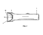
- FIG. 17 is a drawing depicting a sectional view of one embodiment of a light source having a low-voltage light source.
- one embodiment of the light source consists of housing 1 , which can be constructed of phenolic resin, plastic, or other suitable material.
- the unit is cylindrical in construction and hollow and has affixed at either end thereto front cap 2 and rear cap 3 . Both caps can be constructed of aluminum or other suitable materials.
- Front cap 2 includes light outlet 25 which allows light to exit from the light source.
- Front cap 2 has positioned directly behind it filter 4 , such as, for example, a BSI lens filter, No. PS-600.
- This particular filter provides maximum transmission of light at a wavelength of approximately 400 nanometers, wherein about 82% of the light at that wavelength is transmitted through the filter lens.
- the filter can be made of glass.
- the filter generally transmits light in a wavelength range shorter that the emission wavelength of the emissive substance.
- the filter has a flat or a lens shape.
- compression spring 5 Located directly behind the filter 4 is compression spring 5 which aides in positioning the filter and reflector 6 in proper spatial relationship within the housing and further provides some shock-absorbing assistance.
- Reflector 6 is a parabolic reflector.
- Reflector 6 located behind filter 4 and separated by compression spring 5 , is a molded glass reflector, metal plated plastic reflector, or a polished metal reflector.
- the reflector can be a dichroic reflector or have a faceted surface. In certain embodiments, the reflector can be faceted and have a dichroic coating on its surface.
- the reflector can be a cold-light reflector.
- the parabolic reflector can be machined from metal (e.g., aluminum) or molded from glass or plastic. The surface of the reflector is polished. Suitable metal reflectors can be prepared from spun metal created off a parabolic mandrel. Alternatively, metal reflectors can be machined from an aluminum block.
- Suitable plastic reflectors can be prepared by injection molding a plastic piece in a paraboloid form followed by deposition of metal onto the plastic to form a reflective surface.
- a glass reflector can be prepared by molding.
- a dichroic surface can be formed on the glass surface by sequential deposition of the interference layers.
- the reflector has a reflective front surface 9 .
- the surface can be configured to reflect visible light from the reflector.
- the surface can transmit heat through the reflector.
- the front surface 9 can be provided with facets 7 A, while providing a uniform beam of illumination from lamp 10 .
- front surface 9 can be smooth.
- Lamp 10 and reflector 6 are chosen to provide a collimated beam. Extending from back surface 8 of reflector 6 is mounting portion 14 . Lamp 10 is mounted in mounting portion 14 with the filament portion 10 A extending beyond the front surface 9 of reflector 6 . Lamp 10 has a filament portion 10 A and a neck portion 10 B. Included therein is filament 11 , which is connected at its rear to terminal 12 and terminal 13 (not shown). (Terminal 13 is not visible in the view because it is parallel to terminal 12 .)
- Lamp 10 is aligned in the parabolic reflector to maximize the collimated nature of the light beam, so that a tightly collimated beam with a high light density can be produced.
- the position of the lamp in the reflector is adjusted so that the light from the lamp emanates from the area nearest the focal point of the paraboloid.
- a target consisting of concentric circles with cross hairs along the X and Y axes of the circles
- the lamp is inserted into the reflector and the power is turned on so that the light strikes the target.
- the size of the beam on the target is noted.
- the position of the lamp in the reflector is incrementally adjusted until the size of the beam on the target is minimized. This position indicates the highest degree of collimation and optimum alignment.
- Socket 15 receives terminals 12 and 13 provides connections to circuit conductors 16 and 17 .
- Socket 15 is constructed of ceramic or similar material.
- Conductor portion 16 A extends to on/off switch 18 and continues through conductor portion 16 B to internal battery 28 or external battery pack 28 A.
- the other conductor 17 extends directly from socket 15 to battery 28 or battery pack 28 A.
- the lamp typically operates from a source having a voltage of 12V or less.
- the low-voltage lamp is a 4.5V, 6V, or 12V lamp.
- the lamp can draw, for example, approximately 20 watts of power using a 6V power source.
- the low-voltage lamp can be a high color temperature, low voltage bulb, such as, for example, a quartz halogen-xenon bulb.
- a high color temperature is a color temperature greater than 2600° K, preferably greater than 2900° K, more preferably greater than 3000° K, and most preferably greater than 3100° K.
- Suitable low-voltage lamps include, for example, 12V lamps XENOPHOT HLX 64610 (Sylvania) or PR-120 (JKL), 6V lamps XENOPHOT HLX 64250 (Sylvania), PSI-X631-LP (PSI) or PR-140 (JKL), and 4.5V lamps PSI-X4531-ELP (PSI) or PR-90 (JKL).
- Lamp 10 can be bonded to mounting portion 14 by means of a suitable adhesive, such as a silicon or epoxy based adhesive.
- a suitable adhesive such as a silicon or epoxy based adhesive.
- Assemblies having both the lamp and reflector include 50MR160Q12NSP (12V, Sylvania), FRB 35MR16Q/8/NSP (Sylvania), 419905P AR-70 (Osram), PSI-RP30 (parabolic reflector, PSI), and PSI-RP20 (parabolic reflector, PSI).
- the power source can consist of a battery 28 , set of batteries, or battery pack 28 A.
- the battery or battery pack can be disposable or rechargeable batteries.
- the power source can be a transformer that steps a 110V or 220V source down to a low-voltage suitable to power the low-voltage lamp.
- Switch 18 is utilized to turn the light source on or off during usage of the present novel light source to permit detection of the substances which emit light at wavelengths greater than the wavelength of the light emitted from the light source used to excite the substance.
- Heat shield 19 extends around the rear portion of reflector 6 , mounting portion 14 , and socket 15 , and is held in place against the rear of reflector 6 by means of portions of rear cap 3 .
- the heat shield assists in transmitting excess heat through the back surface 8 and neck portion 14 of reflector 6 , which render the lamp assembly comfortable to the touch during operation.
- the filter lens can be a long wavelength pass material which reduces the amount of short wavelength light (e.g., the excitation wavelength) observed by the user or detector.
- filter lens 31 or 41 restricts the detection of wavelengths of light emitted from the light source.
- the filter lens permits only light of certain wavelengths (e.g., the emission wavelength) to pass and to be detected by the user.
- the filter lens can be housed in a shield 40 or eyewear 30 . In embodiments, the filter lens allows wavelengths greater than the excitation wavelength to be observed.
- the filter lens can include a trim filter in addition to the primary filter, which can reduce or eliminate noise that can lead to false negative test results (i.e., failing to detect a problem when the problem exists) when observing a fluorescence in non-destructive testing.
- the trim filter can block transmission of wavelengths that compete with detection of the emission wavelength from the dye.
- the trim filter can block a set of wavelengths different from the wavelengths blocked by the primary filter.
- the inclusion of a trim filter can facilitate use of a light source that emits light having a wavelength longer than the excitation wavelength. By permitting the light source to emit light having a broader emission range, the heat produced by the light source can be reduced and the cost of any filter associated with the light source can be reduced.
- a light source can illuminate the test area with light of wavelengths up to 700 nm, when the filter lens includes a primary filter that blocks light in the range of 720 to 850 nm and a trim filter that blocks light from 650 to 850 nm.
- the primary filter can include a rose colored dye and the trim filter can include a blue colored dye.
- the dyes can be Polymer Solutions 755 and Polymer Solutions 694, available from Polymer Solutions, Incorporated, Blacksburg, Va.
- FIG. 6 another embodiment of the light source consists of housing 1 , is cylindrical in construction and has front lip 2 A and rear cap 3 .
- Front lip 2 A includes light outlet 25 which allows light to exit from the light source.
- Housing 1 has vents 60 that allow heat to escape from the light source.
- Filter 4 is positioned directly behind front lip 2 A.
- O-ring 5 A and compression spring 5 are positioned behind filter 4 to which aides in positioning filter 4 and reflector 6 in proper spatial relationship within the housing and can provide cushioning.
- Reflector 6 is a parabolic reflector, located behind filter lens 4 .
- the reflector has a reflective front surface 9 and can be provided with facets 7 A.
- Lamp 10 is located within the reflector.
- Heat shield 19 extends around the rear portion of reflector 6 , mounting portion 14 , and socket 15 , and is held in place against the rear of reflector 6 by means of portions of rear cap 3 .
- Lamp 10 and reflector 6 are chosen to provide a collimated beam.
- Lamp 10 is connected to socket 15 , which provides connections to circuit conductors 16 A and 17 .
- Conductor portion 16 A extends to switch 18 and continues through conductor portion 16 B to a power source.
- conductors 16 B and 17 can be connected to clip 50 that can be attached to a transformer or battery.
- the low-voltage lamp can be a light emitting diode (LED).
- the LED can emit wavelengths of light predominantly in the ultraviolet, violet, blue or green spectral range.
- the range of wavelengths emitted from the LED is narrow, typically less than 40 nm, preferably less than 35 nm.
- These LEDs can be used in a lamp without the need to use a filter lens because of the narrow wavelength range of the light emission.
- a white light LED can be used, in combination with a lens filter, such as an absorption filter or a dichroic filter.
- the LED can be powered by batteries, such as alkaline batteries, lithium batteries, or metal air batteries, or rechargeable batteries, such as lithium ion batteries or nickel metal hydride batteries.
- the LED can have a longer lifespan than an incandescent bulb.
- the battery used to power the LED can also last longer due to the low power consumption.
- the LED can have improved shock and vibration stability in comparison to an incandescent bulb.
- a single LED can be used in the light source.
- an array of LEDs for example, 3–20 LEDs, preferably 4–16 LEDs, can be used in the light source.
- the LED can be a diffused-type, which spreads light to a viewing angle of +/ ⁇ 35° from center or a non-diffused type, which produce light in a narrow viewing angle of less than +/ ⁇ 15° from center.
- the LED can be a gallium-based LED, such as, for example, a GaN, GaP:N, or other doped GaP LED. Suitable LEDs are commercially available, for example, from American Opto Plus LED, Inc. (San Dimas, Calif.), or Kwality Electronics Industries.
- Low heat generating lamps can improve safety when detecting leaks. Low heat generating lamps do not produce heat that can burn a user of the light source or cause materials in the vicinity of the leak detection to ignite.
- the low heat generating light source can be an LED described above. The narrow range of wavelengths emitted from the LED can reduce infrared emissions. In addition, the low voltage required to produce light from the low-voltage light source can reduce resistive heating.
- the light source includes housing 1 , which contains low-voltage lamp 10 or low heat generating lamp 10 .
- Low-voltage lamp 10 can be an LED, or an array of LEDs.
- Housing 1 can contain reflector 6 , which can direct light emitted from lamp 10 out of light outlet 25 . Light passing through outlet 25 can pass through filter 4 .
Abstract
Description
-
- The paraboloid can be described by the formula
Z=(X 2 +Y 2)/2R
- The paraboloid can be described by the formula
Claims (19)
Priority Applications (1)
| Application Number | Priority Date | Filing Date | Title |
|---|---|---|---|
| US10/653,417 US7157724B2 (en) | 1996-02-08 | 2003-09-03 | Detection lamp |
Applications Claiming Priority (6)
| Application Number | Priority Date | Filing Date | Title |
|---|---|---|---|
| US08/598,435 US5674000A (en) | 1996-02-08 | 1996-02-08 | Light source for use in leak detection in heating, ventilating, and air conditioning systems that utilize environmentally-safe materials |
| US08/943,903 US5959306A (en) | 1996-02-08 | 1997-10-03 | Portable light source and system for use in leak detection |
| US09/406,871 US6355935B1 (en) | 1996-02-08 | 1999-09-28 | Portable light source and system for use in leak detection |
| US09/704,543 US6590220B1 (en) | 1996-02-08 | 2000-11-03 | Leak detection lamp |
| US10/465,778 US7122812B2 (en) | 1996-02-08 | 2003-06-20 | Leak detection lamp |
| US10/653,417 US7157724B2 (en) | 1996-02-08 | 2003-09-03 | Detection lamp |
Related Parent Applications (1)
| Application Number | Title | Priority Date | Filing Date |
|---|---|---|---|
| US10/465,778 Continuation-In-Part US7122812B2 (en) | 1996-02-08 | 2003-06-20 | Leak detection lamp |
Publications (2)
| Publication Number | Publication Date |
|---|---|
| US20040124355A1 US20040124355A1 (en) | 2004-07-01 |
| US7157724B2 true US7157724B2 (en) | 2007-01-02 |
Family
ID=39796878
Family Applications (1)
| Application Number | Title | Priority Date | Filing Date |
|---|---|---|---|
| US10/653,417 Expired - Fee Related US7157724B2 (en) | 1996-02-08 | 2003-09-03 | Detection lamp |
Country Status (1)
| Country | Link |
|---|---|
| US (1) | US7157724B2 (en) |
Cited By (4)
| Publication number | Priority date | Publication date | Assignee | Title |
|---|---|---|---|---|
| US20070185379A1 (en) * | 2005-01-10 | 2007-08-09 | Perceptron, Inc. | Modular remote inspection device with digital imager |
| US20070181822A1 (en) * | 2006-02-06 | 2007-08-09 | Charles Harris Mazel | Method and apparatus for fluorescent magnetic particle and fluorescent liquid penetrant testing |
| US20080218998A1 (en) * | 2007-03-08 | 2008-09-11 | Quest William J | Device having multiple light sources and methods of use |
| US20100058837A1 (en) * | 2008-09-05 | 2010-03-11 | Quest William J | Device having multiple light sources and methods of use |
Families Citing this family (3)
| Publication number | Priority date | Publication date | Assignee | Title |
|---|---|---|---|---|
| US6590220B1 (en) * | 1996-02-08 | 2003-07-08 | Bright Solutions, Inc. | Leak detection lamp |
| US20070086912A1 (en) * | 1997-08-26 | 2007-04-19 | Color Kinetics Incorporated | Ultraviolet light emitting diode systems and methods |
| WO2007147493A1 (en) * | 2006-06-22 | 2007-12-27 | Berthold Detection Systems Gmbh | Test light source |
Citations (59)
| Publication number | Priority date | Publication date | Assignee | Title |
|---|---|---|---|---|
| US4047033A (en) | 1974-10-25 | 1977-09-06 | Ab Id-Kort | Checking an identity, authority or check document or the like |
| US4081764A (en) * | 1972-10-12 | 1978-03-28 | Minnesota Mining And Manufacturing Company | Zinc oxide light emitting diode |
| US4149276A (en) * | 1978-04-03 | 1979-04-17 | Gateway Safety Products | Ventilated safety goggles |
| US4301372A (en) | 1980-05-12 | 1981-11-17 | Baird Corporation | Portable fluorescence instrument |
| US4317996A (en) * | 1980-01-14 | 1982-03-02 | R. E. Davis Chemical Corporation | Methods for detection of roof leaks and areas or zones of the leakage |
| US4388673A (en) | 1981-06-22 | 1983-06-14 | Mag Instrument, Inc. | Variable light beam flashlight and recharging unit |
| US4527223A (en) | 1984-05-18 | 1985-07-02 | Mag Instrument, Inc. | Flashlight |
| US4577263A (en) | 1984-09-06 | 1986-03-18 | Anthony Maglica | Miniature flashlight |
| US4577110A (en) | 1983-04-11 | 1986-03-18 | Biochem Sensors, Inc. | Optical apparatus and method for measuring the characteristics of materials by their fluorescence |
| US4656565A (en) | 1984-09-06 | 1987-04-07 | Mag Instrument, Inc. | Flashlight |
| US4658336A (en) | 1984-09-06 | 1987-04-14 | Mag Instrument, Inc. | Miniature flashlight |
| US4722593A (en) | 1985-07-29 | 1988-02-02 | Casio Computer Co., Ltd. | Liquid-crystal projector with light beam reduction lens array for improved brightness of image outer portions |
| US4779942A (en) * | 1985-12-09 | 1988-10-25 | United Technologies Corporation | NVG compatible red light |
| US4780799A (en) | 1986-10-23 | 1988-10-25 | Lighting Technology, Inc. | Heat-dissipating light fixture for use with tungsten-halogen lamps |
| US4804850A (en) * | 1986-03-14 | 1989-02-14 | Luminis Pty. Limited | Measurement of fluorescence |
| US4819141A (en) | 1984-09-06 | 1989-04-04 | Mag Instrument, Inc. | Flashlight |
| US4823242A (en) | 1984-09-06 | 1989-04-18 | Mag Instrument, Inc. | Double switch miniature flashlight |
| US4849630A (en) | 1987-04-20 | 1989-07-18 | Fuji Photo Film Co., Ltd. | Cassette and erasure device for stimulable phosphor sheet |
| US4897551A (en) * | 1988-04-11 | 1990-01-30 | Spectral Sciences, Inc. | Leak detector |
| US4967329A (en) * | 1990-03-22 | 1990-10-30 | Eaton Corporation | Lens mounting and seal for illuminated apparatus |
| US5184044A (en) | 1990-08-13 | 1993-02-02 | Welch Allyn, Inc. | Dental curing lamp |
| US5207502A (en) | 1984-09-06 | 1993-05-04 | Mag Instrument, Inc. | Miniature flashlight |
| US5225333A (en) * | 1987-05-06 | 1993-07-06 | Hans Krause | Process and apparatus for the detection of toxicity in surface waters as well as drinking water and industrial water |
| US5226722A (en) | 1984-09-06 | 1993-07-13 | Mag Instrument, Inc. | Flashlight and bulb holder therefor |
| US5260858A (en) | 1984-09-06 | 1993-11-09 | Mag Instrument, Inc. | Flashlight |
| US5274269A (en) * | 1991-05-15 | 1993-12-28 | Minnesota Mining And Manufacturing Company | Ohmic contact for p-type group II-IV compound semiconductors |
| US5315494A (en) | 1984-09-06 | 1994-05-24 | Mag Instrument Inc. | Flashlight and bulb holder therefor |
| CA1331372C (en) | 1987-12-21 | 1994-08-09 | Charles E. Mellor | Reflector lamp having complementary dichroic filters on the reflector and lens for emitting colored light |
| US5347438A (en) | 1993-06-25 | 1994-09-13 | Lerner Robert A | Combined illumination and safety lamp |
| US5349506A (en) | 1984-09-06 | 1994-09-20 | Mag Instrument, Inc. | Miniature flashlight |
| US5357782A (en) * | 1993-06-25 | 1994-10-25 | Advanced Research Technologies | Leak detection in heating, ventilating and air conditioning systems using an environmentally safe material |
| US5380204A (en) * | 1993-07-29 | 1995-01-10 | The United States Of America As Represented By The Secretary Of The Army | Night vision goggle aided flight simulation system and method |
| US5440919A (en) | 1994-08-29 | 1995-08-15 | Spectronics Corporation | Method of introducing leak detection dye into an air conditioning or refrigeration system |
| CA2185544A1 (en) | 1994-03-22 | 1995-09-28 | Kevin P. Mcguire | Lamp for producing a daylight spectrum |
| US5490971A (en) | 1994-10-25 | 1996-02-13 | Sippican, Inc. | Chemical detector |
| US5535230A (en) | 1994-04-06 | 1996-07-09 | Shogo Tzuzuki | Illuminating light source device using semiconductor laser element |
| US5582705A (en) * | 1995-05-19 | 1996-12-10 | Iowa State University Research Foundation, Inc. | Multiplexed capillary electrophoresis system |
| US5674000A (en) * | 1996-02-08 | 1997-10-07 | Bright Solutions, Inc. | Light source for use in leak detection in heating, ventilating, and air conditioning systems that utilize environmentally-safe materials |
| US5708490A (en) * | 1996-01-30 | 1998-01-13 | Virtek Vision Corp. | Goggles for use with laser projection assembly systems |
| US5742066A (en) | 1996-02-08 | 1998-04-21 | Bright Solutions, Inc. | Light source for use in leak detection in heating, ventilating, and air conditioning systems that utilize environmentally-safe materials |
| US5788364A (en) | 1995-06-28 | 1998-08-04 | Spectronics Corporation | Compact high-intensity UVA inspection lamp |
| US5905268A (en) | 1997-04-21 | 1999-05-18 | Spectronics Corporation | Inspection lamp with thin-film dichroic filter |
| US5959306A (en) * | 1996-02-08 | 1999-09-28 | Bright Solutions, Inc. | Portable light source and system for use in leak detection |
| US5975712A (en) | 1998-12-16 | 1999-11-02 | Shiao; Hsuan-Sen | Telescopic illuminating tool |
| US6095661A (en) | 1998-03-19 | 2000-08-01 | Ppt Vision, Inc. | Method and apparatus for an L.E.D. flashlight |
| US6100952A (en) * | 1997-06-04 | 2000-08-08 | Korry Electronics Co. | NVG-compatible AMLCD backlight having a ridged prismatic TIR with an embedded diffuser doped with an IR absorbing dye |
| US6111622A (en) * | 1993-03-12 | 2000-08-29 | Ois Optical Imaging Systems, Inc. | Day/night backlight for a liquid crystal display |
| US6140776A (en) | 1999-04-06 | 2000-10-31 | Rachwal; Erwin J. | Flashlight |
| US6200134B1 (en) | 1998-01-20 | 2001-03-13 | Kerr Corporation | Apparatus and method for curing materials with radiation |
| US6293911B1 (en) * | 1996-11-20 | 2001-09-25 | Olympus Optical Co., Ltd. | Fluorescent endoscope system enabling simultaneous normal light observation and fluorescence observation in infrared spectrum |
| US6327897B1 (en) | 1997-01-24 | 2001-12-11 | Mainstream Engineering Corporation | Method of introducing an in situant into a vapor compression system, especially useful for leak detection, as well as an apparatus for leak detection and a composition useful for leak detection |
| US6362488B1 (en) | 1997-11-05 | 2002-03-26 | Corrosion Consultants, Inc. | Light source and method for carrying out leak detection inspections |
| US6491408B1 (en) | 2001-07-05 | 2002-12-10 | Spectronics Corporation | Pen-size LED inspection lamp for detection of fluorescent material |
| US6537211B1 (en) * | 1998-01-26 | 2003-03-25 | Massachusetts Institute Of Technology | Flourescence imaging endoscope |
| US6590220B1 (en) * | 1996-02-08 | 2003-07-08 | Bright Solutions, Inc. | Leak detection lamp |
| US20030135092A1 (en) * | 2002-01-15 | 2003-07-17 | Xillix Technologies Corporation | Fluorescence endoscopy video systems with no moving parts in the camera |
| US20030173525A1 (en) * | 1997-03-07 | 2003-09-18 | Mark Seville | Fluorometric detection using visible light |
| US6694158B2 (en) * | 2001-04-11 | 2004-02-17 | Motorola, Inc. | System using a portable detection device for detection of an analyte through body tissue |
| US6827577B1 (en) * | 2002-08-14 | 2004-12-07 | Dcs Corporation | Night vision goggle training apparatus |
Family Cites Families (1)
| Publication number | Priority date | Publication date | Assignee | Title |
|---|---|---|---|---|
| US5309091A (en) * | 1986-09-19 | 1994-05-03 | Actel Corporation | Testability architecture and techniques for programmable interconnect architecture |
-
2003
- 2003-09-03 US US10/653,417 patent/US7157724B2/en not_active Expired - Fee Related
Patent Citations (62)
| Publication number | Priority date | Publication date | Assignee | Title |
|---|---|---|---|---|
| US4081764A (en) * | 1972-10-12 | 1978-03-28 | Minnesota Mining And Manufacturing Company | Zinc oxide light emitting diode |
| US4047033A (en) | 1974-10-25 | 1977-09-06 | Ab Id-Kort | Checking an identity, authority or check document or the like |
| US4149276A (en) * | 1978-04-03 | 1979-04-17 | Gateway Safety Products | Ventilated safety goggles |
| US4317996A (en) * | 1980-01-14 | 1982-03-02 | R. E. Davis Chemical Corporation | Methods for detection of roof leaks and areas or zones of the leakage |
| US4301372A (en) | 1980-05-12 | 1981-11-17 | Baird Corporation | Portable fluorescence instrument |
| US4388673A (en) | 1981-06-22 | 1983-06-14 | Mag Instrument, Inc. | Variable light beam flashlight and recharging unit |
| US4577110A (en) | 1983-04-11 | 1986-03-18 | Biochem Sensors, Inc. | Optical apparatus and method for measuring the characteristics of materials by their fluorescence |
| US4527223A (en) | 1984-05-18 | 1985-07-02 | Mag Instrument, Inc. | Flashlight |
| US5207502A (en) | 1984-09-06 | 1993-05-04 | Mag Instrument, Inc. | Miniature flashlight |
| US5390091A (en) | 1984-09-06 | 1995-02-14 | Mag Instrument, Inc. | Flashlight and bulb holder therefor |
| US4658336A (en) | 1984-09-06 | 1987-04-14 | Mag Instrument, Inc. | Miniature flashlight |
| US4577263A (en) | 1984-09-06 | 1986-03-18 | Anthony Maglica | Miniature flashlight |
| US4656565A (en) | 1984-09-06 | 1987-04-07 | Mag Instrument, Inc. | Flashlight |
| US4819141A (en) | 1984-09-06 | 1989-04-04 | Mag Instrument, Inc. | Flashlight |
| US4823242A (en) | 1984-09-06 | 1989-04-18 | Mag Instrument, Inc. | Double switch miniature flashlight |
| US5349506A (en) | 1984-09-06 | 1994-09-20 | Mag Instrument, Inc. | Miniature flashlight |
| US5315494A (en) | 1984-09-06 | 1994-05-24 | Mag Instrument Inc. | Flashlight and bulb holder therefor |
| US5260858A (en) | 1984-09-06 | 1993-11-09 | Mag Instrument, Inc. | Flashlight |
| US5226722A (en) | 1984-09-06 | 1993-07-13 | Mag Instrument, Inc. | Flashlight and bulb holder therefor |
| US4722593A (en) | 1985-07-29 | 1988-02-02 | Casio Computer Co., Ltd. | Liquid-crystal projector with light beam reduction lens array for improved brightness of image outer portions |
| US4779942A (en) * | 1985-12-09 | 1988-10-25 | United Technologies Corporation | NVG compatible red light |
| US4804850A (en) * | 1986-03-14 | 1989-02-14 | Luminis Pty. Limited | Measurement of fluorescence |
| US4780799A (en) | 1986-10-23 | 1988-10-25 | Lighting Technology, Inc. | Heat-dissipating light fixture for use with tungsten-halogen lamps |
| US4849630A (en) | 1987-04-20 | 1989-07-18 | Fuji Photo Film Co., Ltd. | Cassette and erasure device for stimulable phosphor sheet |
| US5225333A (en) * | 1987-05-06 | 1993-07-06 | Hans Krause | Process and apparatus for the detection of toxicity in surface waters as well as drinking water and industrial water |
| CA1331372C (en) | 1987-12-21 | 1994-08-09 | Charles E. Mellor | Reflector lamp having complementary dichroic filters on the reflector and lens for emitting colored light |
| US4897551A (en) * | 1988-04-11 | 1990-01-30 | Spectral Sciences, Inc. | Leak detector |
| US4967329A (en) * | 1990-03-22 | 1990-10-30 | Eaton Corporation | Lens mounting and seal for illuminated apparatus |
| US5184044A (en) | 1990-08-13 | 1993-02-02 | Welch Allyn, Inc. | Dental curing lamp |
| US5274269A (en) * | 1991-05-15 | 1993-12-28 | Minnesota Mining And Manufacturing Company | Ohmic contact for p-type group II-IV compound semiconductors |
| US6111622A (en) * | 1993-03-12 | 2000-08-29 | Ois Optical Imaging Systems, Inc. | Day/night backlight for a liquid crystal display |
| US5357782A (en) * | 1993-06-25 | 1994-10-25 | Advanced Research Technologies | Leak detection in heating, ventilating and air conditioning systems using an environmentally safe material |
| US5347438A (en) | 1993-06-25 | 1994-09-13 | Lerner Robert A | Combined illumination and safety lamp |
| US5380204A (en) * | 1993-07-29 | 1995-01-10 | The United States Of America As Represented By The Secretary Of The Army | Night vision goggle aided flight simulation system and method |
| CA2185544A1 (en) | 1994-03-22 | 1995-09-28 | Kevin P. Mcguire | Lamp for producing a daylight spectrum |
| US5535230A (en) | 1994-04-06 | 1996-07-09 | Shogo Tzuzuki | Illuminating light source device using semiconductor laser element |
| US5440919A (en) | 1994-08-29 | 1995-08-15 | Spectronics Corporation | Method of introducing leak detection dye into an air conditioning or refrigeration system |
| US5650563A (en) | 1994-08-29 | 1997-07-22 | Spectronics Corporation | Method of introducing leak detection dye into an air conditioning or refrigeration system including solid or semi-solid fluorescent dyes |
| US5490971A (en) | 1994-10-25 | 1996-02-13 | Sippican, Inc. | Chemical detector |
| US5582705A (en) * | 1995-05-19 | 1996-12-10 | Iowa State University Research Foundation, Inc. | Multiplexed capillary electrophoresis system |
| US5788364A (en) | 1995-06-28 | 1998-08-04 | Spectronics Corporation | Compact high-intensity UVA inspection lamp |
| US5708490A (en) * | 1996-01-30 | 1998-01-13 | Virtek Vision Corp. | Goggles for use with laser projection assembly systems |
| US6355935B1 (en) * | 1996-02-08 | 2002-03-12 | Bright Solutions, Inc. | Portable light source and system for use in leak detection |
| US5959306A (en) * | 1996-02-08 | 1999-09-28 | Bright Solutions, Inc. | Portable light source and system for use in leak detection |
| US6590220B1 (en) * | 1996-02-08 | 2003-07-08 | Bright Solutions, Inc. | Leak detection lamp |
| US5742066A (en) | 1996-02-08 | 1998-04-21 | Bright Solutions, Inc. | Light source for use in leak detection in heating, ventilating, and air conditioning systems that utilize environmentally-safe materials |
| US5674000A (en) * | 1996-02-08 | 1997-10-07 | Bright Solutions, Inc. | Light source for use in leak detection in heating, ventilating, and air conditioning systems that utilize environmentally-safe materials |
| US6293911B1 (en) * | 1996-11-20 | 2001-09-25 | Olympus Optical Co., Ltd. | Fluorescent endoscope system enabling simultaneous normal light observation and fluorescence observation in infrared spectrum |
| US6327897B1 (en) | 1997-01-24 | 2001-12-11 | Mainstream Engineering Corporation | Method of introducing an in situant into a vapor compression system, especially useful for leak detection, as well as an apparatus for leak detection and a composition useful for leak detection |
| US20030173525A1 (en) * | 1997-03-07 | 2003-09-18 | Mark Seville | Fluorometric detection using visible light |
| US5905268A (en) | 1997-04-21 | 1999-05-18 | Spectronics Corporation | Inspection lamp with thin-film dichroic filter |
| US6100952A (en) * | 1997-06-04 | 2000-08-08 | Korry Electronics Co. | NVG-compatible AMLCD backlight having a ridged prismatic TIR with an embedded diffuser doped with an IR absorbing dye |
| US6362488B1 (en) | 1997-11-05 | 2002-03-26 | Corrosion Consultants, Inc. | Light source and method for carrying out leak detection inspections |
| US6200134B1 (en) | 1998-01-20 | 2001-03-13 | Kerr Corporation | Apparatus and method for curing materials with radiation |
| US6537211B1 (en) * | 1998-01-26 | 2003-03-25 | Massachusetts Institute Of Technology | Flourescence imaging endoscope |
| US6095661A (en) | 1998-03-19 | 2000-08-01 | Ppt Vision, Inc. | Method and apparatus for an L.E.D. flashlight |
| US5975712A (en) | 1998-12-16 | 1999-11-02 | Shiao; Hsuan-Sen | Telescopic illuminating tool |
| US6140776A (en) | 1999-04-06 | 2000-10-31 | Rachwal; Erwin J. | Flashlight |
| US6694158B2 (en) * | 2001-04-11 | 2004-02-17 | Motorola, Inc. | System using a portable detection device for detection of an analyte through body tissue |
| US6491408B1 (en) | 2001-07-05 | 2002-12-10 | Spectronics Corporation | Pen-size LED inspection lamp for detection of fluorescent material |
| US20030135092A1 (en) * | 2002-01-15 | 2003-07-17 | Xillix Technologies Corporation | Fluorescence endoscopy video systems with no moving parts in the camera |
| US6827577B1 (en) * | 2002-08-14 | 2004-12-07 | Dcs Corporation | Night vision goggle training apparatus |
Non-Patent Citations (13)
| Title |
|---|
| "Infrared Goggles for Under $10", <http://www.amasci.com/amateur/irgoggl.html>. * |
| Industry Search, "Night Vision Goggle Compatible Filters".<http://www.industrysearch.com/products/printarticle.asp?id=8676>. * |
| NCBI Pub Med, "Selection of filters for dark adaptation goggles in the photographic industry", <http://www.ncbi.nlm.nih.gov/entrezquery.fcgi?cmd=Retrive&db=PubMed&list<SUB>-</SUB>uids=1567>. * |
| RADARGUNS, "Wiley-X JP-3 Filter 3 Crystal Gradient Mirror / Gloss Black Sunglassas / Goggles w/FREE UPS", <http://www.radarguns.com/wiley-x-sunglasses-jp-3-filter-3.hetml>. * |
| RCMP, "Forensic Identification Research Services", <http://www.romp-grc.gc.ca/firs/bulletins/ultraviolet<SUB>-</SUB>e.htm>. * |
| Souw et al., "Spectroscopic Measurements of the Velocity Distribution of Neutral Particles in a Plasma in Front of a Wall", J. Plasma Physics 27, 277, 1983,. * |
| Spectroline, "Miniature Ultrviolet Quartz Pencil Lamps" (undated document). * |
| Spectroline, "The Spectroline Fluorescent Leak Detection System" (undated document). * |
| Storming Media, "Laser Filter Insects for Googles, Sun, Wind and Dust", <http://www.stormingmedia.us/80/8084/A808492.html>. * |
| TED Tronix, "Protective Eyeware-Dipping Baskets" (undated document). * |
| The Cary Company, "The Dust Chaser Leak Detection System" (undated document), <http://thecarycompany.com/containers/dustchaser.html>. * |
| WAC 296-24-70003, "Eye Protection" <http://apps.leg.wa.gov/WAC/default.aspx?cite=296-24-70003>. * |
| ZC&R Coating for Optics, Inc., titled "Cut off Coatings", <http://www.zrcoatings.com/LowPage/coatings/cutoff/cutoff<SUB>-</SUB>lb.html>. * |
Cited By (4)
| Publication number | Priority date | Publication date | Assignee | Title |
|---|---|---|---|---|
| US20070185379A1 (en) * | 2005-01-10 | 2007-08-09 | Perceptron, Inc. | Modular remote inspection device with digital imager |
| US20070181822A1 (en) * | 2006-02-06 | 2007-08-09 | Charles Harris Mazel | Method and apparatus for fluorescent magnetic particle and fluorescent liquid penetrant testing |
| US20080218998A1 (en) * | 2007-03-08 | 2008-09-11 | Quest William J | Device having multiple light sources and methods of use |
| US20100058837A1 (en) * | 2008-09-05 | 2010-03-11 | Quest William J | Device having multiple light sources and methods of use |
Also Published As
| Publication number | Publication date |
|---|---|
| US20040124355A1 (en) | 2004-07-01 |
Similar Documents
| Publication | Publication Date | Title |
|---|---|---|
| US7122812B2 (en) | Leak detection lamp | |
| US6355935B1 (en) | Portable light source and system for use in leak detection | |
| US5674000A (en) | Light source for use in leak detection in heating, ventilating, and air conditioning systems that utilize environmentally-safe materials | |
| US5742066A (en) | Light source for use in leak detection in heating, ventilating, and air conditioning systems that utilize environmentally-safe materials | |
| CA2452334C (en) | Pen size led inspection lamp for detection of fluorescent material | |
| US5997154A (en) | Compact high-intensity UVA inspection lamp | |
| US6177678B1 (en) | Method and apparatus for leak detection and non-destructive testing | |
| US7253557B2 (en) | Light source provided with a housing enclosing voltage regulator means and method of manufacturing thereof | |
| US6630682B2 (en) | Combination UV inspection light and flashlight | |
| US7157724B2 (en) | Detection lamp | |
| US6362488B1 (en) | Light source and method for carrying out leak detection inspections | |
| CA2200365C (en) | Light source for use in leak detection in heating, ventilating, and air conditioning systems that utilize environmentally-safe materials | |
| CA2200364C (en) | Light source for use in leak detection in heating, ventilating, and air conditioning systems that utilize environmentally-safe materials | |
| AU2003262498B2 (en) | Light Source for Use In Leak Detection in Heating, Ventilating, and Air Conditioning Systems | |
| AU764824B2 (en) | Light source for use in leak detection in heating, ventilating, and air conditioning systems | |
| AU723572B2 (en) | Light source for use in leak detection in heating, ventilating and air conditioning systems | |
| KR100557208B1 (en) | Material inspection light source | |
| CN212986806U (en) | Achromatic light-emitting device | |
| KR100553109B1 (en) | Material inspection light source | |
| EP1264135B1 (en) | Combination uv inspection light and flashlight | |
| JPH10281920A (en) | Light source used for detection of leakage of heating, ventilating and air conditioning system to utilize environmentally safe material | |
| WO2010005963A1 (en) | Testing lamp |
Legal Events
| Date | Code | Title | Description |
|---|---|---|---|
| AS | Assignment |
Owner name: BRIGHT SOLUTIONS, INC., MICHIGAN Free format text: ASSIGNMENT OF ASSIGNORS INTEREST;ASSIGNORS:MINIUTTI, ROBERT L.;KALLEY, TERRENCE D.;BURKE, JOHN RAYMOND;AND OTHERS;REEL/FRAME:014924/0411;SIGNING DATES FROM 20031222 TO 20040121 |
|
| REMI | Maintenance fee reminder mailed | ||
| FPAY | Fee payment |
Year of fee payment: 4 |
|
| SULP | Surcharge for late payment | ||
| REMI | Maintenance fee reminder mailed | ||
| FPAY | Fee payment |
Year of fee payment: 8 |
|
| SULP | Surcharge for late payment |
Year of fee payment: 7 |
|
| FEPP | Fee payment procedure |
Free format text: MAINTENANCE FEE REMINDER MAILED (ORIGINAL EVENT CODE: REM.) |
|
| LAPS | Lapse for failure to pay maintenance fees |
Free format text: PATENT EXPIRED FOR FAILURE TO PAY MAINTENANCE FEES (ORIGINAL EVENT CODE: EXP.); ENTITY STATUS OF PATENT OWNER: SMALL ENTITY |
|
| STCH | Information on status: patent discontinuation |
Free format text: PATENT EXPIRED DUE TO NONPAYMENT OF MAINTENANCE FEES UNDER 37 CFR 1.362 |
|
| FP | Lapsed due to failure to pay maintenance fee |
Effective date: 20190102 |