US7155876B2 - Heat tunnel for film shrinking - Google Patents
Heat tunnel for film shrinking Download PDFInfo
- Publication number
- US7155876B2 US7155876B2 US10/680,538 US68053803A US7155876B2 US 7155876 B2 US7155876 B2 US 7155876B2 US 68053803 A US68053803 A US 68053803A US 7155876 B2 US7155876 B2 US 7155876B2
- Authority
- US
- United States
- Prior art keywords
- air
- conveyor
- heated air
- apertures
- plenum
- Prior art date
- Legal status (The legal status is an assumption and is not a legal conclusion. Google has not performed a legal analysis and makes no representation as to the accuracy of the status listed.)
- Expired - Lifetime
Links
Images


Classifications
-
- B—PERFORMING OPERATIONS; TRANSPORTING
- B65—CONVEYING; PACKING; STORING; HANDLING THIN OR FILAMENTARY MATERIAL
- B65B—MACHINES, APPARATUS OR DEVICES FOR, OR METHODS OF, PACKAGING ARTICLES OR MATERIALS; UNPACKING
- B65B61/00—Auxiliary devices, not otherwise provided for, for operating on sheets, blanks, webs, binding material, containers or packages
- B65B61/04—Auxiliary devices, not otherwise provided for, for operating on sheets, blanks, webs, binding material, containers or packages for severing webs, or for separating joined packages
- B65B61/12—Auxiliary devices, not otherwise provided for, for operating on sheets, blanks, webs, binding material, containers or packages for severing webs, or for separating joined packages by tearing along perforations or lines of weakness
-
- B—PERFORMING OPERATIONS; TRANSPORTING
- B65—CONVEYING; PACKING; STORING; HANDLING THIN OR FILAMENTARY MATERIAL
- B65B—MACHINES, APPARATUS OR DEVICES FOR, OR METHODS OF, PACKAGING ARTICLES OR MATERIALS; UNPACKING
- B65B53/00—Shrinking wrappers, containers, or container covers during or after packaging
- B65B53/02—Shrinking wrappers, containers, or container covers during or after packaging by heat
- B65B53/06—Shrinking wrappers, containers, or container covers during or after packaging by heat supplied by gases, e.g. hot-air jets
- B65B53/063—Tunnels
-
- B—PERFORMING OPERATIONS; TRANSPORTING
- B65—CONVEYING; PACKING; STORING; HANDLING THIN OR FILAMENTARY MATERIAL
- B65B—MACHINES, APPARATUS OR DEVICES FOR, OR METHODS OF, PACKAGING ARTICLES OR MATERIALS; UNPACKING
- B65B9/00—Enclosing successive articles, or quantities of material, e.g. liquids or semiliquids, in flat, folded, or tubular webs of flexible sheet material; Subdividing filled flexible tubes to form packages
- B65B9/06—Enclosing successive articles, or quantities of material, in a longitudinally-folded web, or in a web folded into a tube about the articles or quantities of material placed upon it
Definitions
- the present invention is directed to an apparatus for packaging articles using shrink-wrap film and, particularly, to an improved heat tunnel that can be used for various film configurations.
- FIG. 1 shows how this is typically accomplished.
- Groups G of articles A are placed spaced apart on a conveyor C.
- a layer L of film F (usually from a roll of film) is wrapped around the groups G with the film layer L continuously covering adjacent groups G.
- the groups G are then fed on the conveyor into a heat tunnel T. Heat and (typically) forced air is applied to the junction J between adjacent groups G, causing the film layer L to soften at the junction J and pinch off between the groups G, at the same time shrinking tightly against the groups G as shown. This results in complete packages P of articles A, with the film shrunk about them.
- the closed ends E of the packages P (known as “bulls eyes”) are at ends of the packages P in the direction of travel of the conveyor C (shown by the arrow).
- FIG. 2 An extension to the above apparatus is shown in FIG. 2 .
- parallel conveyors C 1 , C 2 , C 3 , etc. carry article groups G 1 , G 2 , G 3 , etc. into the heat tunnel T, where the above-described heat-shrinking occurs.
- the parallelism improves total throughput.
- the apparatus shown in FIGS. 1 and 2 has a number of disadvantages.
- the continuous tube of film F creates design challenges to support the groups G from the underside while the tube of film F is formed around the product. This is further complicated by product size changeover requirements.
- the conveyor C that transports the product pack pattern into the heat tunnel T would have to change widths for each change in product size to accommodate the tube of film F around the pack pattern.
- cut sleeves of film F are used, one sleeve per article group, instead of a continuous layer of film F around the groups G 1 , G 2 , G 3 , etc.
- the groups G are fed serially into the heat tunnel T with the articles A in each group G oriented in such a manner that the film F will be shrunk around each group G with the resulting closed ends E (“bulls eyes”) oriented transverse to the direction of travel of the conveyor C.
- multiple parallel streams of articles A may be fed into the heat tunnel T.
- the present application discloses an improved heat tunnel for use with both pre-perforated and non-perforated shrink wrap film.
- a heat tunnel for applying heated air to articles to enclose the articles in shrink-wrap film includes:
- At least one air supply unit the air supply unit further comprising a source of heated air, a fan, a heated air plenum, air ducts, and a return air plenum;
- a principal object and advantage of the present invention is that a heat tunnel according to a preferred form provides a balanced laminar flow of air through the conveyor and controlled airflow from the sides. This creates shrink film covered packages with consistently shaped bulls eyes, a minimum distortion of graphics, and a minimum of wrinkles.
- Another principal object and advantage of the present invention is that a heat tunnel according to a preferred form permits vertical adjustment of the heat shroud to ensure consistent results over a range of product sizes.
- Another principal object and advantage of the invention is that the heated air passing through the conveyor contacts the film under the product and results in an “air weld” of the film lap seam.
- Another principal object and advantage of the invention is that the heated air has a minimum contact with the product conveyor, so that the conveyor can be maintained at a relatively cool temperature of about 220° F. As a result, the film does not stick to the conveyor and less heat energy is lost to the environment.
- Another principal object and advantage of the present invention is that the outer surface of the heat tunnel stays cooler during operation, thus making the heat tunnel safer and more comfortable to work around and also increasing operating efficiency due to the reduced heat loss.
- Another principal object and advantage of the present invention is improved appearance, with a curved heat shroud and a lower profile.
- Another principal object and advantage of the present invention is that the conveyor is adjustable to use either side-by-side cut tubes of articles or articles enclosed in pre-perforated shrink wrap film.
- a heat tunnel according to a preferred form can be used with a single chain conveyor the full width of the machine or with multiple chains running side by side with center air ducts.
- Another principal object and advantage of the present invention is that the conveyor construction allows air from the heated air plenum to freely pass through it to the product.
- Another principal object and advantage of the present invention is that the conveyor temperature is controlled by a cooling fan that circulates air across the full width of the conveyor.
- Another principal object and advantage of the present invention is that a heat tunnel according to a preferred form produces a sound reduction of approximately 13% compared to previous models.
- Another principal object and advantage of the present invention is that the OEM rated service life of the heaters is in excess of 20,000 hours of operation.
- a heat tunnel according to a preferred form provides modular air supply units having a source of heated air, a fan, a heated air plenum, air ducts, and a return air plenum, so that the modular air supply units may be arranged in series with a separate conveyor and heat shroud to produce a heat tunnel of variable length, so that the length of the heat tunnel may be adjusted to correspond to the speed of incoming articles, providing sufficient time for the articles to reach the shrinking temperature of the shrink wrap film and for the shrink-wrap film to shrink around the articles.
- FIG. 1 is a perspective conceptual view of a packaging apparatus of the prior art.
- FIG. 2 shows another embodiment of the prior art apparatus of FIG. 1 .
- FIG. 3 is a perspective conceptual view of the apparatus of the present invention.
- FIG. 4 is a front perspective view of the apparatus of the present invention.
- FIG. 5 is an exploded perspective view of the apparatus of the present invention.
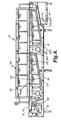
- FIG. 6 is a side elevational view of the apparatus of the present invention.
- FIG. 7 is a perspective view of an air supply unit of the present invention.
- FIG. 8 is an exploded perspective view of an air supply unit of the present invention.
- FIG. 9 is a top plan view of a conveyor and heated air plenum of the prior art.
- FIG. 10 is a top plan view of a conveyor and heated air plenum of the present invention.
- FIG. 11A is a front elevational view of the apparatus of the present invention.
- FIG. 11B is a detailed view of the indicated area in FIG. 11 A.
- FIG. 12 is a side elevational view of an air supply unit of the present invention.
- FIG. 13A is a perspective view of a second embodiment of the apparatus of the present invention, with side-by-side conveyor chains.
- FIG. 13B is a front elevational view of the apparatus of FIG. 13 A.
- FIG. 13C is a detailed view of the indicated area of FIG. 13 B.
- FIG. 14 is a perspective view of a heat tunnel using the embodiment of FIG. 13 A.
- FIG. 15 is similar to FIG. 14 , but in addition shows articles being shrink-wrapped within the heat tunnel.
- FIG. 16 is a perspective view of the heated air plenum of the present invention showing an embodiment with nozzles about the apertures.
- FIGS. 17-20 are perspective views of a heat tunnel of the present invention showing the use of an optional film separator.
- FIG. 21 is a perspective view through the heated air plenum showing another embodiment of the invention with air lanes.
- FIG. 22 is a perspective view of the embodiment of FIG. 21 .
- FIG. 23 is a cross-sectional view taken at approximately the lines 23 of FIG. 21 .
- the present invention is an apparatus 10 for applying heat to articles A and to enclose the articles A in shrink-wrap film F.
- the apparatus 10 ( FIGS. 4 , 5 , and 6 ) comprises a conveyor 12 having a plurality of first apertures 14 therethrough.
- a motor 16 drives the conveyor 12 in a first direction as shown by the arrows in FIG. 5 .
- the apparatus 10 further comprises a source of heated air 18 .
- the apparatus 10 further comprises ( FIG. 7 ) a heated air plenum 20 under the conveyor 12 and supporting the conveyor 12 , the plenum 20 having a top surface 22 having a plurality of second apertures 24 therethrough. It has been found that an optimal size for the second apertures 24 is about 7/16 inch to 7/32 inch . In this range, the flow of heated air through the apertures 24 is much less turbulent than with either larger or smaller aperture sizes. Specifically, this range of aperture size creates primarily a vertical air flow, while larger aperture sizes allow horizontal flow.
- the apparatus 10 further comprises ( FIG. 8 ) a fan 26 blowing heated air from the source of heated air 18 through the heated air plenum 20 , through the second apertures 24 , and through the first apertures 14 .
- the apparatus 10 further comprises a return air plenum 30 returning air to the source of heated air 18 .
- the apparatus 10 further comprises a shroud 32 partially enclosing the conveyor 12 along the first direction and spaced from the conveyor 12 at a displacement. With the conveyor 12 , shroud 32 forms a film shrinking area 34 between the conveyor 12 and the shroud 32 (FIG. 14 ).
- the heated air plenum 20 further comprises a bottom surface 25 spaced from and opposing the top surface 22 and forming a duct 36 therebetween.
- the duct 36 has a height 38 , and the height 38 progressively decreases along the first direction, as best seen in FIGS. 6 and 12 .
- the first apertures 14 and second apertures 24 are in substantial alignment as the conveyor 12 moves along the first direction.
- This structure is significantly different from the prior art ( FIG. 9 ) in which the first apertures and second apertures are substantially unaligned.
- the heated air passing therethrough only heats the conveyor 12 when the two sets of apertures 14 , 24 are unaligned. This creates a lower temperature on the conveyor 12 , which has important consequences as will be discussed below.
- the apparatus 10 further comprises a conveyor cooling fan 40 which also aids in keeping the temperature of the conveyor 12 significantly lower than in earlier devices.
- the apparatus 10 further comprises a side air duct 50 adjacent the conveyor 12 along the first direction, with the side air duct 50 transmitting heated air from the heated air plenum 20 .
- the side air duct 50 may optionally have a supplemental heat source 52 (FIG. 11 B), which may be an electrical heater.
- the apparatus 10 further comprises at least two side-by-side conveyor chains 12 a , 12 b running along the first direction.
- the apparatus 10 further comprises a center air duct 54 transmitting heated air from the heated air plenum 20 .
- the center air duct 54 may optionally have a supplemental heat source 56 , which may be an electrical heater.
- the displacement 60 at which the shroud 32 is spaced from the conveyor 12 is variable, thereby accommodating articles of various sizes.
- the apparatus 10 further comprises a means 62 for varying the displacement 60 .
- the means 62 may either be manual (e.g., a crank or screw) or it may be automatic (e.g., by a motor 62 a ).
- the present invention is an apparatus 110 for applying heated air to articles A and to enclose the articles A in shrink-wrap film F.
- the apparatus 110 ( FIGS. 4 , 5 , 6 , and 10 ) comprises a moving conveyor 112 having a plurality of first apertures 14 therethrough separated by link bars 15 .
- the apparatus 110 further comprises a source of heated air 18 .
- the apparatus 110 further comprises ( FIG. 7 ) a heated air plenum 20 under the conveyor 112 and supporting the conveyor chain 112 , the plenum 20 having a top surface 22 having a plurality of second apertures 24 therethrough.
- the first apertures 14 and second apertures 24 are in substantial alignment as the conveyor 112 moves along the first direction.
- the heated air passing therethrough only heats the conveyor 112 when the two sets of apertures 14 , 24 are unaligned. This creates a lower temperature on the conveyor 112 , which has important consequences as will be discussed below.
- the apparatus 110 further comprises a side air duct 50 adjacent the conveyor 112 along the first direction, with the side air duct 50 transmitting heated air from the heated air plenum 20 transversely across the conveyor 112 .
- the apparatus 110 further comprises a return air plenum 30 returning air to the source of heated air 18 .
- the apparatus 110 further comprises a shroud 32 partially enclosing the conveyor 112 and spaced from the conveyor 112 . With the conveyor 112 , shroud 32 defines a film shrinking area 34 between the conveyor 112 and the shroud 32 .
- the heated air plenum 20 is tapered vertically along the conveyor 112 in the direction of movement of the conveyor 112 , as best seen in FIGS. 6 and 12 .
- the apparatus 110 further comprises at least one additional conveyor chain 12 b.
- the apparatus 110 further comprises a center air duct 54 between the conveyor chains 12 a , 12 b transmitting heated air from the heated air plenum 20 transversely across the conveyor chains 12 a , 12 b.
- the invention is an apparatus 210 ( FIG. 4 ) for applying heated air to articles A enclosed in shrink-wrap film F.
- the apparatus 210 includes at least one air supply unit 220 , a conveyor 112 , and a heat shroud 32 spaced from the conveyor 112 , wherein multiple air supply units 220 can be provided along the conveyor 112 to create a heat tunnel of desired length.
- the air supply unit 220 further comprises a source of heated air 18 , a fan 26 , a heated air plenum 20 , air ducts 50 , and a return air plenum 30 .
- the apparatus 210 further comprises at least one additional conveyor chain 12 b.
- the apparatus 210 further comprises a center air duct 54 between the conveyor chains 12 a , 12 b transmitting heated air from the heated air plenum 20 transversely across the conveyor chains 12 a , 12 b.
- the displacement 60 between the shroud 32 and the conveyor 112 is variable, thereby accommodating articles of various sizes.
- the apparatus 110 , 210 further comprises means 62 for lowering and raising the shroud 32 relative to the conveyor chain 112 .
- the means 62 may either be manual (e.g., a crank or screw) or it may be automatic (e.g., by a motor 62 a ).
- the source of heated air 18 is removable from the air supply unit 220 .
- the source of heated air 18 is controlled to maintain a constant temperature in the heated air plenum 20 .
- the apparatus 210 further comprises a sensor 230 ( FIG. 6 ) in the heated air plenum 20 after the fan 26 , with the sensor 230 controlling the temperature of the source of heated air 18 .
- the fan 26 has a variable speed to adjust the flow of heated air through the heated air plenum 20 .
- the fan 26 is removable from the air supply unit 220 .
- the side air duct 50 has an adjustable opening.
- the side air duct 50 has a diffuser 51 .
- the air supply unit 220 is modular.
- a plurality of the modular air supply units 220 may be serially arranged thereby producing a heat tunnel of variable length, as best seen in FIGS. 4 , 5 , and 6 .
- the heated air plenum 20 is tapered in cross section transversely to the direction of heated air movement with the cross sectional area of the plenum 20 progressively decreasing away from the fan 26 as best seen in FIGS. 6 and 12 .
- the modular air supply unit 220 further comprises a retractable center air duct 54 receiving heated air from the heated air plenum 20 .
- FIG. 3 shows the articles A enclosed in shrink-wrap film 21 which has been pre-perforated, any type of shrink-wrap film F may be used to enclose the articles A.
- Articles A then move from the infeed conveyor to the conveyor 12 , 112 as in FIG. 3 and enter the apparatus 10 , 110 , and 210 shown in FIG. 3 .
- articles A move along the conveyor 12 , 112 within the apparatus 10 , 110 , 210 .
- heated air from the source of heated air 18 is driven by the fan 26 along the heated air plenum 20 . Heated air then exits the heated air plenum 20 through the second apertures 24 .
- the first apertures 14 which are in substantial alignment with the second apertures 24 , allow heated air to directly contact the shrink-wrap film F under the articles A, producing an air weld. Because the heated air does not contact the conveyor 12 , 112 except at the link bars 15 (as shown in FIG.
- the conveyor 12 , 112 remains much cooler than in previous devices. This prevents the shrink-wrap film F from sticking to the conveyor 12 , 112 .
- the lower chain temperature also allows the film lap seam under the articles A to be welded by the hot air, rather than by the hot chain which produces an undesirable chain weld. In addition, this prevents the chain itself from robbing heat from the heated air, so that the heated air produces a more efficient air weld on the shrink-wrap film F.
- Another benefit is that the conveyor 12 , 112 has a longer service life.
- the cooling fan 40 for the conveyor 12 , 112 may also be provided to increase these benefits.
- the present invention decreases the cross sectional area of the plenum 20 away from the fan 26 , thereby adjusting the volume of the plenum 20 in order to keep relatively constant pressure across the length of the plenum 20 .
- the specific size of the second apertures 24 and the alignment with the first apertures 14 produces significantly less turbulence in the heated air, so that a substantially vertical laminar air flow is produced. This in turn causes less fluttering of the shrink-wrap film, resulting in more aesthetically pleasing bulls eyes.
- the side air ducts 50 provide heated air directed at these openings.
- the optional, retractable center air duct 54 is provided to direct heated air at the open ends of the shrink-wrap film F facing the center of the conveyor 12 , 112 .
- Both the side air ducts 50 and the center air duct 54 may be provided with an adjustable opening to adjust the volume of heated air flowing out.
- a nozzle or diffuser may be provided to direct the heated air at the articles A.
- the film shrinking process can be optimally adjusted for the speed of incoming articles A.
- Further improvements include the ability to maintain the source of heated air 18 at a constant temperature in the heated air plenum 20 . This can be done by providing the sensor 230 ( FIG. 6 ) in the hot air plenum 20 , with the sensor 230 controlling the temperature of the source of heated air 18 .
- the speed of the fan 26 may be variable to adjust the flow of heated air through the heated air plenum 20 .
- the source of heated air 18 can be removed from the air supply unit 220 for service and/or replacement, as can the fan 26 .
- an entire air supply unit 220 can be removed from the heat tunnel and replaced.
- the second apertures 24 may have small nozzles 24 A (FIG. 16 ).
- the nozzles 24 A increase the length of the aperture 24 and reduce the amount of horizontal air flow that is allowed to exit the aperture 24 .
- the resulting flow from the apertures 24 is thus more vertical, causing less disturbance to the shrink wrap film F.
- an optional film separator 250 may be added at the infeed end of the heat tunnel as shown in FIGS. 17-20 .
- the film separator 250 ensures that the film of adjacent packages does not melt and stick together.
- the film separator 250 extends into the heat tunnel far enough to ensure that the lower portion of the unsupported film, which extends beyond the articles, has started to shrink and draw away from that of the adjacent package.
- the separator 250 can be mounted on top of the conveyor 12 , 112 ( FIGS. 17-18 ) or it may be mounted between a set of conveyor chains 12 a , 12 b (FIGS. 19 - 20 ).
- an airflow control mechanism 260 may be added to the heated air plenum 20 to vary the amount of heated air sent through the second apertures 24 across the width of the plenum 20 . It has been found that, in the case of perforated film, the amount of airflow required to separate the film at the perforation may be too much for the bottom of the package. This may cause excessive shrink and create holes in the film.
- the airflow control mechanism 260 preferably comprises air lanes 262 in the heated air plenum 20 under the conveyor 12 , 112 . These air lanes 262 will provide heated air to one or more columns of the second apertures 24 across the width of the plenum 20 .
- each air lane 262 may be independently adjustable through the use of one or more baffles 264 .
- the air lanes 262 a under the weakened film and on either side of the outer packages will be open to allow maximum energy through the conveyor 12 in order to separate the packages and shrink the film.
- the lanes 262 b directly underneath the packages will be restricted so that the lap seam on the bottom of the package is still welded, but the film is not damaged due to excessive heat.
- the drawings represent one example of the use of air lanes, and that other baffle configurations are contemplated to be within the scope of the invention.
Abstract
Description
Claims (21)
Priority Applications (10)
| Application Number | Priority Date | Filing Date | Title |
|---|---|---|---|
| US10/680,538 US7155876B2 (en) | 2003-05-23 | 2003-10-07 | Heat tunnel for film shrinking |
| CNA2004800364125A CN1890153A (en) | 2003-10-07 | 2004-10-06 | Heat tunnel for film shrinking |
| MXPA06003842A MXPA06003842A (en) | 2003-10-07 | 2004-10-06 | Heat tunnel for film shrinking. |
| MX2009009928A MX353726B (en) | 2003-10-07 | 2004-10-06 | Heat tunnel for film shrinking. |
| EP04794222A EP1678038B1 (en) | 2003-05-23 | 2004-10-06 | Heat tunnel for film shrinking |
| PCT/US2004/032806 WO2005037652A1 (en) | 2003-05-23 | 2004-10-06 | Heat tunnel for film shrinking |
| US11/021,976 US7823366B2 (en) | 2003-10-07 | 2004-12-22 | Apparatus and method for selective processing of materials with radiant energy |
| US11/496,608 US7269929B2 (en) | 2003-05-23 | 2006-07-31 | Heat tunnel for film shrinking |
| US11/856,184 US20080092494A1 (en) | 2003-05-23 | 2007-09-17 | Heat Tunnel for Film-Shrinking |
| US12/642,328 US8051629B2 (en) | 2003-05-23 | 2009-12-18 | Heat tunnel for film shrinking |
Applications Claiming Priority (2)
| Application Number | Priority Date | Filing Date | Title |
|---|---|---|---|
| US47337203P | 2003-05-23 | 2003-05-23 | |
| US10/680,538 US7155876B2 (en) | 2003-05-23 | 2003-10-07 | Heat tunnel for film shrinking |
Related Child Applications (3)
| Application Number | Title | Priority Date | Filing Date |
|---|---|---|---|
| US11/021,976 Continuation-In-Part US7823366B2 (en) | 2003-10-07 | 2004-12-22 | Apparatus and method for selective processing of materials with radiant energy |
| US29/227,609 Continuation USD517578S1 (en) | 2003-10-07 | 2005-04-13 | Shroud for a heat tunnel or the like |
| US11/496,608 Division US7269929B2 (en) | 2003-05-23 | 2006-07-31 | Heat tunnel for film shrinking |
Publications (2)
| Publication Number | Publication Date |
|---|---|
| US20040231301A1 US20040231301A1 (en) | 2004-11-25 |
| US7155876B2 true US7155876B2 (en) | 2007-01-02 |
Family
ID=33457456
Family Applications (4)
| Application Number | Title | Priority Date | Filing Date |
|---|---|---|---|
| US10/680,538 Expired - Lifetime US7155876B2 (en) | 2003-05-23 | 2003-10-07 | Heat tunnel for film shrinking |
| US11/496,608 Expired - Lifetime US7269929B2 (en) | 2003-05-23 | 2006-07-31 | Heat tunnel for film shrinking |
| US11/856,184 Abandoned US20080092494A1 (en) | 2003-05-23 | 2007-09-17 | Heat Tunnel for Film-Shrinking |
| US12/642,328 Expired - Lifetime US8051629B2 (en) | 2003-05-23 | 2009-12-18 | Heat tunnel for film shrinking |
Family Applications After (3)
| Application Number | Title | Priority Date | Filing Date |
|---|---|---|---|
| US11/496,608 Expired - Lifetime US7269929B2 (en) | 2003-05-23 | 2006-07-31 | Heat tunnel for film shrinking |
| US11/856,184 Abandoned US20080092494A1 (en) | 2003-05-23 | 2007-09-17 | Heat Tunnel for Film-Shrinking |
| US12/642,328 Expired - Lifetime US8051629B2 (en) | 2003-05-23 | 2009-12-18 | Heat tunnel for film shrinking |
Country Status (3)
| Country | Link |
|---|---|
| US (4) | US7155876B2 (en) |
| EP (1) | EP1678038B1 (en) |
| WO (1) | WO2005037652A1 (en) |
Cited By (35)
| Publication number | Priority date | Publication date | Assignee | Title |
|---|---|---|---|---|
| US20070215506A1 (en) * | 2006-03-17 | 2007-09-20 | Hartness Thomas P | Heat-shrinkable holder for articles, heat-shrinkable package of articles, and method of packaging articles |
| US20080272013A1 (en) * | 2006-03-17 | 2008-11-06 | Hartness International, Inc. | Heat-shrinkable holder for articles, heat-shrinkable package of articles, heat-shrinkable sleeve for articles, and method and device for packaging and sleeving articles |
| US20080305203A1 (en) * | 2007-06-11 | 2008-12-11 | Sidel Participations | Installation for heating the bodies of preforms for blow-moulding containers |
| US20090214690A1 (en) * | 2004-11-22 | 2009-08-27 | Sidel Participations | Method and installation for the production of containers |
| US20100089906A1 (en) * | 2007-03-02 | 2010-04-15 | Sidel Participations | heating plastics via infrared radiation |
| US20100293901A1 (en) * | 2009-05-20 | 2010-11-25 | Martin Malthouse | Shrink Systems for Labels |
| US7850003B2 (en) | 2006-03-17 | 2010-12-14 | Illinois Tool Works Inc. | Heat-shrinkable holder for articles, heat-shrinkable package of articles, and method of packaging articles |
| US20110088354A1 (en) * | 2009-10-16 | 2011-04-21 | Ulma Packaging Technological Center, S.Coop. | Packaging Apparatus and Processes |
| US20110139664A1 (en) * | 2008-10-22 | 2011-06-16 | Khs Gmbh | Method and device for the production of a packaged unit |
| US20110232239A1 (en) * | 2010-03-24 | 2011-09-29 | Multivac Sepp Haggenmuller Gmbh & Co. Kg | Device for transporting objects |
| US20120018035A1 (en) * | 2010-07-20 | 2012-01-26 | Krones Ag | Arrangement and method for coupling several groups of machine assemblies of a container processing device |
| US20140020344A1 (en) * | 2012-07-20 | 2014-01-23 | Tzu-Chin Hung | Shrink film heating device |
| US20140041341A1 (en) * | 2011-05-10 | 2014-02-13 | Fuji Seal International, Inc. | Apparatus and method for heat shrinking a film wrapping an object |
| US9988763B2 (en) | 2014-11-12 | 2018-06-05 | First Quality Tissue, Llc | Cannabis fiber, absorbent cellulosic structures containing cannabis fiber and methods of making the same |
| US9995005B2 (en) | 2012-08-03 | 2018-06-12 | First Quality Tissue, Llc | Soft through air dried tissue |
| US10099425B2 (en) | 2014-12-05 | 2018-10-16 | Structured I, Llc | Manufacturing process for papermaking belts using 3D printing technology |
| RU186221U1 (en) * | 2018-09-26 | 2019-01-11 | Федеральное государственное бюджетное образовательное учреждение образования "Владимирский Государственный Университет имени Александра Григорьевича и Николая Григорьевича Столетовых" (ВлГУ) | Planetary roller gear |
| US10208426B2 (en) | 2016-02-11 | 2019-02-19 | Structured I, Llc | Belt or fabric including polymeric layer for papermaking machine |
| US10273635B2 (en) | 2014-11-24 | 2019-04-30 | First Quality Tissue, Llc | Soft tissue produced using a structured fabric and energy efficient pressing |
| US10301779B2 (en) | 2016-04-27 | 2019-05-28 | First Quality Tissue, Llc | Soft, low lint, through air dried tissue and method of forming the same |
| US10422078B2 (en) | 2016-09-12 | 2019-09-24 | Structured I, Llc | Former of water laid asset that utilizes a structured fabric as the outer wire |
| US10422082B2 (en) | 2016-08-26 | 2019-09-24 | Structured I, Llc | Method of producing absorbent structures with high wet strength, absorbency, and softness |
| US10538882B2 (en) | 2015-10-13 | 2020-01-21 | Structured I, Llc | Disposable towel produced with large volume surface depressions |
| US10544547B2 (en) | 2015-10-13 | 2020-01-28 | First Quality Tissue, Llc | Disposable towel produced with large volume surface depressions |
| US10619309B2 (en) | 2017-08-23 | 2020-04-14 | Structured I, Llc | Tissue product made using laser engraved structuring belt |
| US11084616B2 (en) | 2014-10-31 | 2021-08-10 | Arpac, Llc | Shrink wrap tunnel |
| US11220394B2 (en) | 2015-10-14 | 2022-01-11 | First Quality Tissue, Llc | Bundled product and system |
| US11391000B2 (en) | 2014-05-16 | 2022-07-19 | First Quality Tissue, Llc | Flushable wipe and method of forming the same |
| US11505898B2 (en) | 2018-06-20 | 2022-11-22 | First Quality Tissue Se, Llc | Laminated paper machine clothing |
| US11524805B2 (en) * | 2018-07-24 | 2022-12-13 | Khs Gmbh | Shrink-wrapping arrangement for shrink wrapping containers or packages, including bottles, boxes, cans, or similar containers or packages, and a method of operating a shrink-wrapping arrangement |
| US11549753B2 (en) | 2017-01-24 | 2023-01-10 | Illinois Tool Works Inc. | Laminar flow shrink oven |
| US11583489B2 (en) | 2016-11-18 | 2023-02-21 | First Quality Tissue, Llc | Flushable wipe and method of forming the same |
| US11697538B2 (en) | 2018-06-21 | 2023-07-11 | First Quality Tissue, Llc | Bundled product and system and method for forming the same |
| US11738927B2 (en) | 2018-06-21 | 2023-08-29 | First Quality Tissue, Llc | Bundled product and system and method for forming the same |
| US11959226B2 (en) | 2020-12-15 | 2024-04-16 | First Quality Tissue, Llc | Soft tissue produced using a structured fabric and energy efficient pressing |
Families Citing this family (35)
| Publication number | Priority date | Publication date | Assignee | Title |
|---|---|---|---|---|
| US7762413B2 (en) * | 2005-04-04 | 2010-07-27 | Karen May Song | Nursing bottle holder |
| US20090004615A1 (en) * | 2007-06-27 | 2009-01-01 | Graham Robert G | Roller hearth calcining furnace and method of use |
| DE202007018402U1 (en) * | 2007-10-16 | 2008-07-10 | Krones Ag | shrink tunnel |
| DE102009044465A1 (en) * | 2009-11-09 | 2011-05-12 | Krones Ag | shrink tunnel |
| DE102010000192A1 (en) * | 2010-01-26 | 2011-07-28 | Krones Ag, 93073 | shrink tunnel |
| US8829396B2 (en) * | 2010-11-30 | 2014-09-09 | Tp Solar, Inc. | Finger drives for IR wafer processing equipment conveyors and lateral differential temperature profile methods |
| US8816253B2 (en) * | 2011-01-21 | 2014-08-26 | Tp Solar, Inc. | Dual independent transport systems for IR conveyor furnaces and methods of firing thin work pieces |
| EP2546154A1 (en) * | 2011-07-12 | 2013-01-16 | Cryovac, Inc. | Packaging apparatus and method of expelling gas |
| US20130143172A1 (en) * | 2011-12-02 | 2013-06-06 | Wildcat Discovery Technologies, Inc. | High throughput furnace |
| US9027313B2 (en) * | 2012-04-30 | 2015-05-12 | Reelex Packaging Solutions, Inc. | Apparatus for dividing heat-shrinkable plastic film into different temperature regions |
| US8910396B1 (en) * | 2012-05-08 | 2014-12-16 | SEETECH Systems, Inc. | Conveyor tunnel |
| FR2993247B1 (en) * | 2012-07-12 | 2014-07-04 | Sleever Int | THERMORETRACTION INSTALLATION COMPRISING MEANS OF HEAT DIFFUSION FORMING A UNITARY ASSEMBLY. |
| EP2722280A1 (en) * | 2012-10-17 | 2014-04-23 | Cryovac, Inc. | Packaging process and packaging apparatus |
| US9162787B2 (en) * | 2012-12-05 | 2015-10-20 | Tzu-Chin Hung | Tangential airstream heat shrinking device of plastic film |
| DE102013101477A1 (en) * | 2013-02-14 | 2014-08-14 | Krones Aktiengesellschaft | SHRINKING DEVICE |
| DE102013101782A1 (en) * | 2013-02-22 | 2014-08-28 | Khs Gmbh | Shrink tunnel plant and an associated method for shrinking a shrink film on packing formations |
| US9103595B2 (en) | 2013-03-14 | 2015-08-11 | Arpac, Llc | Shrink wrap tunnel with dynamic width adjustment |
| DE102013103863A1 (en) * | 2013-04-17 | 2014-10-23 | Krones Aktiengesellschaft | Shrinking device and method for adjusting a shrinking device |
| CA2836147C (en) * | 2013-12-05 | 2017-10-31 | Carlos Calpe Gargallo | Body dryer assembly and bathtub or shower stall enclosure partition assembly |
| US20150239593A1 (en) * | 2014-02-27 | 2015-08-27 | Olivier Cerf | Apparatus and Process for Preventing Printed Film Distortion during Heat Shrinking |
| DE102014104646B4 (en) * | 2014-04-02 | 2018-10-31 | Krones Aktiengesellschaft | Device for shrinking film onto articles |
| JP6429566B2 (en) * | 2014-09-30 | 2018-11-28 | 大王製紙株式会社 | Tissue paper container packaging method and tissue paper container packaging apparatus |
| WO2016170695A1 (en) * | 2015-04-20 | 2016-10-27 | 大森機械工業 株式会社 | Packaging machine |
| US20170015080A1 (en) * | 2015-07-15 | 2017-01-19 | Mp Global Products, L.L.C. | Method of making an insulated mailer |
| DE102015111563A1 (en) | 2015-07-16 | 2017-01-19 | Krones Aktiengesellschaft | shrinker |
| USD790614S1 (en) * | 2015-08-06 | 2017-06-27 | Haimer Gmbh | Heat shrinking machine |
| USD791207S1 (en) * | 2015-08-06 | 2017-07-04 | Haimer Gmbh | Heat shrinking machine |
| US9951991B2 (en) | 2015-08-31 | 2018-04-24 | M&R Printing Equipment, Inc. | System and method for dynamically adjusting dryer belt speed |
| US20180073805A1 (en) * | 2016-09-13 | 2018-03-15 | M&R Printing Equipment, Inc. | Multiple Belt and Multiple Zone Textile Dryer |
| WO2018187458A2 (en) | 2017-04-07 | 2018-10-11 | The Middleby Corporation | Conveyor oven heat delivery system |
| FR3070376B1 (en) * | 2017-08-30 | 2021-04-16 | C E R M E X Constructions Etudes Et Rech De Materiels Pour Lemballage Dexpedition | OPERATION OF A RETRACTION DEVICE OF AN AUTOMATIC SHRINDER |
| US11661225B2 (en) * | 2018-10-10 | 2023-05-30 | Illinois Tool Works Inc. | Center divider for shrink oven |
| US11369117B2 (en) * | 2018-12-20 | 2022-06-28 | The Middleby Corporation | Conveyor oven air system |
| US11540496B1 (en) * | 2020-03-05 | 2023-01-03 | Stuart Suydam | Method and apparatus for increasing honey harvest efficiency |
| CN112607133A (en) * | 2020-12-04 | 2021-04-06 | 宁波大学 | Method for thermal shrinkage packaging of battery |
Citations (14)
| Publication number | Priority date | Publication date | Assignee | Title |
|---|---|---|---|---|
| US3222800A (en) * | 1962-05-29 | 1965-12-14 | Weldotron Corp | Apparatus for shrinking wrappers of packages |
| US3349502A (en) * | 1964-08-11 | 1967-10-31 | Trescott Company Inc | Apparatus for shrinking film-wrappings on articles |
| US3545165A (en) | 1968-12-30 | 1970-12-08 | Du Pont | Packaging method and apparatus |
| US3721804A (en) * | 1970-12-16 | 1973-03-20 | Tsi Inc | Apparatus for sealing and shrinking plastic film |
| US3830036A (en) * | 1973-02-20 | 1974-08-20 | Harkess K D B A Ideanamics | Grocery packaging machine |
| US3866331A (en) * | 1974-03-07 | 1975-02-18 | Itp Corp | Flow control shrink wrap tunnel |
| US3897671A (en) * | 1973-08-31 | 1975-08-05 | Comptex | Apparatus and method for covering a load on a pallet |
| US5050368A (en) * | 1990-01-11 | 1991-09-24 | Tokiwa Kogyo Co., Ltd. | Shrink packaging apparatus |
| US5765336A (en) * | 1995-11-13 | 1998-06-16 | Neagle; Claud Andrew | Single and dual lane traypacker and shrinkwrapper |
| US5771662A (en) | 1996-06-28 | 1998-06-30 | Douglas Machine Limited Liability Company | Apparatus and methods for producing shrink wrap packaging |
| USD481049S1 (en) | 2002-09-12 | 2003-10-21 | Lantech Management Corp. And Lantech Holding Corp. | Shrink wrap tunnel |
| US6648634B2 (en) * | 2001-08-29 | 2003-11-18 | Paolo Nava | Thermoshrinking tunnel oven for making thermoshrinking plastic material film package and the packaging method performed thereby |
| US6689180B1 (en) * | 2002-11-14 | 2004-02-10 | Benison & Co., Ltd. | Hot air flow control device of heat-shrinking film packaging machine |
| US20040123566A1 (en) | 2002-12-30 | 2004-07-01 | Lantech Management Corp. | Shrink wrap apparatus and method of shrink wrapping products |
Family Cites Families (24)
| Publication number | Priority date | Publication date | Assignee | Title |
|---|---|---|---|---|
| US3330094A (en) * | 1963-02-07 | 1967-07-11 | Grace W R & Co | Apparatus for applying covers to containers |
| US3399506A (en) * | 1965-04-01 | 1968-09-03 | Grace W R & Co | Process and apparatus for simultaneously heat sealing and heat shrinking film |
| US3357153A (en) * | 1965-07-23 | 1967-12-12 | Grace W R & Co | Process and apparatus for heat shrinking film |
| DE1786483A1 (en) * | 1966-01-24 | 1972-02-24 | Platmanufaktur Ab | Device for distributing packaging units or the like to a machine for group-wise packing of such packaging units or the like. |
| AU1413566A (en) * | 1966-11-18 | 1969-03-13 | W. R. Grace Australia | Packaging |
| US3572004A (en) * | 1968-07-15 | 1971-03-23 | Du Pont | Packaging apparatus |
| US3744146A (en) * | 1970-06-02 | 1973-07-10 | Mill Eng Inc | Shrink tunnel |
| US3808767A (en) * | 1971-01-11 | 1974-05-07 | Master Packaging Equipment Inc | Methods of and apparatus for shrink packaging |
| US3866386A (en) * | 1972-01-17 | 1975-02-18 | Robert H Ganz | Method and apparatus for making a shrink pack |
| US3834525A (en) * | 1972-08-10 | 1974-09-10 | Ganz Brothers Inc | Shrink-package construction |
| US3808702A (en) * | 1973-03-15 | 1974-05-07 | Gilbreth Co | Heat shrink tunnel for ensuring uniform shrinkage of heat shrinkable bands on articles of various sizes |
| US3965645A (en) * | 1974-08-26 | 1976-06-29 | Ganz Robert H | Package tightener and method |
| US4365456A (en) * | 1976-05-05 | 1982-12-28 | The Mead Corporation | Method of and apparatus for packaging |
| US4172348A (en) * | 1978-04-20 | 1979-10-30 | Ganz Brothers, Inc. | Package and apparatus and method for making same |
| US4263725A (en) * | 1979-07-03 | 1981-04-28 | Ganz Brothers, Inc. | Shrink tunnel |
| FR2524131A1 (en) | 1982-03-25 | 1983-09-30 | Glaskuhl Sa | APPARATUS FOR THERMALLY PROCESSING OBJECTS BY CONVECTION |
| US4597247A (en) * | 1985-10-15 | 1986-07-01 | The Mead Corporation | Method and apparatus for applying controlled heat to a group of articles disposed within a shrink film wrapper |
| JPH01252886A (en) | 1988-03-31 | 1989-10-09 | Central Glass Co Ltd | Heat working furnace and heat treatment effected thereby |
| DE3924871A1 (en) | 1989-07-27 | 1991-02-07 | Dieter Kicherer | Shrinking tunnel for foil wrappings - uses gaseous heat transfer medium with adjustable heat content |
| US5062217A (en) * | 1990-11-13 | 1991-11-05 | Ossid Corporation | Selective sequential shrink apparatus and process |
| US5088921A (en) | 1990-11-14 | 1992-02-18 | Libbey-Owens-Ford Co. | Heat treatment furnace |
| US6854242B2 (en) | 2000-10-30 | 2005-02-15 | Stork Fabricators, Inc. | Modular shrink-wrap machine |
| US7325374B2 (en) | 2004-11-02 | 2008-02-05 | Shanklin Corporation | Modular infeeds for automatic forms/fill/seal equipment |
| DE102007057237A1 (en) | 2007-11-26 | 2009-05-28 | Umicore Ag & Co. Kg | Tunnel kiln for the temperature treatment of goods |
-
2003
- 2003-10-07 US US10/680,538 patent/US7155876B2/en not_active Expired - Lifetime
-
2004
- 2004-10-06 WO PCT/US2004/032806 patent/WO2005037652A1/en active Application Filing
- 2004-10-06 EP EP04794222A patent/EP1678038B1/en active Active
-
2006
- 2006-07-31 US US11/496,608 patent/US7269929B2/en not_active Expired - Lifetime
-
2007
- 2007-09-17 US US11/856,184 patent/US20080092494A1/en not_active Abandoned
-
2009
- 2009-12-18 US US12/642,328 patent/US8051629B2/en not_active Expired - Lifetime
Patent Citations (14)
| Publication number | Priority date | Publication date | Assignee | Title |
|---|---|---|---|---|
| US3222800A (en) * | 1962-05-29 | 1965-12-14 | Weldotron Corp | Apparatus for shrinking wrappers of packages |
| US3349502A (en) * | 1964-08-11 | 1967-10-31 | Trescott Company Inc | Apparatus for shrinking film-wrappings on articles |
| US3545165A (en) | 1968-12-30 | 1970-12-08 | Du Pont | Packaging method and apparatus |
| US3721804A (en) * | 1970-12-16 | 1973-03-20 | Tsi Inc | Apparatus for sealing and shrinking plastic film |
| US3830036A (en) * | 1973-02-20 | 1974-08-20 | Harkess K D B A Ideanamics | Grocery packaging machine |
| US3897671A (en) * | 1973-08-31 | 1975-08-05 | Comptex | Apparatus and method for covering a load on a pallet |
| US3866331A (en) * | 1974-03-07 | 1975-02-18 | Itp Corp | Flow control shrink wrap tunnel |
| US5050368A (en) * | 1990-01-11 | 1991-09-24 | Tokiwa Kogyo Co., Ltd. | Shrink packaging apparatus |
| US5765336A (en) * | 1995-11-13 | 1998-06-16 | Neagle; Claud Andrew | Single and dual lane traypacker and shrinkwrapper |
| US5771662A (en) | 1996-06-28 | 1998-06-30 | Douglas Machine Limited Liability Company | Apparatus and methods for producing shrink wrap packaging |
| US6648634B2 (en) * | 2001-08-29 | 2003-11-18 | Paolo Nava | Thermoshrinking tunnel oven for making thermoshrinking plastic material film package and the packaging method performed thereby |
| USD481049S1 (en) | 2002-09-12 | 2003-10-21 | Lantech Management Corp. And Lantech Holding Corp. | Shrink wrap tunnel |
| US6689180B1 (en) * | 2002-11-14 | 2004-02-10 | Benison & Co., Ltd. | Hot air flow control device of heat-shrinking film packaging machine |
| US20040123566A1 (en) | 2002-12-30 | 2004-07-01 | Lantech Management Corp. | Shrink wrap apparatus and method of shrink wrapping products |
Cited By (68)
| Publication number | Priority date | Publication date | Assignee | Title |
|---|---|---|---|---|
| US20100072673A1 (en) * | 2004-11-22 | 2010-03-25 | Sidel Participations | Method and installation for the production of containers |
| US8354051B2 (en) | 2004-11-22 | 2013-01-15 | Sidel Participations | Method and installation for the production of containers |
| US8303290B2 (en) | 2004-11-22 | 2012-11-06 | Sidel Participations | Method and installation for the production of containers |
| US20090214690A1 (en) * | 2004-11-22 | 2009-08-27 | Sidel Participations | Method and installation for the production of containers |
| US7850003B2 (en) | 2006-03-17 | 2010-12-14 | Illinois Tool Works Inc. | Heat-shrinkable holder for articles, heat-shrinkable package of articles, and method of packaging articles |
| US20110056175A1 (en) * | 2006-03-17 | 2011-03-10 | Hartness International, Inc. | Heat-Shrinkable Holder for Articles, Heat-Shrinkable Package of Articles, Heat-Shrinkable Sleeve for Articles and Method and Device for Packaging and Sleeving Articles |
| US7832553B2 (en) | 2006-03-17 | 2010-11-16 | Illinois Tool Works Inc. | Heat-shrinkable holder for articles, heat-shrinkable package of articles, heat-shrinkable sleeve for articles, and method and device for packaging and sleeving articles |
| US20080272013A1 (en) * | 2006-03-17 | 2008-11-06 | Hartness International, Inc. | Heat-shrinkable holder for articles, heat-shrinkable package of articles, heat-shrinkable sleeve for articles, and method and device for packaging and sleeving articles |
| US20070215506A1 (en) * | 2006-03-17 | 2007-09-20 | Hartness Thomas P | Heat-shrinkable holder for articles, heat-shrinkable package of articles, and method of packaging articles |
| US7861490B2 (en) * | 2006-03-17 | 2011-01-04 | Illinois Tool Works Inc. | Method of packaging articles |
| US8546277B2 (en) | 2007-03-02 | 2013-10-01 | Sidel Participations | Heating plastics via infrared radiation |
| US20100089906A1 (en) * | 2007-03-02 | 2010-04-15 | Sidel Participations | heating plastics via infrared radiation |
| US20080305203A1 (en) * | 2007-06-11 | 2008-12-11 | Sidel Participations | Installation for heating the bodies of preforms for blow-moulding containers |
| US8662876B2 (en) | 2007-06-11 | 2014-03-04 | Sidel Participations | Installation for heating the bodies of preforms for blow-moulding containers |
| US20110139664A1 (en) * | 2008-10-22 | 2011-06-16 | Khs Gmbh | Method and device for the production of a packaged unit |
| US9926089B2 (en) * | 2008-10-22 | 2018-03-27 | Khs Gmbh | Method and device for the production of a packaged unit |
| US20100293901A1 (en) * | 2009-05-20 | 2010-11-25 | Martin Malthouse | Shrink Systems for Labels |
| US20110088354A1 (en) * | 2009-10-16 | 2011-04-21 | Ulma Packaging Technological Center, S.Coop. | Packaging Apparatus and Processes |
| US20110232239A1 (en) * | 2010-03-24 | 2011-09-29 | Multivac Sepp Haggenmuller Gmbh & Co. Kg | Device for transporting objects |
| US20120018035A1 (en) * | 2010-07-20 | 2012-01-26 | Krones Ag | Arrangement and method for coupling several groups of machine assemblies of a container processing device |
| US9284083B2 (en) * | 2010-07-20 | 2016-03-15 | Krones Ag | Arrangement and method for coupling several groups of machine assemblies of a container processing device |
| US20140041341A1 (en) * | 2011-05-10 | 2014-02-13 | Fuji Seal International, Inc. | Apparatus and method for heat shrinking a film wrapping an object |
| US20140020344A1 (en) * | 2012-07-20 | 2014-01-23 | Tzu-Chin Hung | Shrink film heating device |
| US9995005B2 (en) | 2012-08-03 | 2018-06-12 | First Quality Tissue, Llc | Soft through air dried tissue |
| US10190263B2 (en) | 2012-08-03 | 2019-01-29 | First Quality Tissue, Llc | Soft through air dried tissue |
| US10570570B2 (en) | 2012-08-03 | 2020-02-25 | First Quality Tissue, Llc | Soft through air dried tissue |
| US11391000B2 (en) | 2014-05-16 | 2022-07-19 | First Quality Tissue, Llc | Flushable wipe and method of forming the same |
| US11084616B2 (en) | 2014-10-31 | 2021-08-10 | Arpac, Llc | Shrink wrap tunnel |
| US9988763B2 (en) | 2014-11-12 | 2018-06-05 | First Quality Tissue, Llc | Cannabis fiber, absorbent cellulosic structures containing cannabis fiber and methods of making the same |
| US10900176B2 (en) | 2014-11-24 | 2021-01-26 | First Quality Tissue, Llc | Soft tissue produced using a structured fabric and energy efficient pressing |
| US11807992B2 (en) | 2014-11-24 | 2023-11-07 | First Quality Tissue, Llc | Soft tissue produced using a structured fabric and energy efficient pressing |
| US10273635B2 (en) | 2014-11-24 | 2019-04-30 | First Quality Tissue, Llc | Soft tissue produced using a structured fabric and energy efficient pressing |
| US10099425B2 (en) | 2014-12-05 | 2018-10-16 | Structured I, Llc | Manufacturing process for papermaking belts using 3D printing technology |
| US11752688B2 (en) | 2014-12-05 | 2023-09-12 | Structured I, Llc | Manufacturing process for papermaking belts using 3D printing technology |
| US10675810B2 (en) | 2014-12-05 | 2020-06-09 | Structured I, Llc | Manufacturing process for papermaking belts using 3D printing technology |
| US10538882B2 (en) | 2015-10-13 | 2020-01-21 | Structured I, Llc | Disposable towel produced with large volume surface depressions |
| US10544547B2 (en) | 2015-10-13 | 2020-01-28 | First Quality Tissue, Llc | Disposable towel produced with large volume surface depressions |
| US11242656B2 (en) | 2015-10-13 | 2022-02-08 | First Quality Tissue, Llc | Disposable towel produced with large volume surface depressions |
| US10954636B2 (en) | 2015-10-13 | 2021-03-23 | First Quality Tissue, Llc | Disposable towel produced with large volume surface depressions |
| US10954635B2 (en) | 2015-10-13 | 2021-03-23 | First Quality Tissue, Llc | Disposable towel produced with large volume surface depressions |
| US11577906B2 (en) | 2015-10-14 | 2023-02-14 | First Quality Tissue, Llc | Bundled product and system |
| US11220394B2 (en) | 2015-10-14 | 2022-01-11 | First Quality Tissue, Llc | Bundled product and system |
| US11028534B2 (en) | 2016-02-11 | 2021-06-08 | Structured I, Llc | Belt or fabric including polymeric layer for papermaking machine |
| US10787767B2 (en) | 2016-02-11 | 2020-09-29 | Structured I, Llc | Belt or fabric including polymeric layer for papermaking machine |
| US10208426B2 (en) | 2016-02-11 | 2019-02-19 | Structured I, Llc | Belt or fabric including polymeric layer for papermaking machine |
| US11634865B2 (en) | 2016-02-11 | 2023-04-25 | Structured I, Llc | Belt or fabric including polymeric layer for papermaking machine |
| US10301779B2 (en) | 2016-04-27 | 2019-05-28 | First Quality Tissue, Llc | Soft, low lint, through air dried tissue and method of forming the same |
| US10858786B2 (en) | 2016-04-27 | 2020-12-08 | First Quality Tissue, Llc | Soft, low lint, through air dried tissue and method of forming the same |
| US10941525B2 (en) | 2016-04-27 | 2021-03-09 | First Quality Tissue, Llc | Soft, low lint, through air dried tissue and method of forming the same |
| US10844548B2 (en) | 2016-04-27 | 2020-11-24 | First Quality Tissue, Llc | Soft, low lint, through air dried tissue and method of forming the same |
| US11674266B2 (en) | 2016-04-27 | 2023-06-13 | First Quality Tissue, Llc | Soft, low lint, through air dried tissue and method of forming the same |
| US11668052B2 (en) | 2016-04-27 | 2023-06-06 | First Quality Tissue, Llc | Soft, low lint, through air dried tissue and method of forming the same |
| US10982392B2 (en) | 2016-08-26 | 2021-04-20 | Structured I, Llc | Absorbent structures with high wet strength, absorbency, and softness |
| US11725345B2 (en) | 2016-08-26 | 2023-08-15 | Structured I, Llc | Method of producing absorbent structures with high wet strength, absorbency, and softness |
| US10422082B2 (en) | 2016-08-26 | 2019-09-24 | Structured I, Llc | Method of producing absorbent structures with high wet strength, absorbency, and softness |
| US11098448B2 (en) | 2016-09-12 | 2021-08-24 | Structured I, Llc | Former of water laid asset that utilizes a structured fabric as the outer wire |
| US11913170B2 (en) | 2016-09-12 | 2024-02-27 | Structured I, Llc | Former of water laid asset that utilizes a structured fabric as the outer wire |
| US10422078B2 (en) | 2016-09-12 | 2019-09-24 | Structured I, Llc | Former of water laid asset that utilizes a structured fabric as the outer wire |
| US11583489B2 (en) | 2016-11-18 | 2023-02-21 | First Quality Tissue, Llc | Flushable wipe and method of forming the same |
| US11549753B2 (en) | 2017-01-24 | 2023-01-10 | Illinois Tool Works Inc. | Laminar flow shrink oven |
| US10619309B2 (en) | 2017-08-23 | 2020-04-14 | Structured I, Llc | Tissue product made using laser engraved structuring belt |
| US11286622B2 (en) | 2017-08-23 | 2022-03-29 | Structured I, Llc | Tissue product made using laser engraved structuring belt |
| US11505898B2 (en) | 2018-06-20 | 2022-11-22 | First Quality Tissue Se, Llc | Laminated paper machine clothing |
| US11697538B2 (en) | 2018-06-21 | 2023-07-11 | First Quality Tissue, Llc | Bundled product and system and method for forming the same |
| US11738927B2 (en) | 2018-06-21 | 2023-08-29 | First Quality Tissue, Llc | Bundled product and system and method for forming the same |
| US11524805B2 (en) * | 2018-07-24 | 2022-12-13 | Khs Gmbh | Shrink-wrapping arrangement for shrink wrapping containers or packages, including bottles, boxes, cans, or similar containers or packages, and a method of operating a shrink-wrapping arrangement |
| RU186221U1 (en) * | 2018-09-26 | 2019-01-11 | Федеральное государственное бюджетное образовательное учреждение образования "Владимирский Государственный Университет имени Александра Григорьевича и Николая Григорьевича Столетовых" (ВлГУ) | Planetary roller gear |
| US11959226B2 (en) | 2020-12-15 | 2024-04-16 | First Quality Tissue, Llc | Soft tissue produced using a structured fabric and energy efficient pressing |
Also Published As
| Publication number | Publication date |
|---|---|
| US8051629B2 (en) | 2011-11-08 |
| US20040231301A1 (en) | 2004-11-25 |
| EP1678038B1 (en) | 2012-12-05 |
| EP1678038A4 (en) | 2008-01-02 |
| US7269929B2 (en) | 2007-09-18 |
| US20060266006A1 (en) | 2006-11-30 |
| EP1678038A1 (en) | 2006-07-12 |
| US20080092494A1 (en) | 2008-04-24 |
| WO2005037652A1 (en) | 2005-04-28 |
| US20100236196A1 (en) | 2010-09-23 |
Similar Documents
| Publication | Publication Date | Title |
|---|---|---|
| US7155876B2 (en) | Heat tunnel for film shrinking | |
| US20060280666A1 (en) | Oil shale derived pollutant control materials and methods and apparatuses for producing and utilizing the same | |
| US5050368A (en) | Shrink packaging apparatus | |
| EP3351481B1 (en) | Laminar flow shrink oven | |
| US4054474A (en) | Shrink wrapping | |
| CA2626566C (en) | Method and device for shrinking a heat shrink film placed around a stack of items | |
| US4945713A (en) | Method and apparatus for packeting objects in a chain of bags | |
| US10011382B2 (en) | Shrink tunnel system and associated method for shrinking a shrink film onto package formations | |
| JP2009518239A (en) | Shrink process for manufacturing a stable container that can be conveyed and printed, and apparatus for performing the shrink process | |
| JP2002002625A (en) | Sealing device | |
| US4597247A (en) | Method and apparatus for applying controlled heat to a group of articles disposed within a shrink film wrapper | |
| US3430358A (en) | Shrink tunnel with conveyer and air directing means | |
| US20030190394A1 (en) | Apparatus for toasting sheets of laver | |
| JP6386864B2 (en) | Preheating device for shrink wrapping equipment | |
| CN113148338A (en) | Novel thermal contraction membrane packagine machine | |
| MXPA06003842A (en) | Heat tunnel for film shrinking. | |
| JP2893252B2 (en) | Film packaging equipment | |
| US6744976B1 (en) | Hot airflow generation device | |
| US20040112014A1 (en) | Method and device for the packaging of flat objects | |
| JP5397605B2 (en) | Sealing device | |
| GB2293569A (en) | A plastic bag production process | |
| CN217295144U (en) | Novel label heat shrinking machine | |
| KR102286308B1 (en) | cutting and dividing apparatus for manufacturing vinyl bag | |
| US20080073818A1 (en) | Apparatus and Process for Producing Extruded Plastic Foil Hose | |
| US5672235A (en) | Plastic film stripper apparatus and method for heated sealing apparatus |
Legal Events
| Date | Code | Title | Description |
|---|---|---|---|
| FEPP | Fee payment procedure |
Free format text: PAYOR NUMBER ASSIGNED (ORIGINAL EVENT CODE: ASPN); ENTITY STATUS OF PATENT OWNER: LARGE ENTITY |
|
| STCF | Information on status: patent grant |
Free format text: PATENTED CASE |
|
| FPAY | Fee payment |
Year of fee payment: 4 |
|
| FEPP | Fee payment procedure |
Free format text: PAYER NUMBER DE-ASSIGNED (ORIGINAL EVENT CODE: RMPN); ENTITY STATUS OF PATENT OWNER: LARGE ENTITY Free format text: PAYOR NUMBER ASSIGNED (ORIGINAL EVENT CODE: ASPN); ENTITY STATUS OF PATENT OWNER: LARGE ENTITY |
|
| REMI | Maintenance fee reminder mailed | ||
| FPAY | Fee payment |
Year of fee payment: 8 |
|
| SULP | Surcharge for late payment |
Year of fee payment: 7 |
|
| AS | Assignment |
Owner name: WELLS FARGO BANK, NATIONAL ASSOCIATION, MINNESOTA Free format text: SECURITY INTEREST;ASSIGNOR:DOUGLAS MACHINE, INC.;REEL/FRAME:035598/0276 Effective date: 20141020 |
|
| MAFP | Maintenance fee payment |
Free format text: PAYMENT OF MAINTENANCE FEE, 12TH YEAR, LARGE ENTITY (ORIGINAL EVENT CODE: M1553) Year of fee payment: 12 |