US7136450B2 - Method of and system for adaptive scatter correction in multi-energy computed tomography - Google Patents
Method of and system for adaptive scatter correction in multi-energy computed tomography Download PDFInfo
- Publication number
- US7136450B2 US7136450B2 US10/853,942 US85394204A US7136450B2 US 7136450 B2 US7136450 B2 US 7136450B2 US 85394204 A US85394204 A US 85394204A US 7136450 B2 US7136450 B2 US 7136450B2
- Authority
- US
- United States
- Prior art keywords
- projections
- scatter
- low
- projection data
- filter
- Prior art date
- Legal status (The legal status is an assumption and is not a legal conclusion. Google has not performed a legal analysis and makes no representation as to the accuracy of the status listed.)
- Expired - Fee Related, expires
Links
Images


Classifications
-
- G—PHYSICS
- G06—COMPUTING; CALCULATING OR COUNTING
- G06T—IMAGE DATA PROCESSING OR GENERATION, IN GENERAL
- G06T11/00—2D [Two Dimensional] image generation
- G06T11/003—Reconstruction from projections, e.g. tomography
- G06T11/005—Specific pre-processing for tomographic reconstruction, e.g. calibration, source positioning, rebinning, scatter correction, retrospective gating
-
- A—HUMAN NECESSITIES
- A61—MEDICAL OR VETERINARY SCIENCE; HYGIENE
- A61B—DIAGNOSIS; SURGERY; IDENTIFICATION
- A61B6/00—Apparatus for radiation diagnosis, e.g. combined with radiation therapy equipment
- A61B6/02—Devices for diagnosis sequentially in different planes; Stereoscopic radiation diagnosis
- A61B6/03—Computerised tomographs
- A61B6/032—Transmission computed tomography [CT]
-
- A—HUMAN NECESSITIES
- A61—MEDICAL OR VETERINARY SCIENCE; HYGIENE
- A61B—DIAGNOSIS; SURGERY; IDENTIFICATION
- A61B6/00—Apparatus for radiation diagnosis, e.g. combined with radiation therapy equipment
- A61B6/52—Devices using data or image processing specially adapted for radiation diagnosis
- A61B6/5258—Devices using data or image processing specially adapted for radiation diagnosis involving detection or reduction of artifacts or noise
- A61B6/5282—Devices using data or image processing specially adapted for radiation diagnosis involving detection or reduction of artifacts or noise due to scatter
-
- G—PHYSICS
- G01—MEASURING; TESTING
- G01N—INVESTIGATING OR ANALYSING MATERIALS BY DETERMINING THEIR CHEMICAL OR PHYSICAL PROPERTIES
- G01N23/00—Investigating or analysing materials by the use of wave or particle radiation, e.g. X-rays or neutrons, not covered by groups G01N3/00 – G01N17/00, G01N21/00 or G01N22/00
- G01N23/02—Investigating or analysing materials by the use of wave or particle radiation, e.g. X-rays or neutrons, not covered by groups G01N3/00 – G01N17/00, G01N21/00 or G01N22/00 by transmitting the radiation through the material
- G01N23/04—Investigating or analysing materials by the use of wave or particle radiation, e.g. X-rays or neutrons, not covered by groups G01N3/00 – G01N17/00, G01N21/00 or G01N22/00 by transmitting the radiation through the material and forming images of the material
- G01N23/046—Investigating or analysing materials by the use of wave or particle radiation, e.g. X-rays or neutrons, not covered by groups G01N3/00 – G01N17/00, G01N21/00 or G01N22/00 by transmitting the radiation through the material and forming images of the material using tomography, e.g. computed tomography [CT]
-
- G—PHYSICS
- G01—MEASURING; TESTING
- G01N—INVESTIGATING OR ANALYSING MATERIALS BY DETERMINING THEIR CHEMICAL OR PHYSICAL PROPERTIES
- G01N2223/00—Investigating materials by wave or particle radiation
- G01N2223/40—Imaging
- G01N2223/419—Imaging computed tomograph
-
- G—PHYSICS
- G06—COMPUTING; CALCULATING OR COUNTING
- G06T—IMAGE DATA PROCESSING OR GENERATION, IN GENERAL
- G06T2211/00—Image generation
- G06T2211/40—Computed tomography
- G06T2211/408—Dual energy
Definitions
- the present disclosure relates to systems and methods for processing projection data in a computed tomography scanner, and more particularly to a method of and system for adaptive scatter correction in the absence of scatter detectors for the projection data in a multi-energy computed tomography scanner.
- Various X-ray baggage scanning systems are known for detecting the presence of explosives and other prohibited items in baggage, or luggage, prior to loading the baggage onto a commercial aircraft.
- a common technique of measuring a material's density is to expose the material to X-rays and to measure the amount of radiation absorbed by the material, the absorption being indicative of the density. Since many explosive materials may be characterized by a range of densities differentiable from that of other items typically found in baggage, explosives are generally amenable to detection by X-ray equipment.
- X-ray baggage scanning systems in use today are of the “line scanner” type and include a stationary X-ray source, a stationary linear detector array, and a conveyor belt for transporting baggage between the source and detector array as the baggage passes through the scanner.
- the X-ray source generates an X-ray beam that passes through and is partially attenuated by the baggage and is then received by the detector array.
- the detector array generates data representative of the integral of density of the planar segment of the baggage through which the X-ray beam passes, and this data is used to form one or more raster lines of a two-dimensional image.
- the scanner As the conveyor belt transports the baggage past the stationary source and detector array, the scanner generates a two-dimensional image representative of the density of the baggage, as viewed by the stationary detector array.
- the density image is typically displayed for analysis by a human operator.
- Techniques using dual energy X-ray sources are known for providing additional information about a material's characteristics, beyond solely a density measurement.
- Techniques using dual energy X-ray sources involve measuring the X-ray absorption characteristics of a material for two different energy levels of X-rays.
- dual energy measurements provide an indication of dual parameters of the material being scanned.
- the dual parameters can be chosen to be the material's effective atomic number (Z is denoted as “effective atomic number”) and the material's density.
- the dual parameters can be chosen to be the material's Photoelectric coefficients and the material's Compton coefficients.
- the dual parameters can be chosen to be an amount of a first material present (e.g., plastic) and an amount of a second material present (e.g., aluminum).
- CT X-ray Computer Tomography
- CT Dual energy X-ray techniques for energy-selective reconstruction of X-ray Computer Tomography
- One algorithm used to generate such dual parameters from dual energy X-ray projection data is known as the Alvarez/Macovski Algorithm (hereinafter referred to as AMA).
- AMA Alvarez/Macovski Algorithm
- plastic explosives are sufficiently large in length, width, and height so as to be readily detectable by an X-ray scanner system regardless of the explosive's orientation within the baggage.
- Plastic explosives present a particular challenge to baggage scanning systems. Due to their moldable nature, plastic explosives may be formed into geometric shapes that are difficult to detect. A plastic explosive powerful enough to damage an aircraft may be formed into a relatively thin sheet that is extremely small in one dimension and is relatively large in the other two dimensions. The detection of plastic explosives may be difficult because it may be difficult to see the explosive material in the image, particularly when the material is disposed so that the thin sheet is parallel to the direction of the X-ray beam as the sheet passes through the system.
- the Invision Machine includes a CT scanner of the third generation type, which typically includes an X-ray source and an X-ray detector system secured respectively to diametrically opposite sides of an annular-shaped platform or disk.
- the disk is rotatably mounted within a gantry support so that in operation the disk continuously rotates about a rotation axis while X-rays pass from the source through an object positioned within the opening of the disk to the detector system.
- the detector system can include a linear or two-dimensional array of detectors disposed as a single row or multiple rows in the shape of a circular, cylindrical or spherical arc having a center of curvature at the focal spot of the X-ray source, i.e., the point within the X-ray source from which the X-rays emanate.
- the X-ray source generates a fan or pyramidal shaped beam, or fan or cone beam, of X-rays that emanates from the focal spot, passes through a planar imaging field, and is received by the detectors.
- the CT scanner includes a coordinate system defined by X-, Y- and Z-axes, wherein the axes intersect and are all normal to one another at the center of rotation of the disk as the disk rotates about the rotation axis. This center of rotation is commonly referred to as the “isocenter.”
- the Z-axis is defined by the rotation axis and the X- and Y-axes are defined by and lie within the planar imaging field.
- the fan beam is thus defined as the volume of space defined between a point source, i.e., the focal spot, and the receiving surfaces of the detectors of the detector array exposed to the X-ray beam.
- each detector Because the dimension of the receiving surfaces of each of the detectors of the array of detectors is relatively small in the Z-axis direction the beam is designed to be relatively thin in the Z-axis direction.
- Each detector generates an output signal representative of the intensity of the X-rays incident on that detector. Since the X-rays are partially attenuated by all the mass in their path, the output signal generated by each detector is representative of the density of all the mass disposed in the imaging field between the X-ray source and that detector.
- the detector array is periodically sampled, and for each measuring interval each of the detectors in the detector array generates an output signal representative of the density of a portion of the object being scanned during that interval.
- the collection of all of the output signals generated by all the detectors of the detector array for any measuring interval is referred to as a “projection,” or equivalently as a “view,” and the angular orientation of the disk (and the corresponding angular orientations of the X-ray source and the detector array) during generation of a projection is referred to as the “projection angle.”
- the path of the X-rays from the focal spot to each detector called a “ray,” increases in cross section from an appropriate point source to the receiving surface area of the detector, and thus is thought to magnify the density measurement because the receiving surface area of the detector area is larger than any cross sectional area of the object through which the ray passes.
- the scanner As the disk rotates around the object being scanned, the scanner generates a plurality of projections at a corresponding plurality of projection angles.
- a CT image of the object may be generated from all the projection data collected at each of the projection angles.
- the CT image is representative of the density of a two dimensional “slice” of the object through which the fan beam has passed during the rotation of the disk through the various projection angles.
- the resolution of the CT image is determined in part by the width of the receiving surface area of each detector in the plane of the beam, the width of the detector being defined herein as the dimension measured in the same direction as the width of the beam, while the length of the detector is defined herein as the dimension measured in a direction normal to the beam parallel to the rotation or Z-axis of the scanner.
- the resolution of the CT image is inversely proportional to the width of the receiving surface of each detector in the plane of the fan beam.
- FIGS. 1 , 2 and 3 show perspective, end cross-sectional and radial cross-sectional views, respectively, of a typical baggage scanning system 100 , which includes a conveyor system 110 for continuously conveying baggage or luggage 112 in a direction indicated by arrow 114 through a central aperture of a CT scanning system 120 .
- the conveyor system includes motor driven belts for supporting the baggage.
- Conveyer system 110 is illustrated as including a plurality of individual conveyor sections 122 ; however, other forms of conveyor systems may be used.
- the CT scanning system 120 includes an annular shaped rotating platform, or disk, 124 disposed within a gantry support 125 for rotation about a rotation axis 127 (shown in FIG. 3 ) that is preferably parallel to the direction of travel 114 of the baggage 112 .
- Disk 124 is driven about rotation axis 127 by any suitable drive mechanism, such as a belt 116 and motor drive system 118 , or other suitable drive mechanism, such as the one described in U.S. Pat. No. 5,473,657 issued Dec. 5, 1995 to Gilbert McKenna, entitled “X-ray Tomographic Scanning System,” which is assigned to the present assignee and which is incorporated herein in its entirety by reference.
- Rotating platform 124 defines a central aperture 126 through which conveyor system 110 transports the baggage 112 .
- the system 120 includes an X-ray tube 128 and a detector array 130 which are disposed on diametrically opposite sides of the platform 124 .
- the detector array 130 can be a two-dimensional array such as the array described in U.S. Pat. No. 6,091,795 entitled, “Area Detector Array for Computed Tomography Scanning System.”
- the system 120 further includes a data acquisition system (DAS) 134 for receiving and processing signals generated by detector array 130 , and an X-ray tube control system 136 for supplying power to, and otherwise controlling the operation of, X-ray tube 128 .
- DAS data acquisition system
- the system 120 is also preferably provided with a computerized system (not shown) for processing the output of the data acquisition system 134 and for generating the necessary signals for operating and controlling the system 120 .
- the computerized system can also include a monitor for displaying information including generated images.
- System 120 also includes shields 138 , which may be fabricated from lead, for example, for preventing radiation from propagating beyond gantry 125 .
- the X-ray tube 128 may generate a pyramidally shaped beam, often referred to as a “cone beam,” 132 of X-rays that pass through a three dimensional imaging field, through which conveying system 110 transports baggage 112 .
- detector array 130 After passing through the baggage disposed in the imaging field, detector array 130 receives cone beam 132 and generates signals representative of the densities of exposed portions of baggage 112 .
- the beam therefore defines a scanning volume of space.
- Platform 124 rotates about its rotation axis 127 , thereby transporting X-ray source 128 and detector array 130 in circular trajectories about baggage 112 as the conveyor system 110 continuously transports baggage through central aperture 126 , so as to generate a plurality of projections at a corresponding plurality of projection angles.
- control system 136 supplies modulated high voltages with respect to alternating projection angles to the X-ray tube 128 .
- the detector array 130 then receives data corresponding to high energy and low energy X-ray spectra in alternating projection angles.
- Post-reconstruction analysis and pre-reconstruction analysis are the two prior art techniques generally recognized for using dual energy X-ray sources in materials analysis (e.g., in a baggage scanner for detecting the presence of explosives in baggage).
- the signal flow is as shown in FIG. 4 .
- the scanner 120 is typically similar to the one shown in FIG. 1 and has an X-ray source capable of producing a fan beam at two distinct energy levels (i.e., dual energy).
- the DAS 134 gathers signals generated by detector array 130 at discrete angular positions of the rotating platform 124 , and passes the signals to the pre-processing unit 206 .
- the pre-processing unit 206 re-sorts the data it receives from the DAS 134 in order to optimize the sequence for the subsequent mathematical processing.
- the pre-processing unit 206 also corrects the data from the DAS 134 for detector temperature, intensity of the primary beam, gain and offset, and other deterministic error factors.
- the pre-processing unit 206 extracts data corresponding to high-energy views and routes it to a high energy path 208 , and routes the data corresponding to low-energy views to a low energy path 210 .
- a first reconstruction computer 218 receives the projection data from the high-energy path 208 and generates a CT image I H 226 corresponding to the high-energy series of projections.
- a second reconstruction computer 220 receives the projection data from the low-energy path 210 and generates a CT image I L 224 corresponding to the low-energy series of projections.
- a post-processing unit 230 receives the high energy CT image 226 and the low-energy CT image 224 and performs a voxel-by-voxel processing to yield a Z (effective atomic number) image I z 232 .
- the Z image 232 and the high energy CT image 226 can be provided to operators on a display 240 , and both images can be used for automatic explosive detection in 238 as well.
- the images from the post-reconstruction analysis usually do not yield accurate estimates of the material's effective atomic number, and suffer low SNR (Signal to Noise Ratio) and many artifacts as well.
- the signal flow is as shown in FIG. 5 .
- the dual energy decomposition computer 212 receives the projection data on the high energy path 208 and the low energy path 210 and performs Alvarez/Macovski Algorithm to produce a first stream of projection data A c 214 which is dependent on a first parameter of the material being scanned and a second stream of projection data A p 216 which is dependent on a second parameter of the material scanned.
- the first material parameter is often the Compton coefficient a c and the second material parameter is often the photoelectric coefficient a p .
- a first reconstruction computer 219 receives the first stream of projection data 214 and generates a Compton image I c 227 from the series of projections corresponding to the first material parameter.
- a second reconstruction computer 221 receives the second stream of projection data 216 and generates a photoelectric image I p 225 from the series projections corresponding to the second material parameter.
- the third reconstruction computer 218 receives the stream of projection data 208 and generates a CT image I H 226 .
- the two images 225 and 227 are processed in the post-processing unit 230 to yield a Z image I z 232 .
- the CT image 226 and the Z image 232 can be provided to operators on a display 240 , and both images can be used for automatic explosive detection in 238 as well.
- the pre-reconstruction analysis yields better estimates of material's effective atomic than the post-reconstruction analysis. However the pre-reconstruction analysis requires one more reconstruction computers than the post-reconstruction analysis.
- the AMA method approximates P L and P H using polynomial functions in terms of the A c and A p .
- the coefficients of the polynomial functions are determined through a calibration procedure as follows. By measuring the projections values of the combination of various thicknesses of two known materials, the coefficients can be calculated through a polynomial least squares fitting between the measured and modeled P L and P H . Once the coefficients the polynomial functions are determined, the decomposition of the Compton and Photoelectric projections A c and A p from projections P L and P H is solved using the Newton-Raphson method.
- decomposition is accomplished using iso-transmission lines, described K. Chuang and H. K. Huang, A Fast Dual - Energy Computational Method Using Isotransmission Lines and Tables , Med. Phys. 14, 186–192 (1987).
- an iso-transmission line is represented by a linear equation in two basis functions.
- the iso-transmission line method requires a large amount of calibration data. Further, the iso-transmission lines become increasingly non-linear as the projection value increases. In such a situation, the linear equations are not valid and the method causes large approximation errors.
- the pre-reconstruction analysis usually yields better estimates of the material's effective atomic number than the post-reconstruction analysis.
- the pre-reconstruction analysis as shown in FIG. 5 requires one more reconstruction computer than the post-reconstruction analysis as shown in FIG. 4 .
- the reconstruction computers are the most expensive parts among all the subsystems for processing projection data from DAS 134 to post-processing 230 .
- the effective atomic number (Z) is the estimate of the hypothetical single element that will give the same X-ray attenuation as the substance being evaluated.
- the Z images are derived from reconstructed Compton images and photoelectric images with the pre-reconstruction dual energy decomposition algorithms, such as in AMA method.
- the detectors described before measure all the received photons including primary photons and scattered photons.
- Primary photons are the x-ray photons which travel from the x-ray source to the detectors through scanned objects along straight lines; and x-ray scatter is referred to the x-ray photons received in the detectors other than the primary photons.
- the x-ray scatter is mostly from elastic scattering and Compton scattering.
- Elastic scattering results from the interaction of photons of an x-ray beam with atoms of a scanned object.
- the x-ray photons cause electrons of the scanned object to vibrate while still bound to their orbits around the nuclei.
- the electrons re-radiate the x-ray energy in all directions.
- the amount of scatter depends on the atomic number of the impinged atom. Generally, scatter increases with increasing atomic number.
- Compton scattering is due to the direct exchange of energy between the x-ray photon and an electron with which it collides. Part of the photon energy is absorbed by the electron and converted into kinetic energy. The photon is then scattered at a lower energy level. While most of the photons are attenuated within the scanned object, a small portion of photons are not absorbed, resulting in an increase in x-ray scatter received by the detectors.
- Scatter causes artifacts in images reconstructed from the x-ray CT scanners. It adversely affects image contrast and generates streaks from high-density objects. The increase in x-ray intensity due to scatter reduces the measured densities, resulting in reduced contrast of scanned objects in the reconstructed images. Scatter also causes cupping and blurring similar to the beam hardening artifact in large bulk objects. In dual energy CT scanners, the above mentioned artifacts caused by scatter are amplified by the dual energy decomposition procedure, resulting in degraded quality on the Z (effective atomic number) image.
- anti-scatter plates which are disposed between the detectors of a detector array and which act to reduce the amount of scatter that reaches each detector, so that the detector receives mostly x-rays that travel to the detector in a direction substantially perpendicular to the detector.
- anti-scatter plates are extremely expensive and add structural complexity to the Even with anti-scatter plates, scatter still exists due to misalignment of the anti-scanners. scatter plates and finite height of the anti-scatter plates.
- an adaptive scatter correction algorithm for multi-energy projections is provided to better estimate amounts of scatter and correct for them, resulting in improved quality of Z (effective atomic number) images.
- the algorithm does not use scatter detectors to measure the amounts of scatter. Instead, it estimates amounts of scatter from the input projection data.
- the algorithm takes the spatial correlation of the scattering process into account, and adaptively uses attenuations and shapes of scanned objects to estimate amounts of scatter.
- the input projection data may include a set of low energy projections and a set of high energy projections acquired by scanning a set of objects using at least two x-ray spectra.
- a low-pass filter of variable size is used to compute amounts of scatter contained in the projection data.
- a one-dimensional odd-number-point long rectangular filter may be used.
- two-dimensional and three-dimensional low-pass filters can be used to include scatter estimation along the detector row and along the view angle dimensions.
- Other types of low-pass filters besides the rectangular low-pass filter can be used, such as Hanning, Hamming, Kaiser, and Gaussian low-pass filters.
- the algorithm estimates the necessary size of the low-pass filter, which adapts to sizes and attenuations of scanned objects.
- the low-pass filter size is estimated using the set of high energy projections.
- the low energy projections can also be used to estimate the low-pass filter size.
- the estimation of the low-pass filter size may include thresholding the high energy projections, filtering the binary projections, calculating the filter size, and clamping the calculated filter size.
- the low-pass filter of the estimated size is used to compute amounts of scatter for both sets of projections.
- the filtered projections are preferably multiplied with the projections themselves and scaling factors to yield the estimated amounts of scatter.
- the scaling factor for the low energy projections may be larger than that for the high energy projections.
- filtering the projections in estimating the amounts of scatter may include exponentiating the input projections.
- the computed amounts of scatter may be subtracted from the input projections to yield scatter corrected projections.
- FIG. 1 is a perspective view of a baggage scanning system, known in the prior art.
- FIG. 2 is a cross-sectional end view of the system of FIG. 1 .
- FIG. 3 is a cross-sectional radial view of the system of FIG. 1 .
- FIG. 4 is a signal flow diagram of a prior art system capable of performing post-reconstruction analysis.
- FIG. 5 is a signal flow diagram of a prior art system capable of performing pre-reconstruction analysis.
- FIG. 6 is a signal flow diagram of a system, like FIG. 5 , capable of performing pre-reconstruction analysis according to the teachings of one aspect of the present disclosure.
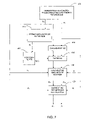
- FIG. 7 contains a top-level flow diagram which illustrates the logical flow of one embodiment of adaptive scatter correction for multi-energy projection data in accordance with the teachings of the present disclosure.
- FIG. 8 illustrates an example of a detector array of the present disclosure.
- FIG. 9 shows a graphical illustration of high energy projections of an Aluminum cylinder for one row of a detector array, and intermediate results for estimating the low-pass filter size.
- FIG. 10 shows a graphical illustration of high energy projection of a Nylon cylinder for one row of a detector array, and intermediate results for estimating the low-pass filter size.
- an adaptive scatter correction algorithm for multi-energy projections is provided to better estimate amounts of scatter and correct for them, resulting in improved quality of Z (effective atomic number) images.
- the algorithm does not use scatter detectors to measure the amounts of scatter, but instead, estimates the amounts of scatter from the input projection data.
- the algorithm preferably takes the spatial correlation of the scattering process into account, and adaptively uses attenuations and shapes of scanned objects to estimate the amounts of scatter, thereafter correcting for them.
- FIG. 6 illustrates the signal and data flow of the scanner system for explosive detection for the checked baggage for an airport of the present disclosure.
- Scanner 120 is typically similar to the one shown in FIG. 1 and has an X-ray source capable of producing a fan beam at two distinct energy levels (i.e., dual energy).
- DAS 134 gathers signals generated by detector array 130 at discrete angular positions of the rotating platform 124 , and passes the signals to the pre-processing unit 206 .
- the pre-processing unit 206 re-sorts the data it receives from DAS 134 in order to optimize the sequence for the subsequent mathematical processing.
- the pre-processing unit 206 also corrects the data from DAS 134 for detector temperature, intensity of the primary beam, gain and offset, and other deterministic error factors associated with each detector of the detector array. Finally, the pre-processing unit 206 extracts data P H corresponding to high-energy views and routes it to a high energy path 208 , and routes the data P L corresponding to low-energy views to a low energy path 210 .
- the adaptive scatter correction module 215 receives the projection data on the high energy path 208 and the low energy path 210 and performs scatter correction to produce the scatter corrected high energy projections P′ H 209 and scattered corrected low energy projections P′ L 211 .
- the dual energy decomposition computer 212 receives the scatter corrected high energy projections 209 and scattered corrected low energy projections 211 and performs a dual energy decomposition to produce photoelectric projections 216 .
- a first reconstruction computer 221 receives the stream of the photoelectric projection data 216 and generates a photoelectric image I p 225 .
- the second reconstruction computer 218 receives the stream of high energy projection data P H 208 and generates a CT image I H 226 . These two images 225 and 226 are processed in the post-processing unit 230 to yield a Z image I z .
- the unit 240 displays the high energy CT image I H 226 and the Z image I z 232 to operators, and the unit 238 uses the Z image 232 and the CT image 226 for automatic explosive detection.
- CT images are used to replace Compton images in computing Z images to reduce the computational cost as described the assignees' co-pending application “Method of and system for computing effective atomic number image in multi-energy computed tomography” by Zhengrong Ying, et. al. U.S. application Ser. No. 10/850,910, filed on May 21, 2004, incorporated herein by reference.
- an adaptive scatter correction algorithm for multi-energy projection data acquired by scanning a set of objects using at least two X-ray spectra is provided.
- the input projection data may include a set of high energy projections and a set of low energy projections.
- This embodiment is described with respect to a CT scanner with an x-ray source and detector configuration, such as that shown and described with respect to FIGS. 1 , 2 , and 3 .
- a low-pass filter of variable size is also provided for estimating the amounts of scatter for both sets of projections, where the size is determined adaptively depending on the input projection data.
- the present disclosure for adaptive scatter correction comprises:
- FIG. 7 contains the flow chart of a preferred embodiment of the method in accordance with one aspect of the present disclosure, and is used preferably to describe the details of the method.
- the scanner source generates a low energy spectrum and a high energy spectrum.
- the detector array containing a matrix of detectors receives the corresponding high energy and low energy x-ray intensities.
- FIG. 8 shows a useful pattern of a detector array 130 comprising of a matrix of detectors 12 of the present disclosure.
- c(0, . . ., S-1) the index of the column of detector array shown as the horizontal direction in FIG. 8 .
- I L (c) and I H (c) are the corresponding x-ray intensities that are detected when the object is scanned.
- I OL (c) and I OH (c) are the corresponding x-ray intensities that are detected in the absence of any object.
- P L (c) and P H (c) are the corresponding low and high energy projections that are measured by the scanner's detector at a given angle, given by:
- a one-dimensional odd-number-point long rectangular low-pass filter is provided at step 402 .
- the filter with the following form is preferably used,
- W is the filter size, and is estimated from the input projection data.
- the filter size is estimated using the high energy projections as described below.
- the high energy projections P H (c) are thresholded into binary projections B(c) as follows,
- the binary projections B(c) are then filtered using a rectangular window with a pre-defined size of W ini as follows,
- the filter size is calculated as follows from the maximum value of the filtered binary projections as follows,
- W ′ ⁇ ⁇ w ⁇ MW ini 2 ⁇ W ini + 1 + 1 2 ⁇
- ⁇ w pre-defined constant, and the value is experimentally determined.
- ⁇ w 1.4 yields satisfactory results in the assignee's scanner as described before.
- ⁇ x ⁇ is the maximum integer which is not greater than x.
- the calculated filter size W′ is clamped with a pre-defined value W min to yield the estimated filter size W for estimating amounts of scatter as follows,
- FIG. 9 and FIG. 10 show respectively examples of high energy projection data of an Aluminum cylinder and a Nylon cylinder for one row detectors of a detector array.
- the Aluminum cylinder and Nylon cylinder have different diameters and different projection data values.
- the estimated filter size W for the Nylon cylinder is 37, and is 12 for the Aluminum cylinder, indicating that the algorithm is adaptive to the size and attenuation of the scanned objects.
- item 700 is the high energy projections
- item 702 is P shape at value of 1.5
- item 710 is the binary projection B(c)
- item 720 is the filtered binary projection C(c).
- step 416 filtering is performed on the exponentiated projections using the low-pass filter h(n) with the estimated filter size W as follows,
- ⁇ H and ⁇ L are pre-defined constants, ⁇ L is preferably larger than ⁇ H due to the fact that the low energy projections have more scatter than the high energy projections.
- the amounts of scatter are subtracted from the input projections to yield the corrected projections.
- P′ H (c) P H ( c ) ⁇ P SH ( c )
- P′ L ( c ) P L ( c ) ⁇ P SL ( c )
Abstract
Description
- Estimating the size of the low-pass filter from the set of high energy projections,
- Computing amounts of scatter for both sets of projections using the low-pass filter of the estimated size
- Correcting both sets of projections with the computed amounts of scatter
where W is the filter size, and is estimated from the input projection data.
where Pshape is a pre-defined threshold, and its value is experimentally determined, for example, Pshape=1.5 yields satisfactory results in the assignee's scanner system as described before.
The pre-defined value of Wini is experimentally determined, for example, Wini=40 yields satisfactory results in the assignee's scanner system as described before. Note that zero-padding scheme is preferably used for the boundary conditions, i.e., C(c)=0, for c<0 and c≧S.
where σw is pre-defined constant, and the value is experimentally determined. For example, σw=1.4 yields satisfactory results in the assignee's scanner as described before. Note that └x┘ is the maximum integer which is not greater than x.
Note that the value of Wmin is experimentally determined, for example, Wmin=10 yields satisfactory results in the assignee's scanner system as described before.
Q H(c)=exp(P H(c)),
Q L(c)=exp(P L(c)),
Note that the border replication scheme is used to extend the projection data to its index limits, i.e.,
Q H(c)=Q H(0), and Q L(c)=Q L(0) for c<0,
Q H(c)=Q H(S−1), and Q L(c)=Q L(S−1) for c≧S
P SH(c)=−α H P H(c)F H(c)
P SL(c)=−α L P L(c)F L(c)
P′ H(c)=P H(c)−P SH(c)
P′ L(c)=P L(c)−P SL(c)
Claims (14)
Priority Applications (1)
| Application Number | Priority Date | Filing Date | Title |
|---|---|---|---|
| US10/853,942 US7136450B2 (en) | 2004-05-26 | 2004-05-26 | Method of and system for adaptive scatter correction in multi-energy computed tomography |
Applications Claiming Priority (1)
| Application Number | Priority Date | Filing Date | Title |
|---|---|---|---|
| US10/853,942 US7136450B2 (en) | 2004-05-26 | 2004-05-26 | Method of and system for adaptive scatter correction in multi-energy computed tomography |
Publications (2)
| Publication Number | Publication Date |
|---|---|
| US20050276373A1 US20050276373A1 (en) | 2005-12-15 |
| US7136450B2 true US7136450B2 (en) | 2006-11-14 |
Family
ID=35460511
Family Applications (1)
| Application Number | Title | Priority Date | Filing Date |
|---|---|---|---|
| US10/853,942 Expired - Fee Related US7136450B2 (en) | 2004-05-26 | 2004-05-26 | Method of and system for adaptive scatter correction in multi-energy computed tomography |
Country Status (1)
| Country | Link |
|---|---|
| US (1) | US7136450B2 (en) |
Cited By (30)
| Publication number | Priority date | Publication date | Assignee | Title |
|---|---|---|---|---|
| US20050201605A1 (en) * | 2004-03-11 | 2005-09-15 | Jianying Li | Methods and apparatus for CT smoothing to reduce artifacts |
| US20060198489A1 (en) * | 2005-03-01 | 2006-09-07 | Ge Medical Systems Global Technology Company, Llc | Scattering compensating method and scattering measuring method |
| US20080193002A1 (en) * | 2007-02-09 | 2008-08-14 | Zhengrong Ying | Method of and system for automatic object display of volumetric computed tomography images for fast on-screen threat resolution |
| US20090003515A1 (en) * | 2007-06-27 | 2009-01-01 | Ram Naidu | Method of and system for variable pitch computed tomography scanning for baggage screening |
| US20090304249A1 (en) * | 2008-06-06 | 2009-12-10 | General Electric Company | Material composition detection from effective atomic number computation |
| US7684538B2 (en) | 2003-04-25 | 2010-03-23 | Rapiscan Systems, Inc. | X-ray scanning system |
| US7724868B2 (en) | 2003-04-25 | 2010-05-25 | Rapiscan Systems, Inc. | X-ray monitoring |
| US20100189376A1 (en) * | 2009-01-29 | 2010-07-29 | Koninklijke Philips Electronics N.V. | Detection values correction apparatus |
| EP2309257A1 (en) | 2008-03-27 | 2011-04-13 | Analogic Corporation | Method of and system for three-dimensional workstation for security and medical applications |
| US7949101B2 (en) | 2005-12-16 | 2011-05-24 | Rapiscan Systems, Inc. | X-ray scanners and X-ray sources therefor |
| US8135110B2 (en) | 2005-12-16 | 2012-03-13 | Rapiscan Systems, Inc. | X-ray tomography inspection systems |
| US8223919B2 (en) | 2003-04-25 | 2012-07-17 | Rapiscan Systems, Inc. | X-ray tomographic inspection systems for the identification of specific target items |
| US8243876B2 (en) | 2003-04-25 | 2012-08-14 | Rapiscan Systems, Inc. | X-ray scanners |
| US8451974B2 (en) | 2003-04-25 | 2013-05-28 | Rapiscan Systems, Inc. | X-ray tomographic inspection system for the identification of specific target items |
| US20140169520A1 (en) * | 2012-12-19 | 2014-06-19 | Morpho Detection, Inc. | Systems and methods for dual energy imaging |
| US8804899B2 (en) | 2003-04-25 | 2014-08-12 | Rapiscan Systems, Inc. | Imaging, data acquisition, data transmission, and data distribution methods and systems for high data rate tomographic X-ray scanners |
| US8837669B2 (en) | 2003-04-25 | 2014-09-16 | Rapiscan Systems, Inc. | X-ray scanning system |
| US9052403B2 (en) | 2002-07-23 | 2015-06-09 | Rapiscan Systems, Inc. | Compact mobile cargo scanning system |
| US9113839B2 (en) | 2003-04-25 | 2015-08-25 | Rapiscon Systems, Inc. | X-ray inspection system and method |
| US9218933B2 (en) | 2011-06-09 | 2015-12-22 | Rapidscan Systems, Inc. | Low-dose radiographic imaging system |
| US9223049B2 (en) | 2002-07-23 | 2015-12-29 | Rapiscan Systems, Inc. | Cargo scanning system with boom structure |
| US9223050B2 (en) | 2005-04-15 | 2015-12-29 | Rapiscan Systems, Inc. | X-ray imaging system having improved mobility |
| US9223052B2 (en) | 2008-02-28 | 2015-12-29 | Rapiscan Systems, Inc. | Scanning systems |
| US9285498B2 (en) | 2003-06-20 | 2016-03-15 | Rapiscan Systems, Inc. | Relocatable X-ray imaging system and method for inspecting commercial vehicles and cargo containers |
| US9332624B2 (en) | 2008-05-20 | 2016-05-03 | Rapiscan Systems, Inc. | Gantry scanner systems |
| US9429530B2 (en) | 2008-02-28 | 2016-08-30 | Rapiscan Systems, Inc. | Scanning systems |
| US20170032547A1 (en) * | 2014-04-08 | 2017-02-02 | Siemens Healthcare Gmbh | Noise Reduction in Tomograms |
| US9791590B2 (en) | 2013-01-31 | 2017-10-17 | Rapiscan Systems, Inc. | Portable security inspection system |
| US11054534B1 (en) | 2020-04-24 | 2021-07-06 | Ronald Nutt | Time-resolved positron emission tomography encoder system for producing real-time, high resolution, three dimensional positron emission tomographic image without the necessity of performing image reconstruction |
| US11300695B2 (en) | 2020-04-24 | 2022-04-12 | Ronald Nutt | Time-resolved positron emission tomography encoder system for producing event-by-event, real-time, high resolution, three-dimensional positron emission tomographic image without the necessity of performing image reconstruction |
Families Citing this family (12)
| Publication number | Priority date | Publication date | Assignee | Title |
|---|---|---|---|---|
| US7539337B2 (en) * | 2005-07-18 | 2009-05-26 | Analogic Corporation | Method of and system for splitting compound objects in multi-energy computed tomography images |
| US7801348B2 (en) | 2005-07-18 | 2010-09-21 | Analogic Corporation | Method of and system for classifying objects using local distributions of multi-energy computed tomography images |
| US7283605B2 (en) * | 2006-01-14 | 2007-10-16 | General Electric Company | Methods and apparatus for scatter correction |
| DE102006046191B4 (en) * | 2006-09-29 | 2017-02-02 | Siemens Healthcare Gmbh | Stray radiation correction in radiography and computed tomography with area detectors |
| US8553959B2 (en) * | 2008-03-21 | 2013-10-08 | General Electric Company | Method and apparatus for correcting multi-modality imaging data |
| DE102009051635A1 (en) * | 2009-11-02 | 2011-05-05 | Siemens Aktiengesellschaft | Improved scatter correction on raw data in computed tomography |
| CN103900931B (en) * | 2012-12-26 | 2017-04-26 | 首都师范大学 | Multi-energy-spectrum CT imaging method and imaging system |
| KR102539407B1 (en) * | 2016-01-14 | 2023-06-01 | 프리스매틱 센서즈 에이비 | A MEASUREMENT CIRCUIT FOR AN X-RAY DETECTOR, AND A CORRESPONDING METHOD AND X-RAY IMAGING SYSTEM |
| WO2019035234A1 (en) * | 2017-08-18 | 2019-02-21 | 富士電機株式会社 | X-ray inspection system and x-ray inspection method |
| CN111096761B (en) * | 2018-10-29 | 2024-03-08 | 上海西门子医疗器械有限公司 | Method, device and related equipment for correcting scattering of wedge-shaped filter |
| CN110175957B (en) * | 2019-04-11 | 2021-03-09 | 清华大学 | Multi-energy CT-based material decomposition method |
| US11071506B1 (en) * | 2020-04-28 | 2021-07-27 | Wisconsin Alumni Research Foundation | X-ray imaging device providing enhanced spatial resolution by energy encoding |
Citations (30)
| Publication number | Priority date | Publication date | Assignee | Title |
|---|---|---|---|---|
| US4727562A (en) * | 1985-09-16 | 1988-02-23 | General Electric Company | Measurement of scatter in x-ray imaging |
| US4891829A (en) * | 1986-11-19 | 1990-01-02 | Exxon Research And Engineering Company | Method and apparatus for utilizing an electro-optic detector in a microtomography system |
| US5802134A (en) | 1997-04-09 | 1998-09-01 | Analogic Corporation | Nutating slice CT image reconstruction apparatus and method |
| US5901198A (en) | 1997-10-10 | 1999-05-04 | Analogic Corporation | Computed tomography scanning target detection using target surface normals |
| US5932874A (en) | 1997-10-10 | 1999-08-03 | Analogic Corporation | Measurement and control system for controlling system functions as a function of rotational parameters of a rotating device |
| US5937028A (en) | 1997-10-10 | 1999-08-10 | Analogic Corporation | Rotary energy shield for computed tomography scanner |
| US5949842A (en) | 1997-10-10 | 1999-09-07 | Analogic Corporation | Air calibration scan for computed tomography scanner with obstructing objects |
| US5970113A (en) | 1997-10-10 | 1999-10-19 | Analogic Corporation | Computed tomography scanning apparatus and method with temperature compensation for dark current offsets |
| US5982843A (en) | 1997-10-10 | 1999-11-09 | Analogic Corporation | Closed loop air conditioning system for a computed tomography scanner |
| US5982844A (en) | 1997-10-10 | 1999-11-09 | Analogic Corporation | Computed tomography scanner drive system and bearing |
| US6025143A (en) | 1988-10-11 | 2000-02-15 | Institut Pasteur | Antibodies directed against peptides derived from the SMR1 polypeptide |
| US6026171A (en) | 1998-02-11 | 2000-02-15 | Analogic Corporation | Apparatus and method for detection of liquids in computed tomography data |
| US6035014A (en) | 1998-02-11 | 2000-03-07 | Analogic Corporation | Multiple-stage apparatus and method for detecting objects in computed tomography data |
| US6067366A (en) | 1998-02-11 | 2000-05-23 | Analogic Corporation | Apparatus and method for detecting objects in computed tomography data using erosion and dilation of objects |
| US6075871A (en) | 1998-02-11 | 2000-06-13 | Analogic Corporation | Apparatus and method for eroding objects in computed tomography data |
| US6076400A (en) | 1998-02-11 | 2000-06-20 | Analogic Corporation | Apparatus and method for classifying objects in computed tomography data using density dependent mass thresholds |
| US6078642A (en) | 1998-02-11 | 2000-06-20 | Analogice Corporation | Apparatus and method for density discrimination of objects in computed tomography data using multiple density ranges |
| US6091795A (en) | 1997-10-10 | 2000-07-18 | Analogic Corporation | Area detector array for computer tomography scanning system |
| US6108396A (en) | 1998-02-11 | 2000-08-22 | Analogic Corporation | Apparatus and method for correcting object density in computed tomography data |
| US6111974A (en) | 1998-02-11 | 2000-08-29 | Analogic Corporation | Apparatus and method for detecting sheet objects in computed tomography data |
| US6128365A (en) | 1998-02-11 | 2000-10-03 | Analogic Corporation | Apparatus and method for combining related objects in computed tomography data |
| US6195444B1 (en) | 1999-01-12 | 2001-02-27 | Analogic Corporation | Apparatus and method for detecting concealed objects in computed tomography data |
| US6196715B1 (en) * | 1959-04-28 | 2001-03-06 | Kabushiki Kaisha Toshiba | X-ray diagnostic system preferable to two dimensional x-ray detection |
| US6256404B1 (en) | 1997-10-10 | 2001-07-03 | Analogic Corporation | Computed tomography scanning apparatus and method using adaptive reconstruction window |
| US6272230B1 (en) | 1998-02-11 | 2001-08-07 | Analogic Corporation | Apparatus and method for optimizing detection of objects in computed tomography data |
| US6345113B1 (en) | 1999-01-12 | 2002-02-05 | Analogic Corporation | Apparatus and method for processing object data in computed tomography data using object projections |
| US6490476B1 (en) * | 1999-10-14 | 2002-12-03 | Cti Pet Systems, Inc. | Combined PET and X-ray CT tomograph and method for using same |
| US6618466B1 (en) * | 2002-02-21 | 2003-09-09 | University Of Rochester | Apparatus and method for x-ray scatter reduction and correction for fan beam CT and cone beam volume CT |
| US6687326B1 (en) | 2001-04-11 | 2004-02-03 | Analogic Corporation | Method of and system for correcting scatter in a computed tomography scanner |
| US6721387B1 (en) | 2001-06-13 | 2004-04-13 | Analogic Corporation | Method of and system for reducing metal artifacts in images generated by x-ray scanning devices |
-
2004
- 2004-05-26 US US10/853,942 patent/US7136450B2/en not_active Expired - Fee Related
Patent Citations (33)
| Publication number | Priority date | Publication date | Assignee | Title |
|---|---|---|---|---|
| US6196715B1 (en) * | 1959-04-28 | 2001-03-06 | Kabushiki Kaisha Toshiba | X-ray diagnostic system preferable to two dimensional x-ray detection |
| US4727562A (en) * | 1985-09-16 | 1988-02-23 | General Electric Company | Measurement of scatter in x-ray imaging |
| US4891829A (en) * | 1986-11-19 | 1990-01-02 | Exxon Research And Engineering Company | Method and apparatus for utilizing an electro-optic detector in a microtomography system |
| US6025143A (en) | 1988-10-11 | 2000-02-15 | Institut Pasteur | Antibodies directed against peptides derived from the SMR1 polypeptide |
| US5802134A (en) | 1997-04-09 | 1998-09-01 | Analogic Corporation | Nutating slice CT image reconstruction apparatus and method |
| US5881122A (en) | 1997-04-09 | 1999-03-09 | Analogic Corporation | Computed tomography scanning apparatus and method for generating parallel projections using non-parallel slice data |
| US5887047A (en) | 1997-04-09 | 1999-03-23 | Analogic Corporation | Parallel processing architecture for computed tomography scanning system using non-parallel slices |
| US5909477A (en) | 1997-04-09 | 1999-06-01 | Analogic Corporation | Computed tomography scanning target detection using non-parallel slices |
| US5937028A (en) | 1997-10-10 | 1999-08-10 | Analogic Corporation | Rotary energy shield for computed tomography scanner |
| US5949842A (en) | 1997-10-10 | 1999-09-07 | Analogic Corporation | Air calibration scan for computed tomography scanner with obstructing objects |
| US5970113A (en) | 1997-10-10 | 1999-10-19 | Analogic Corporation | Computed tomography scanning apparatus and method with temperature compensation for dark current offsets |
| US5982843A (en) | 1997-10-10 | 1999-11-09 | Analogic Corporation | Closed loop air conditioning system for a computed tomography scanner |
| US5982844A (en) | 1997-10-10 | 1999-11-09 | Analogic Corporation | Computed tomography scanner drive system and bearing |
| US6091795A (en) | 1997-10-10 | 2000-07-18 | Analogic Corporation | Area detector array for computer tomography scanning system |
| US6256404B1 (en) | 1997-10-10 | 2001-07-03 | Analogic Corporation | Computed tomography scanning apparatus and method using adaptive reconstruction window |
| US5932874A (en) | 1997-10-10 | 1999-08-03 | Analogic Corporation | Measurement and control system for controlling system functions as a function of rotational parameters of a rotating device |
| US5901198A (en) | 1997-10-10 | 1999-05-04 | Analogic Corporation | Computed tomography scanning target detection using target surface normals |
| US6067366A (en) | 1998-02-11 | 2000-05-23 | Analogic Corporation | Apparatus and method for detecting objects in computed tomography data using erosion and dilation of objects |
| US6272230B1 (en) | 1998-02-11 | 2001-08-07 | Analogic Corporation | Apparatus and method for optimizing detection of objects in computed tomography data |
| US6078642A (en) | 1998-02-11 | 2000-06-20 | Analogice Corporation | Apparatus and method for density discrimination of objects in computed tomography data using multiple density ranges |
| US6075871A (en) | 1998-02-11 | 2000-06-13 | Analogic Corporation | Apparatus and method for eroding objects in computed tomography data |
| US6108396A (en) | 1998-02-11 | 2000-08-22 | Analogic Corporation | Apparatus and method for correcting object density in computed tomography data |
| US6111974A (en) | 1998-02-11 | 2000-08-29 | Analogic Corporation | Apparatus and method for detecting sheet objects in computed tomography data |
| US6128365A (en) | 1998-02-11 | 2000-10-03 | Analogic Corporation | Apparatus and method for combining related objects in computed tomography data |
| US6076400A (en) | 1998-02-11 | 2000-06-20 | Analogic Corporation | Apparatus and method for classifying objects in computed tomography data using density dependent mass thresholds |
| US6035014A (en) | 1998-02-11 | 2000-03-07 | Analogic Corporation | Multiple-stage apparatus and method for detecting objects in computed tomography data |
| US6026171A (en) | 1998-02-11 | 2000-02-15 | Analogic Corporation | Apparatus and method for detection of liquids in computed tomography data |
| US6195444B1 (en) | 1999-01-12 | 2001-02-27 | Analogic Corporation | Apparatus and method for detecting concealed objects in computed tomography data |
| US6345113B1 (en) | 1999-01-12 | 2002-02-05 | Analogic Corporation | Apparatus and method for processing object data in computed tomography data using object projections |
| US6490476B1 (en) * | 1999-10-14 | 2002-12-03 | Cti Pet Systems, Inc. | Combined PET and X-ray CT tomograph and method for using same |
| US6687326B1 (en) | 2001-04-11 | 2004-02-03 | Analogic Corporation | Method of and system for correcting scatter in a computed tomography scanner |
| US6721387B1 (en) | 2001-06-13 | 2004-04-13 | Analogic Corporation | Method of and system for reducing metal artifacts in images generated by x-ray scanning devices |
| US6618466B1 (en) * | 2002-02-21 | 2003-09-09 | University Of Rochester | Apparatus and method for x-ray scatter reduction and correction for fan beam CT and cone beam volume CT |
Cited By (62)
| Publication number | Priority date | Publication date | Assignee | Title |
|---|---|---|---|---|
| US10670769B2 (en) | 2002-07-23 | 2020-06-02 | Rapiscan Systems, Inc. | Compact mobile cargo scanning system |
| US9052403B2 (en) | 2002-07-23 | 2015-06-09 | Rapiscan Systems, Inc. | Compact mobile cargo scanning system |
| US9223049B2 (en) | 2002-07-23 | 2015-12-29 | Rapiscan Systems, Inc. | Cargo scanning system with boom structure |
| US10007019B2 (en) | 2002-07-23 | 2018-06-26 | Rapiscan Systems, Inc. | Compact mobile cargo scanning system |
| US9747705B2 (en) | 2003-04-25 | 2017-08-29 | Rapiscan Systems, Inc. | Imaging, data acquisition, data transmission, and data distribution methods and systems for high data rate tomographic X-ray scanners |
| US9618648B2 (en) | 2003-04-25 | 2017-04-11 | Rapiscan Systems, Inc. | X-ray scanners |
| US7684538B2 (en) | 2003-04-25 | 2010-03-23 | Rapiscan Systems, Inc. | X-ray scanning system |
| US10591424B2 (en) | 2003-04-25 | 2020-03-17 | Rapiscan Systems, Inc. | X-ray tomographic inspection systems for the identification of specific target items |
| US7724868B2 (en) | 2003-04-25 | 2010-05-25 | Rapiscan Systems, Inc. | X-ray monitoring |
| US10175381B2 (en) | 2003-04-25 | 2019-01-08 | Rapiscan Systems, Inc. | X-ray scanners having source points with less than a predefined variation in brightness |
| US11796711B2 (en) | 2003-04-25 | 2023-10-24 | Rapiscan Systems, Inc. | Modular CT scanning system |
| US7929663B2 (en) | 2003-04-25 | 2011-04-19 | Rapiscan Systems, Inc. | X-ray monitoring |
| US9183647B2 (en) | 2003-04-25 | 2015-11-10 | Rapiscan Systems, Inc. | Imaging, data acquisition, data transmission, and data distribution methods and systems for high data rate tomographic X-ray scanners |
| US9675306B2 (en) | 2003-04-25 | 2017-06-13 | Rapiscan Systems, Inc. | X-ray scanning system |
| US9113839B2 (en) | 2003-04-25 | 2015-08-25 | Rapiscon Systems, Inc. | X-ray inspection system and method |
| US10901112B2 (en) | 2003-04-25 | 2021-01-26 | Rapiscan Systems, Inc. | X-ray scanning system with stationary x-ray sources |
| US8223919B2 (en) | 2003-04-25 | 2012-07-17 | Rapiscan Systems, Inc. | X-ray tomographic inspection systems for the identification of specific target items |
| US8243876B2 (en) | 2003-04-25 | 2012-08-14 | Rapiscan Systems, Inc. | X-ray scanners |
| US8451974B2 (en) | 2003-04-25 | 2013-05-28 | Rapiscan Systems, Inc. | X-ray tomographic inspection system for the identification of specific target items |
| US9442082B2 (en) | 2003-04-25 | 2016-09-13 | Rapiscan Systems, Inc. | X-ray inspection system and method |
| US8885794B2 (en) | 2003-04-25 | 2014-11-11 | Rapiscan Systems, Inc. | X-ray tomographic inspection system for the identification of specific target items |
| US9020095B2 (en) | 2003-04-25 | 2015-04-28 | Rapiscan Systems, Inc. | X-ray scanners |
| US8804899B2 (en) | 2003-04-25 | 2014-08-12 | Rapiscan Systems, Inc. | Imaging, data acquisition, data transmission, and data distribution methods and systems for high data rate tomographic X-ray scanners |
| US8837669B2 (en) | 2003-04-25 | 2014-09-16 | Rapiscan Systems, Inc. | X-ray scanning system |
| US9285498B2 (en) | 2003-06-20 | 2016-03-15 | Rapiscan Systems, Inc. | Relocatable X-ray imaging system and method for inspecting commercial vehicles and cargo containers |
| US20050201605A1 (en) * | 2004-03-11 | 2005-09-15 | Jianying Li | Methods and apparatus for CT smoothing to reduce artifacts |
| US7336759B2 (en) * | 2005-03-01 | 2008-02-26 | Ge Medical Systems Global Technology Company, Llc | Scattering compensating method and scattering measuring method |
| US20060198489A1 (en) * | 2005-03-01 | 2006-09-07 | Ge Medical Systems Global Technology Company, Llc | Scattering compensating method and scattering measuring method |
| US9223050B2 (en) | 2005-04-15 | 2015-12-29 | Rapiscan Systems, Inc. | X-ray imaging system having improved mobility |
| US8135110B2 (en) | 2005-12-16 | 2012-03-13 | Rapiscan Systems, Inc. | X-ray tomography inspection systems |
| US10976271B2 (en) | 2005-12-16 | 2021-04-13 | Rapiscan Systems, Inc. | Stationary tomographic X-ray imaging systems for automatically sorting objects based on generated tomographic images |
| US9048061B2 (en) | 2005-12-16 | 2015-06-02 | Rapiscan Systems, Inc. | X-ray scanners and X-ray sources therefor |
| US8958526B2 (en) | 2005-12-16 | 2015-02-17 | Rapiscan Systems, Inc. | Data collection, processing and storage systems for X-ray tomographic images |
| US7949101B2 (en) | 2005-12-16 | 2011-05-24 | Rapiscan Systems, Inc. | X-ray scanners and X-ray sources therefor |
| US10295483B2 (en) | 2005-12-16 | 2019-05-21 | Rapiscan Systems, Inc. | Data collection, processing and storage systems for X-ray tomographic images |
| US8625735B2 (en) | 2005-12-16 | 2014-01-07 | Rapiscan Systems, Inc. | X-ray scanners and X-ray sources therefor |
| US9638646B2 (en) | 2005-12-16 | 2017-05-02 | Rapiscan Systems, Inc. | X-ray scanners and X-ray sources therefor |
| US8009883B2 (en) | 2007-02-09 | 2011-08-30 | Analogic Corporation | Method of and system for automatic object display of volumetric computed tomography images for fast on-screen threat resolution |
| US20080193002A1 (en) * | 2007-02-09 | 2008-08-14 | Zhengrong Ying | Method of and system for automatic object display of volumetric computed tomography images for fast on-screen threat resolution |
| US20090003515A1 (en) * | 2007-06-27 | 2009-01-01 | Ram Naidu | Method of and system for variable pitch computed tomography scanning for baggage screening |
| US7724866B2 (en) | 2007-06-27 | 2010-05-25 | Analogic Corporation | Method of and system for variable pitch computed tomography scanning for baggage screening |
| US9429530B2 (en) | 2008-02-28 | 2016-08-30 | Rapiscan Systems, Inc. | Scanning systems |
| US11275194B2 (en) | 2008-02-28 | 2022-03-15 | Rapiscan Systems, Inc. | Scanning systems |
| US9223052B2 (en) | 2008-02-28 | 2015-12-29 | Rapiscan Systems, Inc. | Scanning systems |
| US11768313B2 (en) | 2008-02-28 | 2023-09-26 | Rapiscan Systems, Inc. | Multi-scanner networked systems for performing material discrimination processes on scanned objects |
| US10585207B2 (en) | 2008-02-28 | 2020-03-10 | Rapiscan Systems, Inc. | Scanning systems |
| EP2309257A1 (en) | 2008-03-27 | 2011-04-13 | Analogic Corporation | Method of and system for three-dimensional workstation for security and medical applications |
| US10098214B2 (en) | 2008-05-20 | 2018-10-09 | Rapiscan Systems, Inc. | Detector support structures for gantry scanner systems |
| US9332624B2 (en) | 2008-05-20 | 2016-05-03 | Rapiscan Systems, Inc. | Gantry scanner systems |
| US8218837B2 (en) | 2008-06-06 | 2012-07-10 | General Electric Company | Material composition detection from effective atomic number computation |
| US20090304249A1 (en) * | 2008-06-06 | 2009-12-10 | General Electric Company | Material composition detection from effective atomic number computation |
| US8488902B2 (en) | 2009-01-29 | 2013-07-16 | Koninklijke Philips Electronics N.V. | Detection values correction apparatus |
| US20100189376A1 (en) * | 2009-01-29 | 2010-07-29 | Koninklijke Philips Electronics N.V. | Detection values correction apparatus |
| US9218933B2 (en) | 2011-06-09 | 2015-12-22 | Rapidscan Systems, Inc. | Low-dose radiographic imaging system |
| US20140169520A1 (en) * | 2012-12-19 | 2014-06-19 | Morpho Detection, Inc. | Systems and methods for dual energy imaging |
| US9791590B2 (en) | 2013-01-31 | 2017-10-17 | Rapiscan Systems, Inc. | Portable security inspection system |
| US11550077B2 (en) | 2013-01-31 | 2023-01-10 | Rapiscan Systems, Inc. | Portable vehicle inspection portal with accompanying workstation |
| US10317566B2 (en) | 2013-01-31 | 2019-06-11 | Rapiscan Systems, Inc. | Portable security inspection system |
| US20170032547A1 (en) * | 2014-04-08 | 2017-02-02 | Siemens Healthcare Gmbh | Noise Reduction in Tomograms |
| US10282872B2 (en) * | 2014-04-08 | 2019-05-07 | Siemens Healthcare Gmbh | Noise reduction in tomograms |
| US11054534B1 (en) | 2020-04-24 | 2021-07-06 | Ronald Nutt | Time-resolved positron emission tomography encoder system for producing real-time, high resolution, three dimensional positron emission tomographic image without the necessity of performing image reconstruction |
| US11300695B2 (en) | 2020-04-24 | 2022-04-12 | Ronald Nutt | Time-resolved positron emission tomography encoder system for producing event-by-event, real-time, high resolution, three-dimensional positron emission tomographic image without the necessity of performing image reconstruction |
Also Published As
| Publication number | Publication date |
|---|---|
| US20050276373A1 (en) | 2005-12-15 |
Similar Documents
| Publication | Publication Date | Title |
|---|---|---|
| US7136450B2 (en) | Method of and system for adaptive scatter correction in multi-energy computed tomography | |
| US7190757B2 (en) | Method of and system for computing effective atomic number images in multi-energy computed tomography | |
| US7224763B2 (en) | Method of and system for X-ray spectral correction in multi-energy computed tomography | |
| US7136451B2 (en) | Method of and system for stabilizing high voltage power supply voltages in multi-energy computed tomography | |
| US7327853B2 (en) | Method of and system for extracting 3D bag images from continuously reconstructed 2D image slices in computed tomography | |
| US6256404B1 (en) | Computed tomography scanning apparatus and method using adaptive reconstruction window | |
| US7197172B1 (en) | Decomposition of multi-energy scan projections using multi-step fitting | |
| US7801348B2 (en) | Method of and system for classifying objects using local distributions of multi-energy computed tomography images | |
| US7539337B2 (en) | Method of and system for splitting compound objects in multi-energy computed tomography images | |
| US5949842A (en) | Air calibration scan for computed tomography scanner with obstructing objects | |
| US7302083B2 (en) | Method of and system for sharp object detection using computed tomography images | |
| US5901198A (en) | Computed tomography scanning target detection using target surface normals | |
| US5970113A (en) | Computed tomography scanning apparatus and method with temperature compensation for dark current offsets | |
| US6418189B1 (en) | Explosive material detection apparatus and method using dual energy information of a scan | |
| US6345113B1 (en) | Apparatus and method for processing object data in computed tomography data using object projections | |
| US7453974B2 (en) | Beam-hardening and attenuation correction for coherent-scatter CT | |
| US7474786B2 (en) | Method of and system for classifying objects using histogram segment features of multi-energy computed tomography images | |
| US7623616B2 (en) | Computer tomography apparatus and method for examining an object of interest | |
| US7692650B2 (en) | Method of and system for 3D display of multi-energy computed tomography images | |
| US7519143B2 (en) | Method and system for generating a scatter corrected X-ray image | |
| US10595808B2 (en) | System and method of computed tomography signal restoration via noise reduction | |
| EP1875276B1 (en) | Energy distribution reconstruction in ct | |
| US20090169081A1 (en) | Image based computed tomography number and volume corrections for thin objects in computed tomography systems | |
| US8009883B2 (en) | Method of and system for automatic object display of volumetric computed tomography images for fast on-screen threat resolution | |
| US7415147B2 (en) | Method of and system for destreaking the photoelectric image in multi-energy computed tomography |
Legal Events
| Date | Code | Title | Description |
|---|---|---|---|
| AS | Assignment |
Owner name: ANALOGIC CORPORATION, MASSACHUSETTS Free format text: ASSIGNMENT OF ASSIGNORS INTEREST;ASSIGNORS:YING, ZHENGRONG;NAIDU, RAM;SIMANOVSKY, SERGEY;AND OTHERS;REEL/FRAME:015916/0733 Effective date: 20040930 |
|
| FPAY | Fee payment |
Year of fee payment: 4 |
|
| FPAY | Fee payment |
Year of fee payment: 8 |
|
| AS | Assignment |
Owner name: MIDCAP FINANCIAL TRUST, MARYLAND Free format text: SECURITY INTEREST;ASSIGNORS:ANALOGIC CORPORATION;SOUND TECHNOLOGY, INC.;REEL/FRAME:046414/0277 Effective date: 20180622 |
|
| FEPP | Fee payment procedure |
Free format text: MAINTENANCE FEE REMINDER MAILED (ORIGINAL EVENT CODE: REM.) |
|
| LAPS | Lapse for failure to pay maintenance fees |
Free format text: PATENT EXPIRED FOR FAILURE TO PAY MAINTENANCE FEES (ORIGINAL EVENT CODE: EXP.); ENTITY STATUS OF PATENT OWNER: LARGE ENTITY |
|
| STCH | Information on status: patent discontinuation |
Free format text: PATENT EXPIRED DUE TO NONPAYMENT OF MAINTENANCE FEES UNDER 37 CFR 1.362 |
|
| FP | Lapsed due to failure to pay maintenance fee |
Effective date: 20181114 |
|
| AS | Assignment |
Owner name: ANALOGIC CORPORATION, MASSACHUSETTS Free format text: RELEASE BY SECURED PARTY;ASSIGNOR:MIDCAP FINANCIAL TRUST;REEL/FRAME:064917/0544 Effective date: 20230914 |