US7134777B2 - Surface lighting device with closed oblique reflector - Google Patents
Surface lighting device with closed oblique reflector Download PDFInfo
- Publication number
- US7134777B2 US7134777B2 US10/807,211 US80721104A US7134777B2 US 7134777 B2 US7134777 B2 US 7134777B2 US 80721104 A US80721104 A US 80721104A US 7134777 B2 US7134777 B2 US 7134777B2
- Authority
- US
- United States
- Prior art keywords
- light
- lighting device
- guide plate
- reflector
- incident surface
- Prior art date
- Legal status (The legal status is an assumption and is not a legal conclusion. Google has not performed a legal analysis and makes no representation as to the accuracy of the status listed.)
- Expired - Fee Related, expires
Links
Images


Classifications
-
- G—PHYSICS
- G02—OPTICS
- G02B—OPTICAL ELEMENTS, SYSTEMS OR APPARATUS
- G02B6/00—Light guides; Structural details of arrangements comprising light guides and other optical elements, e.g. couplings
- G02B6/0001—Light guides; Structural details of arrangements comprising light guides and other optical elements, e.g. couplings specially adapted for lighting devices or systems
- G02B6/0011—Light guides; Structural details of arrangements comprising light guides and other optical elements, e.g. couplings specially adapted for lighting devices or systems the light guides being planar or of plate-like form
- G02B6/0013—Means for improving the coupling-in of light from the light source into the light guide
- G02B6/0023—Means for improving the coupling-in of light from the light source into the light guide provided by one optical element, or plurality thereof, placed between the light guide and the light source, or around the light source
- G02B6/0028—Light guide, e.g. taper
-
- G—PHYSICS
- G02—OPTICS
- G02B—OPTICAL ELEMENTS, SYSTEMS OR APPARATUS
- G02B6/00—Light guides; Structural details of arrangements comprising light guides and other optical elements, e.g. couplings
- G02B6/0001—Light guides; Structural details of arrangements comprising light guides and other optical elements, e.g. couplings specially adapted for lighting devices or systems
- G02B6/0011—Light guides; Structural details of arrangements comprising light guides and other optical elements, e.g. couplings specially adapted for lighting devices or systems the light guides being planar or of plate-like form
- G02B6/0033—Means for improving the coupling-out of light from the light guide
- G02B6/0035—Means for improving the coupling-out of light from the light guide provided on the surface of the light guide or in the bulk of it
- G02B6/0038—Linear indentations or grooves, e.g. arc-shaped grooves or meandering grooves, extending over the full length or width of the light guide
-
- G—PHYSICS
- G02—OPTICS
- G02B—OPTICAL ELEMENTS, SYSTEMS OR APPARATUS
- G02B6/00—Light guides; Structural details of arrangements comprising light guides and other optical elements, e.g. couplings
- G02B6/0001—Light guides; Structural details of arrangements comprising light guides and other optical elements, e.g. couplings specially adapted for lighting devices or systems
- G02B6/0011—Light guides; Structural details of arrangements comprising light guides and other optical elements, e.g. couplings specially adapted for lighting devices or systems the light guides being planar or of plate-like form
- G02B6/0033—Means for improving the coupling-out of light from the light guide
- G02B6/0035—Means for improving the coupling-out of light from the light guide provided on the surface of the light guide or in the bulk of it
- G02B6/0045—Means for improving the coupling-out of light from the light guide provided on the surface of the light guide or in the bulk of it by shaping at least a portion of the light guide
- G02B6/0046—Tapered light guide, e.g. wedge-shaped light guide
-
- G—PHYSICS
- G02—OPTICS
- G02B—OPTICAL ELEMENTS, SYSTEMS OR APPARATUS
- G02B6/00—Light guides; Structural details of arrangements comprising light guides and other optical elements, e.g. couplings
- G02B6/0001—Light guides; Structural details of arrangements comprising light guides and other optical elements, e.g. couplings specially adapted for lighting devices or systems
- G02B6/0011—Light guides; Structural details of arrangements comprising light guides and other optical elements, e.g. couplings specially adapted for lighting devices or systems the light guides being planar or of plate-like form
- G02B6/0033—Means for improving the coupling-out of light from the light guide
- G02B6/005—Means for improving the coupling-out of light from the light guide provided by one optical element, or plurality thereof, placed on the light output side of the light guide
- G02B6/0053—Prismatic sheet or layer; Brightness enhancement element, sheet or layer
Definitions
- the present invention relates to a surface lighting device, and particularly to a surface lighting device for a liquid crystal display (LCD) or similar apparatus.
- LCD liquid crystal display
- a typical LCD device comprises a liquid crystal display panel, and a surface lighting device mounted under the liquid crystal display panel for supplying light beams thereto.
- the surface lighting device mainly comprises one or more light sources for emitting light beams, and a light guide plate.
- the light guide plate receives the emitted light beams via a light incident surface thereof, and emits the light beams via a light output surface thereof in order to uniformly illuminate the liquid crystal display panel.
- a linear source such as a cold cathode fluorescent lamp (CCFL)
- a point light source such as a light emitting diode (LED).
- LEDs used as light sources emit light beams having a divergent angle in the range from 30° to 130°.
- a light guide plate using LEDs as light sources generally yields a plurality of dark areas between adjacent LEDs.
- a surface lighting device includes a stick light guide body 16 mounted between two LEDs 20 a , 20 b for transferring light beams emitting from the LEDs 20 a , 20 b into a light guide plate 12 .
- the stick light guide body 16 is parallel to a light incident surface of the light guide plate 12 , and a length of the stick light guide body 16 approximately coincides with a length of the light incident surface.
- This configuration has the LEDs 20 a , 20 b cooperating with the stick light guide body 16 to provide light beams. That is, the combination functions as a linear light source to provide uniform light beams, and does not cause dark areas.
- one stick light guide body 16 needs two LEDs cooperating therewith, which increases costs.
- a light emitting surface E 1 of the LED 20 a is positioned outside the light stick guide body 16 , light leakage therebetween occurs. That is, the stick light guide body 16 cannot completely utilize the light beams emitted from LEDs 20 a , 20 b .
- the LEDs 20 a , 20 b and the stick light guide body 16 are provided at one side of the light guide plate 12 only. It is therefore relatively difficult for the surface lighting device to produce uniform emitting light.
- An object of the present invention is to provide a surface lighting device using only one LED as a light source.
- Another object of the present invention is to provide a surface lighting device capable of improving utilization of light beams emitted from an LED thereof.
- a further object of the present invention is to provide a surface lighting device which provides enhanced uniform illumination and brightness.
- a surface lighting device in accordance with the present invention includes a light guide plate, a point light source, and a light reflector substantially juxtaposed with the light guide plate.
- the light guide plate has a light incident surface.
- the point light source is located between one end of the light reflector and the light incident surface.
- the light reflector comprises a reflecting portion obliquely opposite to the light incident surface.
- the reflecting portion is adapted to receive light beams emitted from the point light source, and reflect the received light into the light incident surface of the light guide plate.
- Various configurations of the light reflector can be adopted to achieve this purpose. Because the light reflector has the oblique reflecting portion, more received light can be reflected away from its original transmitting path to provide more reflectivity.
- the point light source is positioned inside the light reflector, all the light emitted from the point light source transmits in a close space of the light reflector.
- a pair of opposite point light sources with corresponding light reflectors is utilized.
- FIG. 1 is an isometric view of a first surface lighting device according to the present invention
- FIG. 2 is a schematic cross-sectional view taken along line II—II of FIG. 1 ;
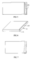
- FIGS. 3–7 are respective schematic cross-sectional views and an isometric view, showing various alternative embodiments of a light reflector of the surface lighting device of FIG. 1 and the surface lighting device itself;
- FIG. 8 is an isometric view of a second surface lighting device according to the present invention.
- FIG. 9 is a schematic cross-sectional view taken along line IX—IX of FIG. 8 ;
- FIGS. 10–11 are respective isometric and schematic cross-sectional views showing an alternative embodiment of light reflectors of the surface lighting device of FIG. 8 .
- a first surface lighting device 1 in accordance with the present invention is used to illuminate a liquid crystal display panel.
- the surface lighting device 1 comprises a light guide plate 11 , a brightness enhancement film 12 , a light reflector 13 , and an LED 14 for providing light beams.
- the light guide plate 11 is a rectangular slab of transparent material such as acrylic resin, polycarbonate resin, polyvinyl chloride, or glass.
- the light guide plate 11 comprises a light incident surface 111 , a light output surface (not labeled) adjoining the light incident surface 111 , and a bottom surface (not labeled) opposite to the light output surface.
- the light output surface and/or the bottom surface of the light guide plate 11 can be formed with a dot-pattern of light diffusers (not shown) or with V-cut grooves (not shown), for scattering incident light and improving a brightness and uniformity of the light guide plate 11 .
- the brightness enhancement film 12 is coated on the light incident surface 111 of the light guide plate 11 for improving a brightness of the light guide plate 1 .
- a plurality of V-cut grooves (not shown) can be formed in the light incident surface 111 instead of using the brightness enhancement film 12 , for improving the brightness of the light guide plate 11 .
- the light reflector 13 is substantially juxtaposed with the light guide plate 11 .
- the light reflector 13 comprises a sidewall 131 , and a planar top wall (not labeled) and a planar bottom wall (not labeled) adjoining the sidewall 131 .
- the sidewall 131 is obliquely opposite to the light incident surface 111 . That is, the sidewall 131 has a fixed end (not labeled) connecting with the light incident surface 111 , and an opposite free end (not labeled) spaced apart from the light incident surface 111 .
- the sidewall 131 further includes a dot-pattern (not shown) formed thereon or a plurality of V-cut grooves (not shown) formed therein, for improving a brightness and uniformity of reflected light.
- the LED 14 is disposed between the free end of the sidewall 131 and the brightness enhancement film 12 .
- the LED 14 is fixed on a mount portion 143 , and a light emitting surface 141 of the LED 14 is located inside the light reflector 13 .
- the light reflector 13 , the light incident surface 111 and the mount portion 143 coupled together define a closed space 133 therebetween.
- the space 133 receives light beams emitted from the LED 14 , and the light beams are reflected into the light guide plate 11 .
- FIGS. 3–7 show alternative embodiments of the surface lighting device 1 . These embodiments are similar to the above-described first surface lighting device 1 , except than the sidewall 131 of the light reflector 13 has different shapes.
- the sidewall shown in FIG. 3 has an arcuate shape.
- the sidewall shown in FIG. 4 has a straight main portion and an arcuate end connecting with the light incident surface 111 .
- the sidewall shown in FIG. 5 is formed parallel to the light incident surface 111 of the light guide plate 11 , and has a plurality of prisms 136 formed on an inside thereof. The prisms 136 are arranged in a line opposite from the light incident surface 111 , and function as reflector portions.
- the sidewall 135 has an arch-shaped cross-section.
- a top edge of the sidewall 135 adjoins a top edge of the light incident surface 111
- a bottom edge of the sidewall 135 adjoins a bottom edge of the light incident surface 1111 .
- the sidewall shown in FIG. 7 is L-shaped.
- the light guide plate is trapezoidal, and a main portion of the sidewall is obliquely opposite to a light incident surface of the light guide plate.
- An overall configuration of the combined light guide plate and light reflector is rectangular.
- FIGS. 8 and 9 show a second surface lighting device 2 according to the present invention.
- the surface lighting device 2 comprises two LEDs at opposite sides thereof respectively, for providing enhanced uniform emitting light.
- the surface lighting device 4 has two light reflectors 23 , 25 arranged at opposite sides of a light guide plate 21 respectively, corresponding to the LEDs.
- the light reflectors 23 , 25 are arranged opposite to each other, such that the LEDs are diagonally opposite from each other.
- FIGS. 10–11 shows a third surface lighting device 3 .
- the surface lighting device 3 is similar to the surface lighting device 2 , except that two light reflectors are arranged symmetrically opposite to each other at the opposite sides of the light guide plate.
- each light reflector 23 , 25 of the surface lighting device 2 and each light reflector of the surface lighting device 3 can have the sidewall thereof configured according to any of the various alternative embodiments described above in relation to the sidewall 131 of the light reflector 13 , as shown in FIGS. 3–7 .
- each light reflector of the present invention needs only one LED coupled thereto, thereby reducing costs.
- each light reflector has a reflecting portion obliquely opposite to a corresponding light incident surface. Compared to the conventional stick light guide body, this configuration can reflect more received light away from its original transmitting path and provide more reflectivity.
- the light emitting surface 141 of the LED 14 is positioned inside the reflector 13 , so that all the light emitted from the LED 14 transmits in the close space 133 . This maximizes utilization of the light beams emitted from the LED 14 .
- the two light reflectors arranged on opposite sides of the light guide plate can increase a uniformity of light output from the surface lighting device.
- the brightness enhancement film 12 sandwiched between the light incident surface 111 and the reflector 13 can increase the brightness of the surface lighting device 1 .
Abstract
Description
Claims (19)
Applications Claiming Priority (6)
| Application Number | Priority Date | Filing Date | Title |
|---|---|---|---|
| TW92204449U TW568284U (en) | 2003-03-21 | 2003-03-21 | Planar light source with a LED |
| TW92204449 | 2003-03-21 | ||
| TW92208565 | 2003-05-09 | ||
| TW92208565U TW572543U (en) | 2003-05-09 | 2003-05-09 | Planar light source with two LEDs |
| TW92209570U TW572221U (en) | 2003-05-23 | 2003-05-23 | Planar light source with a LED |
| TW92209570 | 2003-05-23 |
Publications (2)
| Publication Number | Publication Date |
|---|---|
| US20040184258A1 US20040184258A1 (en) | 2004-09-23 |
| US7134777B2 true US7134777B2 (en) | 2006-11-14 |
Family
ID=32995677
Family Applications (1)
| Application Number | Title | Priority Date | Filing Date |
|---|---|---|---|
| US10/807,211 Expired - Fee Related US7134777B2 (en) | 2003-03-21 | 2004-03-22 | Surface lighting device with closed oblique reflector |
Country Status (1)
| Country | Link |
|---|---|
| US (1) | US7134777B2 (en) |
Cited By (8)
| Publication number | Priority date | Publication date | Assignee | Title |
|---|---|---|---|---|
| US20060256578A1 (en) * | 2005-05-13 | 2006-11-16 | Tsinghua University | Backlight module |
| US20060291244A1 (en) * | 2005-06-16 | 2006-12-28 | Tsinghua University | Backlight module and reflector thereof |
| US20070086184A1 (en) * | 2005-10-17 | 2007-04-19 | Lumileds Lighting U.S., Llc | Illumination system using phosphor remote from light source |
| US20070171673A1 (en) * | 2005-07-19 | 2007-07-26 | Samsung Electro-Mechanics Co., Ltd. | Side view LED package and backlight unit using the same |
| US20080049449A1 (en) * | 2006-08-23 | 2008-02-28 | Lite-On Technology Corporation | Light guide device and light guide plate using the same |
| US20080253115A1 (en) * | 2007-04-16 | 2008-10-16 | Chi Lin Technology Co., Ltd. | Light mixing and light guiding apparatus |
| US20080285301A1 (en) * | 2004-12-30 | 2008-11-20 | Osram Opto Semiconductors Gmbh, A German Coporation | Lighting device comprising a plurality of semiconductor light sources |
| US20130258708A1 (en) * | 2012-04-01 | 2013-10-03 | Shenzhen China str Optoelectronics Technology Co., LTD. | Backlight Module |
Families Citing this family (8)
| Publication number | Priority date | Publication date | Assignee | Title |
|---|---|---|---|---|
| TWM268872U (en) * | 2004-12-24 | 2005-06-21 | Welland Ind Co Ltd | Uniform light-guiding plate structure for computer peripheral |
| KR101738072B1 (en) * | 2010-09-10 | 2017-05-30 | 삼성디스플레이 주식회사 | Light guide module, method of manufacturing thereof and backlight assembly having the same |
| CN102644890B (en) * | 2012-04-01 | 2013-11-20 | 深圳市华星光电技术有限公司 | Narrow-frame backlight module |
| CN103453342A (en) * | 2012-05-31 | 2013-12-18 | 鑫成科技(成都)有限公司 | Backlight module and liquid crystal display device |
| KR20150029173A (en) * | 2013-09-09 | 2015-03-18 | 삼성전자주식회사 | Light source unit using quantum dot package and display having thereof |
| CN103680339A (en) * | 2013-12-11 | 2014-03-26 | 广东长虹电子有限公司 | Radiating board and displayer with radiating board |
| EP3560657A1 (en) * | 2018-04-27 | 2019-10-30 | 3M Innovative Properties Company | Surface modifying apparatus with light source for illumination of the workpiece surface |
| CN112764151B (en) * | 2021-01-29 | 2023-01-17 | 马鞍山晶智科技有限公司 | Surface light source device and liquid crystal display device |
Citations (10)
| Publication number | Priority date | Publication date | Assignee | Title |
|---|---|---|---|---|
| US5876107A (en) | 1995-06-27 | 1999-03-02 | Lumitex, Inc. | Light emitting panel assemblies |
| US6277471B1 (en) * | 1999-06-18 | 2001-08-21 | Shih Chieh Tang | Brightness enhancement film |
| US6293683B1 (en) * | 1999-07-19 | 2001-09-25 | Minebea Co. Ltd. | Spread illuminating apparatus |
| US6435687B1 (en) * | 1999-03-03 | 2002-08-20 | Nec Corporation | Reflection illumination device for object to be illuminated |
| US20030128538A1 (en) * | 2000-02-28 | 2003-07-10 | Masayuki Shinohara | Surface light source, method for manufacturing the same and apparatus using it |
| US20030184992A1 (en) * | 2002-03-26 | 2003-10-02 | Fujitsu Limited | Backlight apparatus that can assure uniform brightness |
| US6644824B2 (en) * | 2000-12-22 | 2003-11-11 | Nec Lcd Technologies, Ltd. | Light unit using point light source, and liquid crystal display using the same light unit |
| US6685328B1 (en) * | 2001-08-27 | 2004-02-03 | Plamone, Inc. | Display having planar light guide with integrally formed frame |
| US20040100789A1 (en) * | 2002-11-25 | 2004-05-27 | Toppoly Optoelectronics Corp. | Light module for LCD panel |
| US6867826B2 (en) * | 2002-03-28 | 2005-03-15 | Citizen Electronics Co., Ltd. | Lighting panel for a display |
Family Cites Families (2)
| Publication number | Priority date | Publication date | Assignee | Title |
|---|---|---|---|---|
| TW500962B (en) * | 1999-11-26 | 2002-09-01 | Sanyo Electric Co | Surface light source and method for adjusting its hue |
| TW585983B (en) * | 2002-08-13 | 2004-05-01 | Quanta Display Inc | Backlight module |
-
2004
- 2004-03-22 US US10/807,211 patent/US7134777B2/en not_active Expired - Fee Related
Patent Citations (11)
| Publication number | Priority date | Publication date | Assignee | Title |
|---|---|---|---|---|
| US5876107A (en) | 1995-06-27 | 1999-03-02 | Lumitex, Inc. | Light emitting panel assemblies |
| US6435687B1 (en) * | 1999-03-03 | 2002-08-20 | Nec Corporation | Reflection illumination device for object to be illuminated |
| US6277471B1 (en) * | 1999-06-18 | 2001-08-21 | Shih Chieh Tang | Brightness enhancement film |
| US6293683B1 (en) * | 1999-07-19 | 2001-09-25 | Minebea Co. Ltd. | Spread illuminating apparatus |
| US20030128538A1 (en) * | 2000-02-28 | 2003-07-10 | Masayuki Shinohara | Surface light source, method for manufacturing the same and apparatus using it |
| US6644824B2 (en) * | 2000-12-22 | 2003-11-11 | Nec Lcd Technologies, Ltd. | Light unit using point light source, and liquid crystal display using the same light unit |
| US6685328B1 (en) * | 2001-08-27 | 2004-02-03 | Plamone, Inc. | Display having planar light guide with integrally formed frame |
| US20030184992A1 (en) * | 2002-03-26 | 2003-10-02 | Fujitsu Limited | Backlight apparatus that can assure uniform brightness |
| US6685330B2 (en) * | 2002-03-26 | 2004-02-03 | Fujitsu Limited | Backlight apparatus that can assure uniform brightness |
| US6867826B2 (en) * | 2002-03-28 | 2005-03-15 | Citizen Electronics Co., Ltd. | Lighting panel for a display |
| US20040100789A1 (en) * | 2002-11-25 | 2004-05-27 | Toppoly Optoelectronics Corp. | Light module for LCD panel |
Cited By (14)
| Publication number | Priority date | Publication date | Assignee | Title |
|---|---|---|---|---|
| US7995882B2 (en) * | 2004-12-30 | 2011-08-09 | Osram Opto Semiconductors Gmbh | Lighting device comprising a plurality of semiconductor light sources |
| US20080285301A1 (en) * | 2004-12-30 | 2008-11-20 | Osram Opto Semiconductors Gmbh, A German Coporation | Lighting device comprising a plurality of semiconductor light sources |
| US7303324B2 (en) * | 2005-05-13 | 2007-12-04 | Tsing Hua University | Backlight module |
| US20060256578A1 (en) * | 2005-05-13 | 2006-11-16 | Tsinghua University | Backlight module |
| US20060291244A1 (en) * | 2005-06-16 | 2006-12-28 | Tsinghua University | Backlight module and reflector thereof |
| US7513670B2 (en) * | 2005-06-16 | 2009-04-07 | Tsinghua University | Backlight module and reflector thereof |
| US20070171673A1 (en) * | 2005-07-19 | 2007-07-26 | Samsung Electro-Mechanics Co., Ltd. | Side view LED package and backlight unit using the same |
| US7891852B2 (en) * | 2005-10-17 | 2011-02-22 | Koninklijke Philips Electronics Nv | Illumination system using phosphor remote from light source |
| US20070086184A1 (en) * | 2005-10-17 | 2007-04-19 | Lumileds Lighting U.S., Llc | Illumination system using phosphor remote from light source |
| US20110134626A1 (en) * | 2005-10-17 | 2011-06-09 | Lumileds Lighting U.S., Llc | Illumination system using phosphor remote form light source |
| US7674029B2 (en) * | 2006-08-23 | 2010-03-09 | Lite-On Technology Corporation | Light guide device and light guide plate using the same |
| US20080049449A1 (en) * | 2006-08-23 | 2008-02-28 | Lite-On Technology Corporation | Light guide device and light guide plate using the same |
| US20080253115A1 (en) * | 2007-04-16 | 2008-10-16 | Chi Lin Technology Co., Ltd. | Light mixing and light guiding apparatus |
| US20130258708A1 (en) * | 2012-04-01 | 2013-10-03 | Shenzhen China str Optoelectronics Technology Co., LTD. | Backlight Module |
Also Published As
| Publication number | Publication date |
|---|---|
| US20040184258A1 (en) | 2004-09-23 |
Similar Documents
| Publication | Publication Date | Title |
|---|---|---|
| US8136955B2 (en) | Illumination system and display including same | |
| US7380971B2 (en) | Backlight module | |
| US7422357B1 (en) | Optical plate and backlight module using the same | |
| US7134777B2 (en) | Surface lighting device with closed oblique reflector | |
| US7303324B2 (en) | Backlight module | |
| US20070171676A1 (en) | Backlight module | |
| US20050264716A1 (en) | LED package and backlight assembly for LCD comprising the same | |
| US8272774B2 (en) | Light guiding plate, and backlight assembly and display device having the same | |
| US20060092663A1 (en) | Side light-emitting device, backlight unit having the side light-emitting device, and liquid crystal display apparatus employing the backlight unit | |
| JP2000011723A (en) | Sheet-like lighting system | |
| JP2003132724A (en) | Surface light-emitting device and liquid crystal display device | |
| JPH11353917A (en) | Surface light source unit | |
| JP2011509500A (en) | Lighting system, lighting fixture and backlight unit | |
| JP2001035230A (en) | Flat lighting system | |
| US20080084708A1 (en) | Linear light source using point light source | |
| JP3994190B2 (en) | Backlight | |
| US6685330B2 (en) | Backlight apparatus that can assure uniform brightness | |
| WO2007029858A1 (en) | Surface lighting device and light source unit using it | |
| JP2001035225A (en) | Surface lighting system | |
| TWI254172B (en) | Surface light module and liquid crystal display using the same | |
| US20030039113A1 (en) | Lighting unit | |
| JPH11271767A (en) | Liquid crystal display device with lighting | |
| JPH05307365A (en) | Surface light emission device | |
| US20040120138A1 (en) | Planar surface illuminator | |
| JPH0553111A (en) | Light guiding plate structure of thin edge light type liquid crystal display device |
Legal Events
| Date | Code | Title | Description |
|---|---|---|---|
| AS | Assignment |
Owner name: HON HAI PRECISION IND. CO., LTD., TAIWAN Free format text: ASSIGNMENT OF ASSIGNORS INTEREST;ASSIGNOR:SUNG, CHANG-CHIH;REEL/FRAME:015135/0844 Effective date: 20040301 |
|
| FPAY | Fee payment |
Year of fee payment: 4 |
|
| FPAY | Fee payment |
Year of fee payment: 8 |
|
| FEPP | Fee payment procedure |
Free format text: MAINTENANCE FEE REMINDER MAILED (ORIGINAL EVENT CODE: REM.) |
|
| LAPS | Lapse for failure to pay maintenance fees |
Free format text: PATENT EXPIRED FOR FAILURE TO PAY MAINTENANCE FEES (ORIGINAL EVENT CODE: EXP.); ENTITY STATUS OF PATENT OWNER: LARGE ENTITY |
|
| STCH | Information on status: patent discontinuation |
Free format text: PATENT EXPIRED DUE TO NONPAYMENT OF MAINTENANCE FEES UNDER 37 CFR 1.362 |
|
| FP | Lapsed due to failure to pay maintenance fee |
Effective date: 20181114 |