US7129438B2 - Laser weld monitor - Google Patents
Laser weld monitor Download PDFInfo
- Publication number
- US7129438B2 US7129438B2 US10/673,828 US67382803A US7129438B2 US 7129438 B2 US7129438 B2 US 7129438B2 US 67382803 A US67382803 A US 67382803A US 7129438 B2 US7129438 B2 US 7129438B2
- Authority
- US
- United States
- Prior art keywords
- weld
- laser
- characteristic
- monitoring system
- welds
- Prior art date
- Legal status (The legal status is an assumption and is not a legal conclusion. Google has not performed a legal analysis and makes no representation as to the accuracy of the status listed.)
- Expired - Lifetime
Links
Images


Classifications
-
- B—PERFORMING OPERATIONS; TRANSPORTING
- B23—MACHINE TOOLS; METAL-WORKING NOT OTHERWISE PROVIDED FOR
- B23K—SOLDERING OR UNSOLDERING; WELDING; CLADDING OR PLATING BY SOLDERING OR WELDING; CUTTING BY APPLYING HEAT LOCALLY, e.g. FLAME CUTTING; WORKING BY LASER BEAM
- B23K26/00—Working by laser beam, e.g. welding, cutting or boring
- B23K26/02—Positioning or observing the workpiece, e.g. with respect to the point of impact; Aligning, aiming or focusing the laser beam
- B23K26/03—Observing, e.g. monitoring, the workpiece
- B23K26/032—Observing, e.g. monitoring, the workpiece using optical means
-
- B—PERFORMING OPERATIONS; TRANSPORTING
- B23—MACHINE TOOLS; METAL-WORKING NOT OTHERWISE PROVIDED FOR
- B23K—SOLDERING OR UNSOLDERING; WELDING; CLADDING OR PLATING BY SOLDERING OR WELDING; CUTTING BY APPLYING HEAT LOCALLY, e.g. FLAME CUTTING; WORKING BY LASER BEAM
- B23K26/00—Working by laser beam, e.g. welding, cutting or boring
- B23K26/02—Positioning or observing the workpiece, e.g. with respect to the point of impact; Aligning, aiming or focusing the laser beam
- B23K26/03—Observing, e.g. monitoring, the workpiece
- B23K26/034—Observing the temperature of the workpiece
-
- B—PERFORMING OPERATIONS; TRANSPORTING
- B23—MACHINE TOOLS; METAL-WORKING NOT OTHERWISE PROVIDED FOR
- B23K—SOLDERING OR UNSOLDERING; WELDING; CLADDING OR PLATING BY SOLDERING OR WELDING; CUTTING BY APPLYING HEAT LOCALLY, e.g. FLAME CUTTING; WORKING BY LASER BEAM
- B23K26/00—Working by laser beam, e.g. welding, cutting or boring
- B23K26/20—Bonding
- B23K26/21—Bonding by welding
- B23K26/22—Spot welding
-
- B—PERFORMING OPERATIONS; TRANSPORTING
- B23—MACHINE TOOLS; METAL-WORKING NOT OTHERWISE PROVIDED FOR
- B23K—SOLDERING OR UNSOLDERING; WELDING; CLADDING OR PLATING BY SOLDERING OR WELDING; CUTTING BY APPLYING HEAT LOCALLY, e.g. FLAME CUTTING; WORKING BY LASER BEAM
- B23K26/00—Working by laser beam, e.g. welding, cutting or boring
- B23K26/20—Bonding
- B23K26/21—Bonding by welding
- B23K26/24—Seam welding
- B23K26/242—Fillet welding, i.e. involving a weld of substantially triangular cross section joining two parts
-
- B—PERFORMING OPERATIONS; TRANSPORTING
- B23—MACHINE TOOLS; METAL-WORKING NOT OTHERWISE PROVIDED FOR
- B23K—SOLDERING OR UNSOLDERING; WELDING; CLADDING OR PLATING BY SOLDERING OR WELDING; CUTTING BY APPLYING HEAT LOCALLY, e.g. FLAME CUTTING; WORKING BY LASER BEAM
- B23K26/00—Working by laser beam, e.g. welding, cutting or boring
- B23K26/20—Bonding
- B23K26/21—Bonding by welding
- B23K26/24—Seam welding
- B23K26/244—Overlap seam welding
-
- B—PERFORMING OPERATIONS; TRANSPORTING
- B23—MACHINE TOOLS; METAL-WORKING NOT OTHERWISE PROVIDED FOR
- B23K—SOLDERING OR UNSOLDERING; WELDING; CLADDING OR PLATING BY SOLDERING OR WELDING; CUTTING BY APPLYING HEAT LOCALLY, e.g. FLAME CUTTING; WORKING BY LASER BEAM
- B23K31/00—Processes relevant to this subclass, specially adapted for particular articles or purposes, but not covered by only one of the preceding main groups
- B23K31/12—Processes relevant to this subclass, specially adapted for particular articles or purposes, but not covered by only one of the preceding main groups relating to investigating the properties, e.g. the weldability, of materials
- B23K31/125—Weld quality monitoring
-
- G—PHYSICS
- G01—MEASURING; TESTING
- G01N—INVESTIGATING OR ANALYSING MATERIALS BY DETERMINING THEIR CHEMICAL OR PHYSICAL PROPERTIES
- G01N3/00—Investigating strength properties of solid materials by application of mechanical stress
- G01N3/08—Investigating strength properties of solid materials by application of mechanical stress by applying steady tensile or compressive forces
-
- G—PHYSICS
- G01—MEASURING; TESTING
- G01N—INVESTIGATING OR ANALYSING MATERIALS BY DETERMINING THEIR CHEMICAL OR PHYSICAL PROPERTIES
- G01N2203/00—Investigating strength properties of solid materials by application of mechanical stress
- G01N2203/02—Details not specific for a particular testing method
- G01N2203/06—Indicating or recording means; Sensing means
- G01N2203/067—Parameter measured for estimating the property
- G01N2203/0694—Temperature
Definitions
- the present invention is related to laser welding, and particularly to a method and apparatus for monitoring weld quality during pulsed laser welding.
- the present invention can be used for both process development and process control of welding.
- Lasers are often used for welding as a non-contact energy source that requires minimum heat input.
- low power pulsed Nd:YAG lasers exhibiting high peak powers combined with small spot sizes can heat materials above their melting point, without significantly raising temperature next to the weld pool.
- Advanced features such as pulse shaping and laser power feedback have further improved solid-state lasers by providing increased control of the laser output.
- prediction of laser-material interaction is not straight forward; therefore, it is difficult to develop a reliable and easy-to-use laser weld monitoring system.
- a laser weld monitoring system capable of assessing weld quality of welds using a pulsed laser.
- the system includes at least one sensor capable of capturing a weld characteristic of welding using said pulsed laser, said weld characteristic having a plurality of attributes; and data acquisition and processing equipment adapted for storing and analyzing said weld characteristic, wherein a user performs a plurality of welds to capture at least one weld characteristic for each weld, determines the weld quality of each weld, runs at least one of a library of algorithms associated with the attributes on said at least one weld characteristic for each weld to generate a single value output for the associated attribute, and selects an attribute indicative of the weld quality by correlating the single value outputs of said at least one algorithm with the weld qualities of the welds.
- a method of monitoring a weld quality of a pulsed laser comprises: performing a plurality of test welds; capturing at least one weld characteristic of each test weld, said at least one weld characteristic having a plurality of attributes; determining the weld quality of each test weld; running at least one of a library of algorithms associated with the attributes on said at least one weld characteristic for each weld to generate a single value output for the associated attribute; and selecting an attribute indicative of the weld quality by correlating the single value outputs of said at least one algorithm with the weld qualities of the test welds.
- a method of adjusting a focus height of a pulsed laser includes: performing a plurality of test welds, each test weld being performed at a different focus height about a predetermined initial focus height; capturing a temperature characteristic of each test weld; and determining the focus height that results in a maximum rising slope in the temperature characteristic as a correct focus height.
- FIG. 1 is a block diagram of a laser weld monitoring system for capturing weld characteristics in an exemplary embodiment according to the present invention
- FIG. 2 is a waveform illustrating different attributes (or parameters) that may be derived and/or used in an exemplary embodiment according to the present invention
- FIG. 3A is a flow diagram illustrating a process development (e.g., for defining good and bad welds based on an attribute of a laser weld characteristic) and process control (e.g., categorizing welds as either good or bad for quality control) in an exemplary embodiment according to the present invention
- FIG. 3B is a flow diagram illustrating a process of adjusting a focus height of a pulsed laser in an exemplary embodiment according to the present invention
- FIG. 4 illustrates waveforms that may be realized for various different laser characteristics depending on the focus position
- FIGS. 5A–5C illustrate processes for deriving attributes (or parameters) for defining weld quality based on reflection profiles in an exemplary embodiment according to the present invention
- FIGS. 6A–6C illustrate processes for deriving attributes (or parameters) for defining weld quality based on temperature (IR) profiles in an exemplary embodiment according to the present invention
- FIGS. 7A–7D illustrate processes for deriving attributes (or parameters) for defining weld quality based on acoustic profiles in an exemplary embodiment according to the present invention
- FIG. 8 illustrates graphs for different attributes over focus positions in an exemplary embodiment according to the present invention
- FIGS. 9A–9D illustrate energy levels used for welding and views for a test being performed on two welded surfaces in an exemplary embodiment according to the present invention
- FIG. 10 illustrates graphs of attributes (or parameters) generated using different algorithms used during welding in an exemplary embodiment according to the present invention
- FIG. 11 illustrates a correlation between temperature (IR) integral and weld interface area in an exemplary embodiment according to the present invention
- FIG. 12 illustrates a correlation between temperature (IR) integral and weld strength in an exemplary embodiment according to the present invention
- FIG. 13 illustrates a correlation between acoustic integral and weld interface area in an exemplary embodiment according to the present invention
- FIG. 14 illustrates a correlation between temperature (IR) integral and weld strength in an exemplary embodiment according to the present invention
- FIG. 15 is a block diagram of a laser weld monitoring system for capturing weld characteristics in another exemplary embodiment according to the present invention.
- FIG. 16A is a block diagram of a laser weld monitoring system for capturing weld characteristics in yet another exemplary embodiment according to the present invention.
- FIG. 16B is a cross-sectional diagram of a two-color detector, which may be applied to the laser weld monitoring system of FIG. 16A ;
- FIG. 16C illustrates detector responses for the detectors that make up the two-color detector of FIG. 16B ;
- FIG. 17 is a block diagram of a laser weld monitoring system for capturing weld characteristics in still another exemplary embodiment according to the present invention.
- FIG. 18 is a block diagram of a laser weld monitoring system having an internal sensor in an exemplary embodiment according to the present invention.
- FIG. 1 is a block diagram of a weld monitoring system 100 for capturing (or measuring) and analyzing laser weld characteristics in an exemplary embodiment according to the present invention.
- the weld monitoring system 100 may be used for either or both process development and process control.
- three signals namely, reflected laser radiation, infrared radiation and acoustic air, are captured by a corresponding number of sensors.
- a closed circuit television (CCTV) camera is used to capture images of welding parts prior to and/or after welding. Analysis (e.g., with the help of frame grabber type software) of the images prior to welding may allow verification of part identification and positioning. For example, the captured images may be used to align the laser beam to the weld location. Post-weld images may allow confirmation of weld location and spot size. Such information gathered from the images, either qualitative or quantitative, may be used in conjunction with single value outputs of the algorithms and/or test data to define weld quality.
- CCTV closed circuit television
- the reflected laser radiation (“reflection” or “reflected signal”) may be used as an indicator of weld quality because metals have a high initial reflectivity, which, however, decreases rapidly at melting temperature. Further, melt pool shape changes reflection signal due to directionality. For example, a concave shape of welding surface may lead to increased absorption, and decrease in signal. In addition, a flat shape may lead to direct reflection back, resulting in a strong signal. Further, a convex shape may lead to reflection away from the sensor, thus resulting in decreased signal strength.
- the infrared (IR) radiation due to the weld pool heat (“temperature signal,” “IR signal” or “infrared signal”) depends on the surface temperature.
- the IR signal is indicative of weld pool temperature, but not a measure of the exact temperature of the weld pool.
- the IR signal may indicate the level and rate of heating and the ability of material to conduct heat away from the surface. Further, IR signal depends on weld surface area size and melt pool flow. As a nugget grows, more surface area is available to emit IR radiation.
- the IR signal also depends on emissivity of the base material where low emissivity materials have high reflection. Emissivity values may change with temperature.
- acoustic The acoustic air (“acoustic”, “acoustic signal” or “airborne acoustic waves”) is caused by an interaction of the melt pool (typically very hot) with the ambient air (typically relatively cool). Tones are created by pressure changes.
- (dP/dt)V nR (dT/dt).
- a photodiode 118 is used to measure the reflection signal (e.g., 1064 nm (nano-meter)) from the surface.
- the photodiode 118 may be a Si (silicon) photodiode with a peak response at 800 nm.
- a photodiode 102 is used to measure the IR signal.
- the photodiode 102 may be an InGaAs (indium gallium arsenide) photodiode with a peak response at 1550 nm.
- a microphone 124 is used to measure the acoustic signal.
- the microphone 124 for example, may be a 20–20 kHz flat response microphone.
- sensors or detectors instead of or in addition to the photodiodes 102 , 118 and/or the microphone 124 may be used to measure laser weld characteristics.
- clean, low-noise signals from the photodiodes 102 , 118 and the microphone 124 are provided to a digitizer 128 (which may be an oscilloscope, such as a digital oscilloscope) for an analysis of different laser weld characteristics.
- a data acquisition and processing equipment 130 e.g., a computer or an automatic data processing equipment, and may be referred to as a data processing equipment
- process e.g., perform analog-to-digital conversion
- the data acquisition and processing equipment 130 may include a system-on-chip (SOC).
- the digitizer 128 and the data acquisition and processing equipment 130 may be integrated as a single monitoring device, and may together be referred to as a data acquisition and processing equipment.
- the digitizer 128 may be a DSP (digital signal processing) and/or DAQ (data acquisition) board implemented in a data acquisition and processing equipment in other embodiments.
- the analysis of the measured weld characteristics may be performed manually with little or no use of a data acquisition and processing equipment.
- a laser signal may be provided via a fiber optic cable 122 , which for example, may be any multi-mode optical fiber, such as, for example, a 600SI (600 ⁇ m diameter, step index) optical fiber.
- the laser is not necessarily a part of the weld monitoring system 100 , and any suitable pulsed laser may be used.
- the laser signal may be provided by a pulsed Nd:YAG laser, which for example, may generate laser beam (e.g., with power of less than 500 W (Watts)) at 1064 nm.
- any other suitable laser such as, for example, a feedback laser, a non-feedback laser, a CO 2 laser or a green laser may be used instead.
- the laser signal passes through a collimator 120 , which may be any suitable collimator, such as, for example, a 100 H COL (100 mm high density collimator) available from Unitek-Miyachi Corporation, Monrovia, Calif.
- a collimator 120 may be any suitable collimator, such as, for example, a 100 H COL (100 mm high density collimator) available from Unitek-Miyachi Corporation, Monrovia, Calif.
- the laser signal then may be applied to a dichroic mirror 110 , which for example, may reflect 99.5% at 1064 nm and 10% at 633 nm. This way, most of the 1064 nm laser beam is reflected and applied to the welding surface.
- the reflected laser signal is focused by a focus lens 112 , which may be any suitable focus lens, such as, for example, a 100 H FOC (100 high density focus lens).
- An optical signal (e.g., including the reflected signal) passes through the focus lens 112 and the dichroic mirror 110 , and is applied to a cold mirror 109 .
- the cold mirror 109 may reflect 90% at 450–750 nm and may reflect only 10% in IR (infrared).
- a portion of the optical signal reflected by the cold mirror 109 is provided to a CCTV camera 132 through a video lens 134 .
- the CCTV camera 132 is co-axial with the weld process, in which the camera is in-line with the weld nugget image and/or weld location. Further, working or image distance of the CCTV camera 134 is not lengthened appreciably.
- the cold mirror 109 may reflect and/or absorb some of the IR radiation, and the IR radiation travels a larger distance, thus may lead to a reduced signal.
- the output of the CCTV camera 134 may also be provided to the digitizer 128 for analysis.
- the digitizer may be customized for image capture and may include a frame grabber.
- the reflected signal that passes through the cold mirror 109 reflects off the dichroic mirror 108 (e.g., 100% at 1064 nm and 10% at 663 nm), gets filtered at 1064 nm with an interference filter 114 (e.g., 1064+/ ⁇ 10 nm interference filter), and is focused onto the photodiode 118 by a lens 116 , which for example, may be a 75 mm (mili-meter) plano-convex lens.
- the photodiode 118 may have a good sensitivity at 1064 nm and may respond quickly.
- the output of the photodiode 118 is applied to the digitizer 128 for waveform viewing and/or analysis.
- the digitizer 128 may not be used, and instead, the photodiode output may be provided directly to the data acquisition and processing equipment 130 , which may have the functionality of a digitizer.
- a low pass filter such as, for example, a 3-pole 15 kHz (kilo-Hertz) low pass filter may be used to remove the electrical noise attributed to a weld laser and a stepper motor (e.g., used for moving the focus lens 112 to move the weld laser in and out of focus).
- a stepper motor e.g., used for moving the focus lens 112 to move the weld laser in and out of focus
- An IR signal from the weld surface passes through the focus lens 112 , the dichroic mirrors and the cold mirror 109 , and gets filtered by three long pass filters 106 (e.g., at >1400 nm), and is focused on to a photodiode 102 by a lens 104 , which for example, may be a 25 mm plano-convex lens.
- Three long pass filters are used in this case but the number may decrease or increase depending on the application.
- the photodiode 102 for example, may have a strong sensitivity in the 1400–1700 nm range.
- the 25 mm plano-convex lens may improve signal strength by a factor of 10, for example.
- the long pass filters 106 e.g., each with an OD 3 (optical density for transmittance of 10 ⁇ 3 ) in the stop band
- the output of the photodiode 102 is also provided to the digitizer 128 for processing and analysis.
- the digitizer 128 is an oscilloscope, it may also be used for waveform viewing.
- a 3-pole 15 kHz low pass filter may be placed between the photodiode 102 and the digitizer 128 , similar to the case of the output from the photodiode 118 .
- the microphone 124 is used to sense the acoustic signal caused by rapid expansion of air adjacent to the weld.
- a pre-amplifier 126 raises the signal to suitable values prior to being provided to the digitizer 128 .
- the microphone 124 and the pre-amplifier 126 may be a single integrated device.
- a low pass filter such as, for example, a 3 pole 15 kHz low pass filter may be used between the preamplifier 126 and the digitizer 128 .
- the low pass filter may reduce or eliminate a 20 kHz signal which may be present due to the laser power supply IGBT (insulated gate bipolar transistor).
- the 20 kHz signal may be absent for non-feedback lasers, such as, for example, LW 52 (a Unitek-Miyachi laser welder) or any other non-power feedback laser welder.
- the weld surface may be formed from stainless steel (e.g., 304SS) since Nd:YAG radiation couples well with 304SS and the material is very weldable. Use of 304SS may allow the results to be interpreted purely from geometry issues without distortion from material effects. In other embodiments, the weld surface may be copper, aluminum or any other suitable metal or alloy known to those skilled in the art.
- stainless steel e.g., 304SS
- Nd:YAG radiation couples well with 304SS and the material is very weldable.
- 304SS may allow the results to be interpreted purely from geometry issues without distortion from material effects.
- the weld surface may be copper, aluminum or any other suitable metal or alloy known to those skilled in the art.
- the output of the photodiodes 102 , 118 and the microphone 124 may be initially displayed on the digitizer 128 (when it is an oscilloscope) during and/or after the weld.
- the digitizer 128 may include one or more of a data acquisition board (DAQ), a digital signal processing (DSP) board and/or custom electronics.
- DAQ data acquisition board
- DSP digital signal processing
- the indication of sensor outputs may be provided by any suitable device, such as, for example, LED (light emitting diode) illumination.
- algorithms have been developed to analyze the raw monitor signals for the purpose of interpretation and decision-making.
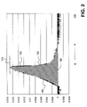
- the algorithms may be formulated with relatively simple mathematical techniques such as integration and maximum value as illustrated in FIG. 2 .
- FIG. 2 is a graph 150 of a waveform 152 (e.g., profile of weld characteristic captured by one of the detectors) illustrating different attributes (or parameters) that may be measured and/or used in an exemplary embodiment according to the present invention.
- a waveform 152 e.g., profile of weld characteristic captured by one of the detectors
- FIG. 2 is a graph 150 of a waveform 152 (e.g., profile of weld characteristic captured by one of the detectors) illustrating different attributes (or parameters) that may be measured and/or used in an exemplary embodiment according to the present invention.
- algorithms including simple mathematical, algebraic and/or calculus operations such as maximum, minimum, slopes, integration, etc. may be used to obtain single value outputs for attributes (parameters or properties) that may be useful for distinguishing good welds from bad welds.
- the algorithms may be normalized to facilitate comparison.
- the waveform 152 has properties of a maximum 154 , a falling slope 156 , a rising slope 158 , and an integral 160 of the area under the waveform.
- the algorithms may be implemented using Microsoft® Excel formulas and/or Visual Basic® programming.
- Microsoft® and Visual Basic® are registered trademarks of Microsoft Corporation, a Delaware corporation, Redmond, Wash.
- the decision making process is improved by algorithm results having single values for the attributes.
- Using single values for decision making is typically easier to implement than pattern matching and/or applying advanced mathematical techniques to the acquired waveform.
- single data values for the attributes may be used as a quantitative measure of the weld performance. The quantitative result can easily be compared against a predetermined value for a “good” or “bad” judgment.
- joint quality measurements themselves single values, may be correlated with algorithm results to provide a measure of joint quality.
- FIG. 3A illustrates a process of setting up (i.e., process development) for and performing weld monitoring (i.e., process control) in an exemplary embodiment according to the present invention.
- Steps 200 – 208 are process development steps used to initially set up the weld monitor, and are typically run at the beginning of a weld process.
- steps 210 and 212 are process control steps that may be run repeatedly to provide process control to an on-going weld process.
- welds e.g., test welds
- weld characteristics are captured (i.e., profiles of the weld characteristics (e.g., reflection, IR and/or acoustic signal) are taken over time for different laser energy levels, etc.).
- single data values are determined for one or more attributes (or parameters) for each weld characteristic by running algorithm(s) selected from a library of algorithms associated with the attributes. For example, for each of the weld characteristics (reflection, acoustic, IR, etc.), the single values for the attributes are determined through mathematical algorithms (maximum, minimum, slopes, integration, other algebraic/calculus functions, etc.) and the single values are plotted.
- the attributes may also be defined for a time period, for example, starting at the beginning of the laser pulse. All attributes may be represented on the same graph for comparison purposes. For example, FIG. 8 shows a graph of various different attributes with respect to a focus position. It can be seen from FIG. 8 that the values for the attributes change as the focus position varies from in focus to out of focus.
- a weld quality is determined for each of the welds. Some welds may be determined to be “good” while others may be determined to be “bad.” The weld quality may be assessed through physical testing and/or visual inspection. The physical testing may include testing for weld strength, weld interface area, weld cross-section, etc., and may be ascertained through destructive testing. For example in an exemplary embodiment, the weld quality may be determined for five groups of welds, from a) best-> b) good-> c) fair-> d) poor-> to e) poorest in weld quality. The groups may be defined through different laser settings (e.g., energy level), and each group may contain a number of welds (e.g., 5).
- the single value outputs of the algorithm(s) are correlated with the weld qualities (e.g., from step 204 ) to select an attribute indicative of weld quality.
- the behavior of the selected attribute should be consistent (e.g., increasing or decreasing function with respect to the optimum case) in order to rely on it for distinguishing good welds from bad welds.
- a number of attributes such as, for example, temperature (IR) rising slope, acoustic integral, acoustic rising slope, etc., demonstrate high sensitivity as the focus point moves away the focus parameter value of 0.000 cm (exactly in focus).
- good and bad welds are defined with respect to the single value output of the algorithm associated with the selected attribute for quality control purposes.
- any weld with the weld interface area of 0.085 mm 2 or more may be deemed to be good, while the weld interface area of less than 0.085 mm 2 may be deemed to be bad.
- the weld interface area of 0.085 mm 2 corresponds roughly with the area under the temperature (IR) curve of approximately 0.007.
- step 210 a weld is performed, and the algorithm associated with the selected attribute is run to obtain a corresponding single value output. Then the weld categorized in step 212 as either good or bad weld based on the single value output of the algorithm. For example, for the weld in step 210 , any weld with the temperature (IR) curve of approximately 0.007 (corresponding to the weld interface area of 0.085 mm 2 ) or higher, may be deemed a good weld.
- IR temperature
- FIG. 3B is a flow diagram illustrating a process of adjusting a focus height of a pulsed laser in an exemplary embodiment according to the present invention.
- step 214 a number of welds (testing welds) are performed, and at least a temperature characteristic is captured for each weld. These welds are performed at a different focus height about a predetermined initial focus height.
- the initial focus height may be selected by the system developer or by a user, and should roughly be the focus height at which the laser is in-focus.
- the test weld may be performed first at an approximated in-focus focus height, and the focus height may be adjusted up and down about that initial approximated in-focus focus height, while capturing the temperature characteristic at each focus height.
- a focus height that results in a maximum rising slope (i.e., single value output of the maximum rising slope algorithm or the highest rate of change of temperature) of temperature characteristic is determined as a correct (i.e., in-focus) focus height.
- a correct focus height i.e., in-focus
- the desired attribute e.g., maximum rising slope of the temperature characteristic
- the attribute indicative of the in-focus focus height may also be selected through running one or more algorithms on the welds, determining weld quality for each weld, and then correlating the single value outputs of the algorithms with the weld qualities.
- FIG. 4 illustrates oscilloscope outputs 220 that represents different profiles based on the focus positions, namely, for focus positions of +0.254 cm, +0.127 cm, 0.000 cm, ⁇ 0.127 cm and ⁇ 0.254 cm.
- the profiles 222 illustrate reflection, IR and acoustic profiles for the above focus distance of +0.254 cm.
- the profiles 224 illustrate reflection, IR and acoustics profiles for the above focus distance of +0.127 cm.
- the profiles 226 illustrate reflection, IR and acoustics profiles for at focus case (i.e., distance of 0.000 cm).
- the profiles 228 and 230 illustrate profiles for the below focus distance of ⁇ 0.127 cm and ⁇ 0.254 cm, respectively.
- the working distance may be varied during focal position variation welds and the algorithm results may display strong sensitivity to the variation.
- Spot welds may be performed in a bead-on-plate configuration.
- a LW50A (a Unitek-Miyachi laser welder) pulsed Nd:YAG laser capable of 5 kW peak power may be used to take the profiles.
- any other power-feedback laser may be used to take the profiles.
- the laser pulses may produce weld nuggets measuring 0.610 mm in diameter and 0.305 mm in depth while in focus.
- a z-axis stepper motor may be used for increments of 0.127 cm to change the focus height in an exemplary embodiment according to the present invention.
- the trends in the weld profile and raw monitor signals may be seen in FIG. 4 .
- the weld profile walls may be steep at focus but may gradually become shallow (conduction weld type) as the focus height moves away from the focal position (above and below focus).
- all of the monitor signals may change shape when moving from in focus to out of focus.
- the temperature (IR) signal may have the largest area under the curve due to a strong up-slope (rising slope) at focus.
- the temperature (IR) up-slope may decrease and create a triangle shape as the working distance moves out of focus (above and below).
- the acoustic signal shape may have maximum values in the beginning and the largest negative dip after the pulse. The positive values and negative dip may become less pronounced away from focus (above and below).
- FIGS. 5A–5C , 6 A– 6 C and 7 A– 7 D illustrate processes (mathematical algorithms) for deriving single value outputs for attributes (or parameters) for defining weld quality based on different weld characteristics as the focus point is varied in an exemplary embodiment according to the present invention.
- FIGS. 5A–5C illustrate processes (mathematical algorithms) for deriving single value outputs for attributes for defining weld quality based on reflection profiles in an exemplary embodiment according to the present invention.
- step 250 of FIG. 5A the maximum value of the reflection signal is determined for each profile, and the profile with the largest maximum value is selected in step 252 as the profile for the at-focus (or in-focus) weld.
- step 260 of FIG. 5B the reflection profiles are integrated from 0.4 ms to 5 ms, and the maximum value is determined for each profile in step 262 .
- step 264 the profile with the smallest maximum value is determined as the profile for the at-focus weld.
- step 270 of FIG. 5C the reflection profiles are integrated from 0 ms to 5 ms, and the maximum value is determined for each profile in step 272 .
- step 274 the profile with the smallest maximum value is determined as the profile for the at-focus weld.
- FIGS. 6A–6C illustrate processes (mathematical algorithms) for deriving single value outputs for attributes for defining weld quality based on IR profiles in an exemplary embodiment according to the present invention.
- step 300 of FIG. 6A the maximum value of the reflection signal is determined for each profile, and the profile with the largest maximum value is selected in step 302 as the profile for the at-focus (or in-focus) weld.
- step 310 of FIG. 6B a slope is taken from 0.0 ms to 0.5 ms, and the maximum value is determined for each profile in step 312 .
- step 314 the profile with the largest maximum value is determined as the profile for the at-focus weld.
- step 320 of FIG. 6C the IR profiles are integrated from 0 ms to 5 ms, and the maximum value is determined for each profile in step 322 .
- step 324 the profile with the largest maximum value is determined as the profile for the at-focus weld.
- FIGS. 7A–7D illustrate processes (mathematical algorithms) for deriving single value outputs for attributes for defining weld quality based on acoustic profiles in an exemplary embodiment according to the present invention.
- step 350 of FIG. 7A the minimum value of the acoustic signal is determined for each profile, and the profile with the smallest minimum value is selected in step 352 as the profile for the at-focus (or in-focus) weld.
- step 360 of FIG. 7B the profiles are integrated from 0.0 ms to 0.5 ms, and the maximum value is determined for each profile in step 362 .
- step 364 the profile with the largest maximum value is determined as the profile for the at-focus weld.
- step 370 of FIG. 7C the acoustic profiles are integrated from 5 ms to 11.5 ms, and the maximum value is determined for each profile in step 372 .
- the profile with the smallest minimum value is determined as the profile for the at-focus weld.
- step 380 of FIG. 7D the slope is taken from 0.25 ms to 0.4 ms, and the maximum value is determined for each profile in step 382 .
- step 384 the profile with the largest maximum value is determined as the profile for the at-focus weld.
- algorithm results exhibit strong sensitivity to the focal position.
- the algorithm trends may be categorized as low, average and high sensitivities.
- High sensitivity algorithms for example, may have a (normalized) value of 1 at the focal position and low values ( ⁇ 0.3) at the out-of-focus extremes.
- Lower sensitivity algorithms e.g., with the maximum of ⁇ 0.8
- IR and acoustic algorithms may be most sensitive to the focal (or focus) position.
- FIG. 9A illustrates a lap joint weld 420 , where base materials 424 and 426 are joined together by a weld 422 in an exemplary embodiment according to the present invention.
- the base material 424 may be a 0.102 mm thick stainless steel (e.g., Type 304 ) and the base material 426 may be a 0.635 mm thick stainless steel (e.g., Type 304 ).
- the laser may be a LW50A laser, and the 400SI optical fiber maybe used to carry laser signal for welding.
- the laser signal may be focused by 100/00 FX Focus Head (a Unitek-Miyachi FX series focus head) or any other suitable focus head.
- the welding for example, may be performed at 4 degree tilt, and approximately 0.480 mm welds may be realized.
- the penetration depth may be varied for a lap joint weld.
- the laser weld monitor results may correlate with the penetration depth variation.
- the laser pulse energy may be increased by increasing the pulse width at a fixed peak power of 1.4 kW.
- FIG. 9B illustrates performing a tensile pull test 430 to measure the strength of the weld.
- the tensile pull test is a destructive test where the welded base materials 424 and 426 are pulled apart to measure how much force that they can withstand without breaking apart.
- FIG. 9C shows different pulse energy applied to effect the welds, and the duration of the pulse, which may vary with the energy levels.
- FIG. 9D illustrates a top view 434 of a weld interface area 436 on the surface of the bottom base material 426 .
- FIG. 10 illustrates graphs 440 of single value outputs for attributes generated from different algorithms applied to weld characteristics for different weld penetration depths in an exemplary embodiment according to the present invention. It can be seen that some trends are unexpected, some are expected but have low sensitivity, while some are expected and have good sensitivity.
- the expected trends having good sensitivity for example, are temperature (IR) integral, acoustic minimum negative, acoustic integral and acoustic upslope, as can be seen on FIG. 10 .
- FIGS. 11–14 illustrate the results of the correlation between weld strength and monitor signals in an exemplary embodiment according to the present invention.
- the linear fit between the acoustic integral and quality outputs may maintain an R 2 value greater than 0.95 and the temperature (IR) integral fit may reach similar R 2 values.
- Multiple welds may be performed for repeatability measurement purposes.
- the scatter of data points may be indicative of both the monitor and joint quality measurement variation.
- the strong correlation may be maintained over multiple welds, and would indicate the potential of the exemplary embodiment or use in industrial applications.
- FIG. 11 illustrates a graph 450 of a correlation between weld interface area and temperature (IR) integral.
- FIG. 15 is a block diagram of a weld monitoring system 500 for capturing (or measuring) and analyzing laser weld characteristics in another exemplary embodiment according to the present invention.
- reflected laser radiation i.e., reflection signal
- infrared radiation i.e., IR signal
- a closed circuit television (CCTV) camera 502 is used to capture images of welding parts prior to and/or after welding.
- CCTV closed circuit television
- Many of the components in the system 500 of FIG. 15 may be similar or identical to the components in the system 100 of FIG. 1 .
- the output of the photodiodes and/or the CCTV camera may be provided for processing and analysis to a digitizer and/or a data acquisition and processing equipment similar to the one used in the system 100 .
- the photodiode 526 is used to measure the reflection signal (e.g., 1064 nm) from the weld surface.
- the photodiode 526 may be a Si (silicon) photodiode with a peak response at 800 nm.
- the photodiode 524 is used to measure the IR signal.
- the photodiode 524 may be an InGaAs (indium gallium arsenide) photodiode with a peak response at 1550 nm.
- other sensors or detectors e.g., monitor sensor, machine vision sensor, etc.
- instead of or in addition to the photodiodes 524 and/or 526 may be used to measure laser weld characteristics.
- a laser signal may be provided via a fiber optic cable 522 , which may be any suitable optical fiber.
- the laser signal may be provided by a pulsed 1064 nm Nd:YAG laser.
- the laser signal passes through a collimator 518 , which may be any suitable collimator.
- the laser signal then may be applied to a dichroic mirror 510 , which for example, may reflect 99.5% at 1064 nm and 10% at 633 nm.
- the reflected laser signal is focused by a suitable focus lens 512 onto a weld surface.
- the reflected signal passes back through the focus lens 512 and the dichroic mirror 510 , reflects off the dichroic mirror 508 (e.g., 100% at 1064 nm and 10% at 663 nm), gets filtered at 1064 nm with an interference filter 516 (e.g., 1064+/ ⁇ 10 nm interference filter), and is focused onto the photodiode 526 by a lens 520 , which for example, may be a 75 mm (mili-meter) plano-convex lens.
- a lens 520 which for example, may be a 75 mm (mili-meter) plano-convex lens.
- An IR signal from the weld surface passes through the focus lens 512 and the dichroic mirrors, and is applied to a semiconductor laser mirror 506 , which for example, may reflect 100% at 1400–1700 nm.
- the semiconductor laser mirror 506 may be substituted with a 1200–1300 nm mirror.
- the IR signal is then focused on to the photodiode 524 by a lens 514 , which for example, may be a 25 mm plano-convex lens.
- long pass filters such as the long pass filters 106 of FIG. 1 , may not be needed, because the semiconductor laser mirror 506 reflects radiation between the wavelength of 1400–1700 nm to the photodiode 524 .
- the portion of the optical signal from laser weld not reflected by the dichroic mirrors or the semiconductor laser mirror 506 is provided to the CCTV camera 502 through a video lens 504 .
- the CCTV camera 502 is co-axial with the weld process. In other words, the camera is aligned to the position where the weld will take place.
- the working distance of camera may be increased, and may result in a comparatively reduced field of view and/or magnification.
- FIG. 16A is a block diagram of a weld monitoring system 550 for capturing (or measuring) and analyzing laser weld characteristics in yet another exemplary embodiment according to the present invention.
- reflected laser radiation i.e., reflection signal
- infrared radiation i.e., IR signal
- a two-color detector 552 i.e., a two-color detector 552 .
- a closed circuit television (CCTV) camera 568 is used to capture images of welding parts prior to and/or after welding.
- other sensors or detectors e.g., monitor sensor, machine vision sensor, etc.
- the components in the system 550 of FIG. 16A may be similar or identical to the components in the system 100 of FIG. 1 .
- the output of the photodiodes and/or the CCTV camera may be provided for processing and analysis to a digitizer and/or a data acquisition and processing equipment similar to the one used in the system 100 .
- a laser signal may be provided via a fiber optic cable 570 , which may be any suitable optical fiber.
- the laser signal may be provided by a 1064 nm pulsed Nd:YAG laser.
- the laser signal passes through a collimator 564 , which may be any suitable collimator.
- the laser signal then may be applied to a dichroic mirror 560 , which for example, may reflect 99.5% at 1064 nm and 10% at 633 nm.
- the reflected laser signal is focused by a suitable focus lens 562 onto a weld surface.
- the optical signal from the weld process includes the reflection signal and the IR signal as well as other optical signals.
- the optical signal passes through the focus lens 562 and the dichroic mirror 560 , and applied to a cold mirror 558 .
- the cold mirror 558 may reflect 90% at 450–750 nm and may reflect only 10% in IR (infrared).
- the portion of the optical signal reflected by the cold mirror 558 is provided to the CCTV camera 568 through a video lens 566 .
- the portion of the optical signal that passes through the cold mirror 558 is applied to the two-color detector 552 through a lens 554 , which for example, may be a 25 mm plano convex lens.
- the optical signal portion may also be passed through a 1.2–1.31 ⁇ m semiconductor mirror or a longpass filter (>1 ⁇ m), either of which is optional.
- FIG. 16B is a cross-sectional diagram of a two-color detector 580 , which may be applied as the two-color detector 552 of FIG. 16A .
- the two-color detector 580 includes a top detector 582 and a bottom detector 584 .
- the top detector 582 has an active area greater than equal to that of the bottom detector 584 .
- the top detector for example, may be a silicon detector for detecting the reflection signal at 1064 nm.
- the bottom detector for example, may be an InGaAs detector for detecting the IR signal at 1200–1700 nm.
- FIG. 16C illustrates detector responses 592 and 594 for the detectors that make up the two-color detector of FIG. 16B .
- the detector response 592 for example, is for the top detector (e.g., silicon detector) with the peak around 1000 nm
- the detector response 594 for example, is for the bottom detector (e.g., InGaAs detector) with the peak around 1500 nm.
- the system 550 is more compact in size, and includes fewer components. Further, working or image distance of the CCTV camera 568 is not lengthened appreciably. However, when a two-color detector is used, IR radiation may be reduced by 30% as it passes through the top detector (i.e., Si detector). Further, the top detector may not absorb all of the 1064 nm signal, and may contaminate the signal applied at the InGaAs detector.
- the top detector i.e., Si detector
- FIG. 17 is a block diagram of a weld monitoring system 600 for capturing (or measuring) and analyzing laser weld characteristics in still another exemplary embodiment according to the present invention.
- reflected laser radiation and infrared radiation are captured by photodiodes 602 and 628 , respectively.
- a closed circuit television (CCTV) camera 608 is used to capture images of welding parts prior to and/or after welding.
- CCTV closed circuit television
- Many of the components in the system 600 of FIG. 17 may be similar or identical to the components in the system 100 of FIG. 1 .
- the output of the photodiodes and/or the CCTV camera may be provided for processing and analysis to a digitizer and/or a data acquisition and processing equipment similar to the one used in the system 100 .
- the photodiode 628 is used to the reflection signal (e.g., 1064 nm) from the weld surface.
- the photodiode 628 may be a Si (silicon) photodiode with a peak response at 800 nm.
- the photodiode 602 is used to measure the IR signal.
- the photodiode 602 may be an InGaAs photodiode with a peak response at 1550 nm.
- other sensors or detectors e.g., monitor sensor, machine vision sensor, etc.
- instead of or in addition to the photodiodes 602 and/or 628 may be used to measure laser weld characteristics.
- a laser signal may be provided via a fiber optic cable 626 , which may be any suitable optical fiber.
- the laser signal may be provided by a pulsed 1064 nm Nd:YAG laser.
- the laser signal passes through a collimator 622 , which may be any suitable collimator.
- the laser signal then may be applied to a dichroic mirror 620 , which for example, may reflect 99.5% at 1064 nm and 10% at 633 nm.
- the reflected laser signal then passes through a cold mirror 624 and is focused by a suitable focus lens 612 onto a weld surface.
- the cold mirror 624 for example, may reflect 90% at 450–750 mm and 10% at IR.
- An optical signal from the weld surface is applied first at the cold mirror 624 through the focus lens 612 .
- the 450–750 nm component of the optical signal is mostly reflected by the cold mirror 624 for detection by the CCTV camera 608 through a video lens 610 .
- the CCTV camera 608 is coaxial with the weld process, and working or image distance of the camera is shortened.
- the cold mirror 612 may reflect and absorb some of the IR radiation.
- the reflection signal passes back through the dichroic mirror 620 , reflects off the dichroic mirror 618 (e.g., 100% at 1064 nm and 10% at 663 nm), gets filtered at 1064 nm with an interference filter 614 (e.g., 1064+/ ⁇ 10 nm interference filter), and is focused onto the photodiode 628 by a lens 616 , which for example, may be a 75 mm (mili-meter) plano-convex lens.
- a lens 616 which for example, may be a 75 mm (mili-meter) plano-convex lens.
- the IR signal from the weld surface passes through the focus lens 612 , the cold mirror 624 and the dichroic mirrors, and gets filtered by three long pass filters 106 (e.g., at >1400 nm), and is focused on to the photodiode 602 by a lens 604 , which for example, may be a 25 mm plano-convex lens.
- a sensor 668 (e.g., weld monitor sensor) is internal to the laser as illustrated in a laser system 650 of FIG. 18 .
- the laser system includes a laser cavity 652 , which provides a laser output.
- the laser output is reflected by mirrors 654 and 656 , and then coupled to a multi-mode optical fiber 660 via a fiber input coupler 658 .
- the laser output is applied at the end of the multi-mode optical fiber 660 to an end effector 662 , and then to a weld surface 664 .
- a reflected laser signal is provided back to the laser, and is detected by the sensor 668 .
- Using an internal sensor, such as the sensor 668 may result in an improved space allotment near the weld.
- different welds may be performed to assess weld characteristics, and generate profiles therefrom.
- interface gap variations, butt weld joint variations and/or fillet joint weld variations may be performed to obtain weld characteristics and develop algorithms for weld quality control.
Abstract
Description
Claims (22)
Priority Applications (1)
| Application Number | Priority Date | Filing Date | Title |
|---|---|---|---|
| US10/673,828 US7129438B2 (en) | 2002-07-31 | 2003-09-29 | Laser weld monitor |
Applications Claiming Priority (2)
| Application Number | Priority Date | Filing Date | Title |
|---|---|---|---|
| US10/210,009 US6670574B1 (en) | 2002-07-31 | 2002-07-31 | Laser weld monitor |
| US10/673,828 US7129438B2 (en) | 2002-07-31 | 2003-09-29 | Laser weld monitor |
Related Parent Applications (1)
| Application Number | Title | Priority Date | Filing Date |
|---|---|---|---|
| US10/210,009 Continuation US6670574B1 (en) | 2002-07-31 | 2002-07-31 | Laser weld monitor |
Publications (2)
| Publication Number | Publication Date |
|---|---|
| US20040069754A1 US20040069754A1 (en) | 2004-04-15 |
| US7129438B2 true US7129438B2 (en) | 2006-10-31 |
Family
ID=29735431
Family Applications (2)
| Application Number | Title | Priority Date | Filing Date |
|---|---|---|---|
| US10/210,009 Expired - Lifetime US6670574B1 (en) | 2002-07-31 | 2002-07-31 | Laser weld monitor |
| US10/673,828 Expired - Lifetime US7129438B2 (en) | 2002-07-31 | 2003-09-29 | Laser weld monitor |
Family Applications Before (1)
| Application Number | Title | Priority Date | Filing Date |
|---|---|---|---|
| US10/210,009 Expired - Lifetime US6670574B1 (en) | 2002-07-31 | 2002-07-31 | Laser weld monitor |
Country Status (6)
| Country | Link |
|---|---|
| US (2) | US6670574B1 (en) |
| EP (1) | EP1415755B1 (en) |
| JP (2) | JP2004066340A (en) |
| KR (1) | KR101007724B1 (en) |
| CN (1) | CN1310734C (en) |
| DE (1) | DE60323315D1 (en) |
Cited By (12)
| Publication number | Priority date | Publication date | Assignee | Title |
|---|---|---|---|---|
| US20090279096A1 (en) * | 2005-12-23 | 2009-11-12 | Posco | Apparatus and method for on-line detecting welding part of strip |
| DE102008058422A1 (en) * | 2008-11-21 | 2010-05-27 | Precitec Itm Gmbh | Monitoring laser machining process to be carried out on workpiece, comprises detecting actual measuring values by sensor, which monitors the laser machining process, and determining actual characteristic values from actual measuring values |
| WO2011120672A2 (en) | 2010-04-01 | 2011-10-06 | Baden-Württemberg Stiftung Ggmbh | Method for operating a device for processing material, and device |
| US20120012644A1 (en) * | 2010-02-18 | 2012-01-19 | Rolls-Royce Plc | Apparatus and a method of determining the quality of a friction weld |
| ITRM20100461A1 (en) * | 2010-08-31 | 2012-03-01 | Consiglio Nazionale Ricerche | METHOD OF IDENTIFICATION OF DEFECTIVENESS IN THE LASER WELDING PROCESS CONTINUES OF METAL PARTS |
| US20120055909A1 (en) * | 2009-05-15 | 2012-03-08 | Hideaki Miyake | Method of laser-welding and method of manufacturing battery including the same |
| WO2015007322A1 (en) | 2013-07-18 | 2015-01-22 | Toyota Motor Europe Nv/Sa | Systems and methods for assuring and improving process quality |
| US9056368B2 (en) | 2008-11-21 | 2015-06-16 | Precitec Kg | Method and device for monitoring a laser processing operation to be performed on a workpiece and laser processing head having such a device |
| US20180147665A1 (en) * | 2016-11-29 | 2018-05-31 | Fanuc Corporation | Machine learning device and robot system to learn processing order of laser processing robot and machine learning method thereof |
| US10101201B2 (en) | 2013-11-13 | 2018-10-16 | Medtronic, Inc. | System for continuous laser beam monitoring and analysis |
| US10239090B2 (en) | 2014-04-22 | 2019-03-26 | Photofusion Technologies Limited | Method and apparatus for coating a substrate utilizing multiple lasers while increasing quantum yield |
| US11815877B2 (en) | 2018-05-07 | 2023-11-14 | Fronius International Gmbh | Method for automatically determining optimum welding parameters for carrying out a weld on a workpiece |
Families Citing this family (123)
| Publication number | Priority date | Publication date | Assignee | Title |
|---|---|---|---|---|
| SE521787C2 (en) * | 2002-04-05 | 2003-12-09 | Volvo Aero Corp | Device and method for controlling a welding area, arrangement and method for controlling a welding operation, computer program and computer program product |
| DE10234242B4 (en) * | 2002-07-09 | 2005-10-27 | Airbus Deutschland Gmbh | Arrangement and method for controlling the seam position of a laser-beam-applied profile |
| KR20050084436A (en) * | 2002-12-20 | 2005-08-26 | 코닌클리케 필립스 일렉트로닉스 엔.브이. | A method and a device for laser spot welding |
| DE102004001166B4 (en) * | 2003-02-28 | 2007-03-15 | Daimlerchrysler Ag | Method for laser welding with preheating and / or reheating in the region of the weld |
| US8921733B2 (en) * | 2003-08-11 | 2014-12-30 | Raydiance, Inc. | Methods and systems for trimming circuits |
| JP2005118808A (en) * | 2003-10-15 | 2005-05-12 | Disco Abrasive Syst Ltd | Laser beam machining device |
| US7344671B2 (en) * | 2003-11-26 | 2008-03-18 | Glopak Inc. | Optical sealing clamp and a method for sealing and cutting polymeric sheets with a laser |
| KR100588042B1 (en) * | 2004-01-14 | 2006-06-09 | 한국과학기술연구원 | Interactive presentation system |
| KR101102148B1 (en) * | 2004-03-18 | 2012-01-02 | 부광석 | A welding seam tracking system using one dimensional CCD |
| CA2463409A1 (en) * | 2004-04-02 | 2005-10-02 | Servo-Robot Inc. | Intelligent laser joining head |
| JP2005347415A (en) * | 2004-06-01 | 2005-12-15 | Miyachi Technos Corp | Electric part mounting method |
| US20060000810A1 (en) * | 2004-06-30 | 2006-01-05 | Kerr James A | Method of and system for dynamic laser welding |
| DE502004001425D1 (en) * | 2004-07-08 | 2006-10-19 | Trumpf Laser Gmbh & Co Kg | Laser welding method and apparatus |
| JP2006247681A (en) * | 2005-03-09 | 2006-09-21 | Miyachi Technos Corp | Monitoring device for laser beam machining |
| JP4822737B2 (en) * | 2005-04-22 | 2011-11-24 | ミヤチテクノス株式会社 | Laser welding method and laser welding apparatus |
| DE102005024085A1 (en) * | 2005-05-25 | 2006-11-30 | Precitec Kg | Laser processing step e.g. laser welding/cutting process, monitoring device for workpiece, has radiation-sensitive receiver e.g. photodiode, and camera e.g. CCD image sensor, that simultaneously supply output signals to evaluation circuit |
| JP2007054881A (en) * | 2005-08-26 | 2007-03-08 | Miyachi Technos Corp | Laser machining monitoring device |
| ES2302169T3 (en) | 2005-09-22 | 2008-07-01 | C.R.F. SOCIETÀ CONSORTILE PER AZIONI | PROCEDURE FOR CONTROLLING THE QUALITY OF LASER WELDING PROCESSES, CONTROL SYSTEM AND PROGRAM PRODUCT OF THE SAME. |
| JP2007229786A (en) * | 2006-03-02 | 2007-09-13 | Sumitomo Heavy Ind Ltd | Laser machining system and focussing control method |
| EP2032345B1 (en) * | 2006-06-20 | 2010-05-05 | Katholieke Universiteit Leuven | Procedure and apparatus for in-situ monitoring and feedback control of selective laser powder processing |
| WO2008001808A1 (en) * | 2006-06-30 | 2008-01-03 | O.M.C Co., Ltd. | Laser machining apparatus |
| DE602006007580D1 (en) * | 2006-08-07 | 2009-08-13 | Lvd Co | Arrangement and method for on-line monitoring of the laser process of a workpiece using a heat chamber detector and a tilted mirror |
| DE102007035715A1 (en) * | 2006-12-27 | 2008-07-03 | Robert Bosch Gmbh | Laser beam processing device for hardening of workpieces, includes device for imaging reflected laser radiation from workpiece onto sensor |
| DE102007024789B3 (en) | 2007-05-26 | 2008-10-23 | Trumpf Werkzeugmaschinen Gmbh + Co. Kg | Method for detecting defects in a weld during a laser welding process |
| JP5027606B2 (en) * | 2007-09-26 | 2012-09-19 | 株式会社キーエンス | Laser machining apparatus, machining data generation method, and computer program |
| JP5205926B2 (en) * | 2007-11-09 | 2013-06-05 | トヨタ自動車株式会社 | Welding quality inspection device and welding quality inspection method |
| US20090139969A1 (en) * | 2007-11-29 | 2009-06-04 | Global Nuclear Fuel - Americas Llc | Laser welding of castings to minimize distortion |
| GB2458304A (en) * | 2008-03-13 | 2009-09-16 | Gsi Group Ltd | Process Monitoring |
| US9352411B2 (en) | 2008-05-28 | 2016-05-31 | Illinois Tool Works Inc. | Welding training system |
| US20100140236A1 (en) * | 2008-12-04 | 2010-06-10 | General Electric Company | Laser machining system and method |
| JP5044806B2 (en) * | 2009-03-13 | 2012-10-10 | 国立大学法人大阪大学 | Real-time welding quality judgment device and judgment method |
| WO2010135006A2 (en) * | 2009-05-22 | 2010-11-25 | The State Of Oregon Acting By And Through The State Board Of Higher Education On Behalf Of The Portland State University | Sensitive gas-phase fluorimeter at ambient pressure for nitrogen dioxide |
| WO2011026638A1 (en) * | 2009-09-04 | 2011-03-10 | Precitec Kg | Method for classifying a laser process and a laser material processing head using the same |
| IT1397985B1 (en) * | 2010-02-08 | 2013-02-04 | Prima Ind Spa | MONITORING PROCEDURE FOR THE QUALITY OF LASER PROCESSING PROCESSES AND ITS SYSTEM |
| EP2409808A1 (en) * | 2010-07-22 | 2012-01-25 | Bystronic Laser AG | Laser processing machine |
| JP5671873B2 (en) * | 2010-08-09 | 2015-02-18 | 日産自動車株式会社 | Laser welding monitoring device |
| WO2012037465A1 (en) | 2010-09-16 | 2012-03-22 | Raydiance, Inc. | Laser based processing of layered materials |
| US8669507B2 (en) * | 2010-10-22 | 2014-03-11 | Industrial Technology Research Institute | Laser scanning device |
| US20120097833A1 (en) * | 2010-10-22 | 2012-04-26 | Industrial Technology Research Institute | Laser scanning device |
| US8661905B2 (en) * | 2010-11-09 | 2014-03-04 | Georgia Tech Research Corporation | Non-contact microelectronic device inspection systems and methods |
| US9289852B2 (en) | 2011-01-27 | 2016-03-22 | Bystronic Laser Ag | Laser processing machine, laser cutting machine, and method for adjusting a focused laser beam |
| EP2667998B1 (en) | 2011-01-27 | 2020-11-18 | Bystronic Laser AG | Laser processing machine and method for centering a focused laser beam |
| DE102011005004A1 (en) * | 2011-03-03 | 2012-09-06 | Brose Fahrzeugteile Gmbh & Co. Kommanditgesellschaft, Coburg | Method for monitoring a lateral offset of an actual weld seam course with respect to a desired weld seam profile, assembly and motor vehicle seat |
| SE535767C2 (en) | 2011-04-28 | 2012-12-11 | Westinghouse Electric Sweden | Procedure for welding nuclear fuel rod |
| DE102011103246A1 (en) * | 2011-06-03 | 2012-12-06 | Volkswagen Aktiengesellschaft | Method and device for joining components by means of energy-beam welding |
| US9101994B2 (en) | 2011-08-10 | 2015-08-11 | Illinois Tool Works Inc. | System and device for welding training |
| EP2567773B1 (en) | 2011-09-08 | 2017-04-19 | TRUMPF Werkzeugmaschinen GmbH + Co. KG | Method for inspecting seam quality during a laser welding process |
| JP5338890B2 (en) * | 2011-12-15 | 2013-11-13 | Jfeスチール株式会社 | Laser welding welding position detection apparatus and welding position detection method |
| US9573215B2 (en) | 2012-02-10 | 2017-02-21 | Illinois Tool Works Inc. | Sound-based weld travel speed sensing system and method |
| US9368045B2 (en) | 2012-11-09 | 2016-06-14 | Illinois Tool Works Inc. | System and device for welding training |
| US9583014B2 (en) | 2012-11-09 | 2017-02-28 | Illinois Tool Works Inc. | System and device for welding training |
| US9713852B2 (en) | 2013-03-15 | 2017-07-25 | Illinois Tool Works Inc. | Welding training systems and devices |
| US9583023B2 (en) | 2013-03-15 | 2017-02-28 | Illinois Tool Works Inc. | Welding torch for a welding training system |
| US9672757B2 (en) | 2013-03-15 | 2017-06-06 | Illinois Tool Works Inc. | Multi-mode software and method for a welding training system |
| US9666100B2 (en) | 2013-03-15 | 2017-05-30 | Illinois Tool Works Inc. | Calibration devices for a welding training system |
| US9728103B2 (en) | 2013-03-15 | 2017-08-08 | Illinois Tool Works Inc. | Data storage and analysis for a welding training system |
| KR101439758B1 (en) * | 2013-03-26 | 2014-09-16 | 주식회사 포스코 | Apparatus and method of inspecting defect of laser welding |
| CN103252582B (en) * | 2013-04-12 | 2015-05-20 | 浙江大学宁波理工学院 | Laser wire-filling local bionic-texture manufacturing method and equipment for metal functional surfaces |
| US11090753B2 (en) | 2013-06-21 | 2021-08-17 | Illinois Tool Works Inc. | System and method for determining weld travel speed |
| TWI558489B (en) | 2013-11-27 | 2016-11-21 | 財團法人工業技術研究院 | Laser working system utilizing heat radiation image and method thereof |
| US10056010B2 (en) | 2013-12-03 | 2018-08-21 | Illinois Tool Works Inc. | Systems and methods for a weld training system |
| EP2883647B1 (en) | 2013-12-12 | 2019-05-29 | Bystronic Laser AG | Method for configuring a laser machining device |
| US9751149B2 (en) | 2014-01-07 | 2017-09-05 | Illinois Tool Works Inc. | Welding stand for a welding system |
| US10170019B2 (en) | 2014-01-07 | 2019-01-01 | Illinois Tool Works Inc. | Feedback from a welding torch of a welding system |
| US9724788B2 (en) | 2014-01-07 | 2017-08-08 | Illinois Tool Works Inc. | Electrical assemblies for a welding system |
| US10105782B2 (en) | 2014-01-07 | 2018-10-23 | Illinois Tool Works Inc. | Feedback from a welding torch of a welding system |
| US9589481B2 (en) * | 2014-01-07 | 2017-03-07 | Illinois Tool Works Inc. | Welding software for detection and control of devices and for analysis of data |
| US9757819B2 (en) | 2014-01-07 | 2017-09-12 | Illinois Tool Works Inc. | Calibration tool and method for a welding system |
| DE102014202636B4 (en) * | 2014-02-13 | 2016-10-20 | Bayerische Motoren Werke Aktiengesellschaft | Method for producing a weld and component connection |
| JP6180620B2 (en) * | 2014-03-12 | 2017-08-16 | 三菱電機株式会社 | Laser processing head device with camera monitor |
| JP6354350B2 (en) * | 2014-06-05 | 2018-07-11 | 株式会社ジェイテクト | Optical nondestructive inspection method and optical nondestructive inspection apparatus |
| US10307853B2 (en) | 2014-06-27 | 2019-06-04 | Illinois Tool Works Inc. | System and method for managing welding data |
| US10665128B2 (en) | 2014-06-27 | 2020-05-26 | Illinois Tool Works Inc. | System and method of monitoring welding information |
| US9862049B2 (en) | 2014-06-27 | 2018-01-09 | Illinois Tool Works Inc. | System and method of welding system operator identification |
| US9937578B2 (en) | 2014-06-27 | 2018-04-10 | Illinois Tool Works Inc. | System and method for remote welding training |
| US9724787B2 (en) | 2014-08-07 | 2017-08-08 | Illinois Tool Works Inc. | System and method of monitoring a welding environment |
| US11014183B2 (en) | 2014-08-07 | 2021-05-25 | Illinois Tool Works Inc. | System and method of marking a welding workpiece |
| US9875665B2 (en) | 2014-08-18 | 2018-01-23 | Illinois Tool Works Inc. | Weld training system and method |
| JP6079739B2 (en) * | 2014-09-25 | 2017-02-15 | トヨタ自動車株式会社 | Measuring method of laser scanning speed |
| DE112015004532B4 (en) * | 2014-10-02 | 2024-02-01 | Ngk Spark Plug Co., Ltd. | Evaluation method, laser device and method for producing a sensor |
| US11247289B2 (en) | 2014-10-16 | 2022-02-15 | Illinois Tool Works Inc. | Remote power supply parameter adjustment |
| US10239147B2 (en) | 2014-10-16 | 2019-03-26 | Illinois Tool Works Inc. | Sensor-based power controls for a welding system |
| JP6462140B2 (en) * | 2014-10-20 | 2019-01-30 | プレシテック ゲーエムベーハー ウント ツェーオー カーゲー | Equipment for measuring weld seam depth in real time |
| US10112262B2 (en) | 2014-10-28 | 2018-10-30 | General Electric Company | System and methods for real-time enhancement of build parameters of a component |
| US10210773B2 (en) | 2014-11-05 | 2019-02-19 | Illinois Tool Works Inc. | System and method for welding torch display |
| US10204406B2 (en) | 2014-11-05 | 2019-02-12 | Illinois Tool Works Inc. | System and method of controlling welding system camera exposure and marker illumination |
| US10402959B2 (en) | 2014-11-05 | 2019-09-03 | Illinois Tool Works Inc. | System and method of active torch marker control |
| US10373304B2 (en) | 2014-11-05 | 2019-08-06 | Illinois Tool Works Inc. | System and method of arranging welding device markers |
| US10417934B2 (en) | 2014-11-05 | 2019-09-17 | Illinois Tool Works Inc. | System and method of reviewing weld data |
| US10490098B2 (en) | 2014-11-05 | 2019-11-26 | Illinois Tool Works Inc. | System and method of recording multi-run data |
| RU2599920C2 (en) * | 2014-11-20 | 2016-10-20 | Федеральное государственное бюджетное образовательное учреждение высшего профессионального образования "Владимирский государственный университет имени Александра Григорьевича и Николая Григорьевича Столетовых" | Control device for laser thermal strengthening process |
| KR101643187B1 (en) * | 2015-01-23 | 2016-07-29 | 목포대학교산학협력단 | Monitoring and evaluation apparatus for real-time arc welding |
| CN104677751B (en) * | 2015-02-28 | 2017-04-12 | 重庆理工大学 | Quality detection method for resistance-spot-welding spots on basis of calculation of thermal effect of welding process |
| US10427239B2 (en) | 2015-04-02 | 2019-10-01 | Illinois Tool Works Inc. | Systems and methods for tracking weld training arc parameters |
| US10373517B2 (en) | 2015-08-12 | 2019-08-06 | Illinois Tool Works Inc. | Simulation stick welding electrode holder systems and methods |
| US10593230B2 (en) | 2015-08-12 | 2020-03-17 | Illinois Tool Works Inc. | Stick welding electrode holder systems and methods |
| US10438505B2 (en) | 2015-08-12 | 2019-10-08 | Illinois Tool Works | Welding training system interface |
| US10657839B2 (en) | 2015-08-12 | 2020-05-19 | Illinois Tool Works Inc. | Stick welding electrode holders with real-time feedback features |
| JP6680494B2 (en) * | 2015-09-15 | 2020-04-15 | 浜松ホトニクス株式会社 | Laser processing method and laser processing apparatus |
| GB201604097D0 (en) * | 2016-03-09 | 2016-04-20 | Spi Lasers Uk Ltd | Apparatus and method for controlling laser processing of a material |
| JP6290960B2 (en) | 2016-04-04 | 2018-03-07 | ファナック株式会社 | Laser processing equipment with function to reduce reflected light intensity |
| KR20190012175A (en) * | 2016-04-29 | 2019-02-08 | 누부루 인크. | Method of welding visible laser to semiconductor packaging, automotive electrical equipment, battery and other parts |
| EP3257615A1 (en) * | 2016-06-15 | 2017-12-20 | Eidgenössische Materialprüfungs- und Forschungsanstalt EMPA | Quality control of laser welding process |
| CN108021396B (en) * | 2016-11-04 | 2022-07-15 | 罗伯特·博世有限公司 | Sensor driving method and driving system suitable for Windows operating system |
| CN106338337A (en) * | 2016-11-11 | 2017-01-18 | 盐城工学院 | Apparatus for carrying out on-line monitoring on punching quality during laser punching and monitoring method thereof |
| WO2018150547A1 (en) * | 2017-02-17 | 2018-08-23 | ギガフォトン株式会社 | Laser device |
| JP6851862B2 (en) * | 2017-03-06 | 2021-03-31 | 株式会社フジクラ | Laser processing machine and its control method |
| KR101974722B1 (en) * | 2017-05-26 | 2019-05-02 | 전북대학교산학협력단 | Device for real-time quality monitoring and quality control for three dimensional additive manufacturing process and the method for the same |
| KR102039054B1 (en) * | 2017-11-30 | 2019-10-31 | 한국생산기술연구원 | Apparatus and Method for predicting of welding strength |
| CN108311767B (en) * | 2017-12-18 | 2020-08-14 | 武汉凌云光电科技有限责任公司 | Laser welding safety control method and system based on infrared temperature measurement variable emissivity |
| EP3778101B1 (en) * | 2018-04-13 | 2024-01-17 | Panasonic Intellectual Property Management Co., Ltd. | Laser welding device |
| DE102018217526A1 (en) * | 2018-10-12 | 2020-04-16 | Trumpf Werkzeugmaschinen Gmbh + Co. Kg | Method for determining a parameter of a machining process and machine tool |
| DE102018128377A1 (en) * | 2018-11-13 | 2020-05-14 | Trumpf Laser- Und Systemtechnik Gmbh | Method and device for monitoring a welding process for welding workpieces made of glass |
| CN109352115A (en) * | 2018-12-13 | 2019-02-19 | 武汉雷英激光科技有限公司 | A kind of constant temperature high speed and precision laser Soldering machine and its control method |
| KR102530514B1 (en) * | 2018-12-19 | 2023-05-08 | 아이피지 포토닉스 코포레이션 | Materials processing monitoring using imaging signal density determined from in-line coherent imaging (ICI) |
| US11311958B1 (en) * | 2019-05-13 | 2022-04-26 | Airgas, Inc. | Digital welding and cutting efficiency analysis, process evaluation and response feedback system for process optimization |
| US11776423B2 (en) | 2019-07-22 | 2023-10-03 | Illinois Tool Works Inc. | Connection boxes for gas tungsten arc welding training systems |
| US11288978B2 (en) | 2019-07-22 | 2022-03-29 | Illinois Tool Works Inc. | Gas tungsten arc welding training systems |
| JP2022092729A (en) * | 2020-12-11 | 2022-06-23 | 株式会社東芝 | Method for detecting weld state and welding device |
| EP4074492B1 (en) * | 2021-04-13 | 2023-09-20 | Leister Technologies AG | System for joining workpieces of thermoplastic material by through-transmission laser welding |
| IT202100027494A1 (en) * | 2021-10-27 | 2023-04-27 | Marposs Spa | METHOD AND SYSTEM FOR QUALITY CONTROL OF A WELD |
| GB2616336A (en) * | 2021-12-22 | 2023-09-06 | Cavendish Nuclear Ltd | Improvements in and relating to welding and quality control |
| WO2024029530A1 (en) * | 2022-08-03 | 2024-02-08 | 古河電気工業株式会社 | Coil welding device and welding method |
Citations (36)
| Publication number | Priority date | Publication date | Assignee | Title |
|---|---|---|---|---|
| US4007631A (en) | 1975-08-18 | 1977-02-15 | Western Electric Company, Inc. | Method and apparatus for evaluating welds using stress-wave emission techniques |
| US4419562A (en) | 1982-01-19 | 1983-12-06 | Western Electric Co., Inc. | Nondestructive real-time method for monitoring the quality of a weld |
| US4446354A (en) | 1981-05-29 | 1984-05-01 | The United States Of America As Represented By The Secretary Of The Army | Optoelectronic weld evaluation system |
| US4649256A (en) | 1985-01-10 | 1987-03-10 | Nippon Steel Corporation | High-frequency electric resistance welding method using irradiation with a laser beam |
| US5001324A (en) | 1989-09-14 | 1991-03-19 | General Electric Company | Precision joint tracking laser welding system |
| US5038016A (en) | 1988-11-22 | 1991-08-06 | Fiat Auto S.P.A. | Laser welding monitoring system and method |
| US5045669A (en) | 1990-03-02 | 1991-09-03 | General Electric Company | Method and apparatus for optically/acoustically monitoring laser materials processing |
| DE4106008A1 (en) | 1991-02-26 | 1992-08-27 | Fraunhofer Ges Forschung | Constant monitoring of area around laser beam welding process - to determine degree of weld spitting by monitoring brightness centres |
| US5155329A (en) | 1990-01-08 | 1992-10-13 | Mitsubishi Jukogyo Kabushiki Kaisha | Monitoring method and system for laser beam welding |
| US5247155A (en) | 1990-08-09 | 1993-09-21 | Cmb Foodcan Public Limited Company | Apparatus and method for monitoring laser material processing |
| US5272312A (en) | 1989-03-14 | 1993-12-21 | Jurca Marius Christian | Process for quality control of laser beam welding and cutting |
| JPH05337664A (en) | 1991-10-22 | 1993-12-21 | Mitsubishi Heavy Ind Ltd | Laser beam machining monitor |
| US5283418A (en) | 1992-02-27 | 1994-02-01 | Westinghouse Electric Corp. | Automated rotor welding processes using neural networks |
| US5286947A (en) | 1992-09-08 | 1994-02-15 | General Electric Company | Apparatus and method for monitoring material removal from a workpiece |
| DE4234339A1 (en) | 1992-10-12 | 1994-04-14 | Manfred Prof Dr Ing Geiger | Monitoring the quality of a lap weld - by measuring the temp. at the back of the weld and adjusting the laser beam accordingly |
| US5314248A (en) | 1992-03-24 | 1994-05-24 | Comau S.P.A. | Laser device for simultaneous industrial processing and monitoring of temperature |
| US5360960A (en) | 1992-06-26 | 1994-11-01 | Trw Inc. | Light intensity weld monitor |
| US5506386A (en) | 1993-11-30 | 1996-04-09 | Elpatronic Ag | Simultaneous temperature measurements on laser welded seams with at least two pyrometers in relation to monitoring process parameters and weld quality |
| JPH08164489A (en) | 1994-12-13 | 1996-06-25 | Toshiba Corp | Equipment for judging quality of laser beam welding |
| US5607605A (en) | 1994-07-08 | 1997-03-04 | Ngk Spark Plug Co., Ltd. | Laser welding device, a method of checking welding condition and a method of making a center electrode for a spark plug |
| US5651903A (en) | 1995-10-12 | 1997-07-29 | Trw Inc. | Method and apparatus for evaluating laser welding |
| US5674415A (en) | 1996-01-22 | 1997-10-07 | The University Of Chicago | Method and apparatus for real time weld monitoring |
| US5681490A (en) | 1995-09-18 | 1997-10-28 | Chang; Dale U. | Laser weld quality monitoring system |
| US5728992A (en) | 1996-02-29 | 1998-03-17 | Westinghouse Electric Corporation | Apparatus and method for real time evaluation of laser welds especially in confined spaces such as within heat exchanger tubing |
| JPH1177345A (en) | 1997-09-12 | 1999-03-23 | Tokai Rika Co Ltd | Laser beam welding machine, automatic welding equipment and normal/defective discrimination method for laser beam welding machine |
| US5886319A (en) | 1992-08-05 | 1999-03-23 | Loughborough University Innovations Limited | Automatic operations on materials |
| WO1999014640A2 (en) | 1997-09-12 | 1999-03-25 | Powerlasers Ltd. | Self-adapting neural-fuzzy network for real-time process control |
| US5961859A (en) | 1997-10-23 | 1999-10-05 | Trw Inc. | Method and apparatus for monitoring laser weld quality via plasma size measurements |
| JP2000084683A (en) | 1998-09-08 | 2000-03-28 | Laser Oyo Kogaku Kenkyusho:Kk | Method and device for abnormality monitoring at laser beam welding |
| US6075220A (en) | 1998-02-12 | 2000-06-13 | Sandia Corporation | Optical penetration sensor for pulsed laser welding |
| JP2000271768A (en) | 1999-03-23 | 2000-10-03 | Nissan Motor Co Ltd | Monitoring method of quality for yag laser beam welded part |
| US6188041B1 (en) | 1998-11-13 | 2001-02-13 | Korea Atomic Energy Research Institute | Method and apparatus for real-time weld process monitoring in a pulsed laser welding |
| US6204469B1 (en) | 1999-03-04 | 2001-03-20 | Honda Giken Kogyo Kabushiki Kaisha | Laser welding system |
| DE19957163C1 (en) | 1999-11-27 | 2001-08-09 | Thyssenkrupp Stahl Ag | Method and device for quality control of the seam on sheets or strips butt welded with a laser |
| US6329635B1 (en) | 1998-10-30 | 2001-12-11 | The University Of Chicago | Methods for weld monitoring and laser heat treatment monitoring |
| US6344625B1 (en) | 2000-05-30 | 2002-02-05 | Korea Atomic Energy Research Institute | Method and apparatus for monitoring the size variation and the focus shift of a weld pool in laser welding |
Family Cites Families (18)
| Publication number | Priority date | Publication date | Assignee | Title |
|---|---|---|---|---|
| JPS6016877B2 (en) * | 1978-12-15 | 1985-04-27 | 株式会社東芝 | Laser welding management method |
| JPS59159291A (en) * | 1983-03-03 | 1984-09-08 | Mitsubishi Heavy Ind Ltd | Laser focusing method |
| JPS62114786A (en) * | 1985-11-14 | 1987-05-26 | Fujitsu Ltd | Method for monitoring processing condition |
| CN1027579C (en) * | 1991-11-20 | 1995-02-08 | 华中理工大学 | Real time monitoring method for continuous laser welding |
| JPH0618433A (en) * | 1992-06-30 | 1994-01-25 | Mitsubishi Electric Corp | Bonding unit and method |
| JPH0716779A (en) * | 1993-06-30 | 1995-01-20 | Matsushita Electric Ind Co Ltd | Focusing device for laser beam machine |
| AUPO607397A0 (en) * | 1997-04-08 | 1997-05-01 | University Of Sydney, The | Weld quality measurement |
| JPH10296465A (en) * | 1997-04-23 | 1998-11-10 | Amada Co Ltd | Method for monitoring laser welding and device therefor |
| JPH11216583A (en) * | 1998-01-28 | 1999-08-10 | Sumitomo Heavy Ind Ltd | Method and device for detecting laser welding defect |
| JP3184962B2 (en) * | 1998-08-20 | 2001-07-09 | 住友重機械工業株式会社 | Laser welding detection method |
| JP3154177B2 (en) * | 1998-11-19 | 2001-04-09 | 住友重機械工業株式会社 | Laser welding state determination method and laser state determination apparatus |
| KR100303980B1 (en) * | 1999-01-16 | 2001-11-22 | 이준웅 | Welding quality control method for spot welding apparatus |
| JPH11347771A (en) * | 1999-06-03 | 1999-12-21 | Matsushita Electric Ind Co Ltd | Control method for condensing lens height for laser beam machine |
| JP2001071164A (en) * | 1999-09-07 | 2001-03-21 | Mitsubishi Heavy Ind Ltd | Method for monitoring of part to be worked and device therefor |
| KR20010029268A (en) * | 1999-09-30 | 2001-04-06 | 정주호 | Lazer Welding Monitering Method in a Vehicle Panel |
| JP2001116510A (en) * | 1999-10-14 | 2001-04-27 | Isamu Miyamoto | Welding part monitoring method and welding part monitoring apparatus for laser beam welding |
| US6329636B1 (en) * | 2000-03-31 | 2001-12-11 | Illinois Tool Works Inc. | Method and apparatus for receiving a universal input voltage in a welding plasma or heating power source |
| JP2002137073A (en) * | 2000-10-31 | 2002-05-14 | Laser Oyo Kogaku Kenkyusho:Kk | Monitoring method of laser beam welding for die-cast material and device therefor |
-
2002
- 2002-07-31 US US10/210,009 patent/US6670574B1/en not_active Expired - Lifetime
- 2002-12-26 JP JP2002377130A patent/JP2004066340A/en active Pending
-
2003
- 2003-07-30 EP EP03090240A patent/EP1415755B1/en not_active Expired - Lifetime
- 2003-07-30 DE DE60323315T patent/DE60323315D1/en not_active Expired - Lifetime
- 2003-07-30 KR KR1020030052713A patent/KR101007724B1/en active IP Right Grant
- 2003-07-31 CN CNB031523781A patent/CN1310734C/en not_active Expired - Fee Related
- 2003-09-29 US US10/673,828 patent/US7129438B2/en not_active Expired - Lifetime
-
2009
- 2009-04-06 JP JP2009091853A patent/JP5043881B2/en not_active Expired - Fee Related
Patent Citations (37)
| Publication number | Priority date | Publication date | Assignee | Title |
|---|---|---|---|---|
| US4007631A (en) | 1975-08-18 | 1977-02-15 | Western Electric Company, Inc. | Method and apparatus for evaluating welds using stress-wave emission techniques |
| US4446354A (en) | 1981-05-29 | 1984-05-01 | The United States Of America As Represented By The Secretary Of The Army | Optoelectronic weld evaluation system |
| US4419562A (en) | 1982-01-19 | 1983-12-06 | Western Electric Co., Inc. | Nondestructive real-time method for monitoring the quality of a weld |
| US4649256A (en) | 1985-01-10 | 1987-03-10 | Nippon Steel Corporation | High-frequency electric resistance welding method using irradiation with a laser beam |
| US5038016A (en) | 1988-11-22 | 1991-08-06 | Fiat Auto S.P.A. | Laser welding monitoring system and method |
| US5272312A (en) | 1989-03-14 | 1993-12-21 | Jurca Marius Christian | Process for quality control of laser beam welding and cutting |
| US5001324A (en) | 1989-09-14 | 1991-03-19 | General Electric Company | Precision joint tracking laser welding system |
| US5155329A (en) | 1990-01-08 | 1992-10-13 | Mitsubishi Jukogyo Kabushiki Kaisha | Monitoring method and system for laser beam welding |
| US5045669A (en) | 1990-03-02 | 1991-09-03 | General Electric Company | Method and apparatus for optically/acoustically monitoring laser materials processing |
| US5247155A (en) | 1990-08-09 | 1993-09-21 | Cmb Foodcan Public Limited Company | Apparatus and method for monitoring laser material processing |
| DE4106008A1 (en) | 1991-02-26 | 1992-08-27 | Fraunhofer Ges Forschung | Constant monitoring of area around laser beam welding process - to determine degree of weld spitting by monitoring brightness centres |
| JPH05337664A (en) | 1991-10-22 | 1993-12-21 | Mitsubishi Heavy Ind Ltd | Laser beam machining monitor |
| US5283418A (en) | 1992-02-27 | 1994-02-01 | Westinghouse Electric Corp. | Automated rotor welding processes using neural networks |
| US5314248A (en) | 1992-03-24 | 1994-05-24 | Comau S.P.A. | Laser device for simultaneous industrial processing and monitoring of temperature |
| US5360960A (en) | 1992-06-26 | 1994-11-01 | Trw Inc. | Light intensity weld monitor |
| US5886319A (en) | 1992-08-05 | 1999-03-23 | Loughborough University Innovations Limited | Automatic operations on materials |
| US5286947A (en) | 1992-09-08 | 1994-02-15 | General Electric Company | Apparatus and method for monitoring material removal from a workpiece |
| DE4234339A1 (en) | 1992-10-12 | 1994-04-14 | Manfred Prof Dr Ing Geiger | Monitoring the quality of a lap weld - by measuring the temp. at the back of the weld and adjusting the laser beam accordingly |
| US5506386A (en) | 1993-11-30 | 1996-04-09 | Elpatronic Ag | Simultaneous temperature measurements on laser welded seams with at least two pyrometers in relation to monitoring process parameters and weld quality |
| US5607605A (en) | 1994-07-08 | 1997-03-04 | Ngk Spark Plug Co., Ltd. | Laser welding device, a method of checking welding condition and a method of making a center electrode for a spark plug |
| JPH08164489A (en) | 1994-12-13 | 1996-06-25 | Toshiba Corp | Equipment for judging quality of laser beam welding |
| US5681490A (en) | 1995-09-18 | 1997-10-28 | Chang; Dale U. | Laser weld quality monitoring system |
| US5651903A (en) | 1995-10-12 | 1997-07-29 | Trw Inc. | Method and apparatus for evaluating laser welding |
| US5674415A (en) | 1996-01-22 | 1997-10-07 | The University Of Chicago | Method and apparatus for real time weld monitoring |
| US5728992A (en) | 1996-02-29 | 1998-03-17 | Westinghouse Electric Corporation | Apparatus and method for real time evaluation of laser welds especially in confined spaces such as within heat exchanger tubing |
| JPH1177345A (en) | 1997-09-12 | 1999-03-23 | Tokai Rika Co Ltd | Laser beam welding machine, automatic welding equipment and normal/defective discrimination method for laser beam welding machine |
| WO1999014640A2 (en) | 1997-09-12 | 1999-03-25 | Powerlasers Ltd. | Self-adapting neural-fuzzy network for real-time process control |
| US5961859A (en) | 1997-10-23 | 1999-10-05 | Trw Inc. | Method and apparatus for monitoring laser weld quality via plasma size measurements |
| US6075220A (en) | 1998-02-12 | 2000-06-13 | Sandia Corporation | Optical penetration sensor for pulsed laser welding |
| JP2000084683A (en) | 1998-09-08 | 2000-03-28 | Laser Oyo Kogaku Kenkyusho:Kk | Method and device for abnormality monitoring at laser beam welding |
| US6329635B1 (en) | 1998-10-30 | 2001-12-11 | The University Of Chicago | Methods for weld monitoring and laser heat treatment monitoring |
| US6188041B1 (en) | 1998-11-13 | 2001-02-13 | Korea Atomic Energy Research Institute | Method and apparatus for real-time weld process monitoring in a pulsed laser welding |
| US6204469B1 (en) | 1999-03-04 | 2001-03-20 | Honda Giken Kogyo Kabushiki Kaisha | Laser welding system |
| JP2000271768A (en) | 1999-03-23 | 2000-10-03 | Nissan Motor Co Ltd | Monitoring method of quality for yag laser beam welded part |
| US6399915B1 (en) | 1999-03-23 | 2002-06-04 | Nissan Motor Co., Ltd. | Method and apparatus for determining quality of welding at weld between working material pieces |
| DE19957163C1 (en) | 1999-11-27 | 2001-08-09 | Thyssenkrupp Stahl Ag | Method and device for quality control of the seam on sheets or strips butt welded with a laser |
| US6344625B1 (en) | 2000-05-30 | 2002-02-05 | Korea Atomic Energy Research Institute | Method and apparatus for monitoring the size variation and the focus shift of a weld pool in laser welding |
Non-Patent Citations (2)
| Title |
|---|
| European Search Report of EP 03090240.7, May 23, 2006. |
| Laser Institute of America, Handbook of Laser Materials Processing, Chapter 1: Overview of Laser Materials Processing p. 11, Magnolia Publishing, Inc., USA. |
Cited By (18)
| Publication number | Priority date | Publication date | Assignee | Title |
|---|---|---|---|---|
| US20090279096A1 (en) * | 2005-12-23 | 2009-11-12 | Posco | Apparatus and method for on-line detecting welding part of strip |
| US8149409B2 (en) * | 2005-12-23 | 2012-04-03 | Posco | Apparatus and method for on-line detecting welding part of strip |
| DE102008058422A1 (en) * | 2008-11-21 | 2010-05-27 | Precitec Itm Gmbh | Monitoring laser machining process to be carried out on workpiece, comprises detecting actual measuring values by sensor, which monitors the laser machining process, and determining actual characteristic values from actual measuring values |
| US9056368B2 (en) | 2008-11-21 | 2015-06-16 | Precitec Kg | Method and device for monitoring a laser processing operation to be performed on a workpiece and laser processing head having such a device |
| US20120055909A1 (en) * | 2009-05-15 | 2012-03-08 | Hideaki Miyake | Method of laser-welding and method of manufacturing battery including the same |
| US8342382B2 (en) * | 2010-02-18 | 2013-01-01 | Rolls-Royce Plc | Determining the quality of a friction weld using a double differential |
| US20120012644A1 (en) * | 2010-02-18 | 2012-01-19 | Rolls-Royce Plc | Apparatus and a method of determining the quality of a friction weld |
| WO2011120672A2 (en) | 2010-04-01 | 2011-10-06 | Baden-Württemberg Stiftung Ggmbh | Method for operating a device for processing material, and device |
| ITRM20100461A1 (en) * | 2010-08-31 | 2012-03-01 | Consiglio Nazionale Ricerche | METHOD OF IDENTIFICATION OF DEFECTIVENESS IN THE LASER WELDING PROCESS CONTINUES OF METAL PARTS |
| WO2012029010A1 (en) | 2010-08-31 | 2012-03-08 | Consiglio Nazionale Delle Ricerche | Method for detecting flaws in the process for the continuous laser welding of metallic portions |
| US9505086B2 (en) | 2010-08-31 | 2016-11-29 | Consiglio Nazionale Delle Ricerche | Method for detecting flaws in the process for the continuous laser welding of metallic portions |
| WO2015007322A1 (en) | 2013-07-18 | 2015-01-22 | Toyota Motor Europe Nv/Sa | Systems and methods for assuring and improving process quality |
| US10372117B2 (en) | 2013-07-18 | 2019-08-06 | Toyota Motor Europe Nv/Sa | Systems and methods for assuring and improving process quality |
| US10101201B2 (en) | 2013-11-13 | 2018-10-16 | Medtronic, Inc. | System for continuous laser beam monitoring and analysis |
| US10239090B2 (en) | 2014-04-22 | 2019-03-26 | Photofusion Technologies Limited | Method and apparatus for coating a substrate utilizing multiple lasers while increasing quantum yield |
| US20180147665A1 (en) * | 2016-11-29 | 2018-05-31 | Fanuc Corporation | Machine learning device and robot system to learn processing order of laser processing robot and machine learning method thereof |
| US10518357B2 (en) * | 2016-11-29 | 2019-12-31 | Fanuc Corporation | Machine learning device and robot system to learn processing order of laser processing robot and machine learning method thereof |
| US11815877B2 (en) | 2018-05-07 | 2023-11-14 | Fronius International Gmbh | Method for automatically determining optimum welding parameters for carrying out a weld on a workpiece |
Also Published As
| Publication number | Publication date |
|---|---|
| JP2004066340A (en) | 2004-03-04 |
| EP1415755A2 (en) | 2004-05-06 |
| EP1415755B1 (en) | 2008-09-03 |
| US6670574B1 (en) | 2003-12-30 |
| US20040069754A1 (en) | 2004-04-15 |
| JP2009148835A (en) | 2009-07-09 |
| EP1415755A3 (en) | 2006-06-21 |
| CN1310734C (en) | 2007-04-18 |
| DE60323315D1 (en) | 2008-10-16 |
| KR101007724B1 (en) | 2011-01-13 |
| CN1476951A (en) | 2004-02-25 |
| JP5043881B2 (en) | 2012-10-10 |
| KR20040012550A (en) | 2004-02-11 |
Similar Documents
| Publication | Publication Date | Title |
|---|---|---|
| US7129438B2 (en) | Laser weld monitor | |
| US5674415A (en) | Method and apparatus for real time weld monitoring | |
| US7863544B2 (en) | Arrangement and method for the on-line monitoring of the quality of a laser process exerted on a workpiece | |
| Sun et al. | Sensor systems for real-time monitoring of laser weld quality | |
| US5045669A (en) | Method and apparatus for optically/acoustically monitoring laser materials processing | |
| US20160144452A1 (en) | System and method for detecting a defect in a workpiece undergoing material processing by an energy point source | |
| US20140339429A1 (en) | Optical non-destructive inspection method and optical non-destructive inspection apparatus | |
| JP2824499B2 (en) | Welding quality judgment method and device | |
| JP2020189305A (en) | Laser machining system, leaning device, and leaning method for leaning device | |
| WO2018185973A1 (en) | Laser processing monitoring method and laser processing monitoring device | |
| JP3154176B2 (en) | Focus position control device for laser welding machine | |
| JP2021058927A (en) | Laser welding quality detecting method and laser welding quality detecting device | |
| Beersiek | On-line monitoring of keyhole instabilities during laser beam welding | |
| GB2300534A (en) | Automatic focussing of industrial laser beam | |
| WO2022181359A1 (en) | Laser machining condition determination method and determination device | |
| CN116000453A (en) | Laser welding quality real-time monitoring method and system | |
| JP3184962B2 (en) | Laser welding detection method | |
| WO2021059825A1 (en) | Laser processing monitoring method, and laser processing monitoring device | |
| Chryssolouris | Sensors in laser machining | |
| CN113714635A (en) | Laser processing apparatus | |
| JPH0712753A (en) | Monitor device for welding condition | |
| JP2016142567A (en) | Inspection method and device | |
| Bates et al. | Determination of weld quality in pulsed Nd: YAG laser welds using IR and acoustic sensors | |
| CN211840645U (en) | Laser cutting head and laser processing equipment | |
| JP3136556B2 (en) | Laser welding machine |
Legal Events
| Date | Code | Title | Description |
|---|---|---|---|
| AS | Assignment |
Owner name: UNITEK MIYACHI INTERNATIONAL, LTD., CALIFORNIA Free format text: ASSIGNMENT OF ASSIGNORS INTEREST;ASSIGNOR:UNITEK MIYACHI CORPORATION;REEL/FRAME:014573/0386 Effective date: 20030725 Owner name: UNITEK MIYACHI CORPORATION, CALIFORNIA Free format text: ASSIGNMENT OF ASSIGNORS INTEREST;ASSIGNORS:BATES, GREGORY;KELKAR, GIRISH;REEL/FRAME:014573/0289 Effective date: 20020731 |
|
| AS | Assignment |
Owner name: MIYACHI TECHNOS CORPORATION (1/2 INTEREST), JAPAN Free format text: ASSIGNMENT OF ASSIGNORS INTEREST;ASSIGNOR:UNITEK MIYACHI CORPORATION;REEL/FRAME:015387/0305 Effective date: 20030922 Owner name: UNITEK MIYACHI CORPORATION, CALIFORNIA Free format text: CHANGE OF NAME;ASSIGNOR:UNITEK MIYACHI INTERNATIONAL, LTD.;REEL/FRAME:015398/0600 Effective date: 20030804 |
|
| AS | Assignment |
Owner name: MIYACHI UNITEK CORPORATION, CALIFORNIA Free format text: CHANGE OF NAME;ASSIGNOR:UNITEK MIYACHI CORPORATION;REEL/FRAME:016448/0091 Effective date: 20050328 |
|
| STCF | Information on status: patent grant |
Free format text: PATENTED CASE |
|
| CC | Certificate of correction | ||
| FEPP | Fee payment procedure |
Free format text: PAT HOLDER NO LONGER CLAIMS SMALL ENTITY STATUS, ENTITY STATUS SET TO UNDISCOUNTED (ORIGINAL EVENT CODE: STOL); ENTITY STATUS OF PATENT OWNER: LARGE ENTITY |
|
| REFU | Refund |
Free format text: REFUND - SURCHARGE, PETITION TO ACCEPT PYMT AFTER EXP, UNINTENTIONAL (ORIGINAL EVENT CODE: R2551); ENTITY STATUS OF PATENT OWNER: LARGE ENTITY |
|
| FPAY | Fee payment |
Year of fee payment: 4 |
|
| AS | Assignment |
Owner name: MIYACHI AMERICA CORPORATION, CALIFORNIA Free format text: CHANGE OF NAME;ASSIGNOR:MIYACHI UNITEK CORPORATION;REEL/FRAME:031421/0333 Effective date: 20130909 |
|
| FPAY | Fee payment |
Year of fee payment: 8 |
|
| AS | Assignment |
Owner name: AMADA MIYACHI AMERICA, INC., CALIFORNIA Free format text: CHANGE OF NAME;ASSIGNOR:MIYACHI AMERICA CORPORATION;REEL/FRAME:034512/0568 Effective date: 20141105 |
|
| MAFP | Maintenance fee payment |
Free format text: PAYMENT OF MAINTENANCE FEE, 12TH YEAR, LARGE ENTITY (ORIGINAL EVENT CODE: M1553) Year of fee payment: 12 |