US7127173B2 - Method of adjusting power for a wavelength-division multiplexed optical transmission system - Google Patents
Method of adjusting power for a wavelength-division multiplexed optical transmission system Download PDFInfo
- Publication number
- US7127173B2 US7127173B2 US10/127,804 US12780402A US7127173B2 US 7127173 B2 US7127173 B2 US 7127173B2 US 12780402 A US12780402 A US 12780402A US 7127173 B2 US7127173 B2 US 7127173B2
- Authority
- US
- United States
- Prior art keywords
- channel
- power
- function
- amplifier
- inlet
- Prior art date
- Legal status (The legal status is an assumption and is not a legal conclusion. Google has not performed a legal analysis and makes no representation as to the accuracy of the status listed.)
- Expired - Fee Related, expires
Links
Images

Classifications
-
- H—ELECTRICITY
- H04—ELECTRIC COMMUNICATION TECHNIQUE
- H04B—TRANSMISSION
- H04B10/00—Transmission systems employing electromagnetic waves other than radio-waves, e.g. infrared, visible or ultraviolet light, or employing corpuscular radiation, e.g. quantum communication
- H04B10/25—Arrangements specific to fibre transmission
- H04B10/2507—Arrangements specific to fibre transmission for the reduction or elimination of distortion or dispersion
- H04B10/2543—Arrangements specific to fibre transmission for the reduction or elimination of distortion or dispersion due to fibre non-linearities, e.g. Kerr effect
Definitions
- the present invention relates to a method of adjusting power for a wavelength-division multiplexed (WDM) optical transmission system.
- WDM wavelength-division multiplexed
- Digital optical channel transmission in particular over an amplified link, is limited firstly at low powers by noise and secondly at high powers by non-linear effects.
- the optimum power can be adjusted by the power of the pump in each amplifier.
- One of those techniques consists in optimizing the dopants of the amplifying fiber and in optimizing mean population inversion: flatness of about 1.5 decibels (dB) over 30 nanometers (nm) can thus be obtained for gain of 25 dB.
- Another technique consists in using optical filters.
- those first two techniques are used for the purpose of limiting variations in gain to a few tenths of a decibel.
- a third technique consists in pre-emphasizing the signals, i.e. in reducing inlet power at those wavelengths that have higher gain and in increasing inlet power of signals for which gain is lower. Pre-emphasis is considered to be optimized when the signal-to-noise ratios in the various channels are equal.
- one of the main sources of degradation in a WDM terrestrial transmission system having amplifiers with equalized gain is the way the gain characteristic curve varies as a function of temperature. This variation is about 1 dB per 25 dB of gain over a temperature range of 50° C. Variation in line losses is another factor that degrades the flatness of amplifier gain.
- the invention proposes a method which makes it simple to equalize continuously the transmission performance of the various wavelength division multiplexed channels.
- the invention provides a method of adjusting power for a WDM optical transmission system comprising emitter means, an optical transmission line, and receiver means, the method being characterized in that for each wavelength channel, the power emitted for said channel by the emitter means is adjusted as a function of the optical powers received for said channel at a plurality of points distributed along the transmission line.
- the invention also provides an optical transmission system, in particular of return-to-zero (RZ) type pulses, characterized in that it includes means for implementing such a method.
- RZ return-to-zero
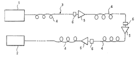
- FIG. 1 is a diagram of an optical transmission system in which a method of the invention can be implemented.
- FIG. 1 is a diagram of an optical transmission system in which a method of the invention can be implemented.
- the transmission system shown in the FIGURE comprises emitter means 1 , receiver means 2 , and a transmission line 3 which, for example, is a terrestrial transmission line and extends between said emitter and receiver means 1 and 2 .
- the emitter means 1 and the receiver means 2 include multiplexing and demultiplexing means enabling a plurality of channels to be transmitted simultaneously over the line 3 , said channels corresponding to different transmission wavelengths.
- the signals they emit and receive are advantageously signals in the form of RZ pulses, and in particular solitons.
- the line 3 comprises a plurality of optical fiber sections 4 with amplifiers 5 interposed between them.
- the line 3 includes means 6 interposed at each amplifier 5 for the purpose of measuring or deducing the power inlet to such an amplifier 5 and for returning information concerning said power to the emitter means 1 , e.g. by using an auxiliary optical channel that corresponds to a wavelength different from those of the transmission channels.
- the emitter means 1 are continuously aware of the power P ij which is the power of channel i at the inlet to amplifier j , with this applying to i lying in the range 1 to n and j lying in the range 1 to m , where n is the number of transmission channels, and where m is the number of amplifiers 5 .
- the emitter means 1 include calculation means which, for each channel i and as a function of the various powers P ij measured for said channel i at the inlet of each of the m amplifiers, determine a power level P il which ought to be applied to the inlet of the first amplifier for said channel i . Said emitter means then adjust the power they emit for said channel i so as to cause it to converge on said value.
- More refined functions can be envisaged that take account of amplifier gain or variation in noise factor as a function of wavelength.
- the values f i can be calculated by the calculation means or can be obtained by any other means, and in particular by analog means using the signals transmitted over the auxiliary channel.
- the function G can also depend on in-line powers and can include a peak-limiting function to limit non-linear effects.
- f i 1/( P i1 ⁇ P im ) 1/2
Abstract
Description
-
- K. Inoue, T. Kominato, H. Toba, IEEE Photon. Techn.
Letters 3, 718 (1991);
- K. Inoue, T. Kominato, H. Toba, IEEE Photon. Techn.
-
- Chaplyvy, Nagel, Tkach, “Equalization in amplified WDM lightwave transmission systems”, IEEE Photon. Techn. Lett. 4, 8 (1992);
- Chraplyvy, Tkach, Reichmann, Magill, Nagel, “End-to-end equalization experiments in amplified WDM lightwave systems”, IEEE Photon. Techn. Lett. 4, 428 (1993).
-
- the various points distributed along the transmission line are the inlets to amplifiers distributed along said line;
- for each channel, a reference power is continuously determined as a function of the optical powers received for said channel at a plurality of points distributed along the transmission line, said reference power being the power that ought to be received for said channel at one of the points along the transmission line, and the emitter means are controlled so as to servo-control the power at said point on said reference power;
- said point is the inlet to the first amplifier;
- for each channel i, a parameter fi is determined which is a function of the powers received at the various points of the transmission line, and the reference power is modified by replacing its preceding value with a reference value that is a function of said preceding value and also of the parameter fi;
- the new reference power is the product of the preceding reference power and a function of the parameter fi;
- the parameter fi is compared with the mean {overscore (f)} of the parameters fi as determined for the various channels;
- the parameter fi is such that:
where Pij represents the power at the jth point of the transmission line for channel i and where m is the number of points of said line; and
-
- the new reference power is the product of the preceding reference value and a product η·fi, where the parameter η is selected to avoid modifying the total power of the signals on emission.
where G is a predetermined function.
G(x)=x
f i=1/(P i1 ·P im)1/2
Claims (9)
f i=1/(P i1 ·P im)1/2
Applications Claiming Priority (4)
| Application Number | Priority Date | Filing Date | Title |
|---|---|---|---|
| FR99/13194 | 1999-10-22 | ||
| FR9913194A FR2800219B1 (en) | 1999-10-22 | 1999-10-22 | POWER ADJUSTMENT METHOD FOR WAVELENGTH MULTIPLEXING OPTICAL TRANSMISSION SYSTEM |
| PCT/FR2000/002924 WO2001029995A1 (en) | 1999-10-22 | 2000-10-20 | Power adjustment method for a wavelength division multiplexing optical transmission system |
| FRPCT/FR00/02924 | 2000-10-20 |
Publications (2)
| Publication Number | Publication Date |
|---|---|
| US20020176133A1 US20020176133A1 (en) | 2002-11-28 |
| US7127173B2 true US7127173B2 (en) | 2006-10-24 |
Family
ID=9551228
Family Applications (1)
| Application Number | Title | Priority Date | Filing Date |
|---|---|---|---|
| US10/127,804 Expired - Fee Related US7127173B2 (en) | 1999-10-22 | 2002-04-22 | Method of adjusting power for a wavelength-division multiplexed optical transmission system |
Country Status (7)
| Country | Link |
|---|---|
| US (1) | US7127173B2 (en) |
| EP (1) | EP1245087B1 (en) |
| AT (1) | ATE306152T1 (en) |
| CA (1) | CA2388690A1 (en) |
| DE (1) | DE60023037D1 (en) |
| FR (1) | FR2800219B1 (en) |
| WO (1) | WO2001029995A1 (en) |
Families Citing this family (3)
| Publication number | Priority date | Publication date | Assignee | Title |
|---|---|---|---|---|
| FR2800218B1 (en) | 1999-10-22 | 2002-01-11 | Algety Telecom | FIBER OPTIC TRANSMISSION SYSTEM USING RZ PULSES |
| FR2800219B1 (en) | 1999-10-22 | 2006-06-30 | Algety Telecom | POWER ADJUSTMENT METHOD FOR WAVELENGTH MULTIPLEXING OPTICAL TRANSMISSION SYSTEM |
| US7362923B2 (en) * | 2006-08-07 | 2008-04-22 | Northrop Grumman Corporation | Systems and methods for measuring signal phase shift caused by optical fibers |
Citations (76)
| Publication number | Priority date | Publication date | Assignee | Title |
|---|---|---|---|---|
| US4315666A (en) | 1979-03-19 | 1982-02-16 | Hicks Jr John W | Coupled communications fibers |
| US4342499A (en) | 1979-03-19 | 1982-08-03 | Hicks Jr John W | Communications tuning construction |
| US4401364A (en) | 1980-05-26 | 1983-08-30 | Kokusai Denshi Denwa Kabushiki Kaisha | Optical repeater system for optical communication |
| US4616898A (en) | 1980-03-31 | 1986-10-14 | Polaroid Corporation | Optical communication systems using raman repeaters and components therefor |
| US4699452A (en) | 1985-10-28 | 1987-10-13 | American Telephone And Telegraph Company, At&T Bell Laboratories | Optical communications system comprising Raman amplification means |
| US4728170A (en) | 1984-05-11 | 1988-03-01 | Standard Telephones And Cables Public Limited Co. | Single mode optical fibre attenuators |
| US4881790A (en) | 1988-04-25 | 1989-11-21 | American Telephone And Telegraph Company, At&T Bell Laboratories | Optical communications system comprising raman amplification means |
| US5007705A (en) | 1989-12-26 | 1991-04-16 | United Technologies Corporation | Variable optical fiber Bragg filter arrangement |
| US5039199A (en) | 1989-12-29 | 1991-08-13 | At&T Bell Laboratories | Lightwave transmission system having remotely pumped quasi-distributed amplifying fibers |
| US5050949A (en) | 1990-06-22 | 1991-09-24 | At&T Bell Laboratories | Multi-stage optical fiber amplifier |
| US5083874A (en) | 1989-04-14 | 1992-01-28 | Nippon Telegraph And Telephone Corporation | Optical repeater and optical network using the same |
| US5095519A (en) | 1990-11-30 | 1992-03-10 | At&T Bell Laboratories | Apparatus and method for producing an in-line optical fiber attenuator |
| US5191628A (en) | 1990-11-09 | 1993-03-02 | Northern Telecom Limited | Optical amplifiers |
| US5191586A (en) | 1991-07-18 | 1993-03-02 | General Instrument Corporation | Narrow band incoherent optical carrier generator |
| US5225922A (en) * | 1991-11-21 | 1993-07-06 | At&T Bell Laboratories | Optical transmission system equalizer |
| US5228105A (en) | 1987-05-04 | 1993-07-13 | Glista Andrew S | Programmable electro-optic packaging and interconnect system |
| EP0575881A1 (en) | 1992-06-22 | 1993-12-29 | Nec Corporation | Optical communication transmission system with chromatic dispersion compensation |
| US5283686A (en) | 1992-07-27 | 1994-02-01 | General Instrument Corporation, Jerrold Communications | Optical systems with grating reflector |
| US5323404A (en) | 1993-11-02 | 1994-06-21 | At&T Bell Laboratories | Optical fiber laser or amplifier including high reflectivity gratings |
| US5406411A (en) | 1993-10-14 | 1995-04-11 | Corning Incorporated | Fiber amplifier having efficient pump power utilization |
| US5473622A (en) | 1994-12-29 | 1995-12-05 | At&T Corp. | Cladding-pumped MOPA structure |
| US5500756A (en) | 1992-02-28 | 1996-03-19 | Hitachi, Ltd. | Optical fiber transmission system and supervision method of the same |
| US5530583A (en) | 1993-11-18 | 1996-06-25 | Matsushita Electric Industrial Co., Ltd. | Optical signal amplification apparatus and an optical fiber transmission system using the same |
| US5541766A (en) | 1994-11-30 | 1996-07-30 | At&T Corp. | Gain control for optically amplified systems |
| US5557442A (en) | 1993-06-04 | 1996-09-17 | Ciena Corporation | Optical amplifiers with flattened gain curves |
| US5559910A (en) | 1994-06-06 | 1996-09-24 | Kokusai Denshin Denwa Kabushiki Kaisha | Wavelength division multiplexed optical fiber transmission equiptment |
| EP0734105A2 (en) | 1995-03-20 | 1996-09-25 | Fujitsu Limited | Optical fiber amplifier and dispersion compensating fiber module for optical fiber amplifier |
| US5611016A (en) | 1996-06-07 | 1997-03-11 | Lucent Technologies Inc. | Dispersion-balanced optical cable |
| US5623508A (en) | 1996-02-12 | 1997-04-22 | Lucent Technologies Inc. | Article comprising a counter-pumped optical fiber raman amplifier |
| US5633974A (en) | 1994-09-27 | 1997-05-27 | The Whitaker Corporation | All fiber attenuator |
| US5636301A (en) | 1994-06-02 | 1997-06-03 | Northern Telecom Limited | Optical waveguide amplifiers |
| WO1997020403A1 (en) | 1995-11-27 | 1997-06-05 | British Technology Group Limited | Dispersion management system for soliton optical transmission system |
| US5651085A (en) | 1994-09-27 | 1997-07-22 | Chia; Shin-Lo | All fiber attenuator |
| US5673280A (en) | 1996-02-12 | 1997-09-30 | Lucent Technologies Inc. | Article comprising low noise optical fiber raman amplifier |
| US5675432A (en) | 1995-04-05 | 1997-10-07 | Hitachi, Ltd. | Optical amplification apparatus |
| US5694512A (en) | 1996-07-09 | 1997-12-02 | Framatome Connectors Canada Inc. | Compact tunable wavelength independent all-fiber optical attenuator and method of making same |
| US5696615A (en) | 1995-11-13 | 1997-12-09 | Ciena Corporation | Wavelength division multiplexed optical communication systems employing uniform gain optical amplifiers |
| US5717510A (en) | 1994-08-02 | 1998-02-10 | Fujitsu Limited | Optimized optical transmission system for high capacity transmission |
| US5764406A (en) | 1996-10-01 | 1998-06-09 | Corning Incorporated | Hydrid optical amplifier having improved dynamic gain tilt |
| EP0853396A2 (en) | 1996-10-21 | 1998-07-15 | Fujitsu Limited | Optical transmission system including optical repeaters with selectively enabled gain equalizers contained therein and including an add/drop apparatus with a plurality of individually selectable filters |
| US5805621A (en) | 1996-11-12 | 1998-09-08 | Lucent Technologies, Inc. | Fiber multimode laser with reduced noise |
| US5812710A (en) | 1996-02-07 | 1998-09-22 | Fujitsu Limited | Apparatus and method for optical equalization and amplification |
| WO1998042088A1 (en) | 1997-03-17 | 1998-09-24 | Sdl, Inc. | Multiple stage optical fiber amplifier |
| US5815710A (en) | 1995-03-22 | 1998-09-29 | Sun Microsystems, Inc. | Method and apparatus for managing relationships among objects in a distributed object environment |
| US5815299A (en) | 1995-09-08 | 1998-09-29 | Alcatel N.V. | Method and system for equalizing respective power levels of channels of a received optical frequency division multiplexed signal |
| US5861981A (en) | 1997-08-20 | 1999-01-19 | Ditech Corporation | Optical amplifier having dynamically shaped gain |
| WO1999007088A1 (en) | 1997-07-31 | 1999-02-11 | Btg International Ltd. | Optical fibre communication system |
| US5880866A (en) | 1996-11-13 | 1999-03-09 | At&T Corp | Time division demultiplexing using selective Raman amplification |
| US5883736A (en) | 1996-02-23 | 1999-03-16 | The Furukawa Electric Co., Ltd. | Er-doped optical fiber amplifier |
| US5892615A (en) | 1997-03-17 | 1999-04-06 | Sdl, Inc. | Output power enhancement in optical fiber lasers |
| US5900969A (en) | 1997-02-14 | 1999-05-04 | Lucent Technologies Inc. | Broadband flat gain optical amplifier |
| US5903371A (en) | 1995-10-19 | 1999-05-11 | Pirelli Cavi S.P.A. | Transparent optical self-healing-ring communication network |
| US5920423A (en) | 1997-12-05 | 1999-07-06 | Sdl, Inc. | Multiple pumped fiber amplifiers for WDM communication systems with adjustment for the amplifier signal gain bandwidth |
| US5940208A (en) | 1996-04-02 | 1999-08-17 | Corning Incorporated | Switchable fiber optic device for fiber transmission system and components thereof |
| WO1999043107A1 (en) | 1998-02-20 | 1999-08-26 | Ciena Corporation | Optical amplifier having an improved noise figure |
| US5959750A (en) | 1996-06-06 | 1999-09-28 | Lucent Technologies Inc. | Method of upgrading transmission capacity by Raman amplification |
| US5963361A (en) | 1998-05-22 | 1999-10-05 | Ciena Corporation | Optical amplifier having a variable attenuator controlled based on detected ASE |
| US5999548A (en) | 1997-06-18 | 1999-12-07 | Nippon Telegraph And Telephone Corporation | White optical pulse source and applications |
| US6031646A (en) | 1997-06-06 | 2000-02-29 | Pirelli Cavi E Sistemi S.P.A. | Optical fiber telecommunication system |
| US6040933A (en) * | 1997-12-19 | 2000-03-21 | Nortel Networks Corporation | Method and apparatus for channel equalization in wavelength division multiplexed systems |
| US6055092A (en) | 1995-03-09 | 2000-04-25 | Fujitsu Limited | Multi-wavelength light amplifier |
| US6057959A (en) | 1998-05-22 | 2000-05-02 | Ciena Corporation | Optical amplifier having substantially uniform spectral gain |
| US6081366A (en) | 1997-08-28 | 2000-06-27 | Lucent Technologies Inc. | Optical fiber communication system with a distributed Raman amplifier and a remotely pumped er-doped fiber amplifier |
| US6115174A (en) | 1998-07-21 | 2000-09-05 | Corvis Corporation | Optical signal varying devices |
| US6122298A (en) | 1996-11-01 | 2000-09-19 | Tyco Submarine Systems Ltd. | Multi-wavelength optical pump |
| US6147794A (en) | 1999-02-04 | 2000-11-14 | Lucent Technologies, Inc. | Raman amplifier with pump source for improved performance |
| US6151338A (en) | 1997-02-19 | 2000-11-21 | Sdl, Inc. | High power laser optical amplifier system |
| US6173588B1 (en) | 1996-01-11 | 2001-01-16 | Corning Incorporated | Method of making dispersion managed optical fibers |
| US6212310B1 (en) | 1996-10-22 | 2001-04-03 | Sdl, Inc. | High power fiber gain media system achieved through power scaling via multiplexing |
| WO2001029995A1 (en) | 1999-10-22 | 2001-04-26 | Corvis Algety | Power adjustment method for a wavelength division multiplexing optical transmission system |
| WO2001029994A1 (en) | 1999-10-22 | 2001-04-26 | Corvis Algety | Optical fibre transmission system using rz pulses |
| US6229935B1 (en) | 1995-12-21 | 2001-05-08 | Alcatel | Dispersion slope compensation in optical transmission systems |
| US6236498B1 (en) | 1998-02-20 | 2001-05-22 | Sdl, Inc. | Upgradable, gain flattened fiber amplifiers for WDM applications |
| US6292603B1 (en) | 1998-05-29 | 2001-09-18 | Kokusai Denshin Denwa Co., Ltd. | Dispersion compensation device |
| US6392769B1 (en) * | 1999-03-19 | 2002-05-21 | Lucent Technologies Inc. | Automatic level control circuit for optical system |
| US20030053163A1 (en) * | 1998-09-24 | 2003-03-20 | Jingui Li | Analogous channel method for performance monitoring and equalization in optical networks |
Family Cites Families (2)
| Publication number | Priority date | Publication date | Assignee | Title |
|---|---|---|---|---|
| JPH08223136A (en) * | 1995-02-15 | 1996-08-30 | Nippon Telegr & Teleph Corp <Ntt> | Gain equalizing method for optical amplifying and repeating system |
| US6172588B1 (en) * | 1999-04-23 | 2001-01-09 | General Electric Company | Apparatus and method for a superconductive magnet with pole piece |
-
1999
- 1999-10-22 FR FR9913194A patent/FR2800219B1/en not_active Expired - Fee Related
-
2000
- 2000-10-20 WO PCT/FR2000/002924 patent/WO2001029995A1/en active IP Right Grant
- 2000-10-20 CA CA002388690A patent/CA2388690A1/en not_active Abandoned
- 2000-10-20 AT AT00969658T patent/ATE306152T1/en not_active IP Right Cessation
- 2000-10-20 EP EP00969658A patent/EP1245087B1/en not_active Expired - Lifetime
- 2000-10-20 DE DE60023037T patent/DE60023037D1/en not_active Expired - Fee Related
-
2002
- 2002-04-22 US US10/127,804 patent/US7127173B2/en not_active Expired - Fee Related
Patent Citations (80)
| Publication number | Priority date | Publication date | Assignee | Title |
|---|---|---|---|---|
| US4342499A (en) | 1979-03-19 | 1982-08-03 | Hicks Jr John W | Communications tuning construction |
| US4315666A (en) | 1979-03-19 | 1982-02-16 | Hicks Jr John W | Coupled communications fibers |
| US4616898A (en) | 1980-03-31 | 1986-10-14 | Polaroid Corporation | Optical communication systems using raman repeaters and components therefor |
| US4401364A (en) | 1980-05-26 | 1983-08-30 | Kokusai Denshi Denwa Kabushiki Kaisha | Optical repeater system for optical communication |
| US4728170A (en) | 1984-05-11 | 1988-03-01 | Standard Telephones And Cables Public Limited Co. | Single mode optical fibre attenuators |
| US4699452A (en) | 1985-10-28 | 1987-10-13 | American Telephone And Telegraph Company, At&T Bell Laboratories | Optical communications system comprising Raman amplification means |
| US5228105A (en) | 1987-05-04 | 1993-07-13 | Glista Andrew S | Programmable electro-optic packaging and interconnect system |
| US4881790A (en) | 1988-04-25 | 1989-11-21 | American Telephone And Telegraph Company, At&T Bell Laboratories | Optical communications system comprising raman amplification means |
| US5083874A (en) | 1989-04-14 | 1992-01-28 | Nippon Telegraph And Telephone Corporation | Optical repeater and optical network using the same |
| US5007705A (en) | 1989-12-26 | 1991-04-16 | United Technologies Corporation | Variable optical fiber Bragg filter arrangement |
| US5039199A (en) | 1989-12-29 | 1991-08-13 | At&T Bell Laboratories | Lightwave transmission system having remotely pumped quasi-distributed amplifying fibers |
| US5050949A (en) | 1990-06-22 | 1991-09-24 | At&T Bell Laboratories | Multi-stage optical fiber amplifier |
| US5191628A (en) | 1990-11-09 | 1993-03-02 | Northern Telecom Limited | Optical amplifiers |
| US5095519A (en) | 1990-11-30 | 1992-03-10 | At&T Bell Laboratories | Apparatus and method for producing an in-line optical fiber attenuator |
| US5191586A (en) | 1991-07-18 | 1993-03-02 | General Instrument Corporation | Narrow band incoherent optical carrier generator |
| US5225922A (en) * | 1991-11-21 | 1993-07-06 | At&T Bell Laboratories | Optical transmission system equalizer |
| US5500756A (en) | 1992-02-28 | 1996-03-19 | Hitachi, Ltd. | Optical fiber transmission system and supervision method of the same |
| EP0575881A1 (en) | 1992-06-22 | 1993-12-29 | Nec Corporation | Optical communication transmission system with chromatic dispersion compensation |
| US5283686A (en) | 1992-07-27 | 1994-02-01 | General Instrument Corporation, Jerrold Communications | Optical systems with grating reflector |
| US5579143A (en) | 1993-06-04 | 1996-11-26 | Ciena Corporation | Optical system with tunable in-fiber gratings |
| US5557442A (en) | 1993-06-04 | 1996-09-17 | Ciena Corporation | Optical amplifiers with flattened gain curves |
| US5406411A (en) | 1993-10-14 | 1995-04-11 | Corning Incorporated | Fiber amplifier having efficient pump power utilization |
| US5323404A (en) | 1993-11-02 | 1994-06-21 | At&T Bell Laboratories | Optical fiber laser or amplifier including high reflectivity gratings |
| US5530583A (en) | 1993-11-18 | 1996-06-25 | Matsushita Electric Industrial Co., Ltd. | Optical signal amplification apparatus and an optical fiber transmission system using the same |
| US5636301A (en) | 1994-06-02 | 1997-06-03 | Northern Telecom Limited | Optical waveguide amplifiers |
| US5559910A (en) | 1994-06-06 | 1996-09-24 | Kokusai Denshin Denwa Kabushiki Kaisha | Wavelength division multiplexed optical fiber transmission equiptment |
| US5717510A (en) | 1994-08-02 | 1998-02-10 | Fujitsu Limited | Optimized optical transmission system for high capacity transmission |
| US5651085A (en) | 1994-09-27 | 1997-07-22 | Chia; Shin-Lo | All fiber attenuator |
| US5633974A (en) | 1994-09-27 | 1997-05-27 | The Whitaker Corporation | All fiber attenuator |
| US5541766A (en) | 1994-11-30 | 1996-07-30 | At&T Corp. | Gain control for optically amplified systems |
| US5473622A (en) | 1994-12-29 | 1995-12-05 | At&T Corp. | Cladding-pumped MOPA structure |
| US6055092A (en) | 1995-03-09 | 2000-04-25 | Fujitsu Limited | Multi-wavelength light amplifier |
| EP0734105A2 (en) | 1995-03-20 | 1996-09-25 | Fujitsu Limited | Optical fiber amplifier and dispersion compensating fiber module for optical fiber amplifier |
| US5815710A (en) | 1995-03-22 | 1998-09-29 | Sun Microsystems, Inc. | Method and apparatus for managing relationships among objects in a distributed object environment |
| US5675432A (en) | 1995-04-05 | 1997-10-07 | Hitachi, Ltd. | Optical amplification apparatus |
| US5815299A (en) | 1995-09-08 | 1998-09-29 | Alcatel N.V. | Method and system for equalizing respective power levels of channels of a received optical frequency division multiplexed signal |
| US5903371A (en) | 1995-10-19 | 1999-05-11 | Pirelli Cavi S.P.A. | Transparent optical self-healing-ring communication network |
| US5696615A (en) | 1995-11-13 | 1997-12-09 | Ciena Corporation | Wavelength division multiplexed optical communication systems employing uniform gain optical amplifiers |
| WO1997020403A1 (en) | 1995-11-27 | 1997-06-05 | British Technology Group Limited | Dispersion management system for soliton optical transmission system |
| US6229935B1 (en) | 1995-12-21 | 2001-05-08 | Alcatel | Dispersion slope compensation in optical transmission systems |
| US6173588B1 (en) | 1996-01-11 | 2001-01-16 | Corning Incorporated | Method of making dispersion managed optical fibers |
| US5812710A (en) | 1996-02-07 | 1998-09-22 | Fujitsu Limited | Apparatus and method for optical equalization and amplification |
| US5623508A (en) | 1996-02-12 | 1997-04-22 | Lucent Technologies Inc. | Article comprising a counter-pumped optical fiber raman amplifier |
| US5673280A (en) | 1996-02-12 | 1997-09-30 | Lucent Technologies Inc. | Article comprising low noise optical fiber raman amplifier |
| US5883736A (en) | 1996-02-23 | 1999-03-16 | The Furukawa Electric Co., Ltd. | Er-doped optical fiber amplifier |
| US5940208A (en) | 1996-04-02 | 1999-08-17 | Corning Incorporated | Switchable fiber optic device for fiber transmission system and components thereof |
| US5959750A (en) | 1996-06-06 | 1999-09-28 | Lucent Technologies Inc. | Method of upgrading transmission capacity by Raman amplification |
| US5611016A (en) | 1996-06-07 | 1997-03-11 | Lucent Technologies Inc. | Dispersion-balanced optical cable |
| US5694512A (en) | 1996-07-09 | 1997-12-02 | Framatome Connectors Canada Inc. | Compact tunable wavelength independent all-fiber optical attenuator and method of making same |
| US5764406A (en) | 1996-10-01 | 1998-06-09 | Corning Incorporated | Hydrid optical amplifier having improved dynamic gain tilt |
| EP0853396A2 (en) | 1996-10-21 | 1998-07-15 | Fujitsu Limited | Optical transmission system including optical repeaters with selectively enabled gain equalizers contained therein and including an add/drop apparatus with a plurality of individually selectable filters |
| US6212310B1 (en) | 1996-10-22 | 2001-04-03 | Sdl, Inc. | High power fiber gain media system achieved through power scaling via multiplexing |
| US6122298A (en) | 1996-11-01 | 2000-09-19 | Tyco Submarine Systems Ltd. | Multi-wavelength optical pump |
| US5805621A (en) | 1996-11-12 | 1998-09-08 | Lucent Technologies, Inc. | Fiber multimode laser with reduced noise |
| US5880866A (en) | 1996-11-13 | 1999-03-09 | At&T Corp | Time division demultiplexing using selective Raman amplification |
| US5900969A (en) | 1997-02-14 | 1999-05-04 | Lucent Technologies Inc. | Broadband flat gain optical amplifier |
| US6151338A (en) | 1997-02-19 | 2000-11-21 | Sdl, Inc. | High power laser optical amplifier system |
| US6118575A (en) | 1997-03-17 | 2000-09-12 | Sdl, Inc. | Optical fiber gain medium with evanescent filtering |
| US5892615A (en) | 1997-03-17 | 1999-04-06 | Sdl, Inc. | Output power enhancement in optical fiber lasers |
| US6181465B1 (en) | 1997-03-17 | 2001-01-30 | Sdl, Inc. | Optical fiber gain medium with wavelength selective core filter |
| WO1998042088A1 (en) | 1997-03-17 | 1998-09-24 | Sdl, Inc. | Multiple stage optical fiber amplifier |
| US6031646A (en) | 1997-06-06 | 2000-02-29 | Pirelli Cavi E Sistemi S.P.A. | Optical fiber telecommunication system |
| US5999548A (en) | 1997-06-18 | 1999-12-07 | Nippon Telegraph And Telephone Corporation | White optical pulse source and applications |
| WO1999007088A1 (en) | 1997-07-31 | 1999-02-11 | Btg International Ltd. | Optical fibre communication system |
| US6321015B1 (en) | 1997-07-31 | 2001-11-20 | Btg International Limited | Optical fibre communication system |
| US5861981A (en) | 1997-08-20 | 1999-01-19 | Ditech Corporation | Optical amplifier having dynamically shaped gain |
| US6081366A (en) | 1997-08-28 | 2000-06-27 | Lucent Technologies Inc. | Optical fiber communication system with a distributed Raman amplifier and a remotely pumped er-doped fiber amplifier |
| US5920423A (en) | 1997-12-05 | 1999-07-06 | Sdl, Inc. | Multiple pumped fiber amplifiers for WDM communication systems with adjustment for the amplifier signal gain bandwidth |
| US6040933A (en) * | 1997-12-19 | 2000-03-21 | Nortel Networks Corporation | Method and apparatus for channel equalization in wavelength division multiplexed systems |
| US6236498B1 (en) | 1998-02-20 | 2001-05-22 | Sdl, Inc. | Upgradable, gain flattened fiber amplifiers for WDM applications |
| WO1999043107A1 (en) | 1998-02-20 | 1999-08-26 | Ciena Corporation | Optical amplifier having an improved noise figure |
| US5963361A (en) | 1998-05-22 | 1999-10-05 | Ciena Corporation | Optical amplifier having a variable attenuator controlled based on detected ASE |
| US6057959A (en) | 1998-05-22 | 2000-05-02 | Ciena Corporation | Optical amplifier having substantially uniform spectral gain |
| US6292603B1 (en) | 1998-05-29 | 2001-09-18 | Kokusai Denshin Denwa Co., Ltd. | Dispersion compensation device |
| US6115174A (en) | 1998-07-21 | 2000-09-05 | Corvis Corporation | Optical signal varying devices |
| US20030053163A1 (en) * | 1998-09-24 | 2003-03-20 | Jingui Li | Analogous channel method for performance monitoring and equalization in optical networks |
| US6147794A (en) | 1999-02-04 | 2000-11-14 | Lucent Technologies, Inc. | Raman amplifier with pump source for improved performance |
| US6392769B1 (en) * | 1999-03-19 | 2002-05-21 | Lucent Technologies Inc. | Automatic level control circuit for optical system |
| WO2001029995A1 (en) | 1999-10-22 | 2001-04-26 | Corvis Algety | Power adjustment method for a wavelength division multiplexing optical transmission system |
| WO2001029994A1 (en) | 1999-10-22 | 2001-04-26 | Corvis Algety | Optical fibre transmission system using rz pulses |
Non-Patent Citations (25)
| Title |
|---|
| Aida, K., et al., Long-Span Repeaterless IM/DD Optical Transmission Experiment over 300 KM using Optical Amplifies, ICC '91, vol. 3, pp. 1228-1232, 1991, Published: New York, NY, USA. |
| Chernikov, S.V., et al., 10 Gbit/s Error-Free Transmission of 2-ps Pulses Over A 45-km Span Using Distributed Raman Amplification at 1300 nm, OFC' 98 Technical Digest p. 31. |
| Chraplyvy, et al., "End-to-End equalization experiments in amplified WDM lightwave systems", IEEE Photonics, Technical Letters vol. 4, No. 4, pp. 428-429, Apr. 1993. |
| Chraplyvy, et al., "Equalization in amplified WDM lightwave transmission systems", IEEE Photonics, Technical Letters vol. 4, No. 8, Aug. 1992, pp. 920-922. |
| Dianov, E.M., et al., Highly Efficient 1.3 mum Raman Amplifier, OFC' 98 Technical Digest pp. 33-34. |
| Dung, J.C., et al., Gain Flattening of Erbium Doped Fibre Amplifier Using Fibre Bragg Gratings, Electronics Letters, Mar. 19, 1998, vol. 34, No. 6., Online No. 19980446. |
| Grubb, S. G., Raman Amplifiers for Broadband Communications, OFC '98, OSA Technical Digest Series vol. 2, 1998, abstract. |
| Hansen, P.B., et al., Loss Compensation in Dispersion Compensating Fiber Modules by Raman Amplification, OFC' 98 Technical Digest pp. 20-21. |
| Jacobovitz-Veselka, G.R., et al., Single-Stage Booster Amplifier With Two 980 nm Pumps Stabilized by Fiber Gratings, Optical Amplifiers and their Applicaiton, Jun. 15-17, 1995, 1995 OSA Technical Digest Series, V18, pp. FC4-1-4/162-165. |
| Kawai, S., et al., Ultrawide 75 nm 3-dB Gain-Band Optical Amplifier Utilizing Erbium-Doped Fluoride Fiber and Raman Fiber, OFC' 98 Technical Digest pp. 32-33. |
| Kubota, Hirokazu, et al., "Partial Soliton Communication System", Optics Communications 87, (1992) p. 15-18. |
| Masuda, H., et al., Ultra-Wideband Hybrid Amplifier Comprising Distributed Raman Amplifier and Erbium-Doped Fiber Amplifier, Electronics Letters, Jun. 25, 1998, vol. 34, No. 13, Online No. 19980935. |
| Masuda, H., et al., Ultra-Wideband Optical Amplification With a 3-dB Bandwidth of 67 nm Using a Partially Gain Flattened Erbium-Doped Fiber Amplifier and Raman Amplification, Optical Amplifiers and their Application, Aug. 3-5, 1994, 1997 OSA Technical Digest Series, V20, pp. MC3-1-4/40-3. |
| Park, S.Y., et al., Feasibility Demonstration of 10 Gbit/s Channel WDM Network Using Dynamic Gain-Controlled EDFAs, Electronics Letters, Mar. 5, 1998, vol. 34, No. 5., Online No. 19980346. |
| Rottwitt, K., et al., A 92 nm Bandwidth Raman Amplifier, OFC' 98, Post-Deadline Paper PD6-1-4. |
| Rottwitt, K., et al., Detailed Analysis of Raman Amplifiers for Long-Haul Transmission, OFC' 98 Technical Digest pp. 30-31. |
| Srivastava, A. K., et al., 1 Tb/s Transmission of 100 WDM 10 Gb/s Channels Over 400 km of TrueWave Fiber, OFC' 98, Post-Deadline Paper PD10-1-4. |
| Stentz, A., et al., "Analog-Grade Power Raman Ring Amplifier at 1.3um" OSA Trends in Optics and Photonics, vol. 5, Optical Amplifiers and Their applications. From the Topical Meeting, pp. 350-368, Published: Washington, DC, USA, 1996. |
| Sugaya, Y., et al., Novel Configuration for Low-Noise and Wide-Dynamic-Range Er-Doped Fiber Amplifiers for WDM Systems, Optical Amplifiers and their Application, Jun. 15-17, 1995, 1995 OSA Technical Digest Series, V18, pp. FC3-1-4/158-161. |
| Suzuki, M., et al., "170 Gbit/s transmission over 10,850 km using large core transmission fiber", OFC' 98, Post deadline paper, pp. PD17-1-PD17-4, San Jose, California, USA. |
| Taga, H., Edagawa, N., Suzuki, M., Takeda, N., Imai, K., Yamamoto, S. and Akiba, S., "213 Gbit/s (20x10.66) over 9000km transmission experiment using dispersion-slope compensator", OFC' 98, Post deadline paper, pp. PD13-1-PD-13-4, San Jose, California, USA. |
| Takano, K., et al., An Optical Pre-Amplifier With Automatic Gain Control Function, Proceedings of the 1995 IEICE General Conference, Mar. 27-30, 1995, Fukuoka, Fukuoka Institute of Technology b-1067, p. 513. |
| Wen, Senfar, et al., "Distributed Erbium-Doped Fiber Amplifiers with Stimulated Raman Scattering", IEEE Photonics Technology Letters, Feb. 1992, vol. 4, No. 2, New York, US, pp. 189-192, IEEE Log No.: 9105789. |
| Yu, A., et al., Analysis of Optical Gain and Noise Spectral Properties of Erbium-Doped Fiber Amplifier Cascade, Optical Amplifiers and their Application, Aug. 3-5, 1994, 1994 OSA Technical Digest Series, V14, pp. FBI-1-3/124-126. |
| Zou et al., Compensation of Raman Scattering and EDFA's Nonuniform Gain in Ultra-Long-Distance WDM Links, IEEE Photonics Technology Letters, vol. 8, No. 1, Jan. 1996, pp. 139-141. |
Also Published As
| Publication number | Publication date |
|---|---|
| FR2800219B1 (en) | 2006-06-30 |
| CA2388690A1 (en) | 2001-04-26 |
| US20020176133A1 (en) | 2002-11-28 |
| WO2001029995A1 (en) | 2001-04-26 |
| DE60023037D1 (en) | 2005-11-10 |
| EP1245087A1 (en) | 2002-10-02 |
| ATE306152T1 (en) | 2005-10-15 |
| FR2800219A1 (en) | 2001-04-27 |
| EP1245087B1 (en) | 2005-10-05 |
Similar Documents
| Publication | Publication Date | Title |
|---|---|---|
| US6807376B2 (en) | Gain equalizer which includes a plurality of optical filters for equalizing the gain of an optical amplifier | |
| US6359726B1 (en) | Wavelength division multiplexing optical amplifier with function of gain-equalizing and optical communication system | |
| US6885499B1 (en) | Optical amplifying apparatus for amplifying wide-wavelength-band light, optical sending apparatus, optical transmission system, and optical amplifying method | |
| US6934479B2 (en) | Wavelength division multiplexing optical communication system and wavelength division multiplexing optical communication method | |
| JP2834376B2 (en) | Signal processing device | |
| US6724526B1 (en) | Inter-wavelength light power deviation monitoring method and optical equalizer and optical amplifier utilizing the method | |
| JP5239141B2 (en) | Optical amplification device and control method thereof | |
| JPH11121848A (en) | Optical amplifier and optical transmission system provided with the light amplifier | |
| US7715092B2 (en) | Dynamic raman tilt compensation | |
| US6411429B1 (en) | Optical amplifying apparatus, wide-band optical amplifying apparatus, and optical communication system | |
| JP2001024592A (en) | Optical amplifier | |
| JP3771010B2 (en) | Method for optical amplification and system for implementing the method | |
| JP2003524931A (en) | Multi-wavelength optical communication system with optical amplifier | |
| Giles et al. | Dynamic gain equalization in two-stage fiber amplifiers | |
| US20030021008A1 (en) | System and method for controlling noise figure | |
| US7127173B2 (en) | Method of adjusting power for a wavelength-division multiplexed optical transmission system | |
| JPH0943647A (en) | Gain equalizer and light amplifier | |
| WO2003079584A1 (en) | Method and system for optical fiber transmission using raman amplification | |
| EP0933888A2 (en) | Optical gain equalization unit, optical gain equalization method, and optical fiber transmission line | |
| JP4361506B2 (en) | Wavelength multiplexing optical repeater system | |
| US7042632B2 (en) | Raman amplifier | |
| US6268955B1 (en) | Optical amplifier and wave length division multiplexed light transmission system | |
| US8681420B2 (en) | Optical transmission system | |
| JP2009164565A (en) | Gain equalizer, optical amplifier, and optical amplification method | |
| JP3338007B2 (en) | Optical amplifier and WDM optical communication system |
Legal Events
| Date | Code | Title | Description |
|---|---|---|---|
| AS | Assignment |
Owner name: CORVIS ALGETY SA, FRANCE Free format text: ASSIGNMENT OF ASSIGNORS INTEREST;ASSIGNOR:GEORGES, THIERRY;REEL/FRAME:013135/0023 Effective date: 20020514 |
|
| CC | Certificate of correction | ||
| FPAY | Fee payment |
Year of fee payment: 4 |
|
| AS | Assignment |
Owner name: LEVEL 3 COMMUNICATIONS, LLC, COLORADO Free format text: ASSIGNMENT OF ASSIGNORS INTEREST;ASSIGNOR:BROADWING, LLC;REEL/FRAME:026533/0440 Effective date: 20110630 |
|
| FPAY | Fee payment |
Year of fee payment: 8 |
|
| FEPP | Fee payment procedure |
Free format text: MAINTENANCE FEE REMINDER MAILED (ORIGINAL EVENT CODE: REM.) |
|
| LAPS | Lapse for failure to pay maintenance fees |
Free format text: PATENT EXPIRED FOR FAILURE TO PAY MAINTENANCE FEES (ORIGINAL EVENT CODE: EXP.); ENTITY STATUS OF PATENT OWNER: LARGE ENTITY |
|
| STCH | Information on status: patent discontinuation |
Free format text: PATENT EXPIRED DUE TO NONPAYMENT OF MAINTENANCE FEES UNDER 37 CFR 1.362 |
|
| FP | Lapsed due to failure to pay maintenance fee |
Effective date: 20181024 |
|
| AS | Assignment |
Owner name: OPTIC153 LLC, DELAWARE Free format text: ASSIGNMENT OF ASSIGNORS INTEREST;ASSIGNOR:LEVEL 3 COMMUNICATIONS, LLC;REEL/FRAME:056469/0773 Effective date: 20170411 |