US7126368B2 - System and method for detecting motor coil-to-coil faults - Google Patents
System and method for detecting motor coil-to-coil faults Download PDFInfo
- Publication number
- US7126368B2 US7126368B2 US10/942,269 US94226904A US7126368B2 US 7126368 B2 US7126368 B2 US 7126368B2 US 94226904 A US94226904 A US 94226904A US 7126368 B2 US7126368 B2 US 7126368B2
- Authority
- US
- United States
- Prior art keywords
- coil
- motor
- coils
- control unit
- output
- Prior art date
- Legal status (The legal status is an assumption and is not a legal conclusion. Google has not performed a legal analysis and makes no representation as to the accuracy of the status listed.)
- Active
Links
Images


Classifications
-
- G—PHYSICS
- G01—MEASURING; TESTING
- G01R—MEASURING ELECTRIC VARIABLES; MEASURING MAGNETIC VARIABLES
- G01R31/00—Arrangements for testing electric properties; Arrangements for locating electric faults; Arrangements for electrical testing characterised by what is being tested not provided for elsewhere
- G01R31/34—Testing dynamo-electric machines
- G01R31/343—Testing dynamo-electric machines in operation
-
- H—ELECTRICITY
- H02—GENERATION; CONVERSION OR DISTRIBUTION OF ELECTRIC POWER
- H02H—EMERGENCY PROTECTIVE CIRCUIT ARRANGEMENTS
- H02H11/00—Emergency protective circuit arrangements for preventing the switching-on in case an undesired electric working condition might result
- H02H11/005—Emergency protective circuit arrangements for preventing the switching-on in case an undesired electric working condition might result in case of too low isolation resistance, too high load, short-circuit; earth fault
-
- H—ELECTRICITY
- H02—GENERATION; CONVERSION OR DISTRIBUTION OF ELECTRIC POWER
- H02H—EMERGENCY PROTECTIVE CIRCUIT ARRANGEMENTS
- H02H7/00—Emergency protective circuit arrangements specially adapted for specific types of electric machines or apparatus or for sectionalised protection of cable or line systems, and effecting automatic switching in the event of an undesired change from normal working conditions
- H02H7/08—Emergency protective circuit arrangements specially adapted for specific types of electric machines or apparatus or for sectionalised protection of cable or line systems, and effecting automatic switching in the event of an undesired change from normal working conditions for dynamo-electric motors
- H02H7/0833—Emergency protective circuit arrangements specially adapted for specific types of electric machines or apparatus or for sectionalised protection of cable or line systems, and effecting automatic switching in the event of an undesired change from normal working conditions for dynamo-electric motors for electric motors with control arrangements
Definitions
- the present invention relates to a system and method for detecting faults in an electric motor.
- Small, low cost electric motors and controllers are used in certain product applications, such as electric reel drives on greens mowers which includes a 3-phase permanent magnet brushless DC electric motor.
- the motor controller typically includes high power FETs which can be damaged by overheating or overcurrents. It is difficult to detect when such a motor fails, and when a system with such a failed motor is not working, a repair technician may attempt to repair the system by replacing the controller instead of the faulty motor. But, if the motor was faulty, it may merely damage the new controller. Thus, it is desired to have a means for detecting motor faults before the faulty motor can damage a controller.
- an object of this invention is to provide a simple and inexpensive system for detecting faults in an electric motor.
- Another object of this invention is to provide a system for detecting phase coil-to-phase coil faults in an electric motor.
- Another object of this invention is to provide a system for detecting faults in an electric motor before the faulty motor can damage a controller.
- a system and method upon start-up, detects coil-to-coil faults in an electric motor having a plurality of coils.
- the method includes applying a square wave signal to a first coil of the motor, connecting a second coil to ground, connecting a capacitor and a resistor between ground potential and a third coil of the motor, applying the third coil output voltage to an amplifying and peak detecting circuit, applying an output of the amplifying and peak detecting circuit to the input of the control unit and, after a delay period, generating a motor fault signal if the output of the amplifying and peak detecting circuit is below a predetermined threshold.
- the square wave signal is amplified by a circuit which prevents transmission of voltage signals from the coils to the output of the control unit during normal operation of the motor.
- FIG. 1 is a schematic diagram of a motor fault detection system according to the present invention
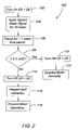
- FIG. 2 is logic flow diagram illustrating an algorithm executed by the ECU of FIG. 1 .
- the motor fault detection system 10 is connected to a conventional 3-phase brushless DC motor 12 which has phase coils 14 , 16 and 18 .
- the motor fault detection system 10 includes a microprocessor-based electronic control unit (ECU) 20 which supplies a square wave excitation signal to a driver/current amplifier 22 .
- ECU electronice control unit
- Driver/amplifier 22 includes resistors R 6 and R 7 , each connected between the output of ECU 20 and a base of a transistor Q 1 and Q 2 , respectively.
- the emitter of transistor Q 1 is connected to a supply voltage, Vcc, such as +5 volts.
- the collector of Q 1 is connected to the base of transistor Q 3 and to the collector of transistor Q 2 via resistor R 5 .
- the collector of transistor Q 2 is also connected to the base of transistor Q 4 .
- the emitters of Q 2 and Q 4 are connected to ground.
- the emitter of transistor Q 3 is connected to a supply voltage, such as +5 volts.
- the collector of Q 3 is connected to the anode of diode D 2 .
- the cathode of diode D 2 is connected to the collector of transistor Q 4 .
- the collector of transistor Q 4 is connected to phase coil 14 of motor 12 .
- Driver/amplifier 22 prevents transmission of voltage signals from the motor 12 to the control unit 20 during normal operation of motor 12 .
- a novel feature of the design of the driver/amplifier 22 is the inherent prevention of the “shoot-through” condition, where Q 3 and Q 4 are both conducting causing large currents and damage to Q 3 and Q 4 .
- This “shoot-through” condition can typically occur during the transition between driving a 0 volt output and a 5 volt output.
- transistor Q 1 When the ECU 20 applies a 0 volt input, transistor Q 1 is designed to be in saturation and transistor Q 2 is off. As the ECU 20 increases the input voltage to the driver 22 from 0 volts to 5 volts, transistor Q 2 is designed to be in saturation while Q 1 remains in saturation. The current through the collectors of transistors Q 1 and Q 2 is limited by R 5 so no damage occurs.
- transistors Q 1 and Q 2 when both transistors Q 1 and Q 2 are in saturation, transistors Q 3 and Q 4 will be turned off, thereby adding “dead-time” where neither transistor is on and eliminating the shoot-through condition.
- transistor Q 1 increases the input voltage to driver 22 to 5 volts, transistor Q 1 turns off, allowing transistor Q 2 to draw current out of the base of transistor Q 3 , putting it into saturation.
- the other end of coil 14 is connected to an end of coils 16 and 18 in a Y connected motor.
- the other end of coil 18 is connected to ground via normally open switch 30 which includes transistor Q 6 which is preferably part of the inverter (not shown) which supplies electrical power to the coils 14 – 18 .
- Switch 30 is opened and closed by a signal provided from an output of ECU 20 .
- coil 16 is connected to the collector of normally off or open transistor switch Q 5 via parallel connected capacitor C 1 and resistor R 4 .
- the emitter of transistor Q 5 is connected to ground and the base of transistor Q 5 is connected to a control output of ECU 20 through a resister R 8 .
- This other end of coil 16 is also connected to sense peak detector/amplifier circuit 24 .
- Circuit 24 includes a operational amplifier 26 with a + input connected to coil 16 (and resistor R 4 and capacitor C 1 ) and a ⁇ input connected to ground via resistor R 2 .
- the output of op amp 26 is connected to the anode of diode D 2 .
- the cathode of diode D 2 is connected the ⁇ input of op amp 26 via resistor R 1 , to an input of ECU 20 via resistor R 3 and to ground via resistor R 3 and capacitor C 2 .
- Circuit 24 amplifies the signal from coil 16 and generates a slowly varying DC output signal, the voltage of which varies as the peak voltage of the signal from coil 16 varies. This output signal is applied to an input of the ECU 20 .
- a microprocessor (not shown) of ECU 20 executes an algorithm 100 represented by FIG. 2 .
- the conversion of the above flow chart into a standard language for implementing the algorithm described by the flow chart in a digital computer or microprocessor, will be evident to one with ordinary skill in the art.
- Step 102 in response to a startup signal, turns on transistor switches Q 5 and Q 6 , thereby connecting the output end of coil 16 to ground via resistor R 4 and capacitor C 1 , and connecting an end of coil 18 to ground via Q 6 .
- the ECU 20 applies a square wave signal to the input of driver/amplifier 22 .
- the square wave has a 7 kHz frequency, a 50% duty cycle, a duration of about 10 milliseconds and voltage levels of zero and 5 volts.
- the optimum frequency of the square wave excitation signal may be determined based on an empirical and statistical analysis of many motors to characterize their inductance and resistance. These along with the resistor R 4 and capacitor C 1 determine the resonant frequency of an inductor-capacitor-resistor circuit.
- the frequency of the square wave signal is chosen to be the same as the resonant frequency of this circuit so that a maximum output signal will be generated by a motor with good phase-to-phase inductance.
- the current amplitude from the driver circuit 22 also affects the perceived inductance in the motor 12 (because of all the magnets, ferrous materials and magnetic field interactions), so testing is preferably done with the circuit planned to be used in the final product.
- This square wave signal is amplified by amplifier 22 and is applied to coil 14 of motor 12 .
- Amplifier 22 preferably generates a drive signal with a maximum drive current of 50 milliamps RMS and a drive voltage of between a maximum of 4 volts and a minimum drive of 0 volts. These values are application specific and can vary based on the winding inductance and resistance of the motor.
- step 106 causes the system to pause for a time period (such as about 1 millisecond) sufficient for the response to the drive signal to stabilize the voltage across capacitor C 2 .
- step 108 the ECU 20 compares the output of amplifier 24 to a threshold voltage, such as 0.5 volts, and if the output of amplifier 24 is greater than the threshold voltage, step 108 directs the algorithm to step 110 which turns off transistors Q 5 and Q 6 , and then to step 112 which ends the test algorithm 100 and allows the motor 12 to be operated normally. If the output of amplifier 24 is not greater than the threshold voltage, then step 108 directs control to step 114 which turns off transistors Q 5 and Q 6 . Then step 116 generates a fault indication signal, such as an audible signal from a speaker (not shown) and/or visible signal from a display device (not shown).
- a fault indication signal such as an audible signal from a speaker (not shown) and/or visible signal from a display device (not shown).
- step 118 prevents further operation of the motor 12 .
- steps 102 – 118 would be applied to each of the motor coils 14 – 18 , one after the other by re-arranging the connections between the driver 22 , the peak detector 24 including resister R 4 and capacitor C 1 , the switch 30 and the motor 12 .
- the result is a simple low cost system and method which detects phase inductance and phase-to-phase faults prior to normal operation of the motor.
Abstract
Description
Claims (12)
Priority Applications (2)
| Application Number | Priority Date | Filing Date | Title |
|---|---|---|---|
| US10/942,269 US7126368B2 (en) | 2004-09-16 | 2004-09-16 | System and method for detecting motor coil-to-coil faults |
| EP05108335A EP1638183A1 (en) | 2004-09-16 | 2005-09-12 | System for detecting motor coil-to-coil faults |
Applications Claiming Priority (1)
| Application Number | Priority Date | Filing Date | Title |
|---|---|---|---|
| US10/942,269 US7126368B2 (en) | 2004-09-16 | 2004-09-16 | System and method for detecting motor coil-to-coil faults |
Publications (2)
| Publication Number | Publication Date |
|---|---|
| US20060055419A1 US20060055419A1 (en) | 2006-03-16 |
| US7126368B2 true US7126368B2 (en) | 2006-10-24 |
Family
ID=35478939
Family Applications (1)
| Application Number | Title | Priority Date | Filing Date |
|---|---|---|---|
| US10/942,269 Active US7126368B2 (en) | 2004-09-16 | 2004-09-16 | System and method for detecting motor coil-to-coil faults |
Country Status (2)
| Country | Link |
|---|---|
| US (1) | US7126368B2 (en) |
| EP (1) | EP1638183A1 (en) |
Cited By (2)
| Publication number | Priority date | Publication date | Assignee | Title |
|---|---|---|---|---|
| US20090132126A1 (en) * | 2007-11-20 | 2009-05-21 | Jtekt Corporation | Electric power steering device |
| US20120112771A1 (en) * | 2010-11-05 | 2012-05-10 | Paul Schliebe | Apparatus and method for detection of solenoid current |
Families Citing this family (4)
| Publication number | Priority date | Publication date | Assignee | Title |
|---|---|---|---|---|
| US7834573B2 (en) * | 2007-07-31 | 2010-11-16 | Caterpillar Inc | Winding fault detection system |
| AT517437B1 (en) * | 2015-06-17 | 2018-06-15 | Omicron Electronics Gmbh | Test apparatus and method for operating a test apparatus |
| US10141735B2 (en) | 2016-06-27 | 2018-11-27 | Semiconductor Components Industries, Llc | Power conversion circuit with indicator coupled to input terminal to signal condition of the controller |
| CN111123095B (en) * | 2018-10-31 | 2022-09-27 | 佛山市顺德区美的电热电器制造有限公司 | Detection circuit, motor detection method, motor and household appliance |
Citations (19)
| Publication number | Priority date | Publication date | Assignee | Title |
|---|---|---|---|---|
| US4286303A (en) | 1979-03-19 | 1981-08-25 | Franklin Electric Co., Inc. | Protection system for an electric motor |
| US4541029A (en) | 1982-10-06 | 1985-09-10 | Tsubakimoto Chain Co. | Over-load and light-load protection for electric machinery |
| US5081404A (en) | 1990-11-16 | 1992-01-14 | Delco Electronics Corporation | Motor driver interface fault detection circuit with dual mode fault detection |
| US5471135A (en) * | 1994-10-20 | 1995-11-28 | Jagger; Eric | Tester and method for testing a rectifier-regulator |
| US5569966A (en) * | 1994-06-10 | 1996-10-29 | Northrop Grumman Corporation | Electric vehicle propulsion system power bridge with built-in test |
| US5652525A (en) * | 1992-03-16 | 1997-07-29 | Lockheed Martin Tactical Systems, Inc. | System and method for detecting D.C. motor circuit failures |
| US5969919A (en) | 1997-09-16 | 1999-10-19 | Honda Giken Kogyo Kabushiki Kaisha | Drive unit for electric motor |
| US6020695A (en) * | 1999-02-19 | 2000-02-01 | Vtc Inc. | Three-phase generator boost circuit |
| US6042513A (en) | 1997-03-27 | 2000-03-28 | Minarik Corporation | Non destructive runaway protection for an electric motor |
| US6291987B1 (en) * | 1999-10-28 | 2001-09-18 | General Electric Company | Method and system for detecting incipient failures in a power inverter |
| US6335631B2 (en) * | 1998-12-07 | 2002-01-01 | General Electric Company | Induction machine asymmetry detection instrument and method |
| US6381110B1 (en) | 2000-03-06 | 2002-04-30 | General Motors Corporation | Method and apparatus for detecting isolation faults in motor/inverter systems |
| US6486626B1 (en) * | 1998-10-21 | 2002-11-26 | Elliott Industries Limited | Apparatus and a method for controlling an electric vehicle |
| US6529135B1 (en) | 1999-10-12 | 2003-03-04 | Csi Technology, Inc. | Integrated electric motor monitor |
| US6590362B2 (en) | 2001-07-27 | 2003-07-08 | Texas A&M University System | Method and system for early detection of incipient faults in electric motors |
| US6611771B1 (en) | 2000-10-04 | 2003-08-26 | Eaton Corporation | Method and apparatus to detect a stator turn fault in an AC motor |
| US6628485B1 (en) * | 1999-06-17 | 2003-09-30 | Abb Research Ltd | Apparatus for limiting an electrical current |
| US6720749B2 (en) * | 2001-10-04 | 2004-04-13 | Texas Instruments Incorporated | Three-phase motor protector apparatus |
| US6784687B2 (en) * | 2002-06-10 | 2004-08-31 | Alps Electric Co., Ltd. | Diagnostic device for electric mechanism drive circuits |
Family Cites Families (2)
| Publication number | Priority date | Publication date | Assignee | Title |
|---|---|---|---|---|
| US4319297A (en) * | 1980-02-07 | 1982-03-09 | Arie Lapsker | Low winding resistance protective device |
| US5687049A (en) * | 1996-01-26 | 1997-11-11 | International Rectifier Corporation | Method and circuit for protecting power circuits against short circuit and over current faults |
-
2004
- 2004-09-16 US US10/942,269 patent/US7126368B2/en active Active
-
2005
- 2005-09-12 EP EP05108335A patent/EP1638183A1/en not_active Withdrawn
Patent Citations (19)
| Publication number | Priority date | Publication date | Assignee | Title |
|---|---|---|---|---|
| US4286303A (en) | 1979-03-19 | 1981-08-25 | Franklin Electric Co., Inc. | Protection system for an electric motor |
| US4541029A (en) | 1982-10-06 | 1985-09-10 | Tsubakimoto Chain Co. | Over-load and light-load protection for electric machinery |
| US5081404A (en) | 1990-11-16 | 1992-01-14 | Delco Electronics Corporation | Motor driver interface fault detection circuit with dual mode fault detection |
| US5652525A (en) * | 1992-03-16 | 1997-07-29 | Lockheed Martin Tactical Systems, Inc. | System and method for detecting D.C. motor circuit failures |
| US5569966A (en) * | 1994-06-10 | 1996-10-29 | Northrop Grumman Corporation | Electric vehicle propulsion system power bridge with built-in test |
| US5471135A (en) * | 1994-10-20 | 1995-11-28 | Jagger; Eric | Tester and method for testing a rectifier-regulator |
| US6042513A (en) | 1997-03-27 | 2000-03-28 | Minarik Corporation | Non destructive runaway protection for an electric motor |
| US5969919A (en) | 1997-09-16 | 1999-10-19 | Honda Giken Kogyo Kabushiki Kaisha | Drive unit for electric motor |
| US6486626B1 (en) * | 1998-10-21 | 2002-11-26 | Elliott Industries Limited | Apparatus and a method for controlling an electric vehicle |
| US6335631B2 (en) * | 1998-12-07 | 2002-01-01 | General Electric Company | Induction machine asymmetry detection instrument and method |
| US6020695A (en) * | 1999-02-19 | 2000-02-01 | Vtc Inc. | Three-phase generator boost circuit |
| US6628485B1 (en) * | 1999-06-17 | 2003-09-30 | Abb Research Ltd | Apparatus for limiting an electrical current |
| US6529135B1 (en) | 1999-10-12 | 2003-03-04 | Csi Technology, Inc. | Integrated electric motor monitor |
| US6291987B1 (en) * | 1999-10-28 | 2001-09-18 | General Electric Company | Method and system for detecting incipient failures in a power inverter |
| US6381110B1 (en) | 2000-03-06 | 2002-04-30 | General Motors Corporation | Method and apparatus for detecting isolation faults in motor/inverter systems |
| US6611771B1 (en) | 2000-10-04 | 2003-08-26 | Eaton Corporation | Method and apparatus to detect a stator turn fault in an AC motor |
| US6590362B2 (en) | 2001-07-27 | 2003-07-08 | Texas A&M University System | Method and system for early detection of incipient faults in electric motors |
| US6720749B2 (en) * | 2001-10-04 | 2004-04-13 | Texas Instruments Incorporated | Three-phase motor protector apparatus |
| US6784687B2 (en) * | 2002-06-10 | 2004-08-31 | Alps Electric Co., Ltd. | Diagnostic device for electric mechanism drive circuits |
Non-Patent Citations (1)
| Title |
|---|
| BJM Corporation, All-Test III(TM) Motor, Coil and Winding Tester, 2 pages, date unknown. |
Cited By (4)
| Publication number | Priority date | Publication date | Assignee | Title |
|---|---|---|---|---|
| US20090132126A1 (en) * | 2007-11-20 | 2009-05-21 | Jtekt Corporation | Electric power steering device |
| US8160777B2 (en) * | 2007-11-20 | 2012-04-17 | Jtekt Corporation | Electric power steering device |
| US20120112771A1 (en) * | 2010-11-05 | 2012-05-10 | Paul Schliebe | Apparatus and method for detection of solenoid current |
| US9778310B2 (en) * | 2010-11-05 | 2017-10-03 | Kelsey-Hayes Company | Apparatus and method for detection of solenoid current |
Also Published As
| Publication number | Publication date |
|---|---|
| US20060055419A1 (en) | 2006-03-16 |
| EP1638183A1 (en) | 2006-03-22 |
Similar Documents
| Publication | Publication Date | Title |
|---|---|---|
| EP1638183A1 (en) | System for detecting motor coil-to-coil faults | |
| US10374532B2 (en) | Apparatus, system and method of fault diagnosis for permanent magnet motor | |
| KR960003064A (en) | Control device and error detection method of brushless motor and air conditioner using the same | |
| EP2852847A1 (en) | Method and controller for an electric motor with fault detection | |
| JPH04504942A (en) | Dual current sensing driver circuit | |
| US9391551B2 (en) | Apparatus to detect the zero-cross of the BEMF of a three-phase electric motor and related method | |
| US8373960B2 (en) | Driving circuit for AC contactor | |
| EP2846447A2 (en) | Dead-time minimization in PWM driven power converters | |
| US7027315B2 (en) | Circuit arrangement for operating an electrical machine | |
| CN109314485B (en) | Motor driving device | |
| JP2003009574A (en) | Current-limiter circuit for brushless dc fan motor | |
| KR20070074144A (en) | Control device for brushless dc motor and control method thereof | |
| JPS61240890A (en) | Control circuit for variable magnetic reluctance motor | |
| US20090001916A1 (en) | Motor controlling device and method tehreof | |
| US10479402B2 (en) | Method for supplying an inductive load | |
| US7737762B2 (en) | Solid-state switch | |
| CN116609628A (en) | IGBT fault detection circuit and method and electric equipment | |
| US5939850A (en) | Circuit for driving polyphase motor | |
| JP2000287479A (en) | Controller for brushless motor | |
| Kim et al. | Online detection of irreversible demagnetization fault with non-excited phase voltage in brushless dc motor drive system | |
| JP6012211B2 (en) | Motor drive device and air conditioner equipped with the same | |
| US7554301B2 (en) | Fault current limiting in an electrical power network | |
| US10749455B2 (en) | Method for current control and corresponding system and apparatus | |
| US7514891B2 (en) | Method and arrangement for monitoring a power output stage | |
| GB2247999A (en) | Brushless DC motor monitor |
Legal Events
| Date | Code | Title | Description |
|---|---|---|---|
| AS | Assignment |
Owner name: DEERE & COMPANY, ILLINOIS Free format text: ASSIGNMENT OF ASSIGNORS INTEREST;ASSIGNORS:PAULSON, JOHN DAVID;BOESHANS, BRIAN FREDERICK;HOPMAN, JEFFREY GERALD;AND OTHERS;REEL/FRAME:015804/0298 Effective date: 20040630 |
|
| STCF | Information on status: patent grant |
Free format text: PATENTED CASE |
|
| FPAY | Fee payment |
Year of fee payment: 4 |
|
| FPAY | Fee payment |
Year of fee payment: 8 |
|
| MAFP | Maintenance fee payment |
Free format text: PAYMENT OF MAINTENANCE FEE, 12TH YEAR, LARGE ENTITY (ORIGINAL EVENT CODE: M1553) Year of fee payment: 12 |