US7118662B2 - Electrophoresis apparatus - Google Patents
Electrophoresis apparatus Download PDFInfo
- Publication number
- US7118662B2 US7118662B2 US10/041,597 US4159702A US7118662B2 US 7118662 B2 US7118662 B2 US 7118662B2 US 4159702 A US4159702 A US 4159702A US 7118662 B2 US7118662 B2 US 7118662B2
- Authority
- US
- United States
- Prior art keywords
- planar plate
- channel
- window
- transmission path
- electrophoresis apparatus
- Prior art date
- Legal status (The legal status is an assumption and is not a legal conclusion. Google has not performed a legal analysis and makes no representation as to the accuracy of the status listed.)
- Expired - Lifetime, expires
Links
Images


Classifications
-
- G—PHYSICS
- G01—MEASURING; TESTING
- G01N—INVESTIGATING OR ANALYSING MATERIALS BY DETERMINING THEIR CHEMICAL OR PHYSICAL PROPERTIES
- G01N27/00—Investigating or analysing materials by the use of electric, electrochemical, or magnetic means
- G01N27/26—Investigating or analysing materials by the use of electric, electrochemical, or magnetic means by investigating electrochemical variables; by using electrolysis or electrophoresis
- G01N27/416—Systems
- G01N27/447—Systems using electrophoresis
- G01N27/44704—Details; Accessories
- G01N27/44717—Arrangements for investigating the separated zones, e.g. localising zones
- G01N27/44721—Arrangements for investigating the separated zones, e.g. localising zones by optical means
-
- G—PHYSICS
- G01—MEASURING; TESTING
- G01N—INVESTIGATING OR ANALYSING MATERIALS BY DETERMINING THEIR CHEMICAL OR PHYSICAL PROPERTIES
- G01N27/00—Investigating or analysing materials by the use of electric, electrochemical, or magnetic means
- G01N27/26—Investigating or analysing materials by the use of electric, electrochemical, or magnetic means by investigating electrochemical variables; by using electrolysis or electrophoresis
- G01N27/416—Systems
- G01N27/447—Systems using electrophoresis
- G01N27/44756—Apparatus specially adapted therefor
- G01N27/44791—Microapparatus
Definitions
- the present invention relates to an electrophoresis apparatus adapted to be used for analyzing protein, peptide, amino acid, neurotransmitter, hormone nucleic acid or the like which is contained in organisms, or a trace substance contained in the environment, foods, chemical or the like.
- the above-mentioned device of prior art is operated as follows: a high voltage is applied between the electrodes inserted in the solution reservoirs at opposite ends of the sample channel so as to introduce a sample into a channel crossing part between the sample channel and the associated separation channel. Then, a voltage is applied between the electrodes inserted in the solution reservoirs at opposite end of the separation channel so as to extract only a sample located in the channel crossing part, into the separation channel where the electrophoresis of the sample is carried.
- the sample which is a mixed solution composed of several components, the components are separated from one another with the use of differences among electrophoretic speeds which are caused by their different charge states and different interactions with respect to a separating medium solution.
- a laser beam is irradiated onto the separation channel from a position above the planar glass plates. Excited light from the sample in the separation channel is detected by a detector which is arranged, coaxial with the laser beam, above the planar glass plates.
- the above-mentioned channels are arranged in a planar plate in parallel with one another in the form of an array, and several examinations can be once made by scanning the channels with the leaser beam.
- an electrophoresis substrate is made of a very thin planer glass plate having a thickness of about 0.2 to 0.3 mm. Accordingly, the incoming light and the outgoing light are limited in a direction orthogonal to the planar plate. Further, the channels are usually formed by etching with the use of fluorinated acid. Accordingly, the bottoms of the channels cannot be safely said to be flat and smooth. Accordingly, the irradiation of a beam and the detection of fluorescence are usually carried out in one and the same direction above the planar plate. Due to such a limitation caused by the optical system, there have been raised such problems of deteriorating the S/N ratio caused by background light such as scattered light or stray light, and lowering the accuracy of detection.
- a first object of the present invention is to provide an electrophoresis apparatus which can reduce affection by background light or stray light so as to enhance the accuracy of detection.
- a second object of the present invention is to provide an electrophoresis apparatus which can easily analyze samples from several specimens at a high speed.
- an electrophoresis apparatus comprising a planar plate formed therein with a channel for electrophoretic separation, a light irradiating means for irradiating an excitation beam into a detection part formed in a part of the channel, a fluorescence detecting means for detecting a degree of fluorescence which is generated from a sample by the excitation beam, the channel having a rectangular cross-sectional shape and being composed of a top surface and a bottom surface which are parallel with the surface of the planar plate, and left and right side wall surfaces, a first incoming window which is flat and smooth and which is formed in the bottom surface of the channel in the detecting part, for introducing the excitation into the channel, a second flat and smooth incoming window which is formed on a surface of the planar plate which is opposed to the first incoming window, an excitation transmission path formed between the first and second incoming windows, a first outgoing window formed in one of the side wall surfaces of the channel and
- an electrophoresis apparatus comprising a plurality of flat plates each formed therein with a capillary channel and each having the same configuration as the above-mentioned planar plate, which are layered one upon another so that the channels in the planar plates are overlapped with one another, a light beam irradiating means for irradiating a single excitation beam, which is provided at a position where the light beam goes through the capillary channels in the plurality of planar plates, at the same time, and fluorescence detecting means located at positions in extension of outgoing windows formed in side surfaces of the planar plates.
- FIG. 1 is a perspective view illustrating an embodiment of the present invention
- FIG. 2 is a perspective view for explaining a method of manufacturing an electrophoresis substrate shown in FIG. 1 ;
- FIG. 3 is a sectional view illustrating a separation channel which is formed by etching a glass pane and which is in such a condition that an excitation beam is irradiated onto the separation channel;
- FIG. 4 is a view for explaining conditions in one embodiment of the manufacturing method:
- FIG. 5 is an enlarged view illustrating another example of the separation channel in a part around a detection part
- FIG. 6 is a perspective view illustrating a variant form of the embodiment of the present invention.
- FIG. 7 is a perspective view illustrating another variant form of the embodiment of the present invention.
- FIG. 8 is a perspective view illustrating the configuration of an example of the electrophoresis apparatus in its entirety.
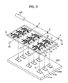
- FIG. 9 is a perspective view illustrating a further variant form of the present invention.
- FIG. 1 is a perspective view illustrating a channel substrate in an electrophoresis apparatus in an embodiment of the present invention
- a planar plate 10 is formed therein with sample channels 20 , a separation channel 21 , solution reservoirs 30 , a sample reservoir 34 and the like.
- a detecting part 21 b is formed, intermediate of the separation channel 21 .
- the separation channel 21 has a bottom part formed therein with an incoming window through which a light beam can be readily introduced into the detecting part 21 b from an excitation light source 900 .
- One side wall of the separation channel 21 is formed therein with a first smooth outgoing window 5 a through which light can readily be led into the planar plate 10 , and a fluorescence transmission path 6 b for transmitting fluorescence toward one side of the planar plate 10 while preventing the fluorescence from leaking is extended from the first outgoing window 5 a to the one side of the planar plate 10 , and is terminated with its output part at one side of the planar plate 10 , where a second smooth outgoing window 5 b is formed. Further, a fluorescence detector 910 is arranged on the outside of the second outgoing window 5 b.
- the windows 5 a , 5 b are configured so that the thickness of the upper and lower parts of the substrate formed therein with the channels becomes thinner in these parts than in other parts.
- An air space is defined in the vicinity of the one side wall of the channel within a part where the first outgoing window 5 a is formed, so as to serve as a window, and the second outgoing window 5 b has a shape such as to be recessed inward from the one side wall of the planar plate 10 , in comparison with the other part thereof.
- the fluorescence transmission path 6 b is also formed on opposite sides with air spaces. It is noted that a rod-like fiber or the like may be embedded in the planar plate 10 , on the outgoing side of the planar plate 10 at the time of forming the separation channel 21 and the like.
- the solution reservoirs 30 and the sample reservoir 34 are inserted therein with electrodes, that is, first and second sample introducing electrodes 71 , 72 , and third and fourth sample separating electrodes 73 , 74 .
- a light converging lens 41 is provided between the outgoing window for the detection part and the separation channel 21 . It is noted that a cover of a transparent planar plate (which is not shown) is provided on the top of the planar plate 10 formed therein with the channels although FIG. 1 shows such a condition that the top side of the planar plate 10 is opened.
- a separation medium solution is poured in the solution reservoirs 30 until both sample channel 20 and separation channel 34 are filled therein with the solution.
- a sample is, at first, dripped into the sample reservoir 34 and thereafter a voltage is applied between the first and second electrodes 71 , 72 at both ends of the sample channel 20 so as to produce an electrical field in the channel 20 .
- the electrical field is effected so as to cause electrophoresis of the sample until the leading end of the sample comes to a position downstream of a channel crossing part 21 a .
- a voltage is applied between the third and fourth electrodes 73 , 74 at both ends of the separation channel 21 so as to introduce the sample from the channel crossing part 21 a into the separation channel 21 in order to initiate the separation of the sample.
- the sample is separated into components due to electrophoretic speeds which are different from one another among the components while the sample is led to a detecting part 21 b .
- An excitation beam 90 is irradiated to the detecting part 21 b from the excitation light source 900 .
- Fluorescence 91 which is emitted from the sample in response to the excitation beam 90 is transmitted through the fluorescence outgoing window 5 a , the fluorescence transmission path 6 b and the fluorescence outgoing window 5 b , and is received by the detector.
- an array of photo-sensors for obtaining signals from respective channels a cooled type CCD camera having pixel elements for obtaining fluorescent signals from channels in a wide range or the like may be used, which is selected in view of a kind of a sample, and a wavelength.
- the apparatus is formed therewith the incoming window for introducing the excitation beam which is irradiated underneath the apparatus. Accordingly, scattering of light and lowering of the intensity of light can hardly occur so that the excitation beam can be prevented from scattering and lowering the light intensity thereof even though it passes through a side wall of the channel, thereby it is possible to efficiently excite fluorescence from the sample.
- the first outgoing window, the light transmission path and the second outgoing window there are provided the first outgoing window, the light transmission path and the second outgoing window. Thus, no occurrence of scattering of light and lowering of the light intensity is caused at a side surface of the channel.
- the light receiving surface of the detector is located at one side surface of the apparatus, and accordingly, the excitation beam which causes noise during detection can be prevented from being incident upon the detector, thereby it is possible to enhance the S/N ratio. In view of the effects as mentioned above, the accuracy of detection can be enhanced.
- the light transmission path which is transparent is provided in a part of the planar plate 10 .
- the planar plate 10 may be made of a transparent material in its entirety. With this configuration in which the planar plate 10 is made of the transparent material, a part in the planar plate 10 itself can serve as the light transmission path.
- FIG. 2 shows a mold for forming the electrophoresis substrate shown in FIG. 1 .
- the mold is composed of a first plate 110 having a frame 110 a and provided with a rectangular male die 200 for forming the capillary channels, and a female die 400 for forming the fluorescence converging lens and the first and second fluorescence outgoing window, and a second plate 120 provided with a male die 300 for forming the sample reservoir and solution reservoirs.
- the second plate 120 is fitted in the frame 110 a of the first plane 110 when the substrate is molded.
- These plates may be formed by cutting metal stocks, or etching single crystal silicon plates.
- the male and female dies may be formed on planar plates by electric spark machining. Further, deep groove-like resists are formed by X-ray lithography, and are then subjected to Ni-plating so as to form nickel structure members after the resists are removed, and the thus formed structure members may be used for the mold.
- thermosetting transparent epoxy resin or silicon elastomer polydimethylsiloxane in order to transfer a fine structure.
- the thus formed transferred plate is joined with a transparent plate so as to obtain the electrophoresis substrate incorporating the capillary channels.
- FIG. 3 shows a conventional channel structure formed by etching a glass plate, in which the channel has a curvilinear cross-sectional shape.
- the channel in this embodiment of the present invention can have a rectangular cross-sectional shape, in stead of the curvilinear cross-sectional shape formed by etching the glass plate.
- optical components including the light incoming window and the fluorescence outgoing windows can be integrally molded.
- Photolithography including an exposure step and a baking step is used so as to form a mold made of the photosensitive resin film.
- the thus formed mold is coated thereover with silicon elastomer polydimethylsiloxane so as to transfer a fine structure in order to form the channels.
- the thus formed channels have side surfaces and bottom surfaces which are in general unsatisfactorily smooth, and are insufficient for optical detection.
- FIG. 4 shows a graph which exhibits conditions as to the time of a baking process and the temperature of baking. Further, during the exposure process a reduction type exposure apparatus such as a stepper is used. From FIG. 4 , a baking time and a baking temperature can be optimumly set with the height (for example, 40 ⁇ m or 100 ⁇ m) of the mold as a parameter. By applying this optimum condition, the resist structure members having side surfaces which are satisfactorily smooth can be formed.
- FIG. 5 is an enlarged view illustrating a separation channel 21 in a part around the detecting part in another embodiment of the present invention.
- An excitation focusing lens 41 for the excitation beam 90 is located in the planar plate underneath the separation channel 21 .
- a fluorescence collesting lens 51 , a spatial filter 52 and grating 53 for fluorescence 91 are arranged in the planar plate.
- These optical component parts are integrally incorporated in the planar plate with the use of a polymer material such as epoxy resin or polydimethylsiloxane, which has satisfactory transcription, as a transparent member.
- the optical component parts for the excitation beam and the fluorescence are formed in the planar plate, no optical alignment is required, and accordingly, it is possible to prevent scattering and decay of light at a side surface of a channel. With the above-mentioned technical effects, the degree of accuracy for the detection can be enhanced.
- FIG. 6 shows a variant form of the embodiment of the electrophoresis channel substrate according to the present invention.
- the electrophoresis substrate is the same as that shown in FIG. 1 , except that the separation of a sample is detected by using a curve of the separation channel. That is, an excitation source is located on one side of the substrate in the flowing direction, and the excitation beam 90 is irradiated in a transverse direction of the substrate so as to allow the light beam to be incident upon one side of the separation channel 21 while fluorescence is emitted from the bottom (or top) side of the separation channel. With this arrangement, fluorescence is detected at a plurality of positions in the separation channel 21 .
- An excitation focusing lens 41 is provided, near to a side surface of the separation channel 21 , and a fluorescence collecting lens 51 is provided in the bottom part of the separation channel 21 .
- a plurality of positions to which an excitation beam is irradiated such as irradiation points 26 a , 26 b , 26 c , 26 d , are provided in the separation channel 21 .
- Emissions 91 a, 91 b, 91 c, 91 d of fluorescence from these irradiation points 26 a , 26 b , 26 c , 26 d are detected respectively by detection parts 910 a , 910 b , 910 c , and 910 d on the fluorescence detector 910 .
- the excitation source 900 and the fluorescence detector 910 there may be used those explained in the previous embodiment.
- the separation would be completed not only around the irradiation point 26 d in the vicinity of the terminal end of the separation channel 21 , but also around the irradiation point 26 a or 26 b in the separation channel 21 .
- the completion of the separation can be detected by the detecting part 910 a or the like underneath the irradiation points. Thereby, it is possible to speed up the analysis.
- FIG. 7 shows another variant form of the embodiment according to the present invention.
- the electrophoresis substrates each of which is shown in FIG. 1 are stacked one upon another in multi-stages.
- each planar plate 10 there are provided a sample channel 20 , a separation channel 21 , solution reservoirs 30 , a sample reservoir 34 , an excitation focusing lens 41 , a fluorescence collecting lens 51 , a spatial filter 52 and grating 53 .
- the planar plates are layered in three stages, they may be layered up more than three stages, and as well they may be layered up two stages.
- the planar plates are layered one another so as to obtain a channel assembly 1000 .
- the excitation beam 90 can be simultaneously irradiated to the separation channels 21 in all planar plates.
- the solution reservoirs 30 having three in each of the planar plates are formed, piercing through all planar plates. With this arrangement, separation medium is poured into the topmost solution reservoirs 30 so as to fill the separation medium in the sample channels 20 and the separation channels 21 in all planar plates. Further, the solution reservoirs 30 serve as holes for receiving electrodes 72 , 73 , 74 , respectively.
- the planar plate 10 at each stage is cut off while a part having a predetermined length, for example, yl, y 2 or y 3 in the direction of the separation channel 21 and a predetermined length. for example.
- the length X of the cut-off part is uniform among the planar plates layered in the three stages.
- the distance by which the fluorescence 91 advances through the planar plate is different by the length X among the planar plates layered in three stages, and accordingly, the attenuation and scattering of light can be reduced.
- the lengths y 1 , y 2 , y 3 become longer and longer one by one in the mentioned order, and accordingly, the respective sample reservoirs 34 are not extended through all planar plates but are independent from one another among the planer plates layered in several stages. That is, the positions of the sample reservoirs are shifted from one another in the direction y among the planar plates.
- the separation passages 20 formed in the respective planar plates have lengths which are equal to one another. With this configuration, the sample reservoirs 34 can be inserted therein with the respective electrodes 71 , and can be filled therein with the sample.
- FIG. 8 which shows the configuration of the electrophoresis apparatus according to the present invention
- a planar plate assembly 1000 composed of planar plates each of which is shown in FIG. 7 , and which are layered one another in several stages, is set on a planar base 1700 .
- a titer plate 81 in which several wells 82 reserving therein samples extracted from several specimens are arrayed is set in an automatic sampler 2300 .
- the samples are dripped into the sample reservoirs 34 in the planar plate assembly 1000 by means of sample nozzles 2400 in the automatic sampler 2300 .
- Electrode wires from an electrode assembly 1100 are inserted into the planar plate assembly 1000 .
- An excitation beam from the excitation source 900 is irradiated to the planar plate assembly 1000 in a direction perpendicular to the latter by means of a miller 1800 , and fluorescence from the separation channels in the planar plates is detected by a fluorescence detector 910 .
- a plurality of planar plates are layered one upon another so that the separation channels in the planar plates are overlapped with each other, and accordingly, a single excitation beam can be led through the separation channels in the planar plates at the same time.
- the time of irradiation of the excitation beam becomes longer so that the samples can be sufficiently excited therewith. Since the excitation collecting lens and the fluorescence collecting lens are formed in each of the planar plates, the samples can be efficiently excited without causing scattering and attenuation of fluorescence. Since both irradiation of the excitation beam and detection of fluorescence are simultaneously carried out, time variation of fluorescence from the samples can be detected on a real time base. Thus, satisfactory detection sensitivity can be obtained. In view of the above-mentioned technical effects and advantages, samples from several specimens can be simply and precisely analyzed at a high speed.
- FIG. 9 shows a further another variant form of the embodiment of the present invention.
- several sample channels 20 and separation channels 21 are arrayed in a matrix-like pattern within the planar plate 10 .
- Exciting light converging lenses 41 are provided in the vicinities of side surfaces of the respective separation channels 21 in the planar plate 10 , and fluorescence converging lenses 51 are provided for introducing fluorescence from respective samples, outside of the planar plate 10 .
- the electrophoresis apparatus comprises a planar plate formed therein with a capillary channel for electrophoretic separation, a light irradiating means for irradiating an excitation beam into a detection part formed in a part of the capillary channel, a fluorescence detecting means for detecting a degree of fluorescence which is generated from a sample by the excitation beam, the capillary channel having a rectangular cross-sectional shape and being composed of a top surface and a bottom surface which are parallel with the surface of the planar plate, and left and right wall surfaces, a first flat and smooth incoming window formed in the bottom surface of the capillary channel, for introducing the excitation bean into the channel, a second flat and smooth incoming window formed on a surface of the planar plate which is opposed to the first incoming window, for introducing an excitation beam into the planar plate, an excitation transmission path formed between the first and second incoming windows, a first flat and smooth outgoing window formed in one of the side surfaces of the
Landscapes
- Health & Medical Sciences (AREA)
- Life Sciences & Earth Sciences (AREA)
- Chemical & Material Sciences (AREA)
- Molecular Biology (AREA)
- Analytical Chemistry (AREA)
- Chemical Kinetics & Catalysis (AREA)
- Electrochemistry (AREA)
- Physics & Mathematics (AREA)
- Biochemistry (AREA)
- General Health & Medical Sciences (AREA)
- General Physics & Mathematics (AREA)
- Immunology (AREA)
- Pathology (AREA)
- Dispersion Chemistry (AREA)
- Investigating, Analyzing Materials By Fluorescence Or Luminescence (AREA)
- Automatic Analysis And Handling Materials Therefor (AREA)
Abstract
Description
Claims (28)
Applications Claiming Priority (2)
| Application Number | Priority Date | Filing Date | Title |
|---|---|---|---|
| JP2001-10980 | 2001-01-19 | ||
| JP2001010980A JP3985454B2 (en) | 2001-01-19 | 2001-01-19 | Electrophoresis device |
Publications (2)
| Publication Number | Publication Date |
|---|---|
| US20020096432A1 US20020096432A1 (en) | 2002-07-25 |
| US7118662B2 true US7118662B2 (en) | 2006-10-10 |
Family
ID=18878184
Family Applications (1)
| Application Number | Title | Priority Date | Filing Date |
|---|---|---|---|
| US10/041,597 Expired - Lifetime US7118662B2 (en) | 2001-01-19 | 2002-01-10 | Electrophoresis apparatus |
Country Status (2)
| Country | Link |
|---|---|
| US (1) | US7118662B2 (en) |
| JP (1) | JP3985454B2 (en) |
Families Citing this family (15)
| Publication number | Priority date | Publication date | Assignee | Title |
|---|---|---|---|---|
| JP2004361239A (en) | 2003-06-04 | 2004-12-24 | Enplas Corp | Optical system for micro analytical system |
| JP4661213B2 (en) * | 2004-12-27 | 2011-03-30 | 日立電線株式会社 | Electrophoresis device |
| JP2006300548A (en) * | 2005-04-15 | 2006-11-02 | Hitachi Software Eng Co Ltd | Inspection chip and inspection chip system |
| US8206974B2 (en) | 2005-05-19 | 2012-06-26 | Netbio, Inc. | Ruggedized apparatus for analysis of nucleic acid and proteins |
| JP4749867B2 (en) * | 2006-01-13 | 2011-08-17 | パナソニック株式会社 | Electrophoresis device |
| JP4781827B2 (en) * | 2006-01-24 | 2011-09-28 | シャープ株式会社 | Analysis method and analyzer |
| JP2011501189A (en) * | 2007-10-25 | 2011-01-06 | ザ・リサーチ・ファウンデーション・オブ・ステイト・ユニバーシティー・オブ・ニューヨーク | Single photon spectrometer |
| CN102077085A (en) * | 2008-07-22 | 2011-05-25 | 爱科来株式会社 | Analysis device by capillary electrophoresis method |
| JP4891363B2 (en) * | 2009-05-18 | 2012-03-07 | 株式会社日立ハイテクノロジーズ | Fluorescence detection method and fluorescence detection apparatus |
| JP5517807B2 (en) * | 2010-07-20 | 2014-06-11 | 株式会社日立ハイテクノロジーズ | Analysis equipment |
| WO2012174125A1 (en) * | 2011-06-13 | 2012-12-20 | President And Fellows Of Harvard College | Efficient fluorescence detection in solid state spin systems |
| JP5220180B2 (en) * | 2011-12-13 | 2013-06-26 | ローム株式会社 | Microfluidic circuit manufacturing method and microfluidic circuit manufactured by the method |
| JP5665811B2 (en) * | 2012-08-02 | 2015-02-04 | 国立大学法人九州大学 | Light-induced fluorescence measuring instrument |
| NL2020616B1 (en) * | 2018-02-03 | 2019-08-14 | Illumina Inc | Cartridge with laminated manifold |
| CN112604616A (en) * | 2020-11-17 | 2021-04-06 | 华东师范大学 | Automatic control system and method for continuous synthesis of microchemical reaction and online monitoring |
Citations (16)
| Publication number | Priority date | Publication date | Assignee | Title |
|---|---|---|---|---|
| US5062942A (en) * | 1989-04-12 | 1991-11-05 | Hitachi, Ltd. | Fluorescence detection type electrophoresis apparatus |
| JPH05296978A (en) * | 1992-04-24 | 1993-11-12 | Hitachi Ltd | Electrophoretic device |
| US5268080A (en) * | 1991-02-28 | 1993-12-07 | Hitachi, Ltd. | DNA detector and DNA detection method |
| JPH0915205A (en) * | 1995-06-29 | 1997-01-17 | Shimadzu Corp | Capillary electrophoretic device |
| JPH09288089A (en) * | 1996-04-23 | 1997-11-04 | Hitachi Ltd | Capillary tube electrophoretic apparatus |
| JPH09288090A (en) * | 1996-04-23 | 1997-11-04 | Hitachi Ltd | Capillary tube electrophoretic apparatus |
| JPH11352102A (en) * | 1998-06-10 | 1999-12-24 | Hitachi Ltd | Capillary electrophoresis apparatus |
| US6017765A (en) * | 1997-02-24 | 2000-01-25 | Hitachi, Ltd. | Fluorescence detection capillary array electrophoresis analyzer |
| WO2000069996A1 (en) * | 1999-05-13 | 2000-11-23 | General Electric Company | Turbine fuel composition |
| JP2001083118A (en) * | 1999-09-16 | 2001-03-30 | Hitachi Ltd | Electrophoresis device |
| JP2001330587A (en) * | 2000-05-22 | 2001-11-30 | Hitachi Ltd | Electrophoretic device |
| US6361672B1 (en) * | 1996-06-10 | 2002-03-26 | Transgenomic, Inc. | Multiple laser diode electromagnetic radiation source in multiple electrophoresis channel systems |
| US6485625B1 (en) * | 1995-05-09 | 2002-11-26 | Curagen Corporation | Apparatus and method for the generation, separation, detection, and recognition of biopolymer fragments |
| US6576108B1 (en) * | 1991-02-28 | 2003-06-10 | Hitachi, Ltd. | DNA detector and DNA detection method |
| US6627433B2 (en) * | 2001-08-24 | 2003-09-30 | Applera Corporation | Multi-channel analyte-separation device employing side-entry excitation |
| US20040007465A1 (en) * | 2000-08-01 | 2004-01-15 | Doron Goldberg | Electrophoresis apparatus and a plate therefor |
-
2001
- 2001-01-19 JP JP2001010980A patent/JP3985454B2/en not_active Expired - Lifetime
-
2002
- 2002-01-10 US US10/041,597 patent/US7118662B2/en not_active Expired - Lifetime
Patent Citations (16)
| Publication number | Priority date | Publication date | Assignee | Title |
|---|---|---|---|---|
| US5062942A (en) * | 1989-04-12 | 1991-11-05 | Hitachi, Ltd. | Fluorescence detection type electrophoresis apparatus |
| US5268080A (en) * | 1991-02-28 | 1993-12-07 | Hitachi, Ltd. | DNA detector and DNA detection method |
| US6576108B1 (en) * | 1991-02-28 | 2003-06-10 | Hitachi, Ltd. | DNA detector and DNA detection method |
| JPH05296978A (en) * | 1992-04-24 | 1993-11-12 | Hitachi Ltd | Electrophoretic device |
| US6485625B1 (en) * | 1995-05-09 | 2002-11-26 | Curagen Corporation | Apparatus and method for the generation, separation, detection, and recognition of biopolymer fragments |
| JPH0915205A (en) * | 1995-06-29 | 1997-01-17 | Shimadzu Corp | Capillary electrophoretic device |
| JPH09288089A (en) * | 1996-04-23 | 1997-11-04 | Hitachi Ltd | Capillary tube electrophoretic apparatus |
| JPH09288090A (en) * | 1996-04-23 | 1997-11-04 | Hitachi Ltd | Capillary tube electrophoretic apparatus |
| US6361672B1 (en) * | 1996-06-10 | 2002-03-26 | Transgenomic, Inc. | Multiple laser diode electromagnetic radiation source in multiple electrophoresis channel systems |
| US6017765A (en) * | 1997-02-24 | 2000-01-25 | Hitachi, Ltd. | Fluorescence detection capillary array electrophoresis analyzer |
| JPH11352102A (en) * | 1998-06-10 | 1999-12-24 | Hitachi Ltd | Capillary electrophoresis apparatus |
| WO2000069996A1 (en) * | 1999-05-13 | 2000-11-23 | General Electric Company | Turbine fuel composition |
| JP2001083118A (en) * | 1999-09-16 | 2001-03-30 | Hitachi Ltd | Electrophoresis device |
| JP2001330587A (en) * | 2000-05-22 | 2001-11-30 | Hitachi Ltd | Electrophoretic device |
| US20040007465A1 (en) * | 2000-08-01 | 2004-01-15 | Doron Goldberg | Electrophoresis apparatus and a plate therefor |
| US6627433B2 (en) * | 2001-08-24 | 2003-09-30 | Applera Corporation | Multi-channel analyte-separation device employing side-entry excitation |
Non-Patent Citations (1)
| Title |
|---|
| Ultra-high-speed DNA fragment separations using microfabricated capillary array electrophoresis chips (A.T.Woolley et. al, Proc.Natl., 1994 vol. 91, 11348-11352. |
Also Published As
| Publication number | Publication date |
|---|---|
| JP3985454B2 (en) | 2007-10-03 |
| JP2002214194A (en) | 2002-07-31 |
| US20020096432A1 (en) | 2002-07-25 |
Similar Documents
| Publication | Publication Date | Title |
|---|---|---|
| US7118662B2 (en) | Electrophoresis apparatus | |
| US11543355B2 (en) | Light-emitting detection device | |
| JP3891925B2 (en) | Device for obtaining information on biological particles | |
| EP0863400B1 (en) | Microchip electrophoresis apparatus | |
| US11442017B2 (en) | Solid inspection apparatus and method of use | |
| US20040182710A1 (en) | Biochip reader and electrophoresis system | |
| US7924425B2 (en) | Spatially selective fixed-optics multicolor fluorescence detection system for a multichannel microfluidic device, and method for detection | |
| US7304734B2 (en) | Fluorescence analysis optical multiplexer/demultiplexer, fluorescence analysis optical module, fluorescence analyzer, fluorescence/photothermal conversion spectroscopic analyzer, and fluorescence analysis chip | |
| JP5145309B2 (en) | Optical alignment device for capillary electrophoresis apparatus | |
| US6084667A (en) | System and method for molecular sample measurement | |
| US6635487B1 (en) | Fluorescence standard for use in microfluidic instruments | |
| US6246525B1 (en) | Imaging device | |
| KR102424133B1 (en) | light energy fluorescence excitation | |
| US5903348A (en) | System and method for molecular sample measurements | |
| JP2000146910A (en) | Electrophoresis system | |
| US7054004B2 (en) | Capillary array and capillary array photodetector | |
| JP2005504966A (en) | Detection cell | |
| US20030015672A1 (en) | Methods and systems for alignment of detection optics | |
| US20050019217A1 (en) | Analytical equipment for determining the chemical structure and/or composition of a plurality of samples and sample holder | |
| US20090010807A1 (en) | Drug creating screening apparatus | |
| JP3636070B2 (en) | Electrophoresis device | |
| JP3701283B2 (en) | Energy beam guide for electrophoresis systems | |
| JP4237169B2 (en) | Analysis substrate | |
| JP4312750B2 (en) | Analysis substrate and analyzer | |
| KR100451416B1 (en) | Optical system in fluorescence detection equipment |
Legal Events
| Date | Code | Title | Description |
|---|---|---|---|
| AS | Assignment |
Owner name: HITACHI, LTD., JAPAN Free format text: ASSIGNMENT OF ASSIGNORS INTEREST;ASSIGNORS:YAMAKAWA, HIRONOBU;MIYAKE, RYO;SASAKI, YASUHIKO;AND OTHERS;REEL/FRAME:012473/0660 Effective date: 20011112 |
|
| STCF | Information on status: patent grant |
Free format text: PATENTED CASE |
|
| FEPP | Fee payment procedure |
Free format text: PAYOR NUMBER ASSIGNED (ORIGINAL EVENT CODE: ASPN); ENTITY STATUS OF PATENT OWNER: LARGE ENTITY |
|
| FEPP | Fee payment procedure |
Free format text: PAYER NUMBER DE-ASSIGNED (ORIGINAL EVENT CODE: RMPN); ENTITY STATUS OF PATENT OWNER: LARGE ENTITY |
|
| FEPP | Fee payment procedure |
Free format text: PAYOR NUMBER ASSIGNED (ORIGINAL EVENT CODE: ASPN); ENTITY STATUS OF PATENT OWNER: LARGE ENTITY |
|
| FPAY | Fee payment |
Year of fee payment: 4 |
|
| FPAY | Fee payment |
Year of fee payment: 8 |
|
| MAFP | Maintenance fee payment |
Free format text: PAYMENT OF MAINTENANCE FEE, 12TH YEAR, LARGE ENTITY (ORIGINAL EVENT CODE: M1553) Year of fee payment: 12 |