US7116702B2 - Signal processing method and apparatus in CDMA radio communication system - Google Patents
Signal processing method and apparatus in CDMA radio communication system Download PDFInfo
- Publication number
- US7116702B2 US7116702B2 US10/162,075 US16207502A US7116702B2 US 7116702 B2 US7116702 B2 US 7116702B2 US 16207502 A US16207502 A US 16207502A US 7116702 B2 US7116702 B2 US 7116702B2
- Authority
- US
- United States
- Prior art keywords
- signals
- signal
- weight values
- despreading
- antennas
- Prior art date
- Legal status (The legal status is an assumption and is not a legal conclusion. Google has not performed a legal analysis and makes no representation as to the accuracy of the status listed.)
- Expired - Fee Related, expires
Links
Images


Classifications
-
- H—ELECTRICITY
- H04—ELECTRIC COMMUNICATION TECHNIQUE
- H04B—TRANSMISSION
- H04B7/00—Radio transmission systems, i.e. using radiation field
- H04B7/02—Diversity systems; Multi-antenna system, i.e. transmission or reception using multiple antennas
-
- H—ELECTRICITY
- H04—ELECTRIC COMMUNICATION TECHNIQUE
- H04B—TRANSMISSION
- H04B7/00—Radio transmission systems, i.e. using radiation field
- H04B7/02—Diversity systems; Multi-antenna system, i.e. transmission or reception using multiple antennas
- H04B7/04—Diversity systems; Multi-antenna system, i.e. transmission or reception using multiple antennas using two or more spaced independent antennas
- H04B7/08—Diversity systems; Multi-antenna system, i.e. transmission or reception using multiple antennas using two or more spaced independent antennas at the receiving station
- H04B7/0891—Space-time diversity
-
- H—ELECTRICITY
- H04—ELECTRIC COMMUNICATION TECHNIQUE
- H04B—TRANSMISSION
- H04B7/00—Radio transmission systems, i.e. using radiation field
- H04B7/02—Diversity systems; Multi-antenna system, i.e. transmission or reception using multiple antennas
- H04B7/04—Diversity systems; Multi-antenna system, i.e. transmission or reception using multiple antennas using two or more spaced independent antennas
- H04B7/08—Diversity systems; Multi-antenna system, i.e. transmission or reception using multiple antennas using two or more spaced independent antennas at the receiving station
- H04B7/0837—Diversity systems; Multi-antenna system, i.e. transmission or reception using multiple antennas using two or more spaced independent antennas at the receiving station using pre-detection combining
- H04B7/0842—Weighted combining
Definitions
- the present invention relates to a method and apparatus for processing signals in a code division multiple access (CDMA) radio communication system.
- CDMA code division multiple access
- a CDMA system typically uses a frequency down converter for converting a very high frequency signal into a baseband signal, an analog-to-digital (A/D) converter for converting an analog signal into a digital signal, a beamformer for performing the spatial process, a rake receiver for performing despreading and the temporal process, and a digital demodulator for demodulating a digitally modulated signal.
- A/D analog-to-digital
- FIG. 1 shows the construction of a conventional rake receiver of a CDMA system for performing the temporal process only.
- the degree of delay of multiple paths becomes larger than a symbol period.
- the signal process is performed in the unit of a chip, and based on the assumption that one symbol corresponds to one chip, an intersymbol interference (ISI) that is larger than one chip period can be discriminated through the rake receiver.
- ISI intersymbol interference
- the L multiple paths having time differences can be discriminated by using L fingers.
- Each finger includes a time delay 101 , a correlator 102 , and an integrator 103 .
- the rake receiver is composed of several correlators that match the respective time delays of the multiple paths, and their outputs are summed together by the rake receiver to maximize the signal_to_noise ratio (SNR).
- SNR signal_to_noise ratio
- components of the multiple paths have different time delays and different incident angles.
- a receiver using an existing single antenna can analyze signals on a time base only, and thus only the temporal process is performed using the rake receiver.
- signals on a space base can also be analyzed.
- FIG. 2 shows a conventional smart base transceiver system in the form of a two-dimensional rake receiver.
- signals of respective paths received through the antennas are converted into down frequencies by frequency down converters 201 (step 201 ), and their correlations are obtained through correlators 202 .
- the two-dimensional rake receiver allocates a beamformer 204 to each path, performs the spatial process using weight vectors calculated by a beamforming weight calculation section 203 , and combines the processed signals through a rake combiner 206 . Then, the two-dimensional rake receiver processes the combined signal using the existing rake receiver, and then combines the signals of the respective paths whose spatial and temporal processes are completed.
- a finger only takes charge of the temporal process in a manner that it is allocated with a path having a different time delay using a signal received through a single antenna.
- the two-dimensional rake receiver takes charge of the spatial process in such a manner that a finger generates weight vectors based on signals received through a plurality of antennas, combines the respective antenna signals, and then takes charge of the temporal process.
- the two-dimensional rake receiver is allocated with signals having the different time delays through the respective fingers, and then combines all the signals whose processes have been completed in the same manner as the conventional system.
- a beamforming algorithm (i.e., performed by the beamforming weight vector calculation section 203 ) in the two-dimensional rake receiver refers to obtaining an eigenvector that corresponds to the maximum eigenvalue of an autocorrelation matrix using the autocorrelation matrix composed of signal vectors.
- the conventional receiver performs the beamforming algorithm using both a high-speed signal before being despread to a predefined code and a low-speed signal after being despread to the predefined code.
- the conventional receiver calculates the autocorrelation matrix of the signal obtained by sampling the signal before being despread and the autocorrelation matrix of the signal obtained by sampling the signal after being despread, and then calculates the weight vectors for the spatial process using the respective matrices.
- One object of the present invention is to provide a method and apparatus for processing signals in a CDMA system that substantially obviates one or more problems due to limitations and disadvantages of the related art.
- Another object of the present invention is to provide a method and apparatus for processing signals in a CDMA radio communication system using an adaptive antenna array that suitably enables spatial and temporal processes to be performed.
- the method includes extracting control signals by despreading the signals transmitted to a specified user through the plurality of antennas using a predetermined spreading factor, estimating weight values of the respective antennas using at least one signal separated from the extracted control signals, extracting data signals by despreading remaining signals except for the control signals among the signals transmitted to the specified user using the control information provided from control channels, multiplying the extracted data signals by the weight values of the respective antennas, and combining and outputting the data signals multiplied by the weight values.
- the data signal extracting step preferably comprises the steps of temporarily storing the remaining signals except for the control signals among the signals transmitted to the specified user, judging if a time period of the estimated weight values is a period of one frame, and if it is judged that the time period is the period of one frame, extracting the data signals by applying the estimated weight values to the stored remaining signals.
- the estimated weight values are preferably updated for each weight updating period, and accumulated for the period of one frame.
- the weight value estimating step estimates the weight value using the ratio of the signal before despreading that is separated from the extracted control signals to the signal after despreading.
- the weight value estimating step estimates the weight value using the signal after despreading of the extracted control signals.
- the weight value estimating step comprises the steps of calculating an interference signal vector by subtracting the signal after despreading of the control signals from the signal before despreading of the control signals, and estimating the weight value using the ratio of a desired signal extracted from the signal after despreading to the interference signal vector.
- the signal processing method may further comprise applying the estimated weight values to the control channels, obtaining the control information from the control channels to which the weight values are applied.
- a method for processing signals in a CDMA radio communication system having a plurality of antennas includes separating signals of the same signal source by despreading the signals received through control channels having a constant spreading ratio among the signals received through the plurality of antennas, estimating weight values of the respective antennas for the signals of the same signal source by comparing the signals before despreading of the signals received through the control channels with the signals of the same signal source, despreading the signals of the data channels of the same signal source using control information received through the control channels, multiplying the despread signals of the data channels by the weight values of the respective antennas, respectively, and combining and outputting the signals multiplied by the weight values.
- a method for processing signals in a CDMA radio communication system having a plurality of antennas includes extracting control signals by despreading the signals transmitted to a specified user through the plurality of antennas using a predetermined spreading factor, estimating weight values of the respective antennas using at least one signal separated from the extracted control signals in the unit of a symbol or slot, applying the estimated weight values to the control channels in the corresponding unit and accumulating the weight values for the period of one frame, obtaining a control information from the control channel to which the estimated weight values are applied for the period of one frame, extracting data signals by despreading remaining signals except for the control signals among the signals transmitted to the specified user using the control information, multiplying the extracted data signals by the accumulated weight values of the respective antennas, and combining and outputting the data signals multiplied by the weight values.
- a signal processing apparatus in a CDMA radio communication system having a plurality of antennas includes a first signal extraction section for extracting control signals by despreading the signals transmitted to a specified user through the plurality of antennas using a predetermined spreading factor, a weight value estimation section for estimating weight values of the respective antennas using at least one signal separated from the extracted control signals, a second signal extraction section for extracting data signals by despreading remaining signals except for the control signals among the signals transmitted to the specified user using the control information provided from control channels, a weight value applying section for multiplying the extracted data signals by the weight values of the respective antennas, and a combiner for combining and outputting the data signals multiplied by the weight values.
- the signal processing apparatus further comprises a buffer for temporarily storing the remaining signals except for the control signals among the signals transmitted to the specified user, and a discriminator for judging if a time period of the estimated weight values is a period of one frame wherein if it is judged that the time period is the period of one frame, the second signal extraction section extracts the data signals by applying the estimated weight values to the stored remaining signals.
- the estimated weight values are updated for each weight updating period, and accumulated for the period of one frame.
- the weight value estimation section estimates the weight value using the ratio of the signal before despreading that is separated from the extracted control signals to the signal after despreading.
- the weight value estimation section estimates the weight value using the signal after despreading of the extracted control signals.
- the weight value estimation section calculates an interference signal vector by subtracting the signal after despreading of the control signals from the signal before despreading of the control signals, and estimates the weight value using the ratio of a desired signal extracted from the signal after despreading to the interference signal vector.
- the signal processing apparatus may also use the first signal extraction section to apply the estimated weight values to the control channels and to provide the second signal extraction section with the control information from the control channels to which the weight values are applied.
- FIG. 1 is a view illustrating a conventional rake receiver for a temporal process.
- FIG. 2 is a view illustrating a conventional rake receiver for spatial and temporal processes.
- FIG. 3 is a view illustrating the structure of a DPDCH and a DPCCH used in accordance with the present invention.
- FIG. 4 is a view illustrating a signal process of the DPDCH and the DPCCH used in accordance with the present invention.
- FIG. 5 is a diagram of a signal processing system according to first and second embodiments of the present invention.
- FIG. 6 is a diagram of a signal process system according to a third embodiment of the present invention.
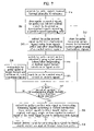
- FIG. 7 is a flowchart illustrating a beamforming procedure of an adaptive array antenna system according to an embodiment of the present invention.
- DPCCH dedicated physical control channel
- DPDCH dedicated physical data channel
- the DPCCH is composed of pilot symbols for estimating channel information, a transport format combination indicator (TFCI) field including spreading factor (SF) information of the backward channel, etc., a feedback information FBI) field that is a feedback signal for a transmit diversity and so on in the terminal, and a transmit power control (TPC) field including power control information.
- TFCI transport format combination indicator
- FBI feedback information
- TPC transmit power control
- the DPDCH is a channel that includes actual data of a user.
- FIG. 4 is a diagram illustrating a signal process of the DPDCH and the DPCCH used in the present invention, and more particularly a despreading process of the backward channels the DPCCH and the DPDCH.
- Cd and Cc denote channelization codes of the DPDCH and the DPCCH
- Sdpch denotes a scrambling code for the DPCH.
- the corresponding channelization codes Cd and Cc, and channel gains bd and bc are applied to the respective data to be transmitted.
- Inphase (I) and quadrature (Q) signals are then summed by summing all the data, and an S signal is produced by applying again the scrambling code Sdpch,n to a result of summing.
- the DPCCH is included only in the Q signal.
- s(t) The backward signal that is transmitted through the DPCH and received in the base transceiver system is called s(t), which is given by the following equation 1.
- s ( t ) [( b i d ( t )+ jb q d ( t )) C d ( t ) ⁇ d +jb q c ( t ) C c ( t ) ⁇ c ]s dpch ( t ) (1)
- b i d (t), b q d (t) represent I and Q data components of the DPDCH of a specified user
- b q c (t) represents the Q component of the DPCCH
- ⁇ d , ⁇ c represent channel gains of the DPDCH and the DPCCH, respectively.
- s dpch (t) represents a scrambling code of the whole DPCH.
- FIG. 5 is a diagram of a signal processing system according to first and second embodiments of the present invention.
- a signal processing apparatus including frequency down converters (not illustrated) for converting a received very high frequency signal into a baseband signal, analog-to-digital (A/D) converters (not illustrated) for converting an analog signal of the baseband into a digital signal, low-pass filters 301 - 1 to 301 -N for removing a noise of the received signal, fingers 322 - 1 to 322 -L for performing the spatial and temporal processes, a DPCH multipath searcher 320 , and a multipath controller 321 .
- the signal processing apparatus further includes buffers 312 a and 312 b , channel estimators 313 a and 313 b , combiners 315 , 316 , and 318 , an SIR estimator 317 , and a measurement report block 319 for performing their own corresponding functions using outputs of the multipath controller 321 and the fingers 322 - 1 to 322 -L, respectively.
- the fingers 322 - 1 to 322 -L include a beamformer 306 for performing the spatial process with respect to L (L is an integer not less than 2) paths, signal processing sections 302 , 303 - 1 to 303 -N, and 304 - 1 to 304 -N for the temporal process including despreading of the WCDMA system, and a weight vector calculation section 305 for beamforming.
- the low-pass filters 301 - 1 to 301 -N remove noise from signals received through an array of N antennas, respectively.
- the multipath searcher 320 separates the distributed multipath signals using the code characteristic according to the received time differences of the multipath signals, and then measures signal strengths of the respective paths.
- the multipath searcher also provides timing information of the separated multipath signals and a result of measurement of the signal strengths to the multipath controller 321 .
- the multipath controller 321 transfers the timing information of the signals of the respective paths and the code status to the fingers 322 - 1 to 322 -L, and allocates the paths to the respective fingers in the order of the signal strength of the respective paths, so that the respective fingers can continue the signal process in synchronization with the designated code. Also, the multipath controller 321 provides the timing information to a delay lock loop (DLL) 302 so that the delay lock loop 302 adjusts the timing of a reference antenna, and provides the timing information and the path allocation information to a beamforming module 306 and the measurement report block 319 .
- DLL delay lock loop
- the beamforming module 306 shares the timing information of the DPCH multipath searcher 320 and the information on which path among the multiple paths is received with the respective fingers 322 - 1 to 322 -L, so that it can recognize in advance the information on the beamforming execution time and so on.
- the low-pass-filtered signals are descrambled through descramblers 303 - 1 to 303 -N by a descrambling code of the DPCH according to the timing, and then despread through despreaders 304 - 1 to 304 -N by a despreading code of the DPCCH channel.
- the spreading factor (SF) of the DPDCH and the transport format combination indicator (TFCI) of the DPCCH can be recognized after completely receiving and decoding one frame of the DPCCH. Accordingly, the DPDCH should be stored in a memory such as a buffer until the TFCI information is obtained by despreading one frame of the DPCCH.
- the channelization code i.e., spreading code or despreading code
- the weight vector calculation section 305 calculates the weight vectors for the beamforming using the signals before and after despreading the DPCCH.
- the beamforming algorithm for calculating the weight vectors estimates autocorrelation matrices
- the maximum eigenvector corresponding to the maximum eigenvalue of a matrix expression composed of the two matrices is obtained, and then respective components of the eigenvector are estimated as the weight vectors to be applied to the DPCCH and the DPDCH, respectively.
- the different weight factors are obtained through the respective fingers 322 - 1 to 322 -L.
- the same beamforming algorithm is used for the respective fingers, but they are independently performed in the respective fingers since the input signals are different from one another.
- the modem structure for a smart antenna should be changed since the input signals for constructing the respective matrices are different from one another according to the system.
- the weight vector calculation section 305 obtains the weight vectors using the signal before despreading of the DPCCH signal and the signal after despreading of the DPCCH signal, the data of the DPDCH is continuously stored in the buffer until one frame of the DPCCH is completely despread.
- the weight vectors (i.e., updated values of weight vectors for one frame) estimated by the weight vector calculation section 305 are applied to the DPCCH channel by first weight value applying sections 307 - 1 to 307 -N.
- a DPCCH accumulator 308 accumulates the DPCCH to which the weight values are applied for a predetermined time.
- DPDCH despreaders 309 - 1 to 309 -N receive control information required for the despreading from the DPCCH accumulated for the predetermined time, and despread the DPDCH stored in the buffer.
- Second weight value applying sections 310 - 1 to 310 -N apply the estimated weight vectors to the DPDCH.
- a DPDCH accumulator 311 accumulates the DPDCH to which the weight values are applied for a predetermined time.
- the operation of the first weight value applying sections 307 - 1 to 307 -N and the second weight value applying sections 309 - 1 to 309 -N represents the process of performing the spatial process.
- the spatial process is performed after the weight vectors are completely obtained using the DPCCH signal for one frame, and the weight vector values should also be stored according as the update of the weight vectors is performed in the unit of a symbol, a slot, or another unit (for example, in the unit of a frame).
- the TFCI is decoded for the despreading of the DPDCH, and the DPDCH is actually despread using the decoded TFCI information. That is, the DPCCH signal is used for updating the weight vectors for the beamforming as it is continuously despread.
- the DPDCH beamforming is performed in the unit of a frame through a dot-product of the updated values of the weight vectors obtained for one frame and stored and the stored values of the DPDCH data to match the updated period of the weight vector.
- the DPCCH including the DPDCH despreading information is first received with a good quality through the beamforming, and then the DPDCH is beamformed and despread. This can provide better performance than the case that the weight vectors of the DPCCH and the DPDCH are separately obtained using the DPCCH and the DPDCH signals, respectively.
- the beamforming is simultaneously and separately performed in the respective fingers, considering that the weight vectors of the respective fingers are different from one another due to the different incident angles of the respective paths.
- channel estimators 313 a and 313 b detect the size and the phase of the signal offset through the respective paths of the fingers from the DPCCH and the DPDCH to which the weight values are applied.
- Distortion compensation applying sections 314 a to 314 c compensate for the signals of the DPCCH and the DPDCH to which the weight values are applied according to the detected size and phase.
- the signals of the respective fingers whose phases and sizes are compensated for are summed by combiners 316 and 318 and an SIR estimator 317 , and final values of TFCI, SIR, FBI, and TPC are outputted to the measurement report block 319 for the power control, SIR estimation, etc.
- the DPDCH signals of the respective fingers whose phases and sizes are compensated for are summed through another combiner 315 , and the final data is outputted.
- the weight vector calculation section 305 uses the beamforming algorithm, autocorrelation matrices of a signal vector v where only a desired signal component exists and a signal vector u where only an interference signal component exists are obtained by analyzing the desired signal component and the interference signal component of the DPCCH signal.
- the desired signal component Since the desired signal component has already been despread by the code of the desired signal in the despread DPCCH signal, the desired signal component can be obtained by processing the despread signal by the corresponding code and summing the processed signal in a gain period. Also, the component of the interference signal source can be obtained by subtracting the estimated value of the desired signal component from the signal before the despreading.
- the autocorrelation matrix of the desired signal source and the autocorrelation matrix of the interference signal can be obtained, and then the weight vectors for the smart antenna system can be obtained using the obtained matrices.
- R _ _ vv , ⁇ R _ _ uu correspond to
- R _ _ vv , ⁇ R _ _ uu is different, the system illustrated in FIG. 5 can be used as it is except for the portion of estimating the two matrices.
- the signal processing method for the basic spatial and temporal processes is the same as that illustrated in FIG. 5 .
- FIG. 6 shows signal processing system according to a third embodiment of the present invention.
- an autocorrelation matrix where only the desired signal component exists is obtained using only the despread DPCCH signal vector y .
- the weight vectors are calculated using a matrix expression as the following equation 4.
- the signal processing method for the basic spatial and temporal processes as shown in FIG. 6 does not use the signal before the despreading of the DPCCH, and is identical to the method illustrated in FIG. 5 except for the signal input into the weight vector calculation section 405 .
- the construction of FIG. 5 can be used as it is.
- FIG. 7 is a flowchart showing steps included in a beamforming process of the adaptive array antenna system according to the embodiments of the present invention.
- signals received through a plurality of antenna are separated into multiple paths by the DPCH multipath searcher 320 or 420 , and then allocated to the respective fingers (step S 10 ).
- the respective finger detects a signal for a specified user by descrambling the separated signal, and extracts a control signal by despreading the detected signal according to a predetermined (here, in order to extract the control signal with the spreading ratio of which is set to 256) spreading factor (step S 11 ).
- the respective finger also stores in the buffer the remaining signals except for the extracted control signal among the descrambled signals (step S 12 ). At this time, the buffer continuously stores the signals until the weight vectors for one frame period are obtained from the extracted control signal.
- a desired signal vector and an interference signal vector are extracted by despreading the extracted control signal (step S 13 ).
- the interference signal vector is extracted by subtracting the signal before the despreading of the control signal from the despread signal of the control channel (step S 13 ).
- the control channel has a fixed spreading factor (for example, 256) and a channelization code (or despreading code) predetermined between transmitting and receiving parts.
- the weight vectors are updated by paths, in the unit of a symbol, slot, or frame according to the first embodiment that uses the signal after the despreading of the control channel and the signal before the despreading of the control signal, the second embodiment that uses the desired signal and the interference signal, and the third embodiment that uses only the signal after the despreading of the control channel (step S 14 ).
- the updated weight vector is applied to the control channel(step S 15 ) in the corresponding unit.
- step S 17 It is judged if the period of the updated weight vector is the period of one frame (step S 17 ), and if not, the updated weight vector is accumulated by paths, and the stored remaining signals are continuously stored (step S 16 ). Then, it is judged if the period of the accumulated weight vector is the period of one frame (step S 17 ), and if not, the storage of the accumulated weight vector and the stored remaining signals is maintained (step S 16 ).
- the updated or accumulated weight vector is applied to a data channel (step S 18 ).
- a specified data signal is extracted by despreading by paths the remaining signals stored in the buffer using the control information (i.e., SF, channelization code, etc.) from the control channel to which the weight vector is applied for the period of one frame.
- the weight vector applied to the control signal of the same signal source is applied to the extracted data signal (step S 18 ).
- a desired signal is outputted through combination of the data signals to which the weight vectors are applied in the respective paths (step S 19 ).
- weight vectors obtained for each weight value updating period using the DPCCH without using the buffer may be sequentially applied to the remaining signals, and then the data channel may be extracted by sequentially despreading the signals to which the weight vectors are applied.
- the spatial and temporal processes are performed by adequately using the characteristic of the WCDMA system in a manner that not only the temporal process using the characteristic of the code but also the spatial process using the antenna array is performed, and thus the gain of the performance obtained from the antenna array as well as the gain of the performance of the existing WCDMA system can be obtained, thereby improving the communication quality.
Abstract
Description
s(t)=[(b i d(t)+jb q d(t))C d(t)βd +jb q c(t)C c(t)βc ]s dpch(t) (1)
of the respective signal vectors using a signal vector x before despreading of the DPCCH and a signal vector y after despreading of the DPCCH.
correspond to
of the
is different, the system illustrated in
Claims (12)
Applications Claiming Priority (2)
| Application Number | Priority Date | Filing Date | Title |
|---|---|---|---|
| KRP2001-31597 | 2001-06-07 | ||
| KR1020010031597A KR100803115B1 (en) | 2001-06-07 | 2001-06-07 | Method for processing signal in WCDMA with adaptive antenna array, System for the same |
Publications (2)
| Publication Number | Publication Date |
|---|---|
| US20020196767A1 US20020196767A1 (en) | 2002-12-26 |
| US7116702B2 true US7116702B2 (en) | 2006-10-03 |
Family
ID=36934159
Family Applications (1)
| Application Number | Title | Priority Date | Filing Date |
|---|---|---|---|
| US10/162,075 Expired - Fee Related US7116702B2 (en) | 2001-06-07 | 2002-06-05 | Signal processing method and apparatus in CDMA radio communication system |
Country Status (7)
| Country | Link |
|---|---|
| US (1) | US7116702B2 (en) |
| EP (1) | EP1265373B1 (en) |
| KR (1) | KR100803115B1 (en) |
| CN (1) | CN100483981C (en) |
| AT (1) | ATE336110T1 (en) |
| DE (1) | DE60213713T2 (en) |
| ES (1) | ES2269559T3 (en) |
Cited By (2)
| Publication number | Priority date | Publication date | Assignee | Title |
|---|---|---|---|---|
| US20050032476A1 (en) * | 2003-08-07 | 2005-02-10 | Samsung Electronics Co., Ltd. | Apparatus and method for receiving signals in a mobile communication system using adaptive antenna array technology |
| US20060176970A1 (en) * | 2002-12-27 | 2006-08-10 | Koninklijke Philips Electronics N.V. | Smart antenna solution for mobile handset |
Families Citing this family (19)
| Publication number | Priority date | Publication date | Assignee | Title |
|---|---|---|---|---|
| CN1625281A (en) * | 2003-12-01 | 2005-06-08 | 皇家飞利浦电子股份有限公司 | Communication system and device for mobile terminal with multiple antenna array |
| US8005128B1 (en) | 2003-09-23 | 2011-08-23 | Rambus Inc. | Methods for estimation and interference cancellation for signal processing |
| US8780957B2 (en) | 2005-01-14 | 2014-07-15 | Qualcomm Incorporated | Optimal weights for MMSE space-time equalizer of multicode CDMA system |
| RU2402885C2 (en) | 2005-03-10 | 2010-10-27 | Квэлкомм Инкорпорейтед | Classification of content for processing multimedia data |
| US20060269024A1 (en) * | 2005-05-27 | 2006-11-30 | Francis Dominique | Initial multi-path acquisition of random access channels |
| US7764656B2 (en) * | 2005-07-13 | 2010-07-27 | Alcatel-Lucent Usa Inc. | Methods of multipath acquisition for dedicated traffic channels |
| US7929499B2 (en) * | 2005-07-13 | 2011-04-19 | Alcatel-Lucent Usa Inc. | Methods of multipath acquisition for dedicated traffic channels |
| US7856071B2 (en) * | 2005-07-26 | 2010-12-21 | Alcatel-Lucent Usa Inc. | Multi-path acquisition in the presence of very high data rate users |
| US9113147B2 (en) | 2005-09-27 | 2015-08-18 | Qualcomm Incorporated | Scalability techniques based on content information |
| US8948260B2 (en) | 2005-10-17 | 2015-02-03 | Qualcomm Incorporated | Adaptive GOP structure in video streaming |
| US8654848B2 (en) | 2005-10-17 | 2014-02-18 | Qualcomm Incorporated | Method and apparatus for shot detection in video streaming |
| TWI345904B (en) * | 2005-11-21 | 2011-07-21 | Qualcomm Inc | Optimal weights for mmse space-time equalizer of multicode cdma system |
| WO2007070002A2 (en) | 2005-12-14 | 2007-06-21 | Telefonaktiebolaget Lm Ericsson (Publ) | Despreading-on-demand for use in spread spectrum receivers |
| CN101005302B (en) * | 2006-01-18 | 2013-02-13 | 上海原动力通信科技有限公司 | Down beam shaping method for limiting interference in time slot CDMA system |
| US9131164B2 (en) | 2006-04-04 | 2015-09-08 | Qualcomm Incorporated | Preprocessor method and apparatus |
| US20070297497A1 (en) * | 2006-06-21 | 2007-12-27 | Seibert Cristina A | Apparatus And Method For Interference Cancellation |
| US7697596B2 (en) * | 2006-09-21 | 2010-04-13 | Broadcom Corporation | Cluster path processor time alignment for signal suppression/separation in a wireless device |
| KR101247805B1 (en) * | 2008-11-03 | 2013-03-26 | 엘지전자 주식회사 | Method of transmitting data in multi-cell cooperative wireless communication system |
| US9930680B2 (en) * | 2014-09-05 | 2018-03-27 | Mitsubishi Electric Corporation | Interference identifying device, wireless communication apparatus, and interference identifying method |
Citations (9)
| Publication number | Priority date | Publication date | Assignee | Title |
|---|---|---|---|---|
| US6069912A (en) * | 1995-11-29 | 2000-05-30 | Ntt Mobile Communications Network, Inc. | Diversity receiver and its control method |
| WO2001013530A1 (en) | 1999-11-26 | 2001-02-22 | Nokia Networks Oy | Rake receiver |
| US6208632B1 (en) * | 1998-01-29 | 2001-03-27 | Sharp Laboratories Of America | System and method for CDMA channel estimation |
| US6415163B1 (en) * | 1995-05-24 | 2002-07-02 | Nokia Telecommunications Oy | Method for transmitting pilot channels and a cellular radio system |
| US6473467B1 (en) * | 2000-03-22 | 2002-10-29 | Qualcomm Incorporated | Method and apparatus for measuring reporting channel state information in a high efficiency, high performance communications system |
| US20030031234A1 (en) * | 2001-05-17 | 2003-02-13 | Smee John Edward | System and method for received signal prediction in wireless communications systems |
| US20030035468A1 (en) * | 2001-05-17 | 2003-02-20 | Corbaton Ivan Jesus Fernandez | System and method for adjusting combiner weights using an adaptive algorithm in wireless communications system |
| US6771219B2 (en) * | 2001-12-18 | 2004-08-03 | Lg Electronics Inc. | Adaptive beamforming method for smart antenna system |
| US6831943B1 (en) * | 1999-08-13 | 2004-12-14 | Texas Instruments Incorporated | Code division multiple access wireless system with closed loop mode using ninety degree phase rotation and beamformer verification |
Family Cites Families (3)
| Publication number | Priority date | Publication date | Assignee | Title |
|---|---|---|---|---|
| US5781845A (en) * | 1996-12-03 | 1998-07-14 | The Aerospace Corporation | Adaptive transmitting antenna |
| WO2001024396A1 (en) * | 1999-09-29 | 2001-04-05 | Nokia Mobile Phones Limited | Spread spectrum communication system |
| KR100584625B1 (en) * | 2001-05-17 | 2006-05-30 | 삼성전자주식회사 | Mobile communication apparatus and method including antenna array |
-
2001
- 2001-06-07 KR KR1020010031597A patent/KR100803115B1/en active IP Right Grant
-
2002
- 2002-06-05 US US10/162,075 patent/US7116702B2/en not_active Expired - Fee Related
- 2002-06-06 AT AT02012645T patent/ATE336110T1/en not_active IP Right Cessation
- 2002-06-06 DE DE60213713T patent/DE60213713T2/en not_active Expired - Lifetime
- 2002-06-06 ES ES02012645T patent/ES2269559T3/en not_active Expired - Lifetime
- 2002-06-06 EP EP02012645A patent/EP1265373B1/en not_active Expired - Lifetime
- 2002-06-07 CN CNB021227063A patent/CN100483981C/en not_active Expired - Fee Related
Patent Citations (9)
| Publication number | Priority date | Publication date | Assignee | Title |
|---|---|---|---|---|
| US6415163B1 (en) * | 1995-05-24 | 2002-07-02 | Nokia Telecommunications Oy | Method for transmitting pilot channels and a cellular radio system |
| US6069912A (en) * | 1995-11-29 | 2000-05-30 | Ntt Mobile Communications Network, Inc. | Diversity receiver and its control method |
| US6208632B1 (en) * | 1998-01-29 | 2001-03-27 | Sharp Laboratories Of America | System and method for CDMA channel estimation |
| US6831943B1 (en) * | 1999-08-13 | 2004-12-14 | Texas Instruments Incorporated | Code division multiple access wireless system with closed loop mode using ninety degree phase rotation and beamformer verification |
| WO2001013530A1 (en) | 1999-11-26 | 2001-02-22 | Nokia Networks Oy | Rake receiver |
| US6473467B1 (en) * | 2000-03-22 | 2002-10-29 | Qualcomm Incorporated | Method and apparatus for measuring reporting channel state information in a high efficiency, high performance communications system |
| US20030031234A1 (en) * | 2001-05-17 | 2003-02-13 | Smee John Edward | System and method for received signal prediction in wireless communications systems |
| US20030035468A1 (en) * | 2001-05-17 | 2003-02-20 | Corbaton Ivan Jesus Fernandez | System and method for adjusting combiner weights using an adaptive algorithm in wireless communications system |
| US6771219B2 (en) * | 2001-12-18 | 2004-08-03 | Lg Electronics Inc. | Adaptive beamforming method for smart antenna system |
Non-Patent Citations (3)
| Title |
|---|
| Etsi-Ran Universal Mobile Telecommunications System (UMTS); Multiplexing and Channel Coding (FDD). |
| Ikeda et al. "Experimental Evaluation of Coherent Rake Receiver for Broadband DS-CDMA Mobile Radio". |
| Smart antenna arrays for CDMA systems Thompson, J.S. et al; Personal Communications, IEEE [see also IEEE Wireless Communications] vol. 3, Issue 5, Oct. 1996 pp. 16-25. * |
Cited By (5)
| Publication number | Priority date | Publication date | Assignee | Title |
|---|---|---|---|---|
| US20060176970A1 (en) * | 2002-12-27 | 2006-08-10 | Koninklijke Philips Electronics N.V. | Smart antenna solution for mobile handset |
| US8102956B2 (en) * | 2002-12-27 | 2012-01-24 | St-Ericsson Sa | Smart antenna solution for mobile handset |
| US8467485B2 (en) | 2002-12-27 | 2013-06-18 | St-Ericsson Sa | Smart antenna solution for mobile handset |
| US20050032476A1 (en) * | 2003-08-07 | 2005-02-10 | Samsung Electronics Co., Ltd. | Apparatus and method for receiving signals in a mobile communication system using adaptive antenna array technology |
| US7236744B2 (en) * | 2003-08-07 | 2007-06-26 | Samsung Electronics Co., Ltd. | Apparatus and method for receiving signals in a mobile communication system using adaptive antenna array technology |
Also Published As
| Publication number | Publication date |
|---|---|
| ES2269559T3 (en) | 2007-04-01 |
| KR100803115B1 (en) | 2008-02-14 |
| EP1265373A2 (en) | 2002-12-11 |
| CN100483981C (en) | 2009-04-29 |
| EP1265373B1 (en) | 2006-08-09 |
| CN1391372A (en) | 2003-01-15 |
| DE60213713T2 (en) | 2007-08-09 |
| DE60213713D1 (en) | 2006-09-21 |
| US20020196767A1 (en) | 2002-12-26 |
| KR20020093185A (en) | 2002-12-16 |
| ATE336110T1 (en) | 2006-09-15 |
| EP1265373A3 (en) | 2003-04-23 |
Similar Documents
| Publication | Publication Date | Title |
|---|---|---|
| US7116702B2 (en) | Signal processing method and apparatus in CDMA radio communication system | |
| US7212578B2 (en) | Transmit diversity apparatus and method using two or more antennas | |
| KR101125529B1 (en) | A multi-antenna solution for mobile handset | |
| AU747307B2 (en) | Method and apparatus for multipath delay estimation in direct sequence spread spectrum communication systems | |
| EP1121767B1 (en) | A cdma receiver that shares a tracking device among multiple rake branches | |
| US20010017883A1 (en) | Rake receiver | |
| US8428106B2 (en) | Efficient method for forming and sharing impairment covariance matrix | |
| WO2001001594A1 (en) | Multistep rake combining method and apparatus | |
| JP2007515109A (en) | Frequency estimation method and apparatus for downlink of TD-SCDMA system | |
| US7142888B2 (en) | Radio communication method, base station and mobile station | |
| US20070189362A1 (en) | Method and system for channel estimation, related receiver and computer program product | |
| US8526556B2 (en) | Method and system for delay locked loop for rake receiver | |
| KR100355327B1 (en) | Communication terminal apparatus and radio communication method | |
| EP1124346A1 (en) | Method and apparatus for radio reception | |
| US7526012B2 (en) | Interference reduction apparatus and method | |
| KR100958596B1 (en) | Finger using Mixed Weighting, and Its Application for Demodulation Apparatus and Method | |
| KR100304670B1 (en) | Apparatus and method for estimating channel using pilot and traffic channel and DS/CDMA receiver comprising it | |
| KR100424537B1 (en) | Method for beamforming using smart antenna array | |
| KR100406529B1 (en) | Smart antenna base station system and the method of chip level beamforming based and his action method to use standard signal production apparatus and the method and he | |
| KR100581292B1 (en) | Hybrid chip-level beam forming apparatus and method thereof, and smart antenna base station using hybrid chip-level beam forming apparatus and driving method thereof | |
| JP2008512921A (en) | Wireless communication apparatus having multi-antenna and method thereof | |
| JP2000353984A (en) | Direct spread receiver | |
| KR100475384B1 (en) | Rake receiver and signal processing method of the same | |
| GB2370725A (en) | Optimal search method of DS-CDMA signal composed of time multiplexed known symbols and unknown symbols |
Legal Events
| Date | Code | Title | Description |
|---|---|---|---|
| AS | Assignment |
Owner name: LG ELECTRONICS INC., KOREA, REPUBLIC OF Free format text: ASSIGNMENT OF ASSIGNORS INTEREST;ASSIGNOR:SIM, DONG HI;REEL/FRAME:012976/0716 Effective date: 20020603 |
|
| FEPP | Fee payment procedure |
Free format text: PAYOR NUMBER ASSIGNED (ORIGINAL EVENT CODE: ASPN); ENTITY STATUS OF PATENT OWNER: LARGE ENTITY |
|
| FEPP | Fee payment procedure |
Free format text: PAYER NUMBER DE-ASSIGNED (ORIGINAL EVENT CODE: RMPN); ENTITY STATUS OF PATENT OWNER: LARGE ENTITY Free format text: PAYOR NUMBER ASSIGNED (ORIGINAL EVENT CODE: ASPN); ENTITY STATUS OF PATENT OWNER: LARGE ENTITY |
|
| FPAY | Fee payment |
Year of fee payment: 4 |
|
| FPAY | Fee payment |
Year of fee payment: 8 |
|
| FEPP | Fee payment procedure |
Free format text: MAINTENANCE FEE REMINDER MAILED (ORIGINAL EVENT CODE: REM.) |
|
| LAPS | Lapse for failure to pay maintenance fees |
Free format text: PATENT EXPIRED FOR FAILURE TO PAY MAINTENANCE FEES (ORIGINAL EVENT CODE: EXP.); ENTITY STATUS OF PATENT OWNER: LARGE ENTITY |
|
| STCH | Information on status: patent discontinuation |
Free format text: PATENT EXPIRED DUE TO NONPAYMENT OF MAINTENANCE FEES UNDER 37 CFR 1.362 |
|
| FP | Lapsed due to failure to pay maintenance fee |
Effective date: 20181003 |