US7114841B2 - Parallel/series LED strip - Google Patents
Parallel/series LED strip Download PDFInfo
- Publication number
- US7114841B2 US7114841B2 US10/805,931 US80593104A US7114841B2 US 7114841 B2 US7114841 B2 US 7114841B2 US 80593104 A US80593104 A US 80593104A US 7114841 B2 US7114841 B2 US 7114841B2
- Authority
- US
- United States
- Prior art keywords
- led
- conductor
- electrical
- leds
- light engine
- Prior art date
- Legal status (The legal status is an assumption and is not a legal conclusion. Google has not performed a legal analysis and makes no representation as to the accuracy of the status listed.)
- Active, expires
Links
- 239000004020 conductor Substances 0.000 claims abstract description 98
- 239000011810 insulating material Substances 0.000 claims abstract description 10
- 230000003750 conditioning effect Effects 0.000 claims description 12
- 238000004891 communication Methods 0.000 claims description 7
- 230000004888 barrier function Effects 0.000 claims description 5
- 238000009413 insulation Methods 0.000 claims description 5
- 239000000463 material Substances 0.000 claims description 5
- 239000003989 dielectric material Substances 0.000 claims description 3
- 230000005611 electricity Effects 0.000 claims description 3
- 239000012777 electrically insulating material Substances 0.000 claims description 2
- 238000000034 method Methods 0.000 description 7
- 230000004048 modification Effects 0.000 description 4
- 238000012986 modification Methods 0.000 description 4
- 230000004075 alteration Effects 0.000 description 2
- 238000005260 corrosion Methods 0.000 description 2
- 230000007797 corrosion Effects 0.000 description 2
- 230000001419 dependent effect Effects 0.000 description 2
- 239000002184 metal Substances 0.000 description 2
- 229910052751 metal Inorganic materials 0.000 description 2
- 238000005476 soldering Methods 0.000 description 2
- 241000252506 Characiformes Species 0.000 description 1
- 229920002943 EPDM rubber Polymers 0.000 description 1
- 239000004593 Epoxy Substances 0.000 description 1
- 239000011248 coating agent Substances 0.000 description 1
- 238000000576 coating method Methods 0.000 description 1
- 230000006835 compression Effects 0.000 description 1
- 238000007906 compression Methods 0.000 description 1
- 230000000694 effects Effects 0.000 description 1
- 229920001971 elastomer Polymers 0.000 description 1
- 239000008393 encapsulating agent Substances 0.000 description 1
- 239000003292 glue Substances 0.000 description 1
- 238000005286 illumination Methods 0.000 description 1
- 238000004519 manufacturing process Methods 0.000 description 1
- 150000002739 metals Chemical class 0.000 description 1
- 239000004033 plastic Substances 0.000 description 1
- 229920001296 polysiloxane Polymers 0.000 description 1
- 229920000915 polyvinyl chloride Polymers 0.000 description 1
- 230000001681 protective effect Effects 0.000 description 1
- 238000012163 sequencing technique Methods 0.000 description 1
- 210000002105 tongue Anatomy 0.000 description 1
Images


Classifications
-
- F—MECHANICAL ENGINEERING; LIGHTING; HEATING; WEAPONS; BLASTING
- F21—LIGHTING
- F21V—FUNCTIONAL FEATURES OR DETAILS OF LIGHTING DEVICES OR SYSTEMS THEREOF; STRUCTURAL COMBINATIONS OF LIGHTING DEVICES WITH OTHER ARTICLES, NOT OTHERWISE PROVIDED FOR
- F21V21/00—Supporting, suspending, or attaching arrangements for lighting devices; Hand grips
- F21V21/002—Supporting, suspending, or attaching arrangements for lighting devices; Hand grips making direct electrical contact, e.g. by piercing
-
- F—MECHANICAL ENGINEERING; LIGHTING; HEATING; WEAPONS; BLASTING
- F21—LIGHTING
- F21S—NON-PORTABLE LIGHTING DEVICES; SYSTEMS THEREOF; VEHICLE LIGHTING DEVICES SPECIALLY ADAPTED FOR VEHICLE EXTERIORS
- F21S4/00—Lighting devices or systems using a string or strip of light sources
- F21S4/10—Lighting devices or systems using a string or strip of light sources with light sources attached to loose electric cables, e.g. Christmas tree lights
-
- F—MECHANICAL ENGINEERING; LIGHTING; HEATING; WEAPONS; BLASTING
- F21—LIGHTING
- F21Y—INDEXING SCHEME ASSOCIATED WITH SUBCLASSES F21K, F21L, F21S and F21V, RELATING TO THE FORM OR THE KIND OF THE LIGHT SOURCES OR OF THE COLOUR OF THE LIGHT EMITTED
- F21Y2115/00—Light-generating elements of semiconductor light sources
- F21Y2115/10—Light-emitting diodes [LED]
-
- H—ELECTRICITY
- H01—ELECTRIC ELEMENTS
- H01R—ELECTRICALLY-CONDUCTIVE CONNECTIONS; STRUCTURAL ASSOCIATIONS OF A PLURALITY OF MUTUALLY-INSULATED ELECTRICAL CONNECTING ELEMENTS; COUPLING DEVICES; CURRENT COLLECTORS
- H01R9/00—Structural associations of a plurality of mutually-insulated electrical connecting elements, e.g. terminal strips or terminal blocks; Terminals or binding posts mounted upon a base or in a case; Bases therefor
- H01R9/03—Connectors arranged to contact a plurality of the conductors of a multiconductor cable, e.g. tapping connections
- H01R9/031—Connectors arranged to contact a plurality of the conductors of a multiconductor cable, e.g. tapping connections for multiphase cables, e.g. with contact members penetrating insulation of a plurality of conductors
Definitions
- LEDs Light emitting diodes
- LED-based light strings have been used in channel lettering systems, architectural border tube applications, under cabinet lighting applications and for general illumination.
- a known spoolable LED light string arranges the LEDs in parallel circuitry. This parallel arrangement requires a very low voltage output power supply (V out approximately 2.0 to 4.5 VDC) and a large amount of drive current capability. The large currents that must be delivered severely limits the distance that the power supply can be spaced from the LED strip as well as the length of the LED strip that can be driven by the power supply.
- LED string lights also use parallel/series combinations of LEDs. These known systems require that the LEDs mount to a printed circuit board as well as some sort of current limiting device. These known systems require the printed circuit board to be environmentally isolated, which is expensive. Furthermore, the printed circuit board based systems are also difficult to spool, to mount and to cut to length in addition to requiring the expense of the printed circuit board itself.
- LED light strings employ a plurality of LEDs wired in a series/parallel block that are run directly off AC power. These known systems require complicated designs to account for the alternating current.
- the present LED light engine contemplates an improved apparatus and method that overcomes the above-mentioned limitations and others.
- An LED light engine includes a flexible electrical cable and a plurality of LEDs.
- the flexible electrical cable includes first, second and third electrical conductors and an electrically insulating covering for the electrical conductors.
- the conductors are arranged substantially parallel with one another having an insulating material therebetween.
- a first LED including a first lead electrically connects to the first electrical conductor and a second lead of the first LED electrically connects to the second conductor.
- a second LED includes a first lead electrically connected to the second electrical conductor and a second lead electrically connected to the third electrical conductor.
- a third LED includes first and second leads electrically connected to the second conductor. The third LED is interposed between the first LED and the second LED.
- a method of manufacturing an LED light engine includes insulating first, second and third conductive elements to form an insulated conductor.
- the insulated conductor includes insulating material interposed between the conductive elements.
- the method further includes mechanically securing a plurality of LEDs spaced along the insulated conductor.
- the method further includes electrically contacting a first lead of a first LED of the plurality of LEDs to the first conductive element and a second lead of the first LED to the second conductive element.
- the method further includes electrically contacting a first lead and a second lead of a second LED of the plurality of LEDs to the second conductive element.
- the method further includes electrically separating the second conductive element between the first lead and the second lead of the second LED.
- the method further includes electrically contacting a first lead of a third LED of the plurality of LEDs to the second conductive element and a second lead of the third LED to the third conductive element.
- the second LED is interposed between the first LED and the third LED.
- a light string includes a plurality of LEDs connected to one another in parallel, a predetermined number of LEDs electrically connected to one another in series, and conditioning electronics in electrical communication with the plurality of LEDs.
- the predetermined number of LEDs is electrically interposed between adjacent LEDs that are electrically connected to one another in parallel.
- the conditioning electronics convert AC power to DC power for driving the LEDs.
- FIG. 1 is a perspective view of a portion of an LED light engine.
- FIG. 2 is an exploded perspective view of the LED light engine of FIG. 1 .
- FIG. 3 illustrates insulation-piercing members of the LED light engine of FIGS. 1 and 2 , and their interconnection with LED leads inside a socket housing (the socket housing is not shown in FIG. 3 ).
- FIG. 4 illustrates connecting of the insulation-piercing members with conductors of a flexible electrical cable.
- FIG. 5 is a perspective view of the LED light engine of FIG. 1 showing a plurality of LEDs attached to the flexible electrical cable, where the cable is shown in cross section.
- FIG. 6 is an elevation view of FIG. 5 .
- FIG. 7 is a view of the light engine of FIG. 1 mounted in a channel letter.
- FIG. 8 is a close-up view of the light engine of FIG. 1 mounted to a mounting surface such as the channel letter of FIG. 7 .
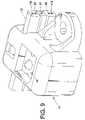
- FIG. 9 is a perspective view of a portion of an alternative LED light engine.
- a light engine 10 includes a flexible electrical conductor 12 having a socket housing 14 attached thereto.
- the socket housing 14 receives a light source, which in this embodiment is an LED 16 .
- the LED 16 is a pre-packaged LED of a type known to the art, e.g., an electroluminescent semi-conducting element arranged in a P4 (piranha) package with suitable epoxy or other encapsulant 18 .
- P4 piranha
- Other conventional light sources can be used with the light engine 10 including an incandescent light source.
- a plurality of socket housings 14 can attach to the insulated flexible electrical cord 12 at a plurality of locations along the cord, as seen in FIG. 5 , to form a light strip or light string.
- the light strip in a preferred embodiment, is powered by AC power.
- conditioning electronics 20 ( FIG. 5 ) communicate through the insulated flexible electrical cord 12 with the LEDs 16 .
- the conditioning electronics convert building power (e.g., 120 VAC in the United States or 220 VAC in Europe) to power suitable for driving the LEDs 16 of the light strip 10 .
- the conditioning electronics include a class II power supply having output power limited to 5 amperes and 30 volts. Class II power supplies are relatively safe due to the low voltages and currents produced and typically are not required by electrical codes to be arranged in safety conduits.
- the insulated flexible electric cord 12 includes a first conductor 22 , a second conductor 24 and a third conductor 26 .
- Each of the conductors 22 , 24 and 26 is preferably sized to be about 18 gauge. Additionally, each conductor is preferably stranded and includes a plurality of strands (e.g., seven strands).
- the first conductor 22 can be referred to as the positive (+) conductor
- the third conductor can be referred to as the negative ( ⁇ ) conductor
- the second conductor 24 can be referred to as the series conductor.
- Each of the conductors is situated generally parallel to one another and an insulating material 28 (e.g., rubber, PVC, silicone and/or EPDM), is situated between the conductors.
- an insulating material 28 e.g., rubber, PVC, silicone and/or EPDM
- the electrical cord 12 can include an alignment mechanism to facilitate alignment of the socket housing 14 on the electrical cord.
- the alignment mechanism is two grooves 30 , which have a V-shaped configuration, into which a portion of the socket housing 14 can be received. Alignment of the socket housing 14 with the grooves 30 aligns the internal components located in the socket housing, which will be described in more detail below, with the electrical conductors 22 , 24 and 26 in the cord 12 to promote a good electrical connection.
- the alignment mechanism can include a line drawn or made on the cord, or any conventional indicia to facilitate location of the socket housing 14 on the electrical cord.
- the socket housing 14 attaches to the insulated flexible electrical cord 12 .
- the socket housing is a molded body of a plastic or other suitable electrically insulating material.
- the socket housing 14 includes two sections: a hollow socket body 32 and a socket cover 34 .
- the socket body 32 is generally box-shaped and defines an LED seat 36 on an upper surface thereof.
- the LED seat 36 is dimensioned to receive a correspondingly sized LED 16 .
- the seat 36 includes a platform 38 upon which the LED 16 rests.
- the socket body 32 is hollow so that it can receive prongs 42 inside the socket body and below the LED platform 38 .
- the prongs 42 include insulation-piercing members that are arranged in a substantially fixed manner in slots or openings (not shown) in the socket body 32 .
- the prongs 42 are formed from sheet metal or another suitably electrically conductive material.
- each prong 42 is substantially planar and includes fingers 44 that extend towards the LED platform 38 to define slots 46 that receive corresponding LED leads 48 to effectuate electrical contact of the positive and negative terminals (anode and cathode) of the LED 16 with the corresponding positive or negative prong.
- the LED platform 38 includes openings 52 (only one is visible in FIG. 2 ) through which the terminals 48 protrude before entry into the slots 46 of the prongs 42 . Receiving of the LED leads 48 into the slots 46 does not include a soldering step.
- the LED 16 is optionally detachable from the prong 42 and the socket body 32 , for example to facilitate replacement of a failed LED.
- each prong 42 includes a bifurcated portion 56 that extends out of the socket body 32 toward the socket cover 34 such that when the socket body 32 is fastened to the socket cover 34 with the cable 12 sandwiched therebetween the bifurcated portion 56 of the prongs 42 punctures the cable insulation 28 and contacts a respective conductor 22 , 24 or 26 .
- Points 58 are formed at the end of the bifurcated portion to facilitate puncturing of the insulating material 28 .
- Each bifurcated portion 56 defines a gap 62 dimensioned to receive a respective conductor 22 , 24 or 26 .
- each conductor 22 , 24 or 26 compressively squeezes into the gap 62 of one of the prongs 42 when the socket body 32 is connected to the socket cover 34 .
- the compression preferably does not break or fracture the individual strands of the conductors, but does ensure a reliable electrical contact between the prongs 42 and a respective conductor 22 , 24 or 26 .
- the socket cover 34 is generally L-shaped and includes a base 70 that closes off the bottom of the socket body 32 and an upwardly extending wall 72 that covers the opposite side of the electrical cord 12 as the socket body 32 .
- the base 70 includes a first channel 74 located on one side of the base and a second channel 76 located on an opposite side of the base the channels 74 and 76 receive tongues (not visible in FIG. 2 ) that fit into the channels when the socket body 32 is fastened to the socket cover 34 .
- the upwardly extending wall 72 includes a knurl 82 positioned above the electrical cord 12 when the socket body 32 attaches to the socket cover 34 .
- the knurl 82 engages an opening 84 located on the socket body 32 .
- the knurl and opening provide a selective engagement between the socket body 32 and the socket cover 34 ; however, the socket body and the socket cover can secure to one another in any conventional manner.
- the wall 72 also includes alignment members 86 that are received in the grooves 30 of the electrical cord 12 . The alignment members 86 further align the socket housing 14 in a direction generally perpendicular to the length of the electrical cord 12 .
- an insulating member 88 is positioned between the prongs 42 to puncture the insulating material 28 and separate (e.g. cut) the series conductor 24 upon connection of the socket body 32 to the socket cover 34 .
- the insulating member 88 mounts inside the socket body 32 in a similar manner to the prongs 42 .
- the insulating member 88 includes a blade 90 to cut through the insulating material 28 and the series conductor 24 .
- the insulating member 88 is flat, similar to the prongs 42 , however, the insulating member 88 includes a dielectric material 92 positioned to prohibit the flow of electricity through the deflective material 92 when the socket housing 14 is affixed to the electrical cord 12 .
- the wall 72 can also include an insulation barrier (not shown) that is aligned to fit between the prongs 42 and separate the series conductor 24 between the prongs 42 when the socket body 32 attaches to the socket cover 34 .
- the insulation barrier can comprise a dielectric material that can puncture through the insulating material 28 of the electrical cord 12 and also cut through the series conductor 24 thus electrically separating the series conductor between two adjacent prongs 42 .
- the series conductor 24 can be cut by a feature integral to the socket body 32 and this feature can also electrically separate the series conductor 24 between two adjacent prongs 42 .
- a secondary component can be inserted into the socket housing 14 , i.e., through an opening (not shown) in the socket cover 34 .
- a mounting portion 94 also attaches to the socket housing 14 .
- the mounting portion in the light engine depicted in FIG. 2 includes an opening 96 that is adapted to receive a fastener.
- the mounting portion allows the socket housing 14 and thus the light engine 10 to attach to an associated surface such as a portion of outdoor signage, channel lettering systems, architectural border tube applications, under cabinet lighting applications and any surface to which one may want to mount a light engine.
- the light engine 10 can mount to the associated surface in other conventional manners including tape, hook and loop fasteners, as well as having a mounting portion that takes other configurations that the hook has shown.
- the mechanical connection between the socket housing 14 and the electrical cord 12 facilitates placement of the light engine 10 in a channel letter 100 .
- the LED 16 is generally perpendicular a plane that intersects the conductors 22 , 24 and 26 .
- Such a configuration allows for easy manipulation of the light string 10 on a mounting surface into a variety of configurations while emitting light away from the mounting surface.
- the light engine 10 mounts inside a channel letter 100 .
- a protective translucent cover (not shown) encloses the light engine 10 in the channel letter 100 .
- the light engine 10 mounts to the channel letter 100 by fasteners 102 received in the slots 94 of the mounting portion 92 and in openings 104 formed in the channel letter 100 .
- the light engine 10 can mount to the channel letter, or another mounting surface, in any conventional manner including clips, hook and loop fasteners, tape, glue and the like.
- the electrical connection between the components of the light engine 10 need not include auxiliary electrical components, such as resistors and the like, and need not include soldering.
- the conductors 22 , 24 and 26 , the prongs 42 and the LED leads 48 are formed from substantially similar metals to reduce galvanic corrosion at the electrically contacting interfaces, or are coated with a conductive coating that reduces galvanic corrosion at the interfaces.
- the orientation of the prongs 42 inside the socket body 32 is dependent upon the location of the socket housing 14 along the electrical cord 12 . As best shown in FIGS. 5 and 6 , the location of each bifurcated portion 56 of the prongs 42 is dependent upon the location of LED on the electrical cord 12 . As shown in FIG. 5 , the left-most LED 16 is electrically connected to the positive conductor 22 and the series conductor 24 . The right-most LED 16 is electrically connected to the negative conductor 26 and the series conductor 24 . The left-most LED and the right-most LED each have their prongs 42 offset from one another along the electrical cord 12 and the conductors 22 , 24 and 26 running within.
- the prongs 42 are also offset perpendicular to the length of the electrical cord 12 so that each prong contacts a different conductor.
- the central LEDs which are interposed between the left-most and right-most LEDs, have leads 48 that attach to prongs 42 to the second or series conductor 24 .
- the central LEDs have their prongs offset only along the length of the series conductor 24 .
- the insulating member 88 cuts through the series conductor 22 between each pair of prongs 42 for each LED 16 .
- a cord 12 ′ can include additional wires or conductors.
- the cord 12 ′ includes a positive conductor 22 ′, a series conductor 24 ′ and a negative conductor 26 ′.
- the cord 12 ′ also includes additional wires 110 and 112 . These wires can also communicate with an LED 16 ′ housed in a socket body 14 ′ which is attached to the cord. Information can be passed along the additional wires 110 and 112 . In such a case the wires 110 and 112 would also communicate with a control center.
- the additional wires can allow for dimming an LED in the string separately from other LEDs, perhaps due to a higher current draw.
- control examples that can be run through the additional wiring include sequencing LED's to create active effects, probing the LED socket for lifetime information, passing diagnostic information back and forth, reading temperature data from the socket (via electronics, thermocouples, or current and voltage characteristics), real time feedback to a power supply of voltage and current usage to allow for immediate modification of drive current or voltage, and addressing a resistive load at the module to allow for slight modifications to affect drive current.
- sequencing LED's to create active effects probing the LED socket for lifetime information, passing diagnostic information back and forth, reading temperature data from the socket (via electronics, thermocouples, or current and voltage characteristics), real time feedback to a power supply of voltage and current usage to allow for immediate modification of drive current or voltage, and addressing a resistive load at the module to allow for slight modifications to affect drive current.
- FIG. 6 it is contemplated that many more wires can be added to allow for the communication of information between the LEDs and the wires.
- a light engine 10 that has a parallel and series electrical configuration has been described.
- the conditioning electronics 20 allow DC power to run the LEDs 14 , allowing for a less complicated design. Furthermore, due to the electrical configuration, current limiting resistors are not required in the light engine. Also, by connecting some of the LEDs in series, the amount of current required to drive the light engine can be lessened.
- the light engine has been described with reference to the preferred embodiments. Obviously, modifications and alterations will occur to others upon reading and understanding the preceding detailed description. As just one example, the light engine was described with particular reference to LEDs; however, as indicated above, the light source can be any conventional light source, including incandescent bulbs. It is intended that the light engine be construed as including all such modifications and alterations insofar as they come within the scope of the appended claims or the equivalents thereof.
Abstract
Description
Claims (20)
Priority Applications (5)
| Application Number | Priority Date | Filing Date | Title |
|---|---|---|---|
| US10/805,931 US7114841B2 (en) | 2004-03-22 | 2004-03-22 | Parallel/series LED strip |
| PCT/US2005/007836 WO2005091973A2 (en) | 2004-03-22 | 2005-03-10 | Parallel/series led strip |
| EP05725168.8A EP1730437B1 (en) | 2004-03-22 | 2005-03-10 | Parallel/series led strip |
| AU2005226630A AU2005226630B2 (en) | 2004-03-22 | 2005-03-10 | Parallel/series LED strip |
| CN2005800135883A CN1950640B (en) | 2004-03-22 | 2005-03-10 | Parallel/series LED strip |
Applications Claiming Priority (1)
| Application Number | Priority Date | Filing Date | Title |
|---|---|---|---|
| US10/805,931 US7114841B2 (en) | 2004-03-22 | 2004-03-22 | Parallel/series LED strip |
Publications (2)
| Publication Number | Publication Date |
|---|---|
| US20050207151A1 US20050207151A1 (en) | 2005-09-22 |
| US7114841B2 true US7114841B2 (en) | 2006-10-03 |
Family
ID=34986058
Family Applications (1)
| Application Number | Title | Priority Date | Filing Date |
|---|---|---|---|
| US10/805,931 Active 2024-08-13 US7114841B2 (en) | 2004-03-22 | 2004-03-22 | Parallel/series LED strip |
Country Status (5)
| Country | Link |
|---|---|
| US (1) | US7114841B2 (en) |
| EP (1) | EP1730437B1 (en) |
| CN (1) | CN1950640B (en) |
| AU (1) | AU2005226630B2 (en) |
| WO (1) | WO2005091973A2 (en) |
Cited By (32)
| Publication number | Priority date | Publication date | Assignee | Title |
|---|---|---|---|---|
| US20060060881A1 (en) * | 2004-05-10 | 2006-03-23 | Daniel Anderlini | Fixture for holding and for connecting optoelectronic components such as PLCC2 and PLCC4 type light emitting diodes |
| US20060082315A1 (en) * | 2004-10-20 | 2006-04-20 | Timothy Chan | Method and system for attachment of light emmiting diodes to circuitry for use in lighting |
| US20060171159A1 (en) * | 2003-04-04 | 2006-08-03 | Daniel Anderlini | Rear light, particularly a stop light for a motor vehicle |
| US20060244622A1 (en) * | 2005-04-12 | 2006-11-02 | J & J Electronics, Inc. (A Corporation Of California) | Networkable controllers for LED lighting |
| US20070153526A1 (en) * | 2005-12-29 | 2007-07-05 | Lam Chiang Lim | LED housing |
| US20070153508A1 (en) * | 2005-12-30 | 2007-07-05 | Jeffrey Nall | Lighting strips with improved manufacturability |
| US20080200061A1 (en) * | 2007-02-15 | 2008-08-21 | Ipson Lee | Light-emitting cell module |
| US20080232105A1 (en) * | 2007-03-19 | 2008-09-25 | Lumination, Llc | Sealed lighting units |
| US20080232103A1 (en) * | 2007-03-19 | 2008-09-25 | Lumination, Llc | Flexible LED lighting strips |
| US20080277361A1 (en) * | 2007-05-07 | 2008-11-13 | The Coca-Cola Company | Dispenser with LED Lighting |
| US20090121654A1 (en) * | 2007-11-09 | 2009-05-14 | The Coca-Cola Company | LED Light Output Linearization |
| US20090161372A1 (en) * | 2007-12-21 | 2009-06-25 | Thomas Fay | Led socket string |
| US20090244884A1 (en) * | 2008-03-31 | 2009-10-01 | True Manufacturing Co. Inc. | Glass door merchandiser having led lights and mounting assembly therefor |
| US20100033964A1 (en) * | 2008-08-08 | 2010-02-11 | Photonics & Co., Limited | Light emitting diode (led) lighting device |
| US20100033068A1 (en) * | 2007-02-28 | 2010-02-11 | Compagnucci Holding S.P.A. | Built-in sliding rotating element for modular corner cabinets |
| US20100061025A1 (en) * | 2008-09-09 | 2010-03-11 | Parker Francis J | LED module for sign channel letters and driving circuit |
| US20100210133A1 (en) * | 2009-02-13 | 2010-08-19 | Yazaki Corporation | Illumination unit and wire harness equipped with the illumination unit |
| US20100327767A1 (en) * | 2009-06-26 | 2010-12-30 | Tpr Enterprises, Ltd. | System and method for led lampstring |
| US20110050120A1 (en) * | 2009-09-01 | 2011-03-03 | Hong Kong Applied Science And Technology Research Institute Co. Ltd. | Lighting control system and led lamp |
| US20110195597A1 (en) * | 2010-02-05 | 2011-08-11 | DAELIM ELECTRONICS Co., Ltd | Connection structure of hoistway cable and door interlock switch |
| US20120097988A1 (en) * | 2010-09-26 | 2012-04-26 | Jianwei Deng | LED Module |
| US20120129367A1 (en) * | 2010-11-23 | 2012-05-24 | Costa Jean-Paul | Network component comprising an electrical device |
| US20120268938A1 (en) * | 2011-04-20 | 2012-10-25 | Semisilicon Technology Corp. | Led light string |
| WO2013024046A1 (en) * | 2011-08-15 | 2013-02-21 | Osram Ag | Housing of electronic module, electronic module, light emitting module and backlight module |
| US20140340903A1 (en) * | 2013-05-20 | 2014-11-20 | Casey James Mahr | Temporary work light string with variably-positionable and re-positionable readily-replaced lamp, optionally with integral hangers, that are optionally electrically connected to plural electrical circuits |
| US9647349B1 (en) * | 2016-06-02 | 2017-05-09 | Elemental LED, Inc. | Through-insulation strip light connector |
| US10125964B2 (en) * | 2015-11-11 | 2018-11-13 | Itc Incorporated | Linear light connector |
| US10215911B2 (en) | 2013-04-17 | 2019-02-26 | Unity Opto Technology Co., Ltd. | Lighting assembly |
| US10317053B2 (en) * | 2016-08-19 | 2019-06-11 | B/E Aerospace, Inc. | Clamp for holding a flexible lighting unit |
| US10352544B2 (en) | 2013-04-17 | 2019-07-16 | Unity Opto Technology Co., Ltd. | Field-serviceable flat panel lighting device |
| US10364974B2 (en) | 2011-05-17 | 2019-07-30 | Unity Opto Technology Co., Ltd. | Flat panel lighting device and driving circuitry |
| US10386023B2 (en) | 2013-04-17 | 2019-08-20 | Unity Opto Technology Co., Ltd. | LED light fixture and assembly method therefor |
Families Citing this family (37)
| Publication number | Priority date | Publication date | Assignee | Title |
|---|---|---|---|---|
| US7210957B2 (en) * | 2004-04-06 | 2007-05-01 | Lumination Llc | Flexible high-power LED lighting system |
| US7160140B1 (en) * | 2005-07-13 | 2007-01-09 | Gelcore Llc | LED string light engine |
| US7520771B2 (en) | 2005-07-13 | 2009-04-21 | Lumination Llc | LED string light engine and devices that are illuminated by the string light engine |
| GB0517316D0 (en) * | 2005-08-24 | 2005-10-05 | Graham Morton | A lamp |
| WO2007023261A2 (en) * | 2005-08-24 | 2007-03-01 | Morton Graham | A lamp |
| US7341371B2 (en) * | 2005-10-21 | 2008-03-11 | Tyc Brother Industrial Co., Ltd. | LED light assembly with LED connecting device |
| US7156686B1 (en) | 2005-12-27 | 2007-01-02 | Gelcore Llc | Insulation displacement connection splice connector |
| US9564070B2 (en) * | 2006-10-05 | 2017-02-07 | GE Lighting Solutions, LLC | LED backlighting system for cabinet sign |
| CN108492726A (en) | 2006-10-05 | 2018-09-04 | 通用电气照明解决方案有限责任公司 | LED backlight system for cabinet sign |
| CN100543366C (en) * | 2006-11-14 | 2009-09-23 | 鹤山健豪灯饰企业有限公司 | Decorative chain |
| JP4259584B2 (en) * | 2007-02-28 | 2009-04-30 | 日亜化学工業株式会社 | Light emitting device cable and light emitting device using the same |
| KR100880665B1 (en) | 2007-06-28 | 2009-01-30 | 최성규 | Lighting device use LED |
| EP2023034A1 (en) | 2007-08-08 | 2009-02-11 | SHINING BLICK ENTERPRISES Co., Ltd. | Decorative light string. |
| DE102007057765A1 (en) | 2007-11-30 | 2009-06-04 | Osram Gesellschaft mit beschränkter Haftung | LED system, LED light and method of assembling a LED system |
| EP2334983A1 (en) * | 2008-10-06 | 2011-06-22 | Tridonic connection technology GmbH & Co KG | Lamp with led |
| WO2010049517A1 (en) * | 2008-10-31 | 2010-05-06 | Osram Gesellschaft mit beschränkter Haftung | A mounting arrangement for light sources and corresponding method |
| DE202009013278U1 (en) * | 2009-04-24 | 2010-09-16 | Ledon Lighting Jennersdorf Gmbh | Housed LED module with integrated electronics |
| US8540391B2 (en) * | 2010-06-18 | 2013-09-24 | Tyco Electronics Corporation | Light emitting diode interconnection system |
| IT1400807B1 (en) * | 2010-07-07 | 2013-07-02 | Tecnosystem S R L | ELECTRIC LIGHTING EQUIPMENT TO BE APPLIED TO FURNISHING AND SIMILAR ELEMENTS. |
| CN101915375B (en) * | 2010-07-30 | 2015-04-01 | 深圳市中庆微科技开发有限公司 | Flexible LED rope light |
| JP4963736B2 (en) * | 2010-10-28 | 2012-06-27 | 日本航空電子工業株式会社 | Lighting device |
| FR2973954B1 (en) * | 2011-04-06 | 2015-03-06 | David Zieder | CONNECTING BRACKET AND CORRESPONDING FLEXIBLE STRIP |
| WO2012158339A1 (en) * | 2011-05-13 | 2012-11-22 | 3M Innovative Properties Company | Flexible lighting assembly |
| EP2600470B1 (en) * | 2011-11-29 | 2017-01-04 | ABB Schweiz AG | Connecting device for a ribbon cable and electrical device with connected ribbon cable |
| CN103672532B (en) * | 2012-09-14 | 2018-05-01 | 欧司朗股份有限公司 | Lighting device and the lamps and lanterns including the lighting device |
| WO2014056539A1 (en) * | 2012-10-11 | 2014-04-17 | David Zieder | Connection support and corresponding flexible strip |
| TWM468615U (en) * | 2013-04-23 | 2013-12-21 | Chang-Fu Tsai | String structure of light emitting device (LED) |
| DE202014101257U1 (en) * | 2014-03-19 | 2015-07-01 | Zumtobel Lighting Gmbh | Lighting system |
| US10775034B1 (en) * | 2018-08-14 | 2020-09-15 | Hyperform, Inc. | Connectorized lighting system for surface appliques and method of retention of cylindrical objects |
| CN113016109B (en) * | 2019-02-01 | 2023-12-19 | 东莞舜威电业有限公司 | Luminous flat cable structure |
| CN110645494A (en) | 2019-09-06 | 2020-01-03 | 珠海博杰电子股份有限公司 | Electrodeless side-mounted LED lamp string, production method and production equipment thereof |
| CN110726081B (en) | 2019-09-06 | 2024-02-27 | 珠海博杰电子股份有限公司 | LED lamp string, production method and production equipment thereof |
| CN110736034A (en) | 2019-09-06 | 2020-01-31 | 珠海博杰电子股份有限公司 | LED hose lamp, production method and production equipment thereof |
| US11603983B2 (en) | 2019-09-06 | 2023-03-14 | Zhuhai Bojay Electronics Co. Ltd. | LED light string ornament and method for manufacturing the same |
| CN110630923A (en) | 2019-09-06 | 2019-12-31 | 珠海博杰电子股份有限公司 | Electrodeless flat-pasted LED lamp string, production method and production equipment thereof |
| CN112838153A (en) * | 2021-02-02 | 2021-05-25 | 东莞市华彩威科技有限公司 | LED lamp string, manufacturing method and LED device used in LED lamp string |
| CN115405878A (en) | 2021-05-26 | 2022-11-29 | 珠海博杰电子股份有限公司 | LED lamp string with single wire and lighting device |
Citations (46)
| Publication number | Priority date | Publication date | Assignee | Title |
|---|---|---|---|---|
| US671338A (en) | 1900-09-10 | 1901-04-02 | Electric Lighting Boards Ltd | Conductor and contact for electrical glow-lamps. |
| US3115541A (en) | 1962-05-21 | 1963-12-24 | Pullman Inc | Electrical wiring connector |
| US4173035A (en) | 1977-12-01 | 1979-10-30 | Media Masters, Inc. | Tape strip for effecting moving light display |
| US4419538A (en) | 1981-11-13 | 1983-12-06 | W. L. Gore & Associates, Inc. | Under-carpet coaxial cable |
| US4631650A (en) | 1984-10-24 | 1986-12-23 | Ahroni Joseph M | Series-parallel connected miniature light set |
| US4638117A (en) | 1985-06-14 | 1987-01-20 | Lynenwerk Gmbh & Co. Kommanditgesellschaft | Electrical cable for communication purposes |
| US4777573A (en) | 1988-06-24 | 1988-10-11 | Liao Nan Whair | Miniature light set |
| US4779177A (en) | 1984-10-24 | 1988-10-18 | Ahroni Joseph M | Series-parallel connected miniature light set |
| US4807098A (en) | 1984-10-24 | 1989-02-21 | Ahroni Joseph M | Lampholders for miniature light sets |
| US4813883A (en) | 1987-03-23 | 1989-03-21 | Staley Donald K | Impact fastening electrical wire connector |
| US4815814A (en) | 1986-09-02 | 1989-03-28 | Cooper Industries, Inc. | Under-carpet flat cable assembly and method of forming a turn in same |
| US4855882A (en) | 1988-03-29 | 1989-08-08 | Lightgraphix Limited | Lighting apparatus |
| US4899266A (en) | 1984-10-24 | 1990-02-06 | Ahroni Joseph M | Miniature light sets and lampholders and method for making them |
| US4984999A (en) | 1990-05-17 | 1991-01-15 | Leake Sam S | String of lights specification |
| US5010463A (en) | 1990-04-30 | 1991-04-23 | Ross David L | Electrified bulletin board with illuminable push-pin |
| US5051877A (en) | 1990-11-05 | 1991-09-24 | Liao Nan W | Miniature light set |
| US5109324A (en) | 1984-10-24 | 1992-04-28 | Ahroni Joseph M | Light unit for decorative miniature light sets |
| US5121310A (en) | 1984-10-24 | 1992-06-09 | Ahroni Joseph M | Chaser decorative light set |
| US5141449A (en) | 1991-09-06 | 1992-08-25 | Vista Manufacturing, Inc. | Snap-on light socket |
| US5154508A (en) | 1990-01-05 | 1992-10-13 | Ahroni Joseph M | Locking system for light assembly with push-in bulb unit |
| US5238424A (en) | 1991-12-05 | 1993-08-24 | Vindum Jorgen O | In-line extension cord |
| US5330368A (en) | 1992-02-07 | 1994-07-19 | Masaaki Tsuruzono | Apparatus for lighting baseless bulbs |
| US5337225A (en) | 1993-01-06 | 1994-08-09 | The Standard Products Company | Lighting strip system |
| US5367122A (en) | 1991-06-07 | 1994-11-22 | Olano Luis A R De | Ornamental electrical molding |
| US5526250A (en) | 1994-11-23 | 1996-06-11 | Ting; Cheng Y. | Structure of lamp socket |
| US5559681A (en) | 1994-05-13 | 1996-09-24 | Cnc Automation, Inc. | Flexible, self-adhesive, modular lighting system |
| US5584567A (en) | 1995-06-07 | 1996-12-17 | Rumpel; Donald | Decorative light mount |
| US5601448A (en) | 1995-03-21 | 1997-02-11 | Sunskill Industries, Ltd. | Connector for lighting system and method |
| US5829865A (en) | 1996-07-03 | 1998-11-03 | Ahroni; Joseph M. | Miniature push-in type light unit |
| US5934930A (en) | 1996-07-02 | 1999-08-10 | Pouyet S.A. | Interconnection of two electric cables |
| US5967823A (en) | 1996-09-03 | 1999-10-19 | Tsui; Pui-Hing | Structure for a belt light and an extension device therefor |
| US6017241A (en) | 1998-01-26 | 2000-01-25 | Tivoli Industries, Inc. | Aisle lighting lampholder |
| US6079848A (en) | 1996-07-03 | 2000-06-27 | Ahroni; Joseph M. | Lamp unit with improved push-in type bulb holder |
| US6095847A (en) | 1999-06-01 | 2000-08-01 | Lin; Yuan | Watertight lamp socket for lamp belt |
| US6116944A (en) | 1999-07-12 | 2000-09-12 | Tseng; Jeou-Nan | Ornamental bulb socket |
| US6261119B1 (en) | 1999-01-22 | 2001-07-17 | Framatome Connectors International | Led light strip insulation-piercing connector |
| US6290365B1 (en) | 1998-09-04 | 2001-09-18 | Robert A. Schlesinger | Lighting device adapted to be removably positioned at any point along an electrical cord |
| US6367952B1 (en) | 1998-05-08 | 2002-04-09 | Ventur Research & Development Inc | Programmable string of lights |
| US6383013B1 (en) | 1998-09-15 | 2002-05-07 | Mannesmann Vdo Ag | Display instrument with a cable clamping clip |
| US6478450B1 (en) | 2001-04-30 | 2002-11-12 | Zdenko Grajcar | Lighting system |
| WO2002097770A2 (en) | 2001-05-25 | 2002-12-05 | Gelcore, Llc | Illuminated signage employing light emitting diodes |
| US20030063463A1 (en) * | 2001-10-01 | 2003-04-03 | Sloanled, Inc. | Channel letter lighting using light emitting diodes |
| US6558021B2 (en) * | 2001-08-10 | 2003-05-06 | Leotek Electronics Corporation | Light emitting diode modules for illuminated signs |
| US6578986B2 (en) | 2001-06-29 | 2003-06-17 | Permlight Products, Inc. | Modular mounting arrangement and method for light emitting diodes |
| US20040075399A1 (en) | 2002-10-22 | 2004-04-22 | Hall David Charles | LED light engine for AC operation and methods of fabricating same |
| US6942360B2 (en) | 2003-10-01 | 2005-09-13 | Enertron, Inc. | Methods and apparatus for an LED light engine |
Family Cites Families (3)
| Publication number | Priority date | Publication date | Assignee | Title |
|---|---|---|---|---|
| US5672000A (en) * | 1994-09-14 | 1997-09-30 | Lin; Tayeh | Decorative lamp strip |
| US6631957B2 (en) * | 2000-07-24 | 2003-10-14 | Po Shun Leong | Dismantleable chair |
| US6942630B2 (en) * | 2002-04-16 | 2005-09-13 | Biodex Medical Systems, Inc. | Inflatable suspension harness/body jacket |
-
2004
- 2004-03-22 US US10/805,931 patent/US7114841B2/en active Active
-
2005
- 2005-03-10 WO PCT/US2005/007836 patent/WO2005091973A2/en active Application Filing
- 2005-03-10 AU AU2005226630A patent/AU2005226630B2/en not_active Ceased
- 2005-03-10 EP EP05725168.8A patent/EP1730437B1/en not_active Not-in-force
- 2005-03-10 CN CN2005800135883A patent/CN1950640B/en not_active Expired - Fee Related
Patent Citations (47)
| Publication number | Priority date | Publication date | Assignee | Title |
|---|---|---|---|---|
| US671338A (en) | 1900-09-10 | 1901-04-02 | Electric Lighting Boards Ltd | Conductor and contact for electrical glow-lamps. |
| US3115541A (en) | 1962-05-21 | 1963-12-24 | Pullman Inc | Electrical wiring connector |
| US4173035A (en) | 1977-12-01 | 1979-10-30 | Media Masters, Inc. | Tape strip for effecting moving light display |
| US4419538A (en) | 1981-11-13 | 1983-12-06 | W. L. Gore & Associates, Inc. | Under-carpet coaxial cable |
| US4899266A (en) | 1984-10-24 | 1990-02-06 | Ahroni Joseph M | Miniature light sets and lampholders and method for making them |
| US4631650A (en) | 1984-10-24 | 1986-12-23 | Ahroni Joseph M | Series-parallel connected miniature light set |
| US4779177A (en) | 1984-10-24 | 1988-10-18 | Ahroni Joseph M | Series-parallel connected miniature light set |
| US4807098A (en) | 1984-10-24 | 1989-02-21 | Ahroni Joseph M | Lampholders for miniature light sets |
| US5121310A (en) | 1984-10-24 | 1992-06-09 | Ahroni Joseph M | Chaser decorative light set |
| US5109324A (en) | 1984-10-24 | 1992-04-28 | Ahroni Joseph M | Light unit for decorative miniature light sets |
| US4638117A (en) | 1985-06-14 | 1987-01-20 | Lynenwerk Gmbh & Co. Kommanditgesellschaft | Electrical cable for communication purposes |
| US4815814A (en) | 1986-09-02 | 1989-03-28 | Cooper Industries, Inc. | Under-carpet flat cable assembly and method of forming a turn in same |
| US4813883A (en) | 1987-03-23 | 1989-03-21 | Staley Donald K | Impact fastening electrical wire connector |
| US4855882A (en) | 1988-03-29 | 1989-08-08 | Lightgraphix Limited | Lighting apparatus |
| US4777573A (en) | 1988-06-24 | 1988-10-11 | Liao Nan Whair | Miniature light set |
| US5154508A (en) | 1990-01-05 | 1992-10-13 | Ahroni Joseph M | Locking system for light assembly with push-in bulb unit |
| US5010463A (en) | 1990-04-30 | 1991-04-23 | Ross David L | Electrified bulletin board with illuminable push-pin |
| US4984999A (en) | 1990-05-17 | 1991-01-15 | Leake Sam S | String of lights specification |
| US5051877A (en) | 1990-11-05 | 1991-09-24 | Liao Nan W | Miniature light set |
| US5367122A (en) | 1991-06-07 | 1994-11-22 | Olano Luis A R De | Ornamental electrical molding |
| US5141449A (en) | 1991-09-06 | 1992-08-25 | Vista Manufacturing, Inc. | Snap-on light socket |
| US5238424A (en) | 1991-12-05 | 1993-08-24 | Vindum Jorgen O | In-line extension cord |
| US5330368A (en) | 1992-02-07 | 1994-07-19 | Masaaki Tsuruzono | Apparatus for lighting baseless bulbs |
| US5337225A (en) | 1993-01-06 | 1994-08-09 | The Standard Products Company | Lighting strip system |
| US5559681A (en) | 1994-05-13 | 1996-09-24 | Cnc Automation, Inc. | Flexible, self-adhesive, modular lighting system |
| US5526250A (en) | 1994-11-23 | 1996-06-11 | Ting; Cheng Y. | Structure of lamp socket |
| US5601448A (en) | 1995-03-21 | 1997-02-11 | Sunskill Industries, Ltd. | Connector for lighting system and method |
| US5584567A (en) | 1995-06-07 | 1996-12-17 | Rumpel; Donald | Decorative light mount |
| US5934930A (en) | 1996-07-02 | 1999-08-10 | Pouyet S.A. | Interconnection of two electric cables |
| US6079848A (en) | 1996-07-03 | 2000-06-27 | Ahroni; Joseph M. | Lamp unit with improved push-in type bulb holder |
| US5829865A (en) | 1996-07-03 | 1998-11-03 | Ahroni; Joseph M. | Miniature push-in type light unit |
| US5967823A (en) | 1996-09-03 | 1999-10-19 | Tsui; Pui-Hing | Structure for a belt light and an extension device therefor |
| US6017241A (en) | 1998-01-26 | 2000-01-25 | Tivoli Industries, Inc. | Aisle lighting lampholder |
| US6367952B1 (en) | 1998-05-08 | 2002-04-09 | Ventur Research & Development Inc | Programmable string of lights |
| US6290365B1 (en) | 1998-09-04 | 2001-09-18 | Robert A. Schlesinger | Lighting device adapted to be removably positioned at any point along an electrical cord |
| US6383013B1 (en) | 1998-09-15 | 2002-05-07 | Mannesmann Vdo Ag | Display instrument with a cable clamping clip |
| US6261119B1 (en) | 1999-01-22 | 2001-07-17 | Framatome Connectors International | Led light strip insulation-piercing connector |
| US6095847A (en) | 1999-06-01 | 2000-08-01 | Lin; Yuan | Watertight lamp socket for lamp belt |
| US6116944A (en) | 1999-07-12 | 2000-09-12 | Tseng; Jeou-Nan | Ornamental bulb socket |
| US6478450B1 (en) | 2001-04-30 | 2002-11-12 | Zdenko Grajcar | Lighting system |
| WO2002097770A2 (en) | 2001-05-25 | 2002-12-05 | Gelcore, Llc | Illuminated signage employing light emitting diodes |
| US6660935B2 (en) * | 2001-05-25 | 2003-12-09 | Gelcore Llc | LED extrusion light engine and connector therefor |
| US6578986B2 (en) | 2001-06-29 | 2003-06-17 | Permlight Products, Inc. | Modular mounting arrangement and method for light emitting diodes |
| US6558021B2 (en) * | 2001-08-10 | 2003-05-06 | Leotek Electronics Corporation | Light emitting diode modules for illuminated signs |
| US20030063463A1 (en) * | 2001-10-01 | 2003-04-03 | Sloanled, Inc. | Channel letter lighting using light emitting diodes |
| US20040075399A1 (en) | 2002-10-22 | 2004-04-22 | Hall David Charles | LED light engine for AC operation and methods of fabricating same |
| US6942360B2 (en) | 2003-10-01 | 2005-09-13 | Enertron, Inc. | Methods and apparatus for an LED light engine |
Non-Patent Citations (3)
| Title |
|---|
| International Search Report from PCT/US05/07836. |
| U.S. Appl. No. 10/819,328. |
| U.S. Appl. No. 10/820,838. |
Cited By (56)
| Publication number | Priority date | Publication date | Assignee | Title |
|---|---|---|---|---|
| US20060171159A1 (en) * | 2003-04-04 | 2006-08-03 | Daniel Anderlini | Rear light, particularly a stop light for a motor vehicle |
| US20060060881A1 (en) * | 2004-05-10 | 2006-03-23 | Daniel Anderlini | Fixture for holding and for connecting optoelectronic components such as PLCC2 and PLCC4 type light emitting diodes |
| US7435143B2 (en) * | 2004-05-10 | 2008-10-14 | Cml Innovative Technologies | Fixture for optoelectronic components such as PLCC2-type and PLCC4-type light emitting diodes |
| US20060082315A1 (en) * | 2004-10-20 | 2006-04-20 | Timothy Chan | Method and system for attachment of light emmiting diodes to circuitry for use in lighting |
| US20060244622A1 (en) * | 2005-04-12 | 2006-11-02 | J & J Electronics, Inc. (A Corporation Of California) | Networkable controllers for LED lighting |
| US7821212B2 (en) | 2005-04-12 | 2010-10-26 | J & J Electronics, Inc. | Networkable controllers for LED lighting |
| US20080309504A1 (en) * | 2005-12-29 | 2008-12-18 | Lam Chiang Lim | LED housing |
| US20070153526A1 (en) * | 2005-12-29 | 2007-07-05 | Lam Chiang Lim | LED housing |
| US7549773B2 (en) | 2005-12-29 | 2009-06-23 | Lam Chiang Lim | LED housing |
| US20070153508A1 (en) * | 2005-12-30 | 2007-07-05 | Jeffrey Nall | Lighting strips with improved manufacturability |
| US8398261B2 (en) * | 2005-12-30 | 2013-03-19 | Ge Lighting Solutions Llc | Lighting strips with improved manufacturability |
| US20080200061A1 (en) * | 2007-02-15 | 2008-08-21 | Ipson Lee | Light-emitting cell module |
| US7442070B2 (en) * | 2007-02-15 | 2008-10-28 | Super Link Electronics Co., Ltd. | Light-emitting cell module |
| US20100033068A1 (en) * | 2007-02-28 | 2010-02-11 | Compagnucci Holding S.P.A. | Built-in sliding rotating element for modular corner cabinets |
| WO2008115983A1 (en) | 2007-03-19 | 2008-09-25 | Lumination Llc | Sealed lighting units |
| US20080232103A1 (en) * | 2007-03-19 | 2008-09-25 | Lumination, Llc | Flexible LED lighting strips |
| US7931386B2 (en) | 2007-03-19 | 2011-04-26 | GE Lighting Solutions, LLC | Flexible LED lighting strips including overmolding encasement and attached parallel electrical conductors |
| US20080232105A1 (en) * | 2007-03-19 | 2008-09-25 | Lumination, Llc | Sealed lighting units |
| US7687288B2 (en) | 2007-03-19 | 2010-03-30 | Lumination Llc | Sealed lighting units |
| US20080277361A1 (en) * | 2007-05-07 | 2008-11-13 | The Coca-Cola Company | Dispenser with LED Lighting |
| US20090121654A1 (en) * | 2007-11-09 | 2009-05-14 | The Coca-Cola Company | LED Light Output Linearization |
| US8013541B2 (en) | 2007-11-09 | 2011-09-06 | The Coca-Cola Company | LED light output linearization |
| US7586274B2 (en) | 2007-11-09 | 2009-09-08 | The Coca-Cola Company | LED light output linearization |
| US20090289576A1 (en) * | 2007-11-09 | 2009-11-26 | The Coca-Cola Company | Led light output linearization |
| US20090161372A1 (en) * | 2007-12-21 | 2009-06-25 | Thomas Fay | Led socket string |
| US7731396B2 (en) * | 2007-12-21 | 2010-06-08 | Tpr Enterprises, Ltd. | LED socket string |
| US20090244884A1 (en) * | 2008-03-31 | 2009-10-01 | True Manufacturing Co. Inc. | Glass door merchandiser having led lights and mounting assembly therefor |
| US20100033964A1 (en) * | 2008-08-08 | 2010-02-11 | Photonics & Co., Limited | Light emitting diode (led) lighting device |
| US20100061025A1 (en) * | 2008-09-09 | 2010-03-11 | Parker Francis J | LED module for sign channel letters and driving circuit |
| US8611057B2 (en) | 2008-09-09 | 2013-12-17 | Inshore Holdings, Llc | LED module for sign channel letters and driving circuit |
| US20110085271A1 (en) * | 2008-09-09 | 2011-04-14 | Inshore Holdings, Llc | LED Modules for Sign Channel Letters and Driving Circuit |
| US8305717B2 (en) | 2008-09-09 | 2012-11-06 | Inshore Holdings, Llc | LED modules for sign channel letters and driving circuit |
| US20100210133A1 (en) * | 2009-02-13 | 2010-08-19 | Yazaki Corporation | Illumination unit and wire harness equipped with the illumination unit |
| US8128427B2 (en) * | 2009-02-13 | 2012-03-06 | Yazaki Corporation | Illumination unit and wire harness equipped with the illumination unit |
| US20100327767A1 (en) * | 2009-06-26 | 2010-12-30 | Tpr Enterprises, Ltd. | System and method for led lampstring |
| US8373360B2 (en) * | 2009-09-01 | 2013-02-12 | Hong Kong Applied Science And Technology Research Institute Co. Ltd. | Lighting control system and LED lamp |
| US20110050120A1 (en) * | 2009-09-01 | 2011-03-03 | Hong Kong Applied Science And Technology Research Institute Co. Ltd. | Lighting control system and led lamp |
| US20110195597A1 (en) * | 2010-02-05 | 2011-08-11 | DAELIM ELECTRONICS Co., Ltd | Connection structure of hoistway cable and door interlock switch |
| US8454199B2 (en) * | 2010-09-26 | 2013-06-04 | Jianwei Deng | LED module |
| US20120097988A1 (en) * | 2010-09-26 | 2012-04-26 | Jianwei Deng | LED Module |
| US8613625B2 (en) * | 2010-11-23 | 2013-12-24 | Saia-Burgess Controls Ag | Network component comprising an electrical device |
| US20120129367A1 (en) * | 2010-11-23 | 2012-05-24 | Costa Jean-Paul | Network component comprising an electrical device |
| US20120268938A1 (en) * | 2011-04-20 | 2012-10-25 | Semisilicon Technology Corp. | Led light string |
| US8651700B2 (en) * | 2011-04-20 | 2014-02-18 | Semisilicon Technology Corp. | LED light string |
| US10422518B2 (en) | 2011-05-17 | 2019-09-24 | Unity Opto Technology Co., Ltd. | Flat panel lighting device |
| US10364974B2 (en) | 2011-05-17 | 2019-07-30 | Unity Opto Technology Co., Ltd. | Flat panel lighting device and driving circuitry |
| WO2013024046A1 (en) * | 2011-08-15 | 2013-02-21 | Osram Ag | Housing of electronic module, electronic module, light emitting module and backlight module |
| US9982869B2 (en) | 2011-08-15 | 2018-05-29 | Osram Gmbh | Housing of electronic module, electronic module, light emitting module and backlight module |
| US10215911B2 (en) | 2013-04-17 | 2019-02-26 | Unity Opto Technology Co., Ltd. | Lighting assembly |
| US10352544B2 (en) | 2013-04-17 | 2019-07-16 | Unity Opto Technology Co., Ltd. | Field-serviceable flat panel lighting device |
| US10386023B2 (en) | 2013-04-17 | 2019-08-20 | Unity Opto Technology Co., Ltd. | LED light fixture and assembly method therefor |
| US9557019B2 (en) * | 2013-05-20 | 2017-01-31 | Casey James Mahr | Temporary work light string with variably-positionable and re-positionable readily-replaced lamp, optionally with integral hangers, that are optionally electrically connected to plural electrical circuits |
| US20140340903A1 (en) * | 2013-05-20 | 2014-11-20 | Casey James Mahr | Temporary work light string with variably-positionable and re-positionable readily-replaced lamp, optionally with integral hangers, that are optionally electrically connected to plural electrical circuits |
| US10125964B2 (en) * | 2015-11-11 | 2018-11-13 | Itc Incorporated | Linear light connector |
| US9647349B1 (en) * | 2016-06-02 | 2017-05-09 | Elemental LED, Inc. | Through-insulation strip light connector |
| US10317053B2 (en) * | 2016-08-19 | 2019-06-11 | B/E Aerospace, Inc. | Clamp for holding a flexible lighting unit |
Also Published As
| Publication number | Publication date |
|---|---|
| AU2005226630B2 (en) | 2010-12-16 |
| EP1730437A2 (en) | 2006-12-13 |
| CN1950640B (en) | 2012-12-12 |
| US20050207151A1 (en) | 2005-09-22 |
| EP1730437A4 (en) | 2007-05-16 |
| WO2005091973A2 (en) | 2005-10-06 |
| EP1730437B1 (en) | 2014-06-18 |
| WO2005091973A3 (en) | 2006-03-30 |
| CN1950640A (en) | 2007-04-18 |
| AU2005226630A1 (en) | 2005-10-06 |
Similar Documents
| Publication | Publication Date | Title |
|---|---|---|
| US7114841B2 (en) | Parallel/series LED strip | |
| US7217012B2 (en) | Illuminated signage employing light emitting diodes | |
| EP1965123B1 (en) | Lighting apparatus cable and lighting apparatus using the same | |
| AU2005234407B2 (en) | Flexible high-power LED lighting system | |
| US7377669B2 (en) | LED module and system of LED modules with integral branch connectors | |
| US7241031B2 (en) | Channel letter lighting system using high output white light emitting diodes | |
| JP2007335345A (en) | Mounting structure of automobile led lamp | |
| AU2002303888B2 (en) | Illuminated signage employing light emitting diodes | |
| CN112113193A (en) | Circuit capable of connecting line lamps in series | |
| AU2002303888A1 (en) | Illuminated signage employing light emitting diodes | |
| EP1751732A2 (en) | Channel letter lighting system using high output white light emitting diodes |
Legal Events
| Date | Code | Title | Description |
|---|---|---|---|
| AS | Assignment |
Owner name: GELCORE LLC, OHIO Free format text: ASSIGNMENT OF ASSIGNORS INTEREST;ASSIGNORS:AANEGOLA, SRINATH K.;SOMMERS, MATHEW;MRAKOVICH, MATTHEW;AND OTHERS;REEL/FRAME:015131/0167;SIGNING DATES FROM 20040312 TO 20040315 |
|
| STCF | Information on status: patent grant |
Free format text: PATENTED CASE |
|
| FPAY | Fee payment |
Year of fee payment: 4 |
|
| FPAY | Fee payment |
Year of fee payment: 8 |
|
| MAFP | Maintenance fee payment |
Free format text: PAYMENT OF MAINTENANCE FEE, 12TH YEAR, LARGE ENTITY (ORIGINAL EVENT CODE: M1553) Year of fee payment: 12 |
|
| AS | Assignment |
Owner name: LUMINATION, LLC, OHIO Free format text: CHANGE OF NAME;ASSIGNOR:GELCORE, LLC;REEL/FRAME:048830/0474 Effective date: 20070122 Owner name: GE LIGHTING SOLUTIONS, LLC, OHIO Free format text: CHANGE OF NAME;ASSIGNOR:LUMINATION, LLC;REEL/FRAME:048832/0057 Effective date: 20100721 Owner name: CURRENT LIGHTING SOLUTIONS, LLC, OHIO Free format text: CHANGE OF NAME;ASSIGNOR:GE LIGHTING SOLUTIONS, LLC;REEL/FRAME:048840/0677 Effective date: 20190401 |
|
| AS | Assignment |
Owner name: ALLY BANK, AS COLLATERAL AGENT, NEW YORK Free format text: SECURITY AGREEMENT;ASSIGNORS:HUBBELL LIGHTING, INC.;LITECONTROL CORPORATION;CURRENT LIGHTING SOLUTIONS, LLC;AND OTHERS;REEL/FRAME:058982/0844 Effective date: 20220201 |
|
| AS | Assignment |
Owner name: ATLANTIC PARK STRATEGIC CAPITAL FUND, L.P., AS COLLATERAL AGENT, NEW YORK Free format text: SECURITY INTEREST;ASSIGNORS:HUBBELL LIGHTING, INC.;LITECONTROL CORPORATION;CURRENT LIGHTING SOLUTIONS, LLC;AND OTHERS;REEL/FRAME:059034/0469 Effective date: 20220201 |
|
| AS | Assignment |
Owner name: ALLY BANK, AS COLLATERAL AGENT, NEW YORK Free format text: CORRECTIVE ASSIGNMENT TO CORRECT THE PATENT NUMBER 10841994 TO PATENT NUMBER 11570872 PREVIOUSLY RECORDED ON REEL 058982 FRAME 0844. ASSIGNOR(S) HEREBY CONFIRMS THE SECURITY AGREEMENT;ASSIGNORS:HUBBELL LIGHTING, INC.;LITECONTROL CORPORATION;CURRENT LIGHTING SOLUTIONS, LLC;AND OTHERS;REEL/FRAME:066355/0455 Effective date: 20220201 |
|
| AS | Assignment |
Owner name: ATLANTIC PARK STRATEGIC CAPITAL FUND, L.P., AS COLLATERAL AGENT, NEW YORK Free format text: CORRECTIVE ASSIGNMENT TO CORRECT THE PATENT NUMBER PREVIOUSLY RECORDED AT REEL: 059034 FRAME: 0469. ASSIGNOR(S) HEREBY CONFIRMS THE SECURITY INTEREST;ASSIGNORS:HUBBELL LIGHTING, INC.;LITECONTROL CORPORATION;CURRENT LIGHTING SOLUTIONS, LLC;AND OTHERS;REEL/FRAME:066372/0590 Effective date: 20220201 |