US7108530B2 - Card fitting mechanism having a plurality of card receiving portions and yet capable of being reduced in size - Google Patents
Card fitting mechanism having a plurality of card receiving portions and yet capable of being reduced in size Download PDFInfo
- Publication number
- US7108530B2 US7108530B2 US10/930,396 US93039604A US7108530B2 US 7108530 B2 US7108530 B2 US 7108530B2 US 93039604 A US93039604 A US 93039604A US 7108530 B2 US7108530 B2 US 7108530B2
- Authority
- US
- United States
- Prior art keywords
- card
- receiving portions
- adjacent ones
- fitting mechanism
- guiding member
- Prior art date
- Legal status (The legal status is an assumption and is not a legal conclusion. Google has not performed a legal analysis and makes no representation as to the accuracy of the status listed.)
- Expired - Fee Related
Links
Images


Classifications
-
- G—PHYSICS
- G06—COMPUTING; CALCULATING OR COUNTING
- G06K—GRAPHICAL DATA READING; PRESENTATION OF DATA; RECORD CARRIERS; HANDLING RECORD CARRIERS
- G06K19/00—Record carriers for use with machines and with at least a part designed to carry digital markings
- G06K19/06—Record carriers for use with machines and with at least a part designed to carry digital markings characterised by the kind of the digital marking, e.g. shape, nature, code
- G06K19/067—Record carriers with conductive marks, printed circuits or semiconductor circuit elements, e.g. credit or identity cards also with resonating or responding marks without active components
-
- G—PHYSICS
- G06—COMPUTING; CALCULATING OR COUNTING
- G06K—GRAPHICAL DATA READING; PRESENTATION OF DATA; RECORD CARRIERS; HANDLING RECORD CARRIERS
- G06K7/00—Methods or arrangements for sensing record carriers, e.g. for reading patterns
- G06K7/0013—Methods or arrangements for sensing record carriers, e.g. for reading patterns by galvanic contacts, e.g. card connectors for ISO-7816 compliant smart cards or memory cards, e.g. SD card readers
- G06K7/0034—Methods or arrangements for sensing record carriers, e.g. for reading patterns by galvanic contacts, e.g. card connectors for ISO-7816 compliant smart cards or memory cards, e.g. SD card readers the connector being capable of simultaneously receiving a plurality of cards in the same insertion slot
-
- G—PHYSICS
- G06—COMPUTING; CALCULATING OR COUNTING
- G06K—GRAPHICAL DATA READING; PRESENTATION OF DATA; RECORD CARRIERS; HANDLING RECORD CARRIERS
- G06K7/00—Methods or arrangements for sensing record carriers, e.g. for reading patterns
- G06K7/0013—Methods or arrangements for sensing record carriers, e.g. for reading patterns by galvanic contacts, e.g. card connectors for ISO-7816 compliant smart cards or memory cards, e.g. SD card readers
- G06K7/0034—Methods or arrangements for sensing record carriers, e.g. for reading patterns by galvanic contacts, e.g. card connectors for ISO-7816 compliant smart cards or memory cards, e.g. SD card readers the connector being capable of simultaneously receiving a plurality of cards in the same insertion slot
- G06K7/0043—Methods or arrangements for sensing record carriers, e.g. for reading patterns by galvanic contacts, e.g. card connectors for ISO-7816 compliant smart cards or memory cards, e.g. SD card readers the connector being capable of simultaneously receiving a plurality of cards in the same insertion slot the plurality of cards being cards of different formats, e.g. SD card and memory stick
-
- H—ELECTRICITY
- H01—ELECTRIC ELEMENTS
- H01R—ELECTRICALLY-CONDUCTIVE CONNECTIONS; STRUCTURAL ASSOCIATIONS OF A PLURALITY OF MUTUALLY-INSULATED ELECTRICAL CONNECTING ELEMENTS; COUPLING DEVICES; CURRENT COLLECTORS
- H01R12/00—Structural associations of a plurality of mutually-insulated electrical connecting elements, specially adapted for printed circuits, e.g. printed circuit boards [PCB], flat or ribbon cables, or like generally planar structures, e.g. terminal strips, terminal blocks; Coupling devices specially adapted for printed circuits, flat or ribbon cables, or like generally planar structures; Terminals specially adapted for contact with, or insertion into, printed circuits, flat or ribbon cables, or like generally planar structures
- H01R12/70—Coupling devices
- H01R12/7005—Guiding, mounting, polarizing or locking means; Extractors
-
- H—ELECTRICITY
- H01—ELECTRIC ELEMENTS
- H01R—ELECTRICALLY-CONDUCTIVE CONNECTIONS; STRUCTURAL ASSOCIATIONS OF A PLURALITY OF MUTUALLY-INSULATED ELECTRICAL CONNECTING ELEMENTS; COUPLING DEVICES; CURRENT COLLECTORS
- H01R27/00—Coupling parts adapted for co-operation with two or more dissimilar counterparts
Definitions
- This invention relates to a card fitting mechanism for use in an electronic apparatus adapted to receive a plurality of cards fitted or set thereto.
- JP-A Japanese Patent Application Publication
- H8-7047 comprises a housing and a card fitting mechanism incorporated into the housing.
- the card fitting mechanism has a plurality of card fitting plates arranged on a predetermined plane and adjacent to one another in a first direction.
- Each of the card fitting plates has a pair of guide walls formed on opposite sides in the first direction to guide opposite side surfaces of a card.
- the card is inserted in a second direction perpendicular to the first direction to a space between the guide walls of the card fitting plate.
- the card is easily inserted into and removed from the space on the card fitting plate.
- each of the card fitting plates has the guide walls. This structure requires a large additional space and is not suitable for a small-sized electronic apparatus.
- a card fitting mechanism for receiving a card fitted thereto, the card fitting mechanism comprising a plurality of card receiving portions arranged parallel to one another, each of the card receiving portions being adapted to receive the card, and a guiding member disposed between adjacent ones of the card receiving portions so as to enter into adjacent ones of the card receiving portions, the guiding member being moved by insertion of the card into only one of the adjacent ones to serve as a guide for guiding insertion of the card into another of the adjacent ones.
- FIG. 1 is a plan view of a card fitting mechanism according to an embodiment of the present invention
- FIG. 2 is a plan view of the card fitting mechanism in FIG. 1 with a plurality of cards inserted therein;
- FIG. 3 is a right side view of the card fitting mechanism in FIG. 1 ;
- FIG. 4 is a front view of the card fitting mechanism in FIG. 2 ;
- FIG. 5 is a perspective view of the card fitting mechanism in FIG. 1 before a first card is inserted therein;
- FIG. 6 is a plan view of the card fitting mechanism in FIG. 1 before the first card is inserted therein;
- FIG. 7 is a perspective view of the card fitting mechanism in FIG. 6 when the first card is partly inserted;
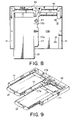
- FIG. 8 is a plan view of the card fitting mechanism in FIG. 7 after the first card is inserted therein;
- FIG. 9 is a perspective view of the card fitting mechanism in FIG. 8 when a second card is partly inserted after the first card is inserted;
- FIG. 10 is a plan view of the card fitting mechanism in FIG. 1 after a card of a different shape is inserted therein;
- FIG. 11 is a plan view of the card fitting mechanism in FIG. 10 when the card of the different shape is partly inserted.
- FIG. 12 is a perspective view of the card fitting mechanism in FIG. 11 after the card of the different shape is inserted therein.
- FIGS. 1 to 4 a card fitting mechanism according to an embodiment of the present invention will be described.
- the card fitting mechanism illustrated in the figure is adapted for receiving or setting cards 31 each having a plate-like shape, such as an IC card, and comprises a pair of guide frames 11 arranged in parallel to each other with a predetermined space, a base plate 13 supporting the guide frames 11 on its upper surface, a connector 15 having opposite ends held between ends of the guide frames 11 , and a guiding member 17 disposed on the base plate 13 between the guide frames 11 .
- the base plate 13 is mounted to an electronic apparatus (not shown). Specifically, the base plate 13 is fixed to a printed circuit board (not shown) mounted to the electronic apparatus by inserting screws into screw holes 11 b formed on the guide frames 11 , respectively. An upper space defined on the base plate 13 is separated by the guiding member 17 between the guide frames 11 into a first card receiving portion 13 a and a second card receiving portion 13 b . Onto the upper surface of the base plate 13 , the cards 31 are fitted with sliding movement in a predetermined sliding direction, i.e., a first direction A. Thus, the cards 31 are fitted to the first and the second card receiving portions 13 a and 13 b along the upper surface of the base plate 13 . In FIG. 2 , the cards 31 are identical in shape and size and fitted in parallel to each other on left and right sides in the figure as depicted by imaginary lines.
- the connector 15 comprises an insulator 15 a and a plurality of conductive contacts 21 held in the insulator 15 a .
- Each of the contacts 21 has a contacting portion 21 a to be contacted with a card-side contacting portions (not shown) of the card 31 , a holding portion (not shown) held by the insulator 15 a , and a terminal portion 21 c extending from the holding portion to the outside of the insulator 15 a .
- the terminal portion 21 c is connected by soldering to a conductive portion formed on the above-mentioned printed circuit board. Since the connector 15 for connecting the card 31 is provided, the card fitting mechanism may be called a card connector.
- the guiding member 17 is located at a generally intermediate position between the first and the second card receiving portions 13 a and 13 b and rotatably supported on the base plate 13 through a shaft portion 41 .
- the guiding member 17 has a first guide portion 17 a and a second guide portion 17 b connected to the first guide portion 17 a .
- the guiding member 17 is designed as an assembly comprising a plurality of parts.
- the second guide portion 17 b is provided with a connecting shaft portion 44 extending in a direction perpendicular to the base plate 13 . To the connecting shaft portion 44 , the first guide portion 17 a and a first spring member 43 are rotatably fixed.
- the first and the second guide portions 17 a and 17 b are urged by the spring member 43 to be aligned in a single straight line.
- the first guide portion 17 a is rotatable with respect to the second guide portion 17 b .
- the first and the second guide portions 17 a and 17 b are aligned along a single straight line under urging force of the spring member 43 .
- the second guide portion 17 b is supported by the shaft portion 41 of the base plate 13 to be rotatable in second and third directions B and C.
- the second guide portion 17 b has an extended portion extending to a rear side of the connector 15 and provided with a spring fixing portion 17 c .
- the spring fixing portion 17 c is engaged with one of hooks of a second spring member, namely, a tension coil spring 49 .
- the other hook of the tension coil spring 49 is engaged with an engaging part 13 c of the base plate 13 .
- the guiding member 17 is urged in the third direction C around the shaft portion 41 .
- the guiding member 17 is rotated in the third direction C around the shaft portion 41 and located at a right-hand position in the figure. Therefore, the first guide portion 17 a is located in the second card receiving portion 13 b.
- the base plate 13 is provided with first and second stopper portions 45 and 46 for fixing the first guide portion 17 a .
- first guide portion 17 a When an end portion of the first guide portion 17 a is engaged with the first stopper portion 45 as depicted by a solid line in FIG. 1 , the first guide portion 17 a is fixed to be aligned with the second guide portion 17 b in a single straight line.
- the first guide portion 17 a When the end portion of the first guide portion 17 a is engaged with the second stopper portion 46 as depicted by a dot-and-dash line in FIG. 1 , the first guide portion 17 a is fixed to be perpendicular to the second guide portion 17 b.
- the first guide portion 17 a is engaged with the first stopper portion 45 . Therefore, the card 31 partly inserted into the second card receiving portion 13 b is engaged with the first guide portion 17 a and inhibited from further insertion. Thus, the card 31 can be inserted only into the first card receiving portion 13 a.
- the second guide portion 17 b is pressed by the card 31 and rotated in the second direction B against the tension coil spring 49 .
- the guiding member 17 is parallel to the first direction A so that the card 31 can be inserted into the second card receiving portion 13 b . Therefore, two cards same in shape and size can be fitted as illustrated in FIG. 2 .
- the guide frames 11 have inward surfaces faced to each other and provided with frame guide grooves 11 a for guiding insertion and removal of the cards 31 , respectively.
- the guiding member 17 is provided with a pair of guide grooves 17 d for guiding removal of the cards 31 . It is noted here that, when a first card 31 is inserted into the first card receiving portion 13 a , one of the guide grooves 17 d of the guiding member 17 serves to guide insertion of a second card 31 into the second card receiving portion 13 b.
- the first and the second card receiving portions 13 a and 13 b are given degrees of priority by the guiding member 17 .
- the guiding member 17 is rotated in the third direction C and rests in an opened state.
- the second card 31 is inserted into the second card receiving portion 13 b as illustrated in FIG. 9 .
- the second card 31 is guided by the frame guide groove 11 a of one of the guide frames 11 and one of the guide grooves 17 d of the guiding member 17 .
- the card contacting portions of the second card 31 are contacted with the contacts 21 of the connector.
- a card 51 of an irregular shape may be inserted.
- the first guide portion 17 a When the card 51 is inserted, the first guide portion 17 a is rotated along the shape of the card 51 .
- an end of the card 51 is brought into contact with the second guide portion 17 b as illustrated in FIG. 11 .
- the second guide portion 17 b starts rotation in the second direction B.
- the first guide portion 17 a is dragged by the second guide portion 17 b .
- the first guide portion 17 a is released from engagement by the first stopper portion 45 .
- a step portion 51 c on an outer contour of the card 51 is brought into contact with the first guide portion 17 a .
- the first guide portion 17 a is rotated in the third direction C against urging force of the spring member 43 to be engaged with the second stopper portion 46 .
- the guiding member 17 takes a form along the outer contour of the card 51 as illustrated in FIG. 12 . As described above, even if the card 51 has such an irregular shape, the guiding member 17 is bent in conformity with the shape of the card 51 so as to allow the card 51 to be fitted.
- the guiding member 17 returns to its initial position under the action of the tension coil spring 49 and the spring member 43 .
- the guiding member 17 is returned to the uninserted state under the restoring force of the tension coil spring 49 and the spring member 43 after the card 31 or 51 is removed.
- the guide frames are formed on the base plate 13 .
- the guide frames and the base plate 13 may be reversed in position in a vertical direction.
- the card fitting mechanism mentioned above is applicable to various apparatuses, such as a PDA (Personal Digital Assistant) or a mobile telephone, adapted to use a SD (Secure Digital) memory card, a memory stick, a disk card, or the like as a memory.
- PDA Personal Digital Assistant
- SD Secure Digital
- the present invention has thus far been described in conjunction with the preferred embodiment thereof, it will be readily possible for those skilled in the art to put the present invention into practice in various other manners without departing from the scope of the present invention.
- the card fitting mechanism may be designed to have three or more card receiving portions.
- the guiding member is disposed each between adjacent ones of the card receiving portions.
Abstract
Description
Claims (7)
Applications Claiming Priority (2)
| Application Number | Priority Date | Filing Date | Title |
|---|---|---|---|
| JP2003311703A JP3812946B2 (en) | 2003-09-03 | 2003-09-03 | Card mounting mechanism |
| JP311703/2003 | 2003-09-03 |
Publications (2)
| Publication Number | Publication Date |
|---|---|
| US20050048833A1 US20050048833A1 (en) | 2005-03-03 |
| US7108530B2 true US7108530B2 (en) | 2006-09-19 |
Family
ID=34214264
Family Applications (1)
| Application Number | Title | Priority Date | Filing Date |
|---|---|---|---|
| US10/930,396 Expired - Fee Related US7108530B2 (en) | 2003-09-03 | 2004-08-31 | Card fitting mechanism having a plurality of card receiving portions and yet capable of being reduced in size |
Country Status (5)
| Country | Link |
|---|---|
| US (1) | US7108530B2 (en) |
| JP (1) | JP3812946B2 (en) |
| KR (1) | KR100681650B1 (en) |
| CN (1) | CN1294681C (en) |
| TW (1) | TWI268015B (en) |
Cited By (21)
| Publication number | Priority date | Publication date | Assignee | Title |
|---|---|---|---|---|
| US20080166897A1 (en) * | 2007-01-05 | 2008-07-10 | Jonathan Hubert | Expandable and collapsible peripheral device |
| US20080166898A1 (en) * | 2007-01-05 | 2008-07-10 | Jonathan Hubert | Method of making an expandable and collapsible peripheral device |
| US20090004921A1 (en) * | 2007-06-29 | 2009-01-01 | Jonathan Hubert | Adapter system for use with an expresscard slot |
| US20090006682A1 (en) * | 2007-06-29 | 2009-01-01 | Jonathan Hubert | Method of adapting an expresscard slot for smaller form factor memory compatibility |
| US20090006681A1 (en) * | 2007-06-29 | 2009-01-01 | Jonathan Hubert | Dual bus expresscard peripheral device |
| US20090004920A1 (en) * | 2007-06-29 | 2009-01-01 | Jonathan Hubert | Method of adapting an expresscard slot for use with portable memory cards |
| US20090006698A1 (en) * | 2007-06-29 | 2009-01-01 | Jonathan Hubert | Adapter for an expresscard slot |
| US20090002933A1 (en) * | 2007-06-29 | 2009-01-01 | Jonathan Hubert | Memory card for an expresscard slot |
| US20090006707A1 (en) * | 2007-06-29 | 2009-01-01 | Jonathan Hubert | Method of using the dual bus interface in an expresscard slot |
| US20110005068A1 (en) * | 2009-07-08 | 2011-01-13 | Hong Fu Jin Precission Industry (Shenzhen) Co., Ltd. | Fixing apparatus for storage device |
| US8589608B2 (en) | 2011-02-26 | 2013-11-19 | International Business Machines Corporation | Logic node connection system |
| US8597032B2 (en) | 2011-02-26 | 2013-12-03 | International Business Machines Corporation | Electronic assemblies mating system |
| US8713228B2 (en) | 2011-02-26 | 2014-04-29 | International Business Machines Corporation | Shared system to operationally connect logic nodes |
| US8738828B2 (en) | 2011-02-26 | 2014-05-27 | International Business Machines Corporation | System to operationally connect logic nodes |
| US9652001B2 (en) * | 2015-08-18 | 2017-05-16 | Hon Hai Precision Industry Co., Ltd. | Carrier for hard disk drive |
| US10063001B2 (en) * | 2016-09-23 | 2018-08-28 | Apple Inc. | Gated connector receptacles |
| US20190098789A1 (en) * | 2017-09-25 | 2019-03-28 | Dell Products, Lp | Information Handling System with an Adjustable Guide for Peripheral Cards |
| US10374362B2 (en) | 2017-06-05 | 2019-08-06 | Apple Inc. | Integrated protector for a connector |
| US10546616B2 (en) * | 2018-01-30 | 2020-01-28 | Quanta Computer Inc. | Adjustable storage device carrier |
| US11158965B2 (en) * | 2019-08-23 | 2021-10-26 | Wistron Corp. | Connecting module and electronic device |
| US11337329B2 (en) * | 2020-06-24 | 2022-05-17 | Dell Products, L.P. | Single-blade air damper for rack-mounted chassis |
Families Citing this family (4)
| Publication number | Priority date | Publication date | Assignee | Title |
|---|---|---|---|---|
| CN103428313B (en) | 2012-05-21 | 2016-02-10 | 中兴通讯股份有限公司 | A kind of client identification module card compatible apparatus and terminal equipment |
| US9246249B2 (en) * | 2014-05-14 | 2016-01-26 | Proconn Technology Co., Ltd. | Card connector for different specifications of electronic cards |
| JP6463943B2 (en) * | 2014-10-24 | 2019-02-06 | 株式会社東芝 | Anti-vibration structure for electronic equipment with auxiliary storage device |
| KR101666851B1 (en) * | 2015-03-05 | 2016-10-17 | (주)우주일렉트로닉스 | Connector System for Preventing Mixing of Tray |
Citations (8)
| Publication number | Priority date | Publication date | Assignee | Title |
|---|---|---|---|---|
| US5017147A (en) * | 1989-05-15 | 1991-05-21 | Yazaki Corporation | Connectors with cover providing connection sequence control |
| JPH087047A (en) | 1994-06-23 | 1996-01-12 | Casio Comput Co Ltd | Card discharging mechanism and electronic device provided with this |
| US5848906A (en) * | 1997-02-07 | 1998-12-15 | Silicon Graphics, Inc. | Loading and placement device for connecting circuit boards |
| US6419499B1 (en) * | 2000-08-01 | 2002-07-16 | Alcatel Canada Inc. | Apparatus for electronically interconnecting electronic circuit substrates |
| JP2002318511A (en) | 2001-04-23 | 2002-10-31 | Casio Electronics Co Ltd | Consumable with function of discriminating recycled state and image forming device |
| JP2002329178A (en) | 2001-04-27 | 2002-11-15 | Itt Cannon Ltd | Card holder to which two or more cards can be inserted |
| US6483717B1 (en) * | 2000-05-02 | 2002-11-19 | Hewlett-Packard Company | Switch integral to a latch assembly |
| US6814606B2 (en) * | 2002-11-08 | 2004-11-09 | Sumitomo Wiring Systems, Ltd. | Electrical connector locking system |
Family Cites Families (5)
| Publication number | Priority date | Publication date | Assignee | Title |
|---|---|---|---|---|
| JPH088538Y2 (en) * | 1990-01-23 | 1996-03-06 | シャープ株式会社 | IC card ejector |
| JP3023765B2 (en) | 1996-06-18 | 2000-03-21 | 日本航空電子工業株式会社 | Card-like electronic devices |
| CN2454918Y (en) * | 2000-12-25 | 2001-10-17 | 富士康(昆山)电脑接插件有限公司 | Electronic-card connector |
| JP3948938B2 (en) * | 2001-11-13 | 2007-07-25 | アルプス電気株式会社 | Card connector device |
| JP3824147B2 (en) * | 2001-12-21 | 2006-09-20 | タイコエレクトロニクスアンプ株式会社 | Card connector |
-
2003
- 2003-09-03 JP JP2003311703A patent/JP3812946B2/en not_active Expired - Fee Related
-
2004
- 2004-08-31 US US10/930,396 patent/US7108530B2/en not_active Expired - Fee Related
- 2004-08-31 CN CNB2004100683368A patent/CN1294681C/en not_active Expired - Fee Related
- 2004-09-02 TW TW093126455A patent/TWI268015B/en not_active IP Right Cessation
- 2004-09-02 KR KR1020040069770A patent/KR100681650B1/en not_active IP Right Cessation
Patent Citations (8)
| Publication number | Priority date | Publication date | Assignee | Title |
|---|---|---|---|---|
| US5017147A (en) * | 1989-05-15 | 1991-05-21 | Yazaki Corporation | Connectors with cover providing connection sequence control |
| JPH087047A (en) | 1994-06-23 | 1996-01-12 | Casio Comput Co Ltd | Card discharging mechanism and electronic device provided with this |
| US5848906A (en) * | 1997-02-07 | 1998-12-15 | Silicon Graphics, Inc. | Loading and placement device for connecting circuit boards |
| US6483717B1 (en) * | 2000-05-02 | 2002-11-19 | Hewlett-Packard Company | Switch integral to a latch assembly |
| US6419499B1 (en) * | 2000-08-01 | 2002-07-16 | Alcatel Canada Inc. | Apparatus for electronically interconnecting electronic circuit substrates |
| JP2002318511A (en) | 2001-04-23 | 2002-10-31 | Casio Electronics Co Ltd | Consumable with function of discriminating recycled state and image forming device |
| JP2002329178A (en) | 2001-04-27 | 2002-11-15 | Itt Cannon Ltd | Card holder to which two or more cards can be inserted |
| US6814606B2 (en) * | 2002-11-08 | 2004-11-09 | Sumitomo Wiring Systems, Ltd. | Electrical connector locking system |
Cited By (33)
| Publication number | Priority date | Publication date | Assignee | Title |
|---|---|---|---|---|
| US7762849B2 (en) | 2007-01-05 | 2010-07-27 | Sandisk Corporation | Expandable and collapsible peripheral device |
| US20080166898A1 (en) * | 2007-01-05 | 2008-07-10 | Jonathan Hubert | Method of making an expandable and collapsible peripheral device |
| US20080191032A1 (en) * | 2007-01-05 | 2008-08-14 | Sandisk Corporation | Expandable and collapsible peripheral device |
| US20080166897A1 (en) * | 2007-01-05 | 2008-07-10 | Jonathan Hubert | Expandable and collapsible peripheral device |
| US7798840B2 (en) | 2007-01-05 | 2010-09-21 | Sandisk Corporation | Expandable and collapsible peripheral device |
| US20090002933A1 (en) * | 2007-06-29 | 2009-01-01 | Jonathan Hubert | Memory card for an expresscard slot |
| US20100173517A1 (en) * | 2007-06-29 | 2010-07-08 | Jonathan Hubert | Memory card for an expresscard slot |
| US20090006698A1 (en) * | 2007-06-29 | 2009-01-01 | Jonathan Hubert | Adapter for an expresscard slot |
| US8561295B2 (en) | 2007-06-29 | 2013-10-22 | Sandisk Technologies Inc. | Method of adapting an expresscard slot for smaller form factor memory compatibility |
| US20090006707A1 (en) * | 2007-06-29 | 2009-01-01 | Jonathan Hubert | Method of using the dual bus interface in an expresscard slot |
| US7686654B2 (en) | 2007-06-29 | 2010-03-30 | Sandisk Corporation | Memory card for an ExpressCard slot |
| US7699660B2 (en) | 2007-06-29 | 2010-04-20 | Sandisk Corporation | Adapter for an expresscard slot |
| US20090004920A1 (en) * | 2007-06-29 | 2009-01-01 | Jonathan Hubert | Method of adapting an expresscard slot for use with portable memory cards |
| US20090006681A1 (en) * | 2007-06-29 | 2009-01-01 | Jonathan Hubert | Dual bus expresscard peripheral device |
| US7779184B2 (en) | 2007-06-29 | 2010-08-17 | Sandisk Corporation | Method of using the dual bus interface in an expresscard slot |
| US20090006682A1 (en) * | 2007-06-29 | 2009-01-01 | Jonathan Hubert | Method of adapting an expresscard slot for smaller form factor memory compatibility |
| US20090004921A1 (en) * | 2007-06-29 | 2009-01-01 | Jonathan Hubert | Adapter system for use with an expresscard slot |
| US8051229B2 (en) | 2007-06-29 | 2011-11-01 | Sandisk Technologies Inc. | Dual bus ExpressCard peripheral device |
| US8092257B2 (en) | 2007-06-29 | 2012-01-10 | Sandisk Technologies Inc. | Memory card for an expresscard slot |
| US20110005068A1 (en) * | 2009-07-08 | 2011-01-13 | Hong Fu Jin Precission Industry (Shenzhen) Co., Ltd. | Fixing apparatus for storage device |
| US8406003B2 (en) * | 2009-07-08 | 2013-03-26 | Hong Fu Jin Precision Industry (Shenzhen) Co., Ltd. | Fixing apparatus for storage device |
| US8589608B2 (en) | 2011-02-26 | 2013-11-19 | International Business Machines Corporation | Logic node connection system |
| US8597032B2 (en) | 2011-02-26 | 2013-12-03 | International Business Machines Corporation | Electronic assemblies mating system |
| US8713228B2 (en) | 2011-02-26 | 2014-04-29 | International Business Machines Corporation | Shared system to operationally connect logic nodes |
| US8738828B2 (en) | 2011-02-26 | 2014-05-27 | International Business Machines Corporation | System to operationally connect logic nodes |
| US9652001B2 (en) * | 2015-08-18 | 2017-05-16 | Hon Hai Precision Industry Co., Ltd. | Carrier for hard disk drive |
| US10063001B2 (en) * | 2016-09-23 | 2018-08-28 | Apple Inc. | Gated connector receptacles |
| US10374362B2 (en) | 2017-06-05 | 2019-08-06 | Apple Inc. | Integrated protector for a connector |
| US20190098789A1 (en) * | 2017-09-25 | 2019-03-28 | Dell Products, Lp | Information Handling System with an Adjustable Guide for Peripheral Cards |
| US10721835B2 (en) * | 2017-09-25 | 2020-07-21 | Dell Products, L.P. | Information handling system with an adjustable guide for peripheral cards |
| US10546616B2 (en) * | 2018-01-30 | 2020-01-28 | Quanta Computer Inc. | Adjustable storage device carrier |
| US11158965B2 (en) * | 2019-08-23 | 2021-10-26 | Wistron Corp. | Connecting module and electronic device |
| US11337329B2 (en) * | 2020-06-24 | 2022-05-17 | Dell Products, L.P. | Single-blade air damper for rack-mounted chassis |
Also Published As
| Publication number | Publication date |
|---|---|
| KR100681650B1 (en) | 2007-02-09 |
| JP2005078597A (en) | 2005-03-24 |
| TW200522446A (en) | 2005-07-01 |
| KR20050024245A (en) | 2005-03-10 |
| TWI268015B (en) | 2006-12-01 |
| US20050048833A1 (en) | 2005-03-03 |
| CN1294681C (en) | 2007-01-10 |
| JP3812946B2 (en) | 2006-08-23 |
| CN1591994A (en) | 2005-03-09 |
Similar Documents
| Publication | Publication Date | Title |
|---|---|---|
| US7108530B2 (en) | Card fitting mechanism having a plurality of card receiving portions and yet capable of being reduced in size | |
| US6700788B2 (en) | Connector device for cards permitting insertion of different types of cards | |
| US5846095A (en) | Edge card connector with alignment member | |
| JP3306831B2 (en) | Small card docking connector | |
| US5779494A (en) | Connector with reinforced latch | |
| JPH0869836A (en) | Card edge type connector | |
| US6902407B2 (en) | Contacting structure of a card connector | |
| US7452241B2 (en) | Card connector | |
| US7371089B2 (en) | Memory card connector with improved foldable baffler | |
| US7887334B2 (en) | Board connecting connector with board holding device | |
| US20030017732A1 (en) | Electrical card connector having polarization mechanism | |
| US7938651B2 (en) | Substrate connector | |
| JP4108048B2 (en) | Card connector | |
| US7618272B2 (en) | Electrical card connector with a dustproof device | |
| US20060057893A1 (en) | Card connector prevented from short-circuiting between a ground line and a signal line | |
| US5860825A (en) | Socket for printed circuit board | |
| US6146177A (en) | Electrical connector having a locking device | |
| US6338650B1 (en) | Rotatable card connector | |
| JP4184251B2 (en) | Card connector | |
| US6145747A (en) | Memory card and card connector and assembly thereof | |
| EP0214762A2 (en) | Cassette connector with pivot mechanism | |
| US20090221184A1 (en) | Card Connector | |
| WO2007146169A2 (en) | Card connector | |
| US7533825B2 (en) | Electronic apparatus which requires less space for loading and unloading an object | |
| JP2001155829A (en) | Card edge connector |
Legal Events
| Date | Code | Title | Description |
|---|---|---|---|
| AS | Assignment |
Owner name: JAPAN AVIATION ELECTRONICS INDUSTRY, LIMITED, JAPA Free format text: ASSIGNMENT OF ASSIGNORS INTEREST;ASSIGNORS:KIMURA, AKIRA;KAMATA, KAZUSHI;KATO, NOBUKAZU;AND OTHERS;REEL/FRAME:015762/0611;SIGNING DATES FROM 20040820 TO 20040824 Owner name: JAE HIROSAKI, LTD., JAPAN Free format text: ASSIGNMENT OF ASSIGNORS INTEREST;ASSIGNORS:KIMURA, AKIRA;KAMATA, KAZUSHI;KATO, NOBUKAZU;AND OTHERS;REEL/FRAME:015762/0611;SIGNING DATES FROM 20040820 TO 20040824 |
|
| CC | Certificate of correction | ||
| AS | Assignment |
Owner name: JAPAN AVIATION ELECTRONICS INDUSTRY, LIMITED, JAPA Free format text: ASSIGNMENT OF ASSIGNORS INTEREST;ASSIGNOR:JAE HIROSAKI, LTD.;REEL/FRAME:021439/0015 Effective date: 20080825 Owner name: JAPAN AVIATION ELECTRONICS INDUSTRY, LIMITED, JAPA Free format text: ASSIGNMENT OF ASSIGNORS INTEREST;ASSIGNOR:JAE HIROSAKI, LTD.;REEL/FRAME:021439/0012 Effective date: 20080825 |
|
| REMI | Maintenance fee reminder mailed | ||
| LAPS | Lapse for failure to pay maintenance fees | ||
| STCH | Information on status: patent discontinuation |
Free format text: PATENT EXPIRED DUE TO NONPAYMENT OF MAINTENANCE FEES UNDER 37 CFR 1.362 |
|
| FP | Lapsed due to failure to pay maintenance fee |
Effective date: 20100919 |