US7099112B1 - Balance ring - Google Patents
Balance ring Download PDFInfo
- Publication number
- US7099112B1 US7099112B1 US10/850,137 US85013704A US7099112B1 US 7099112 B1 US7099112 B1 US 7099112B1 US 85013704 A US85013704 A US 85013704A US 7099112 B1 US7099112 B1 US 7099112B1
- Authority
- US
- United States
- Prior art keywords
- disk
- balance ring
- protuberances
- balance
- center
- Prior art date
- Legal status (The legal status is an assumption and is not a legal conclusion. Google has not performed a legal analysis and makes no representation as to the accuracy of the status listed.)
- Expired - Fee Related
Links
- 238000009966 trimming Methods 0.000 claims description 13
- 230000007246 mechanism Effects 0.000 claims description 2
- 230000003287 optical effect Effects 0.000 claims description 2
- 238000000034 method Methods 0.000 abstract description 17
- 239000000758 substrate Substances 0.000 description 26
- 239000000463 material Substances 0.000 description 11
- 239000011521 glass Substances 0.000 description 10
- 238000004519 manufacturing process Methods 0.000 description 9
- 230000008878 coupling Effects 0.000 description 4
- 238000010168 coupling process Methods 0.000 description 4
- 238000005859 coupling reaction Methods 0.000 description 4
- 230000020347 spindle assembly Effects 0.000 description 4
- 238000002679 ablation Methods 0.000 description 3
- 230000008901 benefit Effects 0.000 description 3
- 239000004033 plastic Substances 0.000 description 3
- 229920003023 plastic Polymers 0.000 description 3
- VYPSYNLAJGMNEJ-UHFFFAOYSA-N Silicium dioxide Chemical compound O=[Si]=O VYPSYNLAJGMNEJ-UHFFFAOYSA-N 0.000 description 2
- 229910052782 aluminium Inorganic materials 0.000 description 2
- XAGFODPZIPBFFR-UHFFFAOYSA-N aluminium Chemical compound [Al] XAGFODPZIPBFFR-UHFFFAOYSA-N 0.000 description 2
- 239000013590 bulk material Substances 0.000 description 2
- 229910052751 metal Inorganic materials 0.000 description 2
- 239000002184 metal Substances 0.000 description 2
- 125000006850 spacer group Chemical group 0.000 description 2
- 230000002411 adverse Effects 0.000 description 1
- 239000005354 aluminosilicate glass Substances 0.000 description 1
- 239000005388 borosilicate glass Substances 0.000 description 1
- 239000000919 ceramic Substances 0.000 description 1
- 229910003460 diamond Inorganic materials 0.000 description 1
- 239000010432 diamond Substances 0.000 description 1
- 230000000694 effects Effects 0.000 description 1
- 238000002347 injection Methods 0.000 description 1
- 239000007924 injection Substances 0.000 description 1
- 238000001746 injection moulding Methods 0.000 description 1
- 150000002739 metals Chemical class 0.000 description 1
- 238000012986 modification Methods 0.000 description 1
- 230000004048 modification Effects 0.000 description 1
- 239000002991 molded plastic Substances 0.000 description 1
- 229920000642 polymer Polymers 0.000 description 1
- 230000000644 propagated effect Effects 0.000 description 1
- 239000000377 silicon dioxide Substances 0.000 description 1
- 238000009987 spinning Methods 0.000 description 1
- 230000008685 targeting Effects 0.000 description 1
Images


Classifications
-
- G—PHYSICS
- G11—INFORMATION STORAGE
- G11B—INFORMATION STORAGE BASED ON RELATIVE MOVEMENT BETWEEN RECORD CARRIER AND TRANSDUCER
- G11B23/00—Record carriers not specific to the method of recording or reproducing; Accessories, e.g. containers, specially adapted for co-operation with the recording or reproducing apparatus ; Intermediate mediums; Apparatus or processes specially adapted for their manufacture
- G11B23/0014—Record carriers not specific to the method of recording or reproducing; Accessories, e.g. containers, specially adapted for co-operation with the recording or reproducing apparatus ; Intermediate mediums; Apparatus or processes specially adapted for their manufacture record carriers not specifically of filamentary or web form
- G11B23/0021—Record carriers not specific to the method of recording or reproducing; Accessories, e.g. containers, specially adapted for co-operation with the recording or reproducing apparatus ; Intermediate mediums; Apparatus or processes specially adapted for their manufacture record carriers not specifically of filamentary or web form discs
- G11B23/0028—Details
Definitions
- This invention relates to the field of disk drives and, more specifically, to mass balancing of disks for use in disk drive systems.
- a disk drive system typically consists of one or more magnetic recording disks and control mechanisms for storing data within approximately circular tracks on a disk.
- a disk is composed of a substrate and one or more layers deposited on the substrate. In most systems, an aluminum substrate is used. However, alternative substrate materials such as glass have various performance benefits such that it may be desirable to use a glass substrate.
- the material may be scribed to generate a substrate having an inner diameter (ID) and an outer diameter (OD).
- ID inner diameter
- OD outer diameter
- One method of generating a disk substrate is to laser scribe a controlled shape, such as a circle, into one surface (the scribe side) of a glass sheet to generate the ID and OD contours of the disk substrate. A fine crack is propagated along the contours during the laser scribing. After scribing, the disk-shaped substrate may be removed from the excess bulk material of the sheet by breaking the material along the scribed contours.
- the non-scribed side of the substrate may have a poorly defined diameter.
- the ID may result in inwardly or outwardly protruding spurs, as illustrated FIG. 1A , and sloping side walls. Spurs on the surface of the disk substrate adjacent the ID may be generated when the glass is fractured to remove the disk from excess bulk material. Also, the scribe lines have a tendency to overlap resulting in imperfections to the disk substrate.
- the radial deviation of the laser scribe may also result in a substrate having a non-circular ID, as illustrated in FIG. 1B .
- the ID imperfections may be especially problematic because the ID is mounted onto the spindle of the disk drive.
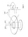
- Such disk substrate imperfections may result in a disk substrate that is not mass-balanced, as illustrated in FIG. 1C .
- the mass center may be at point A, while the rotational center (substantially the ID geometric center at which the disk rotates when mounted) may be at point B.
- a disk having this type of substrate may encounter balancing problems when rotated on the spindle of a disk drive system.
- the mass center of a substrate should be located at the rotational center at which the substrate rotates.
- a mass balanced disk is one in which the mass center of the disk equates to the rotational center of the disk.
- a mass balanced disk is functionally important, because newer disk drive systems require higher rotational speeds. A high rotational speed of an unbalanced disk may lead to poor performance or disk failure.
- proper balancing is also necessary to achieve high track density by enabling the read/write head to accurately follow data tracks on a disk.
- Another problem of disk substrate scribing results from the ID having a greater size than the drive spindle in order to fit properly over the disk drive spindle.
- a gap between the ID of the disk and the spindle diameter is present, as illustrated in FIG. 2 , causing the disk to be located eccentrically on the drive hub.
- off angle illustration of the disk in relation to the spindle is not meant to imply a loss of planarity but, rather, to highlight the gap between the disk ID and the spindle hub.
- the gap results in an offset between the disk's rotational center and the spindle's rotation center. If the ID were scribed to fit exactly around the spindle, the disk would most likely be in balance. However, because of manufacturing limitations, such precision may not be practical.
- the apparatus may include a substantially circular band having a top surface, a bottom surface, an inner diameter surface and an outer diameter surface.
- the outer diameter surface of the band may have one or more clamp structures disposed thereon to couple the band to a disk with each of the one or more clamp structures radially extended away from the outer diameter surface of the band.
- the inner diameter surface may have a plurality of protuberances disposed thereon.
- the method may include coupling the band to the ID of a disk and trimming the protuberances to establish a new rotational center of the coupled disk and band coincident with the mass center of the disk/band.
- FIG. 1A illustrates a disk manufacturing problem of an ID that has protruding spurs.
- FIG. 1B illustrates a disk manufacturing problem of an ID that is not circular.
- FIG. 1C illustrates a disk manufacturing problem of an ID that is not centered on the disk.
- FIG. 2 illustrates a problem of gaps forming between the ID of a disk and a spindle caused by variations in disk manufacturing.
- FIG. 3 illustrates a perspective view of one embodiment of a balance ring.
- FIG. 4 illustrates a top view of the balance ring of FIG. 3 .
- FIG. 5 illustrates a cross-sectional side view of the balance ring of FIG. 3 .
- FIG. 6A illustrates one embodiment of a balance ring inserted into the inner diameter space of a disk.
- FIG. 6B illustrates one embodiment of a balance ring expanded to be coupled with a disk.
- FIG. 6C illustrates one embodiment of a balance ring coupled with a disk after the loop structures of the balance ring have been trimmed.
- FIG. 7 illustrates a cross-sectional side view of yet another embodiment of a balance ring.
- FIG. 8A illustrates one embodiment of a balance ring and disk before trimming of the balance ring.
- FIG. 8B illustrates one embodiment of a balance ring and disk after the trimming of the balance ring.
- FIG. 9A illustrates one embodiment of a balance ring having loop structures for protuberances before trimming.
- FIG. 9B illustrates one embodiment of the balance ring of FIG. 9A after the loop structures have been trimmed.
- FIG. 10 illustrates one embodiment of a balance ring having a toggle clip.
- FIG. 11 illustrates one embodiment of a balance ring having a snap clip.
- FIG. 12 illustrates one embodiment of a spindle assembly having balanced disks.
- FIG. 13 illustrates one embodiment of a disk drive having a mass balance disk.
- FIG. 14 illustrates one embodiment of a disk balancing system.
- the apparatus and methods discussed herein may be used with various types of disks.
- the apparatus and methods discussed herein may be used with a magnetic recording disk.
- the apparatus and methods discussed herein may be used with other types of digital recording disks, for examples, a compact disc (CD) and a digital video disk (DVD).
- CD compact disc
- DVD digital video disk
- the apparatus and method described herein may be implemented with a glass substrate.
- Glass substrates that may be used include, for example, a silica containing glass such as borosilicate glass an aluminosilicate glass. It should be noted that the description of the apparatus and method in relation to a glass substrate is only for illustrative purposes and is not meant to be limited only to the balancing of glass substrates. In an alternative embodiment, other substrate materials including polymers, ceramics, and metals such as aluminum may be used.
- the method may include coupling a balance ring to the ID of a disk.
- the balance ring may be substantially circular in shape and have protuberances along its inner diameter.
- One or more clamp structures may be disposed on the outer diameter of the balance ring that extends outwardly to couple the balance ring to the ID of a disk.
- the disk, with the coupled balance ring may be placed on a mass balancing machine to determine a new mass center of the disk. It should be noted that the mass of the balance ring may be negligible relative to the mass of the disk. As such, at times, reference may be made only to the mass center of a disk. However, such reference is intended to include the mass of the balance ring when it is coupled to the disk.
- the mass balance point on the disk may not be the same as to the rotational center of the disk.
- the protuberances on the balance ring may be trimmed to align the rotational center of the disk with the new mass center of the disk coupled with the trimmed balance ring. Trimming the protuberances may be achieved, for example, through the use of laser energy or thermal ablation. In another embodiment, the trimming of the protuberances may be achieved through mechanical means.
- the trimmed protuberances occupy the space between the ID of the disk and a disk drive spindle. Minimizing the space between the ID of a disk and a disk drive spindle inhibits operational failures associated with the disk spinning eccentrically.
- the balance ring allows for a disk to be scribed without precision with respect to the size of the ID or OD, because the balance ring may be trimmed to provide an exact fit between the spindle and the disk, as well as mass balancing the disk.
- the balance ring may provide a very cost effective and simple way to mass balance a disk.
- FIG. 3 illustrates a perspective view
- FIG. 4 illustrates a top view of one embodiment of a balance ring.
- Balance ring 300 is a band having a closed and substantially circular structure. The band is continuous as shown, but does not necessarily have to possess that limitation.
- Balance ring 300 has inner diameter surface 310 having an inner diameter, outer diameter surface 312 having an outer diameter, top surface 314 and bottom surface 316 .
- Balance ring 300 also includes clamp structures along outer diameter surface 312 .
- the clamp structures are pairs of flanges 320 – 322 (only a single flange of the pair shown for flange pair 322 of FIG. 3 and for the flange pairs illustrated in the top perspective of FIG. 4 ) that extend outwardly from top surface 314 and bottom surface 316 of balance ring 300 .
- Each flange of flange pairs 320 – 322 has a circumferential length 319 to secure an ID of a disk (not shown) to the balance ring 300 .
- Flange pairs 320 – 322 may also operate to prevent balance ring 300 from slipping through the ID of a disk.
- balance ring 300 may include more or less than three clamp structures, for example, a single flange pair may extend around the entire periphery of balance ring 300 .
- balance ring 300 includes three protuberances 330 – 332 along inner diameter surface 310 .
- Protuberances 330 – 332 extend inwardly from inner diameter surface 310 of balance ring 300 .
- protuberances 330 – 332 and flange pairs 320 – 322 are displaced at the same radial locations of balance ring 300 , with the sum of the angles between each of the protuberances (and, hence, each of the flange pairs) being greater than 180 degrees.
- Protuberances 330 – 332 are displaced along inner diameter surface 310 and flange pairs 320 – 322 are displaced along outer diameter surface 312 .
- protuberances 330 – 332 may be positioned anywhere along inner diameter 310 of balance ring 300 .
- protuberances 330 – 332 may be displaced at locations different from flange pairs 320 – 322 .
- balance ring 300 may have more than three protuberances.
- protuberances 330 – 332 have tab-like shapes. It should be noted that other shapes for protuberances 330 – 332 may be used, for examples, circular and triangular. As long as protuberances 330 – 332 have protruding features that provide sufficient material to mechanically strength and stabilize coupling to the disk, balance ring 300 may be utilized to mass balance a disk.
- balance ring 300 With balance ring 300 is coupled to a disk, a mass center of the disk/balance ring may be determined. After the mass center of the disk with coupled balance ring 300 is determined, protuberances 320 – 322 may be trimmed to mass balance the disk so that the rotational center of the disk/balance ring is coincident with the mass center of the disk/balance ring 300 combination.
- balance ring 300 may also include protuberances disposed on the outer diameter surface 312 , for example, protuberances 460 – 462 .
- Protuberances 460 – 462 may be disposed at approximately the same circumferential positions as protuberances 330 – 332 or, alternatively, at other positions along outer diameter surface 312 .
- Protuberances 460 – 462 operate to provide a secure fit between balance ring 300 and an ID of a disk.
- more or less than three protuberances on the outer surface of the balance ring may be used to provide more or less than three points of contact between balance ring 300 and a disk.
- a single point of contact may be provided by injection molding balance ring 300 to a disk.
- a slight relief may be grooved along outer diameter surface 312 of balance ring 300 to provide a secure fit with an ID of a disk.
- FIG. 5 illustrates a cross-sectional side view of the balance ring of FIG. 3 .
- This view crosses through a flange pair, a band, an inner diameter protuberance and an outer diameter protuberance.
- Balance ring 500 has inner diameter surface 510 , outer diameter surface 512 , top surface 514 , bottom surface 516 , flange pair 520 , inner diameter protuberance 530 , outer diameter protuberance 560 , and band 540 .
- Protuberance 530 extends radially toward a center of balance ring 500 .
- Flange pair 520 extends radially from outer diameter 512 .
- Balance ring 500 is configured such that an ID of a disk fits in the space within height h 1 of outer diameter surface 512 .
- flange pair 520 and protuberance 530 may be integrally formed with band 540 .
- balance ring 500 has flange pair 520 and protuberance 530 that may be flexibly attached to band 540 .
- Flange pair 520 assists in maintaining a continuous contact between outer diameter surface 512 of balance ring 500 and the ID of a disk, while preventing balance ring 500 from slipping through the ID of the disk.
- balance ring 500 has a thickness h 2 formed by outer diameter surface 512 and top surface 514 and a thickness h 3 formed by outer diameter surface 512 and bottom surface 516 . Thickness h 2 and thickness h 3 add to the total thickness of a disk when balance ring 500 is coupled to the disk.
- outer diameter surface 512 is substantially vertical and approximately equal to the thickness of a disk to which balance ring 500 is to be coupled.
- the outer diameter surface 512 may have other edge shapes, for example, a curved shape.
- FIG. 7 illustrates yet another embodiment of a balance ring.
- edge portions 770 of the ID surface of disk 760 may be chamfered inwardly towards outer diameter surface 712 of balance ring 700 .
- both the inner diameter surface 712 of balance ring 700 and disk 760 may have substantially the same thickness h 3 .
- the inner surface 712 may be secured at other positions along the chamfered edges portions 770 such that the height of inner diameter surface 712 is less than the thickness of disk 760 .
- This embodiment has the advantage of not having to modify the structure of a clamp so as to be disposed on top surfaces 714 and 764 of balance ring 700 and disk 760 , respectively. As such, balance ring 700 may be easily incorporated into the assembly of a disk drive system.
- FIGS. 8A and 8B illustrate an embodiment of the present invention in which a balance ring is coupled to a disk.
- FIG. 8A is a top view illustrating balance ring 800 and disk 840 .
- Flange pairs 820 – 822 secure balance ring 800 to ID 850 of disk 840 .
- Protuberances 830 – 832 extend inwardly from balance ring 800 .
- This embodiment shows disk 840 before it is balanced by trimming protuberances 830 – 832 .
- FIG. 8B shows disk 840 after it is balanced. Protuberances 830 – 832 have been trimmed. In addition to realigning to rotational center to the mass center of disk 840 (coupled with the balance ring), balancing ring 800 also operates to fill part or all of a gap formed between the inner diameter of the disk 840 and a disk drive spindle.
- FIG. 9A illustrates a perspective view of an embodiment of a balance ring with an alternative protuberance structure.
- the protuberances on balance ring 900 are formed as closed loops 930 – 932 .
- the loops 930 – 932 extend from the hinges 940 – 942 of balance ring 900 .
- Hinges 940 – 942 , 933 – 935 , and 920 – 922 may be integrated with balance ring 900 and are shown in a collapsed state.
- Hinges 940 – 942 , 933 – 935 , and 920 – 922 operate to alter the structure of balance ring 900 so that it may be inserted within the ID of the disk (illustrated in FIG. 6A ) and then expanded to be coupled with a disk (illustrated in FIG. 6B ).
- Such a hinge structure may be referred to as a “living hinge.”
- FIG. 9B illustrates the living hinge balance ring after the protuberances have been trimmed to mass balance a disk.
- Loops 930 – 932 of FIG. 9A when trimmed, become open structures having contact areas.
- loop 930 of FIG. 9A when trimmed has two contact areas 950 and 951 with a disk spindle.
- balance ring 900 has three loops 930 – 932 of FIG. 9A that, when trimmed, provide 6 areas of contact 950 – 955 .
- Such protuberances operate to align the mass center of the disk, to which balance ring 900 is coupled (as illustrated in FIG. 6C ), with the rotational center of the disk when the combination is rotated on a drive spindle.
- loops 930 – 932 may be open loops such that a segment of the loop may be omitted.
- an open loop may have a form similar to the post-trimming, open structures illustrated in FIG. 9B .
- FIG. 10 illustrates a perspective and partial cross-sectional view of a balance ring having an alternative protuberance structure.
- Balance ring 1000 includes annular ring 1010 within a circumference of balance ring 1000 . Notch 1020 along balance ring 1000 expose a portion of annular ring 1010 .
- Annular ring 1010 operates as a torsion beam such that the protuberances flex about annular ring 1010 .
- each exposed portion of annular ring 1010 may be a separate pin member.
- the protuberances are formed with clamp structures 1030 having top surface 1032 that extends past a circumferential thickness of balance ring 1000 and is also angled downward towards the center of balance ring 1000 . Angled portion 1036 of top surface 1032 may be trimmed to balance a disk.
- the clip portion 1034 on top surface 1032 of clamp structure 1030 couples balance ring 1000 to one side of a disk.
- Clamp structures 1030 also include a heal portion 1039 disposed below the center of moment of annular ring 1010 in order to restraint the clip portion 1034 against the disk.
- flanges 1040 and 1041 extend towards a disk. As such, clip portion 1034 and flanges 1040 and 1041 secure balance ring 1000 to a disk.
- This embodiment is referred to as the “toggle clip” design.
- clamp structure 1030 is rotated about its supporting element(s) axis or toggled downward towards bottom surface 1050 balance ring 1000 until top surface 1032 is parallel with inner diameter 1060 of balance ring 1000 .
- This position provides enough clearance for balance ring 1000 to be inserted along an ID of a disk.
- Flanges 1040 and 1041 extending from bottom surface 1050 of balance ring 1000 is pushed flush against the corresponding surface of a disk.
- Clamp structure 1030 may then be toggled upwards so that clip portion 1034 couples to a surface of a disk opposite the side in contact with flanges 1040 and 1041 .
- FIG. 11 illustrates perspective view of a balance ring having an alternative protuberance structure.
- Balance ring 1100 has hinges (not shown) similar to hinges 940 as described for FIG. 9A .
- the protuberances are connected to bottom edge 1150 of inner diameter 1140 of balance ring 1100 .
- Protuberances 1120 of balance ring 1100 has hinge 1130 that allows protuberance 1120 to swing upwardly toward upper surface 1110 of balance ring 1100 .
- Protuberance 1120 has top surface 1122 , inner surface 1124 and outer surface 1126 . When rotated completely towards upper surface 1110 of balance ring 1100 , outer surface 1126 has slug 1128 that snaps into notch 1112 near upper surface 1110 of balance ring 1100 .
- Top surface 1122 of protuberance 1120 extends to form a flange to secure a disk.
- Bottom surface 1150 of balance ring 1100 has an extending flange that is separate from the flange formed by top surface 1120 of protuberance 1100 .
- Inner surface 1124 of protuberance 1100 has tab 1160 extending away from inner surface 1124 of balance ring protuberance 1100 .
- Tab 1160 may be trimmed to mass balance a disk with coupled balance ring 1100 . This embodiment is referred to as the “pivoting snap” design.
- protuberances may be part of the balance ring, three protuberances may provide the optimum structure for balancing the disk, as well as acting as a spacer for fitting the disk on a disk drive spindle.
- one tab may not provide any control and two tabs may provide constraint in only one horizontal direction with respect to the plane of the disk on a hub. Having three tabs may fully constrain the disk on a hub.
- more than three protuberances may be utilized.
- a single protuberance extending along the entire ID of a disk may be utilized.
- the balance ring may be made of injection molded material, such as plastic.
- Plastics add minimal weight to the disk, as well as being cost effective with respect to adding new material for disk production.
- the deformable yet resilient properties of plastic allows for the balance ring to be compressed for placement along the ID of a disk. Thus, even though the balance ring is temporarily compressed, the balance ring attempts to retain the original shape when released.
- the outer diameter of the balance ring is in at least 3 points, or continuous, contact with the ID of the disk.
- the balance ring is not limited to an injected molded plastic material. Alternatively, other materials having resilient properties may be used to make the balance ring, for examples, rubber and metal.
- the protuberances described in all the embodiments may be easily trimmed. As such, once a true mass balance is determined for a disk/balance ring, the protuberances on the balance ring may be trimmed through a variety of techniques, such as laser trimming, thermal ablation, ultrasonic ablation, or mechanical grinding. Another feature of the protuberances is to close any gaps between a disk hub and the ID of the disk.
- FIG. 12 illustrates an exploded view of one embodiment of multiple disks mounted on spindle.
- the spindle assembly includes one or more disks 1210 and 1211 , balance rings 1220 and 1221 , disk clamp 1230 , and spindle 1240 .
- Disk clamp 1230 has a circular structure that covers both balance ring 1220 and disk 1210 to secure balance ring 1220 and disk 1210 to spindle 1240 .
- Disk clamp 1230 may also acts as a spacer between multiple disks 1210 and 1211 .
- Disk clamp 1230 has first inner diameter 1232 .
- disk clamp 1230 may require a second inner diameter 1234 to accommodate an additional thickness from balance ring 1220 .
- a relief formed between first inner diameter 1232 and second inner diameter 1234 provides clearance for balance ring parts such as flanges and protuberances.
- FIG. 13 illustrates one embodiment of a disk drive having a mass balanced disk.
- Disk drive 1300 may include one or more disks, such as disk 1330 to store data.
- Disk 1330 is composed of balance ring 1320 placed along ID 1332 of disk 1330 .
- Balance ring includes protuberances 1321 – 1323 .
- balance ring 1320 may be utilized and formed using the apparatus and methods described above in relation to FIGS. 3–11 .
- Disk 1330 resides on a spindle assembly 1360 that is mounted to disk drive housing 1380 .
- a spindle motor (not shown) rotates spindle assembly and, thereby, disk 1330 to position head 1350 at a particular location along a desired disk track.
- the position of head 1350 relative to disk 1330 may be controlled by position control circuitry 1370 .
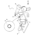
- FIG. 14 illustrates an embodiment of a balancing system for balancing a disk.
- balancing system 1400 includes spindle 1410 for holding disk 1460 in place so that a mass balance may be determined by mass balance machine 1420 .
- Mass balance machine 1420 is able to spin the disk and determine the location of the mass center of the disk. If the disk is not balanced, the mass center of the disk may differ from the rotational center of the disk.
- balancing machine 1420 may include a laser 1440 , a movable stage 1430 , a controller 1440 , and a rotatable spindle 1410 .
- Movable stage 1430 includes optical components to direct a laser beam from a laser source, or a variation thereof, such as a Galvanometer to balance ring 1470 .
- Controller 1440 is connected to movable stage 1430 to control targeting positions of the beam generated by laser 1440 , as discussed below.
- a loading robot 1450 may be part of balancing system 1400 to automatically place disks on spindle 1410 .
- a disk 1460 coupled with balance ring 1470 is loaded onto balancing machine 1420 in front of a movable stage 1430 .
- Balance ring 1470 may be the balance ring discussed in all the previous figures.
- the disk 1460 /balance ring 1470 is secured to spindle 1410 .
- Disk 1460 may be secured in a number of ways including, for examples, through vacuum forces from spindle 1410 or through coupling to the OD of disk 1460 .
- Balancing machine 1420 determines through a control algorithm the mass center of disk 1460 . Balancing machine 1420 instructs spindle 1410 to rotate disk 1460 to a horizontal azimuth with the mass center on the horizontal azimuth. The location and corresponding offset of the mass center from the rotational center, now on the horizontal azimuth, is relayed to controller 1440 . Controller 1440 adjusts stage 1430 to target a laser beam from laser 1440 towards the protuberances on balance ring 1470 . The trimmed protuberances establish a new center of rotation of disk 1460 /balance ring 1470 coincident with its mass center.
- a Galvanometer utilizes a series of x-y mirrors (horizontal-vertical) that are electronically controlled to trim any number of configurations with a laser beam.
- the Galvanometer may include just one mirror that moves the laser beam to a x position relative to the center of the disk, and the balance ring could index each tab to a horizontal alignment. The laser beam could then be reflected in and out to give a specific radius for each of the protuberances.
- a laser is not the only trimming source that may be used.
- other trimming methods may be used.
- a laser source may not be desirable because of the pinpoint focusing nature of lasers.
- vapors resulting from trimming the protuberances may have adverse effects on disk integrity.
- the protuberances may be trimmed using a thermal system.
- a heat source may be used to ablate thermally the protuberances.
- Another alternative source may be ultrasonic energy.
- the protuberances may be mechanically grinded; for example, a diamond burr may be used to trim the protuberances with the debris suctioned off.
- a method to establish a rotational center a disk coincident with its mass center of the disk is described.
- a balance ring is coupled to an ID of a disk.
- Disk balancing protuberances are positioned along an inner diameter of the balance ring.
- the mass center of the disk with the coupled balance ring is then determined and the protuberances are trimmed to align the rotational center of disk/balance ring to be coincident with its mass center.
Abstract
Description
Claims (8)
Priority Applications (1)
| Application Number | Priority Date | Filing Date | Title |
|---|---|---|---|
| US10/850,137 US7099112B1 (en) | 2001-07-25 | 2004-05-19 | Balance ring |
Applications Claiming Priority (3)
| Application Number | Priority Date | Filing Date | Title |
|---|---|---|---|
| US91614401A | 2001-07-25 | 2001-07-25 | |
| US10/712,548 US6778353B1 (en) | 2001-07-25 | 2003-11-12 | Balance ring |
| US10/850,137 US7099112B1 (en) | 2001-07-25 | 2004-05-19 | Balance ring |
Related Parent Applications (1)
| Application Number | Title | Priority Date | Filing Date |
|---|---|---|---|
| US10/712,548 Division US6778353B1 (en) | 2001-07-25 | 2003-11-12 | Balance ring |
Publications (1)
| Publication Number | Publication Date |
|---|---|
| US7099112B1 true US7099112B1 (en) | 2006-08-29 |
Family
ID=36915600
Family Applications (1)
| Application Number | Title | Priority Date | Filing Date |
|---|---|---|---|
| US10/850,137 Expired - Fee Related US7099112B1 (en) | 2001-07-25 | 2004-05-19 | Balance ring |
Country Status (1)
| Country | Link |
|---|---|
| US (1) | US7099112B1 (en) |
Cited By (69)
| Publication number | Priority date | Publication date | Assignee | Title |
|---|---|---|---|---|
| US7916599B1 (en) | 2008-05-23 | 2011-03-29 | Western Digital Technologies, Inc. | Method to balance spindles in a plurality of disk drives |
| US7926167B1 (en) | 2008-08-08 | 2011-04-19 | Western Digital Technologies, Inc. | Method to assemble a disk drive |
| US8828566B2 (en) | 2010-05-21 | 2014-09-09 | Wd Media (Singapore) Pte. Ltd. | Perpendicular magnetic recording disc |
| US8859118B2 (en) | 2010-01-08 | 2014-10-14 | Wd Media (Singapore) Pte. Ltd. | Perpendicular magnetic recording medium |
| US8867322B1 (en) | 2013-05-07 | 2014-10-21 | WD Media, LLC | Systems and methods for providing thermal barrier bilayers for heat assisted magnetic recording media |
| US8877359B2 (en) | 2008-12-05 | 2014-11-04 | Wd Media (Singapore) Pte. Ltd. | Magnetic disk and method for manufacturing same |
| US8908315B2 (en) | 2010-03-29 | 2014-12-09 | Wd Media (Singapore) Pte. Ltd. | Evaluation method of magnetic disk, manufacturing method of magnetic disk, and magnetic disk |
| US8941950B2 (en) | 2012-05-23 | 2015-01-27 | WD Media, LLC | Underlayers for heat assisted magnetic recording (HAMR) media |
| US8947987B1 (en) | 2013-05-03 | 2015-02-03 | WD Media, LLC | Systems and methods for providing capping layers for heat assisted magnetic recording media |
| US8951651B2 (en) | 2010-05-28 | 2015-02-10 | Wd Media (Singapore) Pte. Ltd. | Perpendicular magnetic recording disk |
| US8980076B1 (en) | 2009-05-26 | 2015-03-17 | WD Media, LLC | Electro-deposited passivation coatings for patterned media |
| US8993134B2 (en) | 2012-06-29 | 2015-03-31 | Western Digital Technologies, Inc. | Electrically conductive underlayer to grow FePt granular media with (001) texture on glass substrates |
| US8995078B1 (en) | 2014-09-25 | 2015-03-31 | WD Media, LLC | Method of testing a head for contamination |
| US9001630B1 (en) | 2011-03-08 | 2015-04-07 | Western Digital Technologies, Inc. | Energy assisted magnetic recording medium capable of suppressing high DC readback noise |
| US9005782B2 (en) | 2008-03-30 | 2015-04-14 | WD Media, LLC | Magnetic disk and method of manufacturing the same |
| US9025264B1 (en) | 2011-03-10 | 2015-05-05 | WD Media, LLC | Methods for measuring media performance associated with adjacent track interference |
| US9029308B1 (en) | 2012-03-28 | 2015-05-12 | WD Media, LLC | Low foam media cleaning detergent |
| US9028985B2 (en) | 2011-03-31 | 2015-05-12 | WD Media, LLC | Recording media with multiple exchange coupled magnetic layers |
| US9034492B1 (en) | 2013-01-11 | 2015-05-19 | WD Media, LLC | Systems and methods for controlling damping of magnetic media for heat assisted magnetic recording |
| US9042053B1 (en) | 2014-06-24 | 2015-05-26 | WD Media, LLC | Thermally stabilized perpendicular magnetic recording medium |
| US9047880B1 (en) | 2011-12-20 | 2015-06-02 | WD Media, LLC | Heat assisted magnetic recording method for media having moment keeper layer |
| US9047903B2 (en) | 2008-03-26 | 2015-06-02 | Wd Media (Singapore) Pte. Ltd. | Perpendicular magnetic recording medium and process for manufacture thereof |
| US9064521B1 (en) | 2011-03-25 | 2015-06-23 | WD Media, LLC | Manufacturing of hard masks for patterning magnetic media |
| US9082447B1 (en) | 2014-09-22 | 2015-07-14 | WD Media, LLC | Determining storage media substrate material type |
| US9093100B2 (en) | 2008-03-17 | 2015-07-28 | Wd Media (Singapore) Pte. Ltd. | Magnetic recording medium including tailored exchange coupling layer and manufacturing method of the same |
| US9093122B1 (en) | 2013-04-05 | 2015-07-28 | WD Media, LLC | Systems and methods for improving accuracy of test measurements involving aggressor tracks written to disks of hard disk drives |
| US9142241B2 (en) | 2009-03-30 | 2015-09-22 | Wd Media (Singapore) Pte. Ltd. | Perpendicular magnetic recording medium and method of manufacturing the same |
| US9153268B1 (en) | 2013-02-19 | 2015-10-06 | WD Media, LLC | Lubricants comprising fluorinated graphene nanoribbons for magnetic recording media structure |
| US9159350B1 (en) | 2014-07-02 | 2015-10-13 | WD Media, LLC | High damping cap layer for magnetic recording media |
| US9177586B2 (en) | 2008-09-30 | 2015-11-03 | WD Media (Singapore), LLC | Magnetic disk and manufacturing method thereof |
| US9177585B1 (en) | 2013-10-23 | 2015-11-03 | WD Media, LLC | Magnetic media capable of improving magnetic properties and thermal management for heat-assisted magnetic recording |
| US9183867B1 (en) | 2013-02-21 | 2015-11-10 | WD Media, LLC | Systems and methods for forming implanted capping layers in magnetic media for magnetic recording |
| US9190094B2 (en) | 2013-04-04 | 2015-11-17 | Western Digital (Fremont) | Perpendicular recording media with grain isolation initiation layer and exchange breaking layer for signal-to-noise ratio enhancement |
| US9196283B1 (en) | 2013-03-13 | 2015-11-24 | Western Digital (Fremont), Llc | Method for providing a magnetic recording transducer using a chemical buffer |
| US9218850B1 (en) | 2014-12-23 | 2015-12-22 | WD Media, LLC | Exchange break layer for heat-assisted magnetic recording media |
| US9227324B1 (en) | 2014-09-25 | 2016-01-05 | WD Media, LLC | Mandrel for substrate transport system with notch |
| US9240204B2 (en) | 2010-05-21 | 2016-01-19 | Wd Media (Singapore) Pte. Ltd. | Perpendicular magnetic recording disc |
| US9257134B1 (en) | 2014-12-24 | 2016-02-09 | Western Digital Technologies, Inc. | Allowing fast data zone switches on data storage devices |
| US9269480B1 (en) | 2012-03-30 | 2016-02-23 | WD Media, LLC | Systems and methods for forming magnetic recording media with improved grain columnar growth for energy assisted magnetic recording |
| US9275669B1 (en) | 2015-03-31 | 2016-03-01 | WD Media, LLC | TbFeCo in PMR media for SNR improvement |
| US9280998B1 (en) | 2015-03-30 | 2016-03-08 | WD Media, LLC | Acidic post-sputter wash for magnetic recording media |
| US9296082B1 (en) | 2013-06-11 | 2016-03-29 | WD Media, LLC | Disk buffing apparatus with abrasive tape loading pad having a vibration absorbing layer |
| US9330685B1 (en) | 2009-11-06 | 2016-05-03 | WD Media, LLC | Press system for nano-imprinting of recording media with a two step pressing method |
| US9339978B1 (en) | 2009-11-06 | 2016-05-17 | WD Media, LLC | Press system with interleaved embossing foil holders for nano-imprinting of recording media |
| US9349404B2 (en) | 2010-05-28 | 2016-05-24 | Wd Media (Singapore) Pte. Ltd | Perpendicular magnetic recording disc |
| US9382496B1 (en) | 2013-12-19 | 2016-07-05 | Western Digital Technologies, Inc. | Lubricants with high thermal stability for heat-assisted magnetic recording |
| US9389135B2 (en) | 2013-09-26 | 2016-07-12 | WD Media, LLC | Systems and methods for calibrating a load cell of a disk burnishing machine |
| US9401300B1 (en) | 2014-12-18 | 2016-07-26 | WD Media, LLC | Media substrate gripper including a plurality of snap-fit fingers |
| US9406330B1 (en) | 2013-06-19 | 2016-08-02 | WD Media, LLC | Method for HDD disk defect source detection |
| US9406329B1 (en) | 2015-11-30 | 2016-08-02 | WD Media, LLC | HAMR media structure with intermediate layer underlying a magnetic recording layer having multiple sublayers |
| US9431045B1 (en) | 2014-04-25 | 2016-08-30 | WD Media, LLC | Magnetic seed layer used with an unbalanced soft underlayer |
| US9449633B1 (en) | 2014-11-06 | 2016-09-20 | WD Media, LLC | Smooth structures for heat-assisted magnetic recording media |
| US9447368B1 (en) | 2014-02-18 | 2016-09-20 | WD Media, LLC | Detergent composition with low foam and high nickel solubility |
| US9472227B2 (en) | 2010-06-22 | 2016-10-18 | Wd Media (Singapore) Pte. Ltd. | Perpendicular magnetic recording media and methods for producing the same |
| US9542968B1 (en) | 2010-08-20 | 2017-01-10 | WD Media, LLC | Single layer small grain size FePT:C film for heat assisted magnetic recording media |
| US9558778B2 (en) | 2009-03-28 | 2017-01-31 | Wd Media (Singapore) Pte. Ltd. | Lubricant compound for magnetic disk and magnetic disk |
| US9581510B1 (en) | 2013-12-16 | 2017-02-28 | Western Digital Technologies, Inc. | Sputter chamber pressure gauge with vibration absorber |
| US9607646B2 (en) | 2013-07-30 | 2017-03-28 | WD Media, LLC | Hard disk double lubrication layer |
| US9685184B1 (en) | 2014-09-25 | 2017-06-20 | WD Media, LLC | NiFeX-based seed layer for magnetic recording media |
| US9818442B2 (en) | 2014-12-01 | 2017-11-14 | WD Media, LLC | Magnetic media having improved magnetic grain size distribution and intergranular segregation |
| US9824711B1 (en) | 2014-02-14 | 2017-11-21 | WD Media, LLC | Soft underlayer for heat assisted magnetic recording media |
| US9822441B2 (en) | 2015-03-31 | 2017-11-21 | WD Media, LLC | Iridium underlayer for heat assisted magnetic recording media |
| US9990940B1 (en) | 2014-12-30 | 2018-06-05 | WD Media, LLC | Seed structure for perpendicular magnetic recording media |
| US10054363B2 (en) | 2014-08-15 | 2018-08-21 | WD Media, LLC | Method and apparatus for cryogenic dynamic cooling |
| US10083715B2 (en) | 2010-05-28 | 2018-09-25 | WD Media (Singapore) Pte.Ltd. | Method of manufacturing a perpendicular magnetic disc |
| US10115428B1 (en) | 2013-02-15 | 2018-10-30 | Wd Media, Inc. | HAMR media structure having an anisotropic thermal barrier layer |
| US10121506B1 (en) | 2015-12-29 | 2018-11-06 | WD Media, LLC | Magnetic-recording medium including a carbon overcoat implanted with nitrogen and hydrogen |
| US10236026B1 (en) | 2015-11-06 | 2019-03-19 | WD Media, LLC | Thermal barrier layers and seed layers for control of thermal and structural properties of HAMR media |
| US11074934B1 (en) | 2015-09-25 | 2021-07-27 | Western Digital Technologies, Inc. | Heat assisted magnetic recording (HAMR) media with Curie temperature reduction layer |
Citations (25)
| Publication number | Priority date | Publication date | Assignee | Title |
|---|---|---|---|---|
| JPS60256943A (en) * | 1984-06-01 | 1985-12-18 | Hitachi Ltd | System for correcting unbalance of information carrier disc |
| DE3816975A1 (en) | 1988-05-18 | 1989-11-30 | Siemens Ag | Disk drive of a data storage device |
| JPH02143968A (en) * | 1988-11-24 | 1990-06-01 | Fujitsu Ltd | Spindle hub |
| US5243481A (en) | 1991-09-25 | 1993-09-07 | Integral Peripherals, Inc. | Clamp for information storage disk |
| WO1993026006A1 (en) | 1992-06-08 | 1993-12-23 | Digital Equipment Corporation | Disk centering device |
| JPH0644721A (en) | 1992-07-28 | 1994-02-18 | Nec Corp | Magnetic disk device |
| US5537272A (en) | 1994-05-02 | 1996-07-16 | Seagate Technology, Inc. | Spindle balance device for a hard disk drive assembly |
| JPH09115216A (en) | 1995-10-19 | 1997-05-02 | Hitachi Ltd | Spindle structure of magnetic disk device and magnetic disk device |
| US5659443A (en) | 1995-12-01 | 1997-08-19 | International Business Machines Corporation | Split band retainer for radially clamping a disk to a hub in a disk drive |
| JPH10247359A (en) | 1997-03-05 | 1998-09-14 | Hitachi Ltd | Disk driving device |
| US5834731A (en) | 1997-06-04 | 1998-11-10 | Hmt Technology Corporation | Laser texturing apparatus with bernoulli holder |
| JPH1139786A (en) | 1997-07-22 | 1999-02-12 | Nec Ibaraki Ltd | Device for correcting unbalance of spindle motor and method therefor |
| US5897798A (en) | 1997-06-04 | 1999-04-27 | Hmt Technology Corporation | Laser texturing apparatus employing a rotating mirror |
| JPH11134840A (en) * | 1997-10-28 | 1999-05-21 | Hitachi Ltd | Magnetic disk apparatus and assembling method |
| WO1999058292A1 (en) * | 1998-05-08 | 1999-11-18 | Ucar Carbon Technology Corporation | Tool holder balancing method |
| JPH11326105A (en) * | 1997-12-02 | 1999-11-26 | Guzik Technical Enterp Inc | Method and device for balancing spin stand and disk testing device |
| JPH11353788A (en) * | 1998-06-04 | 1999-12-24 | Hitachi Ltd | Balance correction mechanism for magnetic disk device |
| US6178062B1 (en) | 1998-07-17 | 2001-01-23 | Samsung Electronics Company, Ltd. | Balance tube for a spindle motor assembly of a hard disk drive |
| US6189371B1 (en) | 1995-12-07 | 2001-02-20 | International Business Machines Corporation | Method for adjusting rotation balance of disk and device for the same |
| US6212031B1 (en) | 1997-11-24 | 2001-04-03 | Seagate Technology Llc | Radially-loaded, snap-fit disc mounting system for a disc drive |
| US6226146B1 (en) | 1998-01-08 | 2001-05-01 | Seagate Technology Llc | Multi-point interference disc spacer for a disc drive |
| US20020024762A1 (en) * | 2000-08-23 | 2002-02-28 | Seagate Technology Llc | Disc clamp having adjustable balance ring |
| US6381081B1 (en) | 2001-01-19 | 2002-04-30 | The United States Of America As Represented By The Administrator Of The National Aeronautics And Space Administration | Flexure-ring for centering a concave lens in a bore of a housing for an optical system |
| US20020092351A1 (en) * | 1999-08-20 | 2002-07-18 | Seagate Technology Llc | Dynamic balance correction station for a disc drive |
| US6778353B1 (en) * | 2001-07-25 | 2004-08-17 | Komag, Inc. | Balance ring |
-
2004
- 2004-05-19 US US10/850,137 patent/US7099112B1/en not_active Expired - Fee Related
Patent Citations (27)
| Publication number | Priority date | Publication date | Assignee | Title |
|---|---|---|---|---|
| JPS60256943A (en) * | 1984-06-01 | 1985-12-18 | Hitachi Ltd | System for correcting unbalance of information carrier disc |
| DE3816975A1 (en) | 1988-05-18 | 1989-11-30 | Siemens Ag | Disk drive of a data storage device |
| JPH02143968A (en) * | 1988-11-24 | 1990-06-01 | Fujitsu Ltd | Spindle hub |
| US5243481A (en) | 1991-09-25 | 1993-09-07 | Integral Peripherals, Inc. | Clamp for information storage disk |
| WO1993026006A1 (en) | 1992-06-08 | 1993-12-23 | Digital Equipment Corporation | Disk centering device |
| JPH0644721A (en) | 1992-07-28 | 1994-02-18 | Nec Corp | Magnetic disk device |
| US5537272A (en) | 1994-05-02 | 1996-07-16 | Seagate Technology, Inc. | Spindle balance device for a hard disk drive assembly |
| JPH09115216A (en) | 1995-10-19 | 1997-05-02 | Hitachi Ltd | Spindle structure of magnetic disk device and magnetic disk device |
| US5659443A (en) | 1995-12-01 | 1997-08-19 | International Business Machines Corporation | Split band retainer for radially clamping a disk to a hub in a disk drive |
| US6189371B1 (en) | 1995-12-07 | 2001-02-20 | International Business Machines Corporation | Method for adjusting rotation balance of disk and device for the same |
| JPH10247359A (en) | 1997-03-05 | 1998-09-14 | Hitachi Ltd | Disk driving device |
| US5897798A (en) | 1997-06-04 | 1999-04-27 | Hmt Technology Corporation | Laser texturing apparatus employing a rotating mirror |
| US5834731A (en) | 1997-06-04 | 1998-11-10 | Hmt Technology Corporation | Laser texturing apparatus with bernoulli holder |
| JPH1139786A (en) | 1997-07-22 | 1999-02-12 | Nec Ibaraki Ltd | Device for correcting unbalance of spindle motor and method therefor |
| JPH11134840A (en) * | 1997-10-28 | 1999-05-21 | Hitachi Ltd | Magnetic disk apparatus and assembling method |
| US6212031B1 (en) | 1997-11-24 | 2001-04-03 | Seagate Technology Llc | Radially-loaded, snap-fit disc mounting system for a disc drive |
| JPH11326105A (en) * | 1997-12-02 | 1999-11-26 | Guzik Technical Enterp Inc | Method and device for balancing spin stand and disk testing device |
| US6226146B1 (en) | 1998-01-08 | 2001-05-01 | Seagate Technology Llc | Multi-point interference disc spacer for a disc drive |
| WO1999058292A1 (en) * | 1998-05-08 | 1999-11-18 | Ucar Carbon Technology Corporation | Tool holder balancing method |
| JPH11353788A (en) * | 1998-06-04 | 1999-12-24 | Hitachi Ltd | Balance correction mechanism for magnetic disk device |
| US6178062B1 (en) | 1998-07-17 | 2001-01-23 | Samsung Electronics Company, Ltd. | Balance tube for a spindle motor assembly of a hard disk drive |
| US20020092351A1 (en) * | 1999-08-20 | 2002-07-18 | Seagate Technology Llc | Dynamic balance correction station for a disc drive |
| US6550328B1 (en) * | 1999-08-20 | 2003-04-22 | Jpmorgan Chase Bank | Dynamic balance correction for a disc drive |
| US20020024762A1 (en) * | 2000-08-23 | 2002-02-28 | Seagate Technology Llc | Disc clamp having adjustable balance ring |
| US20030193738A1 (en) * | 2000-08-23 | 2003-10-16 | Renken Frederick Paul | Retainer for an adjustable balance ring in a disc clamp assembly |
| US6381081B1 (en) | 2001-01-19 | 2002-04-30 | The United States Of America As Represented By The Administrator Of The National Aeronautics And Space Administration | Flexure-ring for centering a concave lens in a bore of a housing for an optical system |
| US6778353B1 (en) * | 2001-07-25 | 2004-08-17 | Komag, Inc. | Balance ring |
Non-Patent Citations (2)
| Title |
|---|
| "Contamination-Free Balancing of Spindle/Hub Motors," Oct. 1, 1989, IBM Technical Disclosure Bulletin, vol. No. 32, Iss. No. 5B, pp. 333-334. * |
| "Flexure Rings for Centering Lenses", NASA Tech Brief, vol. 26, No. 11 from JPL New Technology Report NO-19518, Nov. 1, 2002, pp. i, 1-6. |
Cited By (71)
| Publication number | Priority date | Publication date | Assignee | Title |
|---|---|---|---|---|
| US9093100B2 (en) | 2008-03-17 | 2015-07-28 | Wd Media (Singapore) Pte. Ltd. | Magnetic recording medium including tailored exchange coupling layer and manufacturing method of the same |
| US9047903B2 (en) | 2008-03-26 | 2015-06-02 | Wd Media (Singapore) Pte. Ltd. | Perpendicular magnetic recording medium and process for manufacture thereof |
| US9005782B2 (en) | 2008-03-30 | 2015-04-14 | WD Media, LLC | Magnetic disk and method of manufacturing the same |
| US7916599B1 (en) | 2008-05-23 | 2011-03-29 | Western Digital Technologies, Inc. | Method to balance spindles in a plurality of disk drives |
| US7926167B1 (en) | 2008-08-08 | 2011-04-19 | Western Digital Technologies, Inc. | Method to assemble a disk drive |
| US9984715B2 (en) | 2008-09-30 | 2018-05-29 | WD Media, LLC | Magnetic disk and manufacturing method thereof |
| US9177586B2 (en) | 2008-09-30 | 2015-11-03 | WD Media (Singapore), LLC | Magnetic disk and manufacturing method thereof |
| US8877359B2 (en) | 2008-12-05 | 2014-11-04 | Wd Media (Singapore) Pte. Ltd. | Magnetic disk and method for manufacturing same |
| US9558778B2 (en) | 2009-03-28 | 2017-01-31 | Wd Media (Singapore) Pte. Ltd. | Lubricant compound for magnetic disk and magnetic disk |
| US9142241B2 (en) | 2009-03-30 | 2015-09-22 | Wd Media (Singapore) Pte. Ltd. | Perpendicular magnetic recording medium and method of manufacturing the same |
| US8980076B1 (en) | 2009-05-26 | 2015-03-17 | WD Media, LLC | Electro-deposited passivation coatings for patterned media |
| US9339978B1 (en) | 2009-11-06 | 2016-05-17 | WD Media, LLC | Press system with interleaved embossing foil holders for nano-imprinting of recording media |
| US9330685B1 (en) | 2009-11-06 | 2016-05-03 | WD Media, LLC | Press system for nano-imprinting of recording media with a two step pressing method |
| US8859118B2 (en) | 2010-01-08 | 2014-10-14 | Wd Media (Singapore) Pte. Ltd. | Perpendicular magnetic recording medium |
| US8908315B2 (en) | 2010-03-29 | 2014-12-09 | Wd Media (Singapore) Pte. Ltd. | Evaluation method of magnetic disk, manufacturing method of magnetic disk, and magnetic disk |
| US9240204B2 (en) | 2010-05-21 | 2016-01-19 | Wd Media (Singapore) Pte. Ltd. | Perpendicular magnetic recording disc |
| US8828566B2 (en) | 2010-05-21 | 2014-09-09 | Wd Media (Singapore) Pte. Ltd. | Perpendicular magnetic recording disc |
| US10083715B2 (en) | 2010-05-28 | 2018-09-25 | WD Media (Singapore) Pte.Ltd. | Method of manufacturing a perpendicular magnetic disc |
| US8951651B2 (en) | 2010-05-28 | 2015-02-10 | Wd Media (Singapore) Pte. Ltd. | Perpendicular magnetic recording disk |
| US9349404B2 (en) | 2010-05-28 | 2016-05-24 | Wd Media (Singapore) Pte. Ltd | Perpendicular magnetic recording disc |
| US9472227B2 (en) | 2010-06-22 | 2016-10-18 | Wd Media (Singapore) Pte. Ltd. | Perpendicular magnetic recording media and methods for producing the same |
| US9542968B1 (en) | 2010-08-20 | 2017-01-10 | WD Media, LLC | Single layer small grain size FePT:C film for heat assisted magnetic recording media |
| US9001630B1 (en) | 2011-03-08 | 2015-04-07 | Western Digital Technologies, Inc. | Energy assisted magnetic recording medium capable of suppressing high DC readback noise |
| US9025264B1 (en) | 2011-03-10 | 2015-05-05 | WD Media, LLC | Methods for measuring media performance associated with adjacent track interference |
| US9064521B1 (en) | 2011-03-25 | 2015-06-23 | WD Media, LLC | Manufacturing of hard masks for patterning magnetic media |
| US9028985B2 (en) | 2011-03-31 | 2015-05-12 | WD Media, LLC | Recording media with multiple exchange coupled magnetic layers |
| US9047880B1 (en) | 2011-12-20 | 2015-06-02 | WD Media, LLC | Heat assisted magnetic recording method for media having moment keeper layer |
| US9029308B1 (en) | 2012-03-28 | 2015-05-12 | WD Media, LLC | Low foam media cleaning detergent |
| US9269480B1 (en) | 2012-03-30 | 2016-02-23 | WD Media, LLC | Systems and methods for forming magnetic recording media with improved grain columnar growth for energy assisted magnetic recording |
| US8941950B2 (en) | 2012-05-23 | 2015-01-27 | WD Media, LLC | Underlayers for heat assisted magnetic recording (HAMR) media |
| US8993134B2 (en) | 2012-06-29 | 2015-03-31 | Western Digital Technologies, Inc. | Electrically conductive underlayer to grow FePt granular media with (001) texture on glass substrates |
| US9034492B1 (en) | 2013-01-11 | 2015-05-19 | WD Media, LLC | Systems and methods for controlling damping of magnetic media for heat assisted magnetic recording |
| US10115428B1 (en) | 2013-02-15 | 2018-10-30 | Wd Media, Inc. | HAMR media structure having an anisotropic thermal barrier layer |
| US9153268B1 (en) | 2013-02-19 | 2015-10-06 | WD Media, LLC | Lubricants comprising fluorinated graphene nanoribbons for magnetic recording media structure |
| US9183867B1 (en) | 2013-02-21 | 2015-11-10 | WD Media, LLC | Systems and methods for forming implanted capping layers in magnetic media for magnetic recording |
| US9196283B1 (en) | 2013-03-13 | 2015-11-24 | Western Digital (Fremont), Llc | Method for providing a magnetic recording transducer using a chemical buffer |
| US9190094B2 (en) | 2013-04-04 | 2015-11-17 | Western Digital (Fremont) | Perpendicular recording media with grain isolation initiation layer and exchange breaking layer for signal-to-noise ratio enhancement |
| US9093122B1 (en) | 2013-04-05 | 2015-07-28 | WD Media, LLC | Systems and methods for improving accuracy of test measurements involving aggressor tracks written to disks of hard disk drives |
| US8947987B1 (en) | 2013-05-03 | 2015-02-03 | WD Media, LLC | Systems and methods for providing capping layers for heat assisted magnetic recording media |
| US8867322B1 (en) | 2013-05-07 | 2014-10-21 | WD Media, LLC | Systems and methods for providing thermal barrier bilayers for heat assisted magnetic recording media |
| US9296082B1 (en) | 2013-06-11 | 2016-03-29 | WD Media, LLC | Disk buffing apparatus with abrasive tape loading pad having a vibration absorbing layer |
| US9406330B1 (en) | 2013-06-19 | 2016-08-02 | WD Media, LLC | Method for HDD disk defect source detection |
| US9607646B2 (en) | 2013-07-30 | 2017-03-28 | WD Media, LLC | Hard disk double lubrication layer |
| US9389135B2 (en) | 2013-09-26 | 2016-07-12 | WD Media, LLC | Systems and methods for calibrating a load cell of a disk burnishing machine |
| US9177585B1 (en) | 2013-10-23 | 2015-11-03 | WD Media, LLC | Magnetic media capable of improving magnetic properties and thermal management for heat-assisted magnetic recording |
| US9581510B1 (en) | 2013-12-16 | 2017-02-28 | Western Digital Technologies, Inc. | Sputter chamber pressure gauge with vibration absorber |
| US9382496B1 (en) | 2013-12-19 | 2016-07-05 | Western Digital Technologies, Inc. | Lubricants with high thermal stability for heat-assisted magnetic recording |
| US9824711B1 (en) | 2014-02-14 | 2017-11-21 | WD Media, LLC | Soft underlayer for heat assisted magnetic recording media |
| US9447368B1 (en) | 2014-02-18 | 2016-09-20 | WD Media, LLC | Detergent composition with low foam and high nickel solubility |
| US9431045B1 (en) | 2014-04-25 | 2016-08-30 | WD Media, LLC | Magnetic seed layer used with an unbalanced soft underlayer |
| US9042053B1 (en) | 2014-06-24 | 2015-05-26 | WD Media, LLC | Thermally stabilized perpendicular magnetic recording medium |
| US9159350B1 (en) | 2014-07-02 | 2015-10-13 | WD Media, LLC | High damping cap layer for magnetic recording media |
| US10054363B2 (en) | 2014-08-15 | 2018-08-21 | WD Media, LLC | Method and apparatus for cryogenic dynamic cooling |
| US9082447B1 (en) | 2014-09-22 | 2015-07-14 | WD Media, LLC | Determining storage media substrate material type |
| US9227324B1 (en) | 2014-09-25 | 2016-01-05 | WD Media, LLC | Mandrel for substrate transport system with notch |
| US9685184B1 (en) | 2014-09-25 | 2017-06-20 | WD Media, LLC | NiFeX-based seed layer for magnetic recording media |
| US8995078B1 (en) | 2014-09-25 | 2015-03-31 | WD Media, LLC | Method of testing a head for contamination |
| US9449633B1 (en) | 2014-11-06 | 2016-09-20 | WD Media, LLC | Smooth structures for heat-assisted magnetic recording media |
| US10783915B2 (en) | 2014-12-01 | 2020-09-22 | Western Digital Technologies, Inc. | Magnetic media having improved magnetic grain size distribution and intergranular segregation |
| US9818442B2 (en) | 2014-12-01 | 2017-11-14 | WD Media, LLC | Magnetic media having improved magnetic grain size distribution and intergranular segregation |
| US9401300B1 (en) | 2014-12-18 | 2016-07-26 | WD Media, LLC | Media substrate gripper including a plurality of snap-fit fingers |
| US9218850B1 (en) | 2014-12-23 | 2015-12-22 | WD Media, LLC | Exchange break layer for heat-assisted magnetic recording media |
| US9257134B1 (en) | 2014-12-24 | 2016-02-09 | Western Digital Technologies, Inc. | Allowing fast data zone switches on data storage devices |
| US9990940B1 (en) | 2014-12-30 | 2018-06-05 | WD Media, LLC | Seed structure for perpendicular magnetic recording media |
| US9280998B1 (en) | 2015-03-30 | 2016-03-08 | WD Media, LLC | Acidic post-sputter wash for magnetic recording media |
| US9822441B2 (en) | 2015-03-31 | 2017-11-21 | WD Media, LLC | Iridium underlayer for heat assisted magnetic recording media |
| US9275669B1 (en) | 2015-03-31 | 2016-03-01 | WD Media, LLC | TbFeCo in PMR media for SNR improvement |
| US11074934B1 (en) | 2015-09-25 | 2021-07-27 | Western Digital Technologies, Inc. | Heat assisted magnetic recording (HAMR) media with Curie temperature reduction layer |
| US10236026B1 (en) | 2015-11-06 | 2019-03-19 | WD Media, LLC | Thermal barrier layers and seed layers for control of thermal and structural properties of HAMR media |
| US9406329B1 (en) | 2015-11-30 | 2016-08-02 | WD Media, LLC | HAMR media structure with intermediate layer underlying a magnetic recording layer having multiple sublayers |
| US10121506B1 (en) | 2015-12-29 | 2018-11-06 | WD Media, LLC | Magnetic-recording medium including a carbon overcoat implanted with nitrogen and hydrogen |
Similar Documents
| Publication | Publication Date | Title |
|---|---|---|
| US7099112B1 (en) | Balance ring | |
| US6778353B1 (en) | Balance ring | |
| KR100528112B1 (en) | Apparatus and method for manufacturing disc-shaped recording medium | |
| JPH10249264A (en) | Method and apparatus for forming protective coat | |
| US6181669B1 (en) | Apparatus for adjusting a tilt of a disc loaded on a turn table | |
| US6504673B2 (en) | Asymmetrical disc clamp | |
| US6061205A (en) | Slider support assembly and method | |
| US6285651B1 (en) | Optical disc for optical storage system | |
| US6353590B1 (en) | Media stabilization for laser servowriting | |
| US6205002B1 (en) | Disk drive with textured slider contact region | |
| JPS61150162A (en) | Support mechanism of optical disc driver | |
| JP2981333B2 (en) | Optical information recording medium | |
| JPH10199056A (en) | Protective film forming device and protective film forming method | |
| JPH03178077A (en) | Drive device for optical disk | |
| JPH11259967A (en) | Disk rotation drive device and its manufacture | |
| JPH10302251A (en) | Disc-type magnetic recording medium and magnetic recording/reproducing device | |
| EP1561576B1 (en) | Correcting stage, apparatus and method for laminating and laminated recording medium | |
| JPH07282453A (en) | Optical disk driving device | |
| JP4035318B2 (en) | Optical disk device | |
| JPH01223643A (en) | Recording medium for optical disk | |
| JPS60145538A (en) | Optical recording and reproducing method and its device | |
| JP2002358759A (en) | Information recording and reproducing device and rough regulation method for information recording and reproducing device | |
| JPH01320434A (en) | Optical encoder | |
| JPH0244543A (en) | Optical information recording disk | |
| JPH11134788A (en) | Turntable |
Legal Events
| Date | Code | Title | Description |
|---|---|---|---|
| AS | Assignment |
Owner name: WD MEDIA, INC., CALIFORNIA Free format text: MERGER;ASSIGNOR:KOMAG, INC.;REEL/FRAME:021172/0562 Effective date: 20070905 |
|
| AS | Assignment |
Owner name: KOMAG, INC., CALIFORNIA Free format text: ASSIGNMENT OF ASSIGNORS INTEREST;ASSIGNOR:HARPER, BRUCE M.;REEL/FRAME:021194/0979 Effective date: 20010724 |
|
| FPAY | Fee payment |
Year of fee payment: 4 |
|
| FPAY | Fee payment |
Year of fee payment: 8 |
|
| AS | Assignment |
Owner name: JPMORGAN CHASE BANK, N.A., AS COLLATERAL AGENT, ILLINOIS Free format text: SECURITY AGREEMENT;ASSIGNOR:WD MEDIA, LLC;REEL/FRAME:038709/0879 Effective date: 20160512 Owner name: U.S. BANK NATIONAL ASSOCIATION, AS COLLATERAL AGENT, CALIFORNIA Free format text: SECURITY AGREEMENT;ASSIGNOR:WD MEDIA, LLC;REEL/FRAME:038709/0931 Effective date: 20160512 Owner name: JPMORGAN CHASE BANK, N.A., AS COLLATERAL AGENT, ILLINOIS Free format text: SECURITY AGREEMENT;ASSIGNOR:WD MEDIA, LLC;REEL/FRAME:038710/0383 Effective date: 20160512 Owner name: U.S. BANK NATIONAL ASSOCIATION, AS COLLATERAL AGEN Free format text: SECURITY AGREEMENT;ASSIGNOR:WD MEDIA, LLC;REEL/FRAME:038709/0931 Effective date: 20160512 Owner name: JPMORGAN CHASE BANK, N.A., AS COLLATERAL AGENT, IL Free format text: SECURITY AGREEMENT;ASSIGNOR:WD MEDIA, LLC;REEL/FRAME:038709/0879 Effective date: 20160512 Owner name: JPMORGAN CHASE BANK, N.A., AS COLLATERAL AGENT, IL Free format text: SECURITY AGREEMENT;ASSIGNOR:WD MEDIA, LLC;REEL/FRAME:038710/0383 Effective date: 20160512 |
|
| AS | Assignment |
Owner name: WD MEDIA, LLC, CALIFORNIA Free format text: RELEASE BY SECURED PARTY;ASSIGNOR:U.S. BANK NATIONAL ASSOCIATION, AS COLLATERAL AGENT;REEL/FRAME:045501/0672 Effective date: 20180227 |
|
| FEPP | Fee payment procedure |
Free format text: MAINTENANCE FEE REMINDER MAILED (ORIGINAL EVENT CODE: REM.) |
|
| LAPS | Lapse for failure to pay maintenance fees |
Free format text: PATENT EXPIRED FOR FAILURE TO PAY MAINTENANCE FEES (ORIGINAL EVENT CODE: EXP.); ENTITY STATUS OF PATENT OWNER: LARGE ENTITY |
|
| STCH | Information on status: patent discontinuation |
Free format text: PATENT EXPIRED DUE TO NONPAYMENT OF MAINTENANCE FEES UNDER 37 CFR 1.362 |
|
| FP | Lapsed due to failure to pay maintenance fee |
Effective date: 20180829 |
|
| AS | Assignment |
Owner name: WESTERN DIGITAL TECHNOLOGIES, INC., CALIFORNIA Free format text: RELEASE OF SECURITY INTEREST AT REEL 038710 FRAME 0383;ASSIGNOR:JPMORGAN CHASE BANK, N.A.;REEL/FRAME:058965/0410 Effective date: 20220203 Owner name: WD MEDIA, LLC, CALIFORNIA Free format text: RELEASE OF SECURITY INTEREST AT REEL 038710 FRAME 0383;ASSIGNOR:JPMORGAN CHASE BANK, N.A.;REEL/FRAME:058965/0410 Effective date: 20220203 |