US7086366B1 - Energy efficient fluid pump - Google Patents
Energy efficient fluid pump Download PDFInfo
- Publication number
- US7086366B1 US7086366B1 US09/489,525 US48952500A US7086366B1 US 7086366 B1 US7086366 B1 US 7086366B1 US 48952500 A US48952500 A US 48952500A US 7086366 B1 US7086366 B1 US 7086366B1
- Authority
- US
- United States
- Prior art keywords
- fluid
- pump element
- secondary pump
- discharge port
- leak back
- Prior art date
- Legal status (The legal status is an assumption and is not a legal conclusion. Google has not performed a legal analysis and makes no representation as to the accuracy of the status listed.)
- Expired - Lifetime
Links
Images


Classifications
-
- F—MECHANICAL ENGINEERING; LIGHTING; HEATING; WEAPONS; BLASTING
- F01—MACHINES OR ENGINES IN GENERAL; ENGINE PLANTS IN GENERAL; STEAM ENGINES
- F01M—LUBRICATING OF MACHINES OR ENGINES IN GENERAL; LUBRICATING INTERNAL COMBUSTION ENGINES; CRANKCASE VENTILATING
- F01M1/00—Pressure lubrication
- F01M1/02—Pressure lubrication using lubricating pumps
- F01M2001/0253—Pressure lubrication using lubricating pumps characterised by the pump driving means
- F01M2001/0276—Pressure lubrication using lubricating pumps characterised by the pump driving means driven by a balancer shaft
-
- F—MECHANICAL ENGINEERING; LIGHTING; HEATING; WEAPONS; BLASTING
- F01—MACHINES OR ENGINES IN GENERAL; ENGINE PLANTS IN GENERAL; STEAM ENGINES
- F01M—LUBRICATING OF MACHINES OR ENGINES IN GENERAL; LUBRICATING INTERNAL COMBUSTION ENGINES; CRANKCASE VENTILATING
- F01M1/00—Pressure lubrication
- F01M1/12—Closed-circuit lubricating systems not provided for in groups F01M1/02 - F01M1/10
- F01M2001/123—Closed-circuit lubricating systems not provided for in groups F01M1/02 - F01M1/10 using two or more pumps
Definitions
- the present invention relates to a fluid pump system for an engine or other system. More specifically, the present invention relates to a dual pumping element system which allows for the reduction of driving power consumption by effectively switching one pump element out of the system when the engine is operating above a pre-determined fluid pressure.
- Fluid pump systems and specifically oil pump systems, are well known in the art.
- the oil pump is driven by an engine s crankshaft and is either located on the front of the engine or in the oil pan. Because the oil pump is driven by the crankshaft, it runs at a fixed speed ratio to the engine crankshaft, which ratio is determined by the flow volume required to maintain oil pressure at low speeds. This ratio produces excessive flow volume, however, which may result in significant energy loss, at higher engine speeds. Moreover, if the oil pump is located on the front of the engine, enough space must be provided to accommodate it.
- dual engine balance shafts for certain engines are known in the art to aid in balancing engine vibration and in reducing engine noise. Examples of the use of dual engine balance shafts are disclosed in U.S. Pat. No. 4,703,724 assigned to Chrysler Motors Corporation and U.S. Pat. No. 5,535,643 assigned to General Motors Corporation.
- the balance shafts are connected to the engine crankshaft in such a way as to rotate at twice the crankshaft speed.
- the two balance shafts also rotate in opposite directions to cancel each other's lateral unbalance.
- the balance shafts counterbalance the vertical shaking forces caused by the acceleration and deceleration of the reciprocating piston assemblies and connection rods.
- balance shafts One problem with the use of balance shafts is that the firing and compression strokes alternately accelerate and decelerate the crankshaft s rotation. These angular accelerations of the crankshaft occur at all engine speeds. However, the “Rigid Body Motion” angular displacements which result are greatest at low speeds, where the capacity for kinetic energy storage (a function of the square of velocity) by the engine s rotating inertia is low, and the time duration of the acceleration phases are high.
- This Rigid Body Motion which is greatest at low speed engine operation can create gear rattle by alternately speeding up and slowing down the input shaft of the two counter-rotating balance shafts.
- the meshing clearance or backlash between the teeth of the two gears opens and then closes noisily, while the balance shafts attempt to maintain constant rotational speed by virtue of their inertia.
- An illustrative dual pumping system includes an engine having a pair of engine balance shafts.
- the engine balance shaft is drivingly connected to a primary positive displacement pump which operates whenever the engine is running.
- the secondary positive displacement pump is connected to a second engine balance shaft.
- the secondary positive displacement pump supplies its full output flow to the engine only at low engine speeds.
- the primary positive displacement pump and the secondary positive displacement pump are interconnected by a fluid control valve that operates to divert the fluid flow from the secondary positive displacement pump away from the engine when the oil pressure in the engine reaches a predetermined level.
- a small supply of fluid is passed from the outlet of the primary positive displacement pump to the inlet of the secondary positive displacement pump through a flow-restricted cross-over port, or by means of controlled backflow from the secondary pump's discharge passageway.
- a relief valve is available in the output line of the primary positive displacement pump connected to the engine that allows excess volume to return to the sump while maintaining pressure.
- FIG. 1 is a perspective view of an energy efficient oil pump system in accordance with a preferred embodiment of the present invention
- FIG. 2 is a schematic illustration of a fluid control valve in an initial position and a flow circuit in accordance with the present invention when the pressure is below the threshold pressure;
- FIG. 3 is schematic illustration of a flow circuit for a preferred embodiment of the fluid control valve in a second position, when the pressure has just reached the threshold pressure;
- FIG. 4 is a schematic illustration of a flow circuit for a preferred embodiment of the fluid control valve in a third position where the fluid control valve has started to close off both the oil input to the secondary positive displacement pump and the oil output to the engine from the secondary positive displacement pump, while partially opening the recirculation passageway of the secondary pump;
- FIG. 5 is a schematic illustration of a flow circuit for a preferred embodiment of the fluid control valve in a fourth position with the input of oil to the secondary positive displacement pump and output of oil to the engine from the secondary positive displacement pump completely shut-off, while the recirculation passageway of the secondary pump is substantially fully open and the relief valve is about to open;
- FIG. 6 is a schematic illustration of a flow circuit for a preferred embodiment of the fluid control valve with the valve in a fifth position with the relief valve for the primary positive displacement pump in the open position;
- FIG. 7 is a schematic illustration of a flow circuit for an alternative preferred embodiment utilizing an electronically controlled fluid control valve in accordance with the present invention.
- FIG. 8 is a graph charting the volume of fluid pumped versus engine speed for a prior art pump and an energy efficient pump system in accordance with the present invention
- FIG. 9 is a schematic illustration of a flow circuit for an alternative preferred embodiment of a fluid control valve with the valve in a fifth position with the relief valve for the primary positive displacement pump in the open position;
- FIG. 10 is a schematic illustration of a portion of a fluid control valve having a plunger portion with a radial groove in accordance with a preferred embodiment of the present invention.
- FIG. 11 is a schematic illustration of a portion of a fluid control valve having bleeder notches formed in the valve body in accordance with a preferred embodiment of the present invention.
- FIG. 12 is a schematic illustration of a portion of a fluid control valve having a notched plunger portion in accordance with a preferred embodiment of the present invention.
- FIG. 13 is a schematic illustration of a portion of a fluid control valve having a bore formed through a plunger portion in accordance with a preferred embodiment of the present invention.
- FIG. 14 is a schematic illustration of a portion of a fluid control valve in a not fully closed position to allow leakback in accordance with a preferred embodiment of the present invention.
- FIGS. 1 through 6 a preferred embodiment of an oil pump system 10 , in accordance with the present invention, is disclosed.
- the present invention is not limited to an oil pump system and may be utilized in any fluid pumping system with a variety of other fluids.
- the following description of an oil pump system is merely illustrative will be understood as such by one of skill in the art.
- the type of oil pump used with the present invention is preferably a positive displacement oil pump.
- Pumps of this type include internal tip-sealing rotors, hereafter referred to as “geroter” pumps, vane pumps, gear pumps, and piston pumps.
- geroter internal tip-sealing rotors
- vane pumps vane pumps
- gear pumps gear pumps
- piston pumps piston pumps
- geroter-type pump will be utilized which also constitutes the preferred form of the invention.
- any pump can be utilized and that the depiction of a geroter pump is simply illustrative. Hereinafter, this element will be referred to simply by the term “pump”.
- the oil pump system 10 is part of a vehicle engine (not shown).
- the oil pump system 10 includes a balance shaft system preferably located in the oil sump below the engine.
- the balance shaft system includes a pair of twin counter-rotating balance shafts 12 and 14 which help counteract the secondary shaking forces of an inline four cylinder internal combustion piston engine.
- the pair of twin counter-rotating balance shafts comprises a primary balance shaft 12 and a secondary balance shaft 14 .
- the primary balance shaft 12 is the driving shaft, while the secondary balance shaft 14 is the slave or driven balance shaft.
- the primary balance shaft 12 has an input end 16 and an output end 18 . It will be understood that the orientation of the ends 16 , 18 in the figures is merely for purposes of illustration. The input ends 16 , 18 can be reversed or differently configured in accordance with the present invention.
- the input end 16 of the primary balance shaft 12 is connected to and driven by the engine crankshaft 20 through a sprocket or gear 22 and a speed-increasing gear set 27 , 29 .
- the primary balance shaft 12 has at least one gear 28 of a shaft coupling gear set 30 mounted at the output end 18 of the primary balance shaft 12 . By this arrangement, the crankshaft 20 drives the primary shaft 12 at a 2:1 relationship.
- the secondary shaft 14 also has an input end 32 and an output end 34 .
- the input end 32 of the secondary shaft 14 has another gear 36 , of the shaft coupling gear set 30 , mounted thereon.
- the output end 18 of the primary shaft 12 thus communicates with the input end 32 of the secondary shaft 14 through the shaft coupling gear set 30 with gear 28 being in a meshing relationship with gear 36 so that the primary shaft 12 drives the secondary shaft 14 .
- the shaft coupling gear set 30 maintains an angular relationship between the primary shaft 12 and the secondary shaft 14 .
- the shaft coupling gear set 30 including gears 28 and 36 , are shown illustratively as located at one end of the shafts 12 and 14 .
- the shaft coupling gear set 30 can obviously be located anywhere along the length of the primary shaft 12 and secondary shaft 14 .
- the primary shaft 12 is in communication with a primary pump 24 .
- the primary pump 24 is preferably mounted on an intermediate shaft 25 .
- the intermediate shaft 25 has a gear 27 mounted thereon which communicates with a gear 29 mounted on the primary balance shaft 12 . This arrangement reduces the speed for cavitation avoidance of the primary pump 24 and reduces system noise.
- the primary pump 24 can be located in a variety of other locations in the system, including on the primary shaft 12 , on the crankshaft, or on the secondary shaft 14 . Mounting of the primary pump 24 on the intermediate shaft 25 is merely illustrative.
- the secondary shaft 14 has a secondary pump 38 mounted thereon.
- the oil pumps described herein are preferably gerotor oil pumps which are well known in the art. However, it is within the spirit and scope of the present invention that any commercially available oil pumps may be utilized.
- Each of the pumps 24 and 38 comprises an outer ring 40 and a rotor 42 .
- the outer ring 40 has a generally circular outer periphery 44 , a hollow center area 46 , and an inner periphery 48 with a plurality of pockets 50 formed therein.
- the rotor 42 is positioned in the hollow center area 46 of the outer ring 40 and has a plurality of teeth 52 that mate with the pockets 50 as the pumps 24 , 38 operate.
- the primary pump 24 operates to pump oil to the engine at all times when the engine is running.
- the secondary pump 38 operates for this purpose only when the oil pressure is below a predetermined target which generally occurs at lower engine speeds.
- both the primary pump 24 and the secondary pump 38 work in parallel and feed into the same supply outlet to supply the requisite oil flow for the engine.
- one of the two pumps becomes progressively disabled from further contribution to the output oil flow volume.
- the secondary pump 38 is disabled from pumping oil to the engine by recirculating its output back to its inlet, which minimizes power consumption by minimizing the pressure differential across the pump.
- the switching function of the secondary pump 38 is performed by a pressure regulated fluid control valve mechanism 54 which is activated solely by engine oil pressure. This arrangement minimizes the complexity and cost of the fluid control system, and reduces the associated power consumption.
- the primary pump 24 and the secondary pump 38 are interconnected by the fluid control valve mechanism 54 to switch the secondary pump 38 out of the system at a predetermined pressure.
- the primary pump 24 has an inlet opening 56 and an outlet opening 58 to pump oil from an oil pan or sump 60 to the engine 61 .
- the secondary pump has an inlet opening 62 and an outlet opening 64 to pump oil from the oil pan 60 to the engine.
- the oil pan 60 accumulates the engine oil for recirculation.
- a primary oil pickup 66 is located in the oil pan 60 and is in fluid communication with a primary pump inlet passageway 68 to transfer oil from the oil pan 60 to the inlet opening 56 of the primary pump 24 .
- a secondary oil pickup 69 is also in fluid communication with a secondary pump inlet passageway 70 to transfer oil from the oil pan 60 to the secondary pump inlet opening 62 of the secondary pump 38 , as required.
- the outlet opening 58 of the primary pump 24 is in fluid communication with the engine 61 via a primary outlet passageway 72 .
- the outlet opening 58 of the primary pump 24 is also in fluid communication with the fluid control valve mechanism 54 by a valve inlet passage 74 .
- outlet opening 64 of the secondary pump 38 is in fluid communication with the engine via a secondary outlet passageway 76 .
- only one oil pickup is included which splits into two separate passages with one branch feeding the primary pump inlet opening 56 the other branch feeding and the secondary pump inlet opening 62 .
- the fluid control valve mechanism 54 comprises a movable valve or piston member 78 which is sealingly positioned in a valve housing 80 .
- the movable valve member 78 is preferably moveable from an open position, shown in FIG. 2 to a closed position, shown in FIG. 6 .
- the valve mechanism 54 further includes a biasing spring 82 which biases the moveable valve member 78 into the open position.
- the movable valve member 78 is preferably a three-chambered spool valve and comprising a first end 84 that is in communication with the fluid control valve inlet passage 74 , a first plunger portion 86 , a second plunger portion 87 , and a second end 88 that is in communication with the biasing spring 82 .
- the biasing spring 82 is attached within the valve housing 80 at a fixed spring attachment point 90 and exerts force on the second end 88 of the movable valve member 78 .
- the arrangement of the valve member 78 is that of a “spool valve”, which allows the pressure of the secondary pump to act equally on the opposing internal faces of the plunger portions that define the fluid passageway. This avoids unwanted biasing of the valve plungers to provide for consistency of valve response to engine oil pressure.
- Alternative valve member arrangements may be employed.
- the movable valve member is also preferably a three function valve.
- both the primary pump 24 and the secondary pump 38 receive oil from the oil sump 60 through passageways 68 and 70 , respectively. Both the primary pump 24 and the secondary pump 38 draw oil into their respective input openings 56 and 62 and discharge oil from their respective outlet openings 58 and 64 through respective passageways 72 and 76 to the engine 61 .
- the pumps operate at lower speeds and thus, the pressure in the engine is below the pressure threshold necessary to cause the movable valve member 78 to shift.
- FIG. 3 schematically illustrates the oil pump system 10 in accordance with the present invention when the pressure in the engine has reached a predetermined pressure threshold level.
- the movable valve member 78 has shifted away from its initial position ( FIG. 2 ) towards its fifth position ( FIG. 6 ) at the end of its range of travel.
- the oil pressure from the engine has reached a level that the oil pressure present in passage 74 acting on the first end 84 of the movable valve member 78 causes the movable valve member 78 to begin to overcome the biasing force of the spring 82 , and thus move the valve member 78 to its second position, but both pumps are continuing to contribute their outputs in parallel so as to provide pressurized oil flow to the engine s bearings and other components.
- the movable valve member 78 has moved to its third position where its first end 84 begins to close off the flow of oil from the oil sump 60 through the secondary pump inlet passage 70 to the secondary pump inlet opening 62 . Additionally, the center section 86 of the valve member 78 begins to close off the flow of oil from the secondary pump outlet opening 64 through the secondary pump outlet passage 76 to the engine and the second end as of the valve member 78 begins to open the recirculation passage 92 to the secondary pump inlet 62 .
- valve member 78 when the pressure in the engine exceeds the second pressure threshold, the valve member 78 has moved against the bias of the spring 82 such that the valve member 78 is in its fourth position.
- the first end 84 of the valve member 78 completely blocks the flow of oil through the secondary pump input passage 70 to the secondary pump input opening 62 .
- the center section 86 of the valve member 78 also completely blocks the flow of oil through the secondary pump outlet passage 76 to the engine 61 and the second end 88 fully opens the recirculation passage 92 to the secondary pump 38 .
- the primary pump 24 is the only pump providing oil to the engine.
- the oil is provided through the primary pump outlet passage 72 .
- the engine is thus running at a higher speed and the power consumption is reduced under these conditions by preventing additional supply of oil from the secondary pump 38 .
- the secondary pump 38 flow has effectively been switched out of the system 10 .
- the movable valve member 78 blocks off the secondary pump outlet passage 76 , it also blocks the secondary pump inlet passage 70 and opens a recirculation passage 92 .
- the recirculation passage 92 connects the secondary pump outlet opening 64 directly to the secondary pump inlet opening 62 .
- the secondary pump 38 thus continues to pump oil (the oil is recirculated back to the secondary pump 38 via passage 92 ), even though the secondary pump inlet passage 70 is closed preventing the egress of oil from the oil sump 60 to the secondary pump 38 .
- the high speed recirculation passage 92 is also provided with a cross-over port 94 .
- the cross-over port 94 connects the primary pump outlet passage 72 to the high speed recirculation passage 92 .
- the cross-over port 94 prevents oil cavitation in the secondary pump 38 at high speed by continuously supplying engine oil pressure to the secondary pump s recirculation circuit.
- the cross-over port 94 also ensures oil supply to the secondary pump to make up for any leakage losses, whether natural or deliberate as required to prevent overheating.
- the cross-over port 94 is preferably sized to prevent excess flow volume from leaking from the primary pump outlet passage 72 to the secondary pump inlet passage 70 during low speed sub-bypass pressure operation. This is important, as otherwise, excess oil flow would waste oil from the discharge flow of the primary pump 24 and needlessly pressurize the secondary pump inlet passage 70 , tending to reduce oil uptake from the oil sump 60 .
- a jet pump 96 is included.
- a jet pump is a configuration in which the main flow velocity is used to create a drop in pressure around it, thus pulling more fluid into the stream from the sides.
- the center stream from the secondary pump is directed so its flow serves to pull oil from the common intake into its flow from the sides and keep the intake flow back to the secondary pump fully supplied.
- the jet pump 96 is formed by the union of the secondary pump inlet passage 70 and the recirculation passage 92 .
- the secondary pump inlet passage 70 is arrayed circumferentially around the center stream, as is well-known in the art.
- the passageway 70 can join with the inlet from the recirculation passage 92 to form the jet pump 96 .
- the jet pump 96 minimizes or eliminates any backflow of oil from the high speed recirculation passage 92 to the secondary pump inlet passage 70 during sub-bypass pressure transitional valving phases when both low speed volume supply and high speed recirculation circuits are partially open, such as shown in FIG. 4 .
- the flow of oil in the recirculation passage 92 acts as a jet to maintain a constant flow of oil to the secondary pump inlet opening 62 .
- FIG. 6 illustrates the movable valve member 78 in its fifth position.
- the secondary pump 38 is effectively shut-out of the system as a result of the valve member 78 shutting off the flow of oil from the oil sump 60 through secondary pump inlet passage 70 to the secondary pump inlet opening 62 and also shutting off the flow of oil to the engine through secondary gerotor outlet passage 76 .
- the oil is instead redirected from the secondary pump outlet opening 64 to the secondary pump inlet opening 62 through recirculation passage 92 .
- a relief port 98 is exposed which allows excess oil generated by the primary pump 24 at high speeds to be passed back to the oil sump 60 .
- the valve member 78 will return toward its fully open position, adding back the portion of the secondary pump oil flow volume that is required to maintain oil pressure as appropriate to the engine s RPM.
- FIG. 7 illustrates an alternative preferred embodiment, in accordance with the present invention, wherein the flow control valve 54 illustrated in FIGS. 2 through 6 is hydraulically operated.
- the flow control valve 54 can be electronically controlled by a controller 100 which is operatively connected to an actuator 102 .
- the actuator 102 can be any commercially available or well-known actuating device such as a piston, a gear, an armature or the like.
- the actuator 102 has a reciprocating element 104 that contacts the valve member 78 .
- the reciprocating element 104 moves back and forth in response to signals from the controller 100 , as sensed by a pressure sensor 105 in the engine 61 , to move the flow control valve 54 as required to divert the flow through the appropriate passages to the necessary locations in the system.
- the corresponding flow scheme is in accordance with that described herein above. To the extent the passages are the same, they will not be redescribed.
- the fluid flow control valve 54 does not need any oil flow thereto in order to cause the valve to move. Accordingly, this embodiment does not incorporate a fluid flow valve inlet passageway 74 .
- the flow of fluid from the primary pump outlet opening 58 flows directly through primary pump outlet passageway 72 to the engine 61 . Because there is no fluid flow into the valve housing 80 , the relief port 98 is not in communication with the valve housing. Instead, the relief port 98 is in communication with the primary pump outlet passage 72 .
- the relief port 98 provides the same function of removing excess fluid from the system 10 and delivering it to the oil sump 60 .
- a relief valve 99 having a piston 101 and a spring 103 , is in fluid communication with the primary pump outlet opening 58 via passageway 106 .
- the oil pressure in passageway 72 becomes great enough, it will move the piston 101 against the force of the spring 103 to expose the relief port 98 allowing fluid to drain to the sump 60 .
- the valve 54 shown in FIG. 7 operates in a similar fashion as the prior embodiment in that the valve member 78 is moved by the actuator 102 away from its initial position when the pressure in the engine reaches a pre-determined threshold.
- the actuator 102 continues to move the valve member 78 against the force of the biasing spring 82 as the pressure in the engine increases until the flow to the secondary pump inlet 62 through passageway 70 is shut off and the recirculation circuit 92 is opened, thus short circuiting the secondary pump 38 from the system.
- a two-way actuator may be substituted for the actuator 102 which would alleviate the need for the biasing spring 82 .
- the action of the drag torque or power consumption of the secondary gerotor pump 38 on the secondary balance shaft 14 in all of the embodiments of the invention slows down the secondary balance shaft 14 , as the primary balance shaft 12 slows down. This action reduces the rotational speed of the balance shaft 12 as its upstream drive components slow down, thus inhibiting opening, as well as subsequent noisy closing, of the gear mesh clearance, or backlash space, with relative motion between the drive components.
- a benefit of utilizing the secondary gerotor oil pump in the manner described above, is that its drag torque is minimized at higher speeds where the gear rattle tendency diminishes and ceases to be a noise issue. This eliminates the cost of needless power capacity of gearsets, and gear noise due to unnecessarily higher gear tooth loadings.
- FIG. 8 is a graph illustrating an engine pump outlet flow or power consumption versus engine speed in revolutions per minute (RPM).
- the line 116 represents engine speed versus pump output flow for a prior art pump, as well as the combined output of the two pumps of the present invention without short circuiting of the secondary pump.
- the line 118 is the minimum engine requirements for an engine in accordance with the present invention.
- the line 120 represents the RPM versus pump output flow for the primary pump which is operating at all speeds.
- the line 122 represents the transition section where the secondary pump output is reduced to the point of where only the primary pump is providing oil to the engine.
- the power consumption of the system 10 is represented by line 116 up until point 130 .
- Point 130 corresponds to the valve position shown in FIG.
- the minimum engine requirements 118 are higher at low RPMs than the flow provided by the primary pump as illustrated by line 120 .
- the prior art pumps represented by line 116 provide sufficient flow volume, but require much larger high speed power consumption than is necessary.
- the amount of power increases and the area 124 between line 116 and 122 represents the amount of energy saved by usage of the present invention.
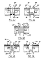
- FIGS. 9 through 14 illustrate various alternative arrangements for preventing oil cavitation in the secondary pump 38 at high speed by continuously supplying engine oil pressure to the secondary pump's recirculation circuit when the secondary pump is bypassed and not providing engine fluid to the load.
- FIG. 9 illustrates a schematic illustration of an alternate flow circuit and fluid control valve
- FIG. 11 illustrates a portion of the flow control valve.
- the operation of the fluid control valve mechanism 54 shown in FIGS. 9 and 11 , is the same as described above in connection with FIGS. 1 through 8 .
- the cross-over port 94 has been eliminated from the flow circuit.
- a pair of bleeder notches 150 are formed in the valve housing 80 at the inlet of the secondary outlet passageway 76 and the outlet of the secondary outlet passageway 76 .
- the bleeder notches 150 allow leak back from the secondary outlet passageway 76 to the recirculation passage 92 to ensure a continuous supply of engine oil at the secondary pump 38 during high speed operation.
- FIG. 10 illustrates a preferred embodiment for accomplishing leak back of engine fluid to prevent cavitation of the secondary pump 36 .
- the cross-over port 94 is preferably eliminated from the circuit.
- an annular groove 152 is formed in the surface of the first plunger portion 86 to allow for the necessary leak back function.
- the annular groove 152 allows fluid to leak back to the recirculation passageway 92 of the secondary pump 36 to prevent cavitation of the secondary pump 36 in the event of any significant oil loss or leakage.
- the annular groove 152 is formed in the center of the first plunger portion 86 , but can be formed anywhere along its surface.
- the annular groove 152 is sized to allow fluid leak back, but also prevent excess flow of fluid from the outlet of the secondary outlet passageway 76 to the inlet of the secondary outlet passageway 76 . While a single annular grove 152 is illustrated, it should be understood that a plurality of annular grooves may alternatively be employed. Further, the annular groove 152 may take on any of a variety of shapes, including rounded or rectangular.
- FIG. 12 illustrates another embodiment for accomplishing leak back without the inclusion of a cross-over port 94 .
- bleeder notches 154 are formed in the surface of the first plunger portion 86 . It should be understood that the shape and location of the bleeder notches is not critical so long as they are sized to prevent excess flow of fluid from the outlet of the secondary outlet passageway 76 to the inlet of the secondary outlet passageway 76 . It will be understood by one of ordinary skill in the art that the size of the various bleeder notches and other leak back mechanisms will have similar flow restrictions.
- the bleeder notches 154 formed in the plunger portion perform the same leak back function as the bleeder notches 150 the and annular groove 152 in FIG. 10 .
- FIG. 13 illustrates a further alternative embodiment for accomplishing leak back of engine fluid to prevent cavitation of the secondary pump 36 without the use of a cross-over port 94 .
- a hole or passageway 156 is formed through the first plunger portion 86 to allow leak back of engine fluid from the outlet of secondary outlet passageway 76 to the inlet of the secondary outlet passageway 76 .
- the passageway 156 performs the same function as the bleeder notches 150 , 154 , and the annular groove 152 and is subject to the same size restrictions.
- FIG. 14 illustrates yet another alternative embodiment for accomplishing leak back of engine fluid to prevent cavitation of the secondary pump 36 without the use of a cross-over port 94 .
- the first plunger portion 86 is positioned such that its ends cover the entire secondary outlet passageway 76 to block the flow of fluid therethrough. While various leak back mechanisms are formed in and around the first plunger portion, the first plunger portion 86 still blocks the secondary outlet passageway 76 with these configurations. As shown in FIG. 14 , the first plunger portion 86 is designed to cover substantially all of the secondary outlet passage 76 when the valve member is in a fully closed position at high engine speed.
- a leak back opening 158 is formed between the first plunger portion 86 and the walls of the secondary outlet passage 76 to allow engine fluid to leak back.
- the leak back opening 158 is relatively small and is sized to allow leak back of engine oil, but also prevents excess flow of fluid from the outlet of the secondary outlet passageway 76 to the inlet of the secondary outlet passageway 76 .
Abstract
Description
Claims (24)
Priority Applications (6)
| Application Number | Priority Date | Filing Date | Title |
|---|---|---|---|
| US09/489,525 US7086366B1 (en) | 1999-04-20 | 2000-01-21 | Energy efficient fluid pump |
| PCT/US2000/040762 WO2001053678A1 (en) | 2000-01-21 | 2000-08-29 | Improved energy efficient fluid pump |
| KR1020027009338A KR100753897B1 (en) | 2000-01-21 | 2000-08-29 | Improved energy efficient fluid pump |
| GB0216675A GB2378482B (en) | 2000-01-21 | 2000-08-29 | Improved energy efficient fluid pump |
| AU2000280357A AU2000280357A1 (en) | 2000-01-21 | 2000-08-29 | Improved energy efficient fluid pump |
| DE10085413T DE10085413T1 (en) | 2000-01-21 | 2000-08-29 | Improved energy-efficient fluid pump |
Applications Claiming Priority (2)
| Application Number | Priority Date | Filing Date | Title |
|---|---|---|---|
| US13010399P | 1999-04-20 | 1999-04-20 | |
| US09/489,525 US7086366B1 (en) | 1999-04-20 | 2000-01-21 | Energy efficient fluid pump |
Publications (1)
| Publication Number | Publication Date |
|---|---|
| US7086366B1 true US7086366B1 (en) | 2006-08-08 |
Family
ID=36758456
Family Applications (1)
| Application Number | Title | Priority Date | Filing Date |
|---|---|---|---|
| US09/489,525 Expired - Lifetime US7086366B1 (en) | 1999-04-20 | 2000-01-21 | Energy efficient fluid pump |
Country Status (1)
| Country | Link |
|---|---|
| US (1) | US7086366B1 (en) |
Cited By (18)
| Publication number | Priority date | Publication date | Assignee | Title |
|---|---|---|---|---|
| US20070039782A1 (en) * | 2005-07-28 | 2007-02-22 | J.C. Bamford Excavators Limited | Providing lubricant to an engine |
| US20080115661A1 (en) * | 2006-09-14 | 2008-05-22 | Luk Lamellen Und Kupplungsbau Beteiligungs Kg | Hydraulic system for supplying a hydraulic fluid to a component |
| US20080273992A1 (en) * | 2007-05-03 | 2008-11-06 | Metaldyne Company Llc. | Cavitation-deterring energy-efficient fluid pump system and method of operation |
| US20110174244A1 (en) * | 2010-11-02 | 2011-07-21 | Ford Global Technologies, Llc | Accessory drive for a stop/start vehicle |
| US20110176931A1 (en) * | 2010-11-02 | 2011-07-21 | Ford Global Technologies, Llc | Efficient vacuum for a vehicle |
| US7997885B2 (en) | 2007-12-03 | 2011-08-16 | Carefusion 303, Inc. | Roots-type blower reduced acoustic signature method and apparatus |
| US20110283966A1 (en) * | 2010-05-20 | 2011-11-24 | GM Global Technology Operations LLC | Oil pump module having an oil pump module housing |
| US8118024B2 (en) | 2003-08-04 | 2012-02-21 | Carefusion 203, Inc. | Mechanical ventilation system utilizing bias valve |
| US8156937B2 (en) | 2003-08-04 | 2012-04-17 | Carefusion 203, Inc. | Portable ventilator system |
| US8297279B2 (en) | 2003-08-04 | 2012-10-30 | Carefusion 203, Inc. | Portable ventilator system |
| US8677995B2 (en) | 2003-08-04 | 2014-03-25 | Carefusion 203, Inc. | Compressor control system for a portable ventilator |
| US20140251273A1 (en) * | 2013-03-08 | 2014-09-11 | GM Global Technology Operations LLC | Oil pump control systems and methods for noise minimization |
| US8888711B2 (en) | 2008-04-08 | 2014-11-18 | Carefusion 203, Inc. | Flow sensor |
| US9051991B2 (en) | 2011-08-08 | 2015-06-09 | Ford Global Technologies, Llc | Internal combustion engine with mass balancing and method for operating such an internal combustion engine |
| US9103246B2 (en) | 2010-11-02 | 2015-08-11 | Ford Global Technologies, Llc | System and method for reducing vacuum degradation in a vehicle |
| US20150330519A1 (en) * | 2011-10-24 | 2015-11-19 | Eaton Corporation | Line pressure valve to selectively control distribution of pressurized fluid |
| US20160160714A1 (en) * | 2013-09-26 | 2016-06-09 | United Technologies Corporation | Gas turbine engine with split lubrication system |
| JP2021008830A (en) * | 2019-06-28 | 2021-01-28 | 三菱自動車工業株式会社 | Engine oil supply device |
Citations (22)
| Publication number | Priority date | Publication date | Assignee | Title |
|---|---|---|---|---|
| FR904757A (en) | 1944-05-30 | 1945-11-15 | Cem Comp Electro Mec | Device for automatically increasing at slow speeds the flow of lubricating oil to auxiliaries operated by variable speed machines |
| US3716308A (en) | 1970-01-28 | 1973-02-13 | Bosch Gmbh Robert | Hydraulic system |
| US3951575A (en) | 1972-07-10 | 1976-04-20 | Kabushiki Kaisha Komatsu Seisakusho | Controlled output gear pump and motor |
| US4002027A (en) | 1973-10-01 | 1977-01-11 | Tyrone Hydraulics, Inc. | Multiple pump control system |
| US4027699A (en) * | 1974-10-02 | 1977-06-07 | Stal-Laval Turbin Ab | Fluid distribution valve |
| US4122868A (en) * | 1975-01-24 | 1978-10-31 | International Harvester Company | Hydraulic valve assembly having an axial flow force balanced spool |
| US4245964A (en) | 1978-11-08 | 1981-01-20 | United Technologies Corporation | Efficiency fluid pumping system including sequential unloading of a plurality of pumps by a single pressure responsive control valve |
| US4306840A (en) | 1978-06-10 | 1981-12-22 | Zahnradfabrik Friedrichshafen, Ag. | Automatic connecting valve for hydraulic systems |
| US4639202A (en) | 1985-02-06 | 1987-01-27 | Mahanay Joseph W | Gerotor device with dual valving plates |
| US4645026A (en) | 1984-10-31 | 1987-02-24 | Trw Cam Gears Limited | Vehicle control system |
| US4703724A (en) | 1986-05-29 | 1987-11-03 | Chrysler Motors Corporation | Engine balancing device with a lubricant side discharge |
| US4813858A (en) | 1986-05-20 | 1989-03-21 | Mannesmann Rexroth Gmbh | Gerotor pump with pressure valve and suction opening for each pressure chamber |
| US4832579A (en) | 1985-01-22 | 1989-05-23 | Peter Norton | Plural hydraulic pump system with automatic displacement control and pressure relief valve |
| US5017101A (en) | 1988-03-29 | 1991-05-21 | Jeffrey White | Selectively operated gerotor device |
| JPH0417286A (en) | 1990-05-09 | 1992-01-22 | Sumitomo Electric Ind Ltd | Thunderbolt detecting and reporting apparatus |
| US5123628A (en) * | 1991-05-17 | 1992-06-23 | Jim Yu | Water saving valve |
| US5460211A (en) | 1994-02-23 | 1995-10-24 | Minati; Frank E. | Component hydraulic log splitter |
| US5464330A (en) | 1993-03-09 | 1995-11-07 | Applied Power Inc. | Cyclic hydraulic pump improvements |
| US5492034A (en) | 1993-06-09 | 1996-02-20 | Eaton Corporation | Twin countershaft transmission and improved power take-off arrangement therefor |
| US5535643A (en) | 1993-11-12 | 1996-07-16 | General Motors Corporation | Anti-rattle engine balancer which drives associated oil pump |
| US5791309A (en) | 1996-02-06 | 1998-08-11 | Honda Giken Kogyo Kabushiki Kaisha | Balancer shaft supporting structure in engine |
| US5918573A (en) | 1997-05-02 | 1999-07-06 | Killion; David L. | Energy efficient fluid pump |
-
2000
- 2000-01-21 US US09/489,525 patent/US7086366B1/en not_active Expired - Lifetime
Patent Citations (22)
| Publication number | Priority date | Publication date | Assignee | Title |
|---|---|---|---|---|
| FR904757A (en) | 1944-05-30 | 1945-11-15 | Cem Comp Electro Mec | Device for automatically increasing at slow speeds the flow of lubricating oil to auxiliaries operated by variable speed machines |
| US3716308A (en) | 1970-01-28 | 1973-02-13 | Bosch Gmbh Robert | Hydraulic system |
| US3951575A (en) | 1972-07-10 | 1976-04-20 | Kabushiki Kaisha Komatsu Seisakusho | Controlled output gear pump and motor |
| US4002027A (en) | 1973-10-01 | 1977-01-11 | Tyrone Hydraulics, Inc. | Multiple pump control system |
| US4027699A (en) * | 1974-10-02 | 1977-06-07 | Stal-Laval Turbin Ab | Fluid distribution valve |
| US4122868A (en) * | 1975-01-24 | 1978-10-31 | International Harvester Company | Hydraulic valve assembly having an axial flow force balanced spool |
| US4306840A (en) | 1978-06-10 | 1981-12-22 | Zahnradfabrik Friedrichshafen, Ag. | Automatic connecting valve for hydraulic systems |
| US4245964A (en) | 1978-11-08 | 1981-01-20 | United Technologies Corporation | Efficiency fluid pumping system including sequential unloading of a plurality of pumps by a single pressure responsive control valve |
| US4645026A (en) | 1984-10-31 | 1987-02-24 | Trw Cam Gears Limited | Vehicle control system |
| US4832579A (en) | 1985-01-22 | 1989-05-23 | Peter Norton | Plural hydraulic pump system with automatic displacement control and pressure relief valve |
| US4639202A (en) | 1985-02-06 | 1987-01-27 | Mahanay Joseph W | Gerotor device with dual valving plates |
| US4813858A (en) | 1986-05-20 | 1989-03-21 | Mannesmann Rexroth Gmbh | Gerotor pump with pressure valve and suction opening for each pressure chamber |
| US4703724A (en) | 1986-05-29 | 1987-11-03 | Chrysler Motors Corporation | Engine balancing device with a lubricant side discharge |
| US5017101A (en) | 1988-03-29 | 1991-05-21 | Jeffrey White | Selectively operated gerotor device |
| JPH0417286A (en) | 1990-05-09 | 1992-01-22 | Sumitomo Electric Ind Ltd | Thunderbolt detecting and reporting apparatus |
| US5123628A (en) * | 1991-05-17 | 1992-06-23 | Jim Yu | Water saving valve |
| US5464330A (en) | 1993-03-09 | 1995-11-07 | Applied Power Inc. | Cyclic hydraulic pump improvements |
| US5492034A (en) | 1993-06-09 | 1996-02-20 | Eaton Corporation | Twin countershaft transmission and improved power take-off arrangement therefor |
| US5535643A (en) | 1993-11-12 | 1996-07-16 | General Motors Corporation | Anti-rattle engine balancer which drives associated oil pump |
| US5460211A (en) | 1994-02-23 | 1995-10-24 | Minati; Frank E. | Component hydraulic log splitter |
| US5791309A (en) | 1996-02-06 | 1998-08-11 | Honda Giken Kogyo Kabushiki Kaisha | Balancer shaft supporting structure in engine |
| US5918573A (en) | 1997-05-02 | 1999-07-06 | Killion; David L. | Energy efficient fluid pump |
Cited By (30)
| Publication number | Priority date | Publication date | Assignee | Title |
|---|---|---|---|---|
| US8118024B2 (en) | 2003-08-04 | 2012-02-21 | Carefusion 203, Inc. | Mechanical ventilation system utilizing bias valve |
| US8522780B2 (en) | 2003-08-04 | 2013-09-03 | Carefusion 203, Inc. | Portable ventilator system |
| US8677995B2 (en) | 2003-08-04 | 2014-03-25 | Carefusion 203, Inc. | Compressor control system for a portable ventilator |
| US8683997B2 (en) | 2003-08-04 | 2014-04-01 | Carefusion 203, Inc. | Portable ventilator system |
| US10118011B2 (en) | 2003-08-04 | 2018-11-06 | Carefusion 203, Inc. | Mechanical ventilation system utilizing bias valve |
| US8156937B2 (en) | 2003-08-04 | 2012-04-17 | Carefusion 203, Inc. | Portable ventilator system |
| US8627819B2 (en) | 2003-08-04 | 2014-01-14 | Carefusion 203, Inc. | Portable ventilator system |
| US8297279B2 (en) | 2003-08-04 | 2012-10-30 | Carefusion 203, Inc. | Portable ventilator system |
| US7516729B2 (en) * | 2005-07-28 | 2009-04-14 | J.C. Bamford Excavation Limited | Providing lubricant to an engine |
| US20070039782A1 (en) * | 2005-07-28 | 2007-02-22 | J.C. Bamford Excavators Limited | Providing lubricant to an engine |
| US20080115661A1 (en) * | 2006-09-14 | 2008-05-22 | Luk Lamellen Und Kupplungsbau Beteiligungs Kg | Hydraulic system for supplying a hydraulic fluid to a component |
| US20080273992A1 (en) * | 2007-05-03 | 2008-11-06 | Metaldyne Company Llc. | Cavitation-deterring energy-efficient fluid pump system and method of operation |
| US7997885B2 (en) | 2007-12-03 | 2011-08-16 | Carefusion 303, Inc. | Roots-type blower reduced acoustic signature method and apparatus |
| US8888711B2 (en) | 2008-04-08 | 2014-11-18 | Carefusion 203, Inc. | Flow sensor |
| US9375166B2 (en) | 2008-04-08 | 2016-06-28 | Carefusion 203, Inc. | Flow sensor |
| US9713438B2 (en) | 2008-04-08 | 2017-07-25 | Carefusion 203, Inc. | Flow sensor |
| US20110283966A1 (en) * | 2010-05-20 | 2011-11-24 | GM Global Technology Operations LLC | Oil pump module having an oil pump module housing |
| US8267072B2 (en) | 2010-11-02 | 2012-09-18 | Ford Global Technologies, Llc | Efficient vacuum for a vehicle |
| US20110174244A1 (en) * | 2010-11-02 | 2011-07-21 | Ford Global Technologies, Llc | Accessory drive for a stop/start vehicle |
| US8355859B2 (en) | 2010-11-02 | 2013-01-15 | Ford Global Technologies, Llc | Accessory drive for a stop/start vehicle |
| US9103246B2 (en) | 2010-11-02 | 2015-08-11 | Ford Global Technologies, Llc | System and method for reducing vacuum degradation in a vehicle |
| US20110176931A1 (en) * | 2010-11-02 | 2011-07-21 | Ford Global Technologies, Llc | Efficient vacuum for a vehicle |
| US8640680B2 (en) | 2010-11-02 | 2014-02-04 | Ford Global Technologies, Llc | Efficient vacuum for a vehicle |
| US9051991B2 (en) | 2011-08-08 | 2015-06-09 | Ford Global Technologies, Llc | Internal combustion engine with mass balancing and method for operating such an internal combustion engine |
| US9488285B2 (en) * | 2011-10-24 | 2016-11-08 | Eaton Corporation | Line pressure valve to selectively control distribution of pressurized fluid |
| US20150330519A1 (en) * | 2011-10-24 | 2015-11-19 | Eaton Corporation | Line pressure valve to selectively control distribution of pressurized fluid |
| US9353655B2 (en) * | 2013-03-08 | 2016-05-31 | GM Global Technology Operations LLC | Oil pump control systems and methods for noise minimization |
| US20140251273A1 (en) * | 2013-03-08 | 2014-09-11 | GM Global Technology Operations LLC | Oil pump control systems and methods for noise minimization |
| US20160160714A1 (en) * | 2013-09-26 | 2016-06-09 | United Technologies Corporation | Gas turbine engine with split lubrication system |
| JP2021008830A (en) * | 2019-06-28 | 2021-01-28 | 三菱自動車工業株式会社 | Engine oil supply device |
Similar Documents
| Publication | Publication Date | Title |
|---|---|---|
| US5918573A (en) | Energy efficient fluid pump | |
| US7086366B1 (en) | Energy efficient fluid pump | |
| EP0785361B1 (en) | Oil pump apparatus | |
| US5738501A (en) | Internal gear pump | |
| US9017205B2 (en) | Transmission unit | |
| JP2003336513A (en) | Lubrication system for engine | |
| CN102549241A (en) | Device for variably adjusting the control times of gas exchange valves of an internal combustion engine | |
| JPH0483955A (en) | Working pressure circuit for automatic transmission | |
| JP2001317320A (en) | Lubricating device for internal combustion engine | |
| JPH08144965A (en) | Pump delivery control device for automatic transmission | |
| US9546728B2 (en) | Balanced binary pump for CVT transmission | |
| EP0875678B1 (en) | Oil pump control valve | |
| US20030136371A1 (en) | Energy efficient fluid pump system | |
| US20100059315A1 (en) | High efficiency lubrication pump | |
| US5685266A (en) | Ring gear pumps | |
| US6478549B1 (en) | Hydraulic pump with speed dependent recirculation valve | |
| WO2001053678A1 (en) | Improved energy efficient fluid pump | |
| JP5940844B2 (en) | Hydraulic hybrid vehicle | |
| JP2001165064A (en) | Oil pump device | |
| KR101163371B1 (en) | Oil pumps and balance shafts | |
| JP2003193819A (en) | Oil pump device of internal combustion engine | |
| JP4327466B2 (en) | Engine oil supply device | |
| JP3608688B2 (en) | Oil pump device | |
| JP6705185B2 (en) | Oil supply device | |
| KR100359869B1 (en) | Oil pump |
Legal Events
| Date | Code | Title | Description |
|---|---|---|---|
| AS | Assignment |
Owner name: SIMPSON INDUSTRIES, INC., MICHIGAN Free format text: ASSIGNMENT OF ASSIGNORS INTEREST;ASSIGNOR:KILLION, DAVID L.;REEL/FRAME:010868/0576 Effective date: 20000607 |
|
| AS | Assignment |
Owner name: METALDYNE MACHINING AND ASSEMBLY COMPANY INC., MIC Free format text: CHANGE OF NAME;ASSIGNOR:SIMPSON INDUSTRIES, INC.;REEL/FRAME:013991/0723 Effective date: 20010319 |
|
| STCF | Information on status: patent grant |
Free format text: PATENTED CASE |
|
| AS | Assignment |
Owner name: JPMORGAN CHASE BANK, N.A. AS COLLATERAL AGENT, TEX Free format text: SECURITY AGREEMENT;ASSIGNORS:METALDYNE COMPANY LLC;METALDYNE CORPORATION;METALDYNE MACHINING AND ASSEMBLY COMPANY, INC.;AND OTHERS;REEL/FRAME:018350/0097 Effective date: 20061003 |
|
| AS | Assignment |
Owner name: METALDYNE CORPORATION, MICHIGAN Free format text: TERMINATION AND RELEASE OF SECURITY INTEREST IN PATENT RIGHTS;ASSIGNOR:JPMORGAN CHASE BANK, N.A., AS COLLATERAL AGENT;REEL/FRAME:018861/0474 Effective date: 20070111 Owner name: METALDYNE TUBULAR PRODUCTS, INC., MICHIGAN Free format text: TERMINATION AND RELEASE OF SECURITY INTEREST IN PATENT RIGHTS;ASSIGNOR:JPMORGAN CHASE BANK, N.A., AS COLLATERAL AGENT;REEL/FRAME:018861/0474 Effective date: 20070111 Owner name: METALDYNE COMPANY LLC, MICHIGAN Free format text: TERMINATION AND RELEASE OF SECURITY INTEREST IN PATENT RIGHTS;ASSIGNOR:JPMORGAN CHASE BANK, N.A., AS COLLATERAL AGENT;REEL/FRAME:018861/0474 Effective date: 20070111 Owner name: JPMORGAN CHASE BANK, N.A., AS COLLATERAL AGENT, TE Free format text: SECURITY AGREEMENT;ASSIGNOR:METALDYNE MACHINING AND ASSEMBLY COMPANY, INC.;REEL/FRAME:018861/0761 Effective date: 20070111 Owner name: METALDYNE MACHINING AND ASSEMBLY COMPANY, INC., MI Free format text: TERMINATION AND RELEASE OF SECURITY INTEREST IN PATENT RIGHTS;ASSIGNOR:JPMORGAN CHASE BANK, N.A., AS COLLATERAL AGENT;REEL/FRAME:018861/0474 Effective date: 20070111 Owner name: DEUTSCHE BANK AG, NEW YORK BRANCH, AS COLLATERAL A Free format text: SECURITY AGREEMENT;ASSIGNOR:METALDYNE MACHINING AND ASSEMBLY COMPANY, INC.;REEL/FRAME:018866/0153 Effective date: 20070111 Owner name: NC-M CHASSIS SYSTEMS, LLC, MICHIGAN Free format text: TERMINATION AND RELEASE OF SECURITY INTEREST IN PATENT RIGHTS;ASSIGNOR:JPMORGAN CHASE BANK, N.A., AS COLLATERAL AGENT;REEL/FRAME:018861/0474 Effective date: 20070111 Owner name: METALDYNE SINTERED COMPONENTS, LLC, MICHIGAN Free format text: TERMINATION AND RELEASE OF SECURITY INTEREST IN PATENT RIGHTS;ASSIGNOR:JPMORGAN CHASE BANK, N.A., AS COLLATERAL AGENT;REEL/FRAME:018861/0474 Effective date: 20070111 |
|
| AS | Assignment |
Owner name: THE BANK OF NEW YORK TRUST COMPANY, N.A., ILLINOIS Free format text: SECURITY AGREEMENT;ASSIGNOR:METALDYNE MACHINING AND ASSEMBLY COMPANY, INC.;REEL/FRAME:018951/0457 Effective date: 20070111 Owner name: THE BANK OF NEW YORK TRUST COMPANY, N.A., ILLINOIS Free format text: SECURITY AGREEMENT;ASSIGNOR:METALDYNE MACHINING AND ASSEMBLY COMPANY, INC.;REEL/FRAME:018951/0427 Effective date: 20070111 |
|
| AS | Assignment |
Owner name: METALDYNE MACHINING AND ASSEMBLY COMPANY, INC., MI Free format text: PATENT RELEASE;ASSIGNOR:THE BANK OF NEW YORK MELLON TRUST COMPANY, N.A.;REEL/FRAME:022177/0989 Effective date: 20081125 Owner name: METALDYNE MACHINING AND ASSEMBLY COMPANY, INC., MI Free format text: PATENT RELEASE;ASSIGNOR:THE BANK OF NEW YORK MELLON TRUST COMPANY, N.A.;REEL/FRAME:022177/0979 Effective date: 20081125 |
|
| AS | Assignment |
Owner name: METALDYNE BSM, LLC, MICHIGAN Free format text: ASSIGNMENT OF ASSIGNORS INTEREST;ASSIGNORS:METALDYNE CORPORATION;METALDYNE COMPANY LLC;METALDYNE SINTERED COMPONENTS, LLC;AND OTHERS;REEL/FRAME:023401/0221 Effective date: 20091016 |
|
| AS | Assignment |
Owner name: WILMINGTON TRUST FSB, AS COLLATERAL AGENT, MINNESO Free format text: FIRST LIEN SECURITY INTEREST;ASSIGNORS:METALDYNE, LLC;METALDYNE CHASSIS PRODUCTS, LLC;METALDYNE TUBULAR COMPONENTS, LLC;AND OTHERS;REEL/FRAME:023409/0063 Effective date: 20091016 Owner name: WILMINGTON TRUST FSB, AS COLLATERAL AGENT,MINNESOT Free format text: FIRST LIEN SECURITY INTEREST;ASSIGNORS:METALDYNE, LLC;METALDYNE CHASSIS PRODUCTS, LLC;METALDYNE TUBULAR COMPONENTS, LLC;AND OTHERS;REEL/FRAME:023409/0063 Effective date: 20091016 |
|
| AS | Assignment |
Owner name: WILMINGTON TRUST FSB, AS COLLATERAL AGENT, MINNESO Free format text: SECOND LIEN SECURITY INTEREST;ASSIGNORS:METALDYNE, LLC;METALDYNE CHASSIS PRODUCTS, LLC;METALDYNE TUBULAR COMPONENTS, LLC;AND OTHERS;REEL/FRAME:023409/0512 Effective date: 20091016 Owner name: WILMINGTON TRUST FSB, AS COLLATERAL AGENT,MINNESOT Free format text: SECOND LIEN SECURITY INTEREST;ASSIGNORS:METALDYNE, LLC;METALDYNE CHASSIS PRODUCTS, LLC;METALDYNE TUBULAR COMPONENTS, LLC;AND OTHERS;REEL/FRAME:023409/0512 Effective date: 20091016 |
|
| AS | Assignment |
Owner name: METALDYNE BSM, LLC, MICHIGAN Free format text: BANKRUPTCY COURT ORDER RELEASING ALL LIENS, INCLUDING THE SECURITY INTEREST RECORDED AT REEL/FRAME 018866/0153;ASSIGNOR:DEUTSCHE BANK AG, NEW YORK BRANCH, AS COLLATERAL AGENT;REEL/FRAME:023586/0629 Effective date: 20090819 Owner name: METALDYNE BSM, LLC, MICHIGAN Free format text: BANKRUPTCY COURT ORDER RELEASING ALL LIENS, INCLUDING THE SECURITY INTEREST RECORDED AT REEL/FRAME 018350/0097;ASSIGNOR:JPMORGAN CHASE BANK, N.A., AS COLLATERAL AGENT;REEL/FRAME:023586/0902 Effective date: 20090819 Owner name: METALDYNE BSM, LLC, MICHIGAN Free format text: BANKRUPTCY COURT ORDER RELEASING ALL LIENS, INCLUDING THE SECURITY INTEREST RECORDED AT REEL/FRAME 018861/0761;ASSIGNOR:JPMORGAN CHASE BANK, N.A., AS COLLATERAL AGENT;REEL/FRAME:023586/0563 Effective date: 20090819 |
|
| FPAY | Fee payment |
Year of fee payment: 4 |
|
| AS | Assignment |
Owner name: BANK OF AMERICA, N.A., AS AGENT,CONNECTICUT Free format text: SECURITY AGREEMENT;ASSIGNOR:METALDYNE BSM, LLC;REEL/FRAME:024170/0983 Effective date: 20100219 Owner name: BANK OF AMERICA, N.A., AS AGENT, CONNECTICUT Free format text: SECURITY AGREEMENT;ASSIGNOR:METALDYNE BSM, LLC;REEL/FRAME:024170/0983 Effective date: 20100219 |
|
| AS | Assignment |
Owner name: METALDYNE, LLC, MICHIGAN Free format text: RELEASE OF SECURITY INTEREST IN PATENTS SECOND LIEN RECORDED AT REEL/FRAME 023409/0512;ASSIGNOR:WILMINGTON TRUST FSB, AS COLLATERAL AGENT;REEL/FRAME:025183/0442 Effective date: 20101022 Owner name: METALDYNE TUBULUAR COMPONENTS, LLC, MICHIGAN Free format text: RELEASE OF SECURITY INTEREST IN PATENTS FIRST LIEN RECORDED AT REEL/FRAME 023409/0063;ASSIGNOR:WILMINGTON TRUST FSB, AS COLLATERAL AGENT;REEL/FRAME:025182/0986 Effective date: 20101022 Owner name: METALDYNE TUBULUAR COMPONENTS, LLC, MICHIGAN Free format text: RELEASE OF SECURITY INTEREST IN PATENTS SECOND LIEN RECORDED AT REEL/FRAME 023409/0512;ASSIGNOR:WILMINGTON TRUST FSB, AS COLLATERAL AGENT;REEL/FRAME:025183/0442 Effective date: 20101022 Owner name: METALDYNE, LLC, MICHIGAN Free format text: RELEASE OF SECURITY INTEREST IN PATENTS FIRST LIEN RECORDED AT REEL/FRAME 023409/0063;ASSIGNOR:WILMINGTON TRUST FSB, AS COLLATERAL AGENT;REEL/FRAME:025182/0986 Effective date: 20101022 Owner name: METALDYNE BSM, LLC, MICHIGAN Free format text: RELEASE OF SECURITY INTEREST IN PATENTS SECOND LIEN RECORDED AT REEL/FRAME 023409/0512;ASSIGNOR:WILMINGTON TRUST FSB, AS COLLATERAL AGENT;REEL/FRAME:025183/0442 Effective date: 20101022 Owner name: METALDYNE BSM, LLC, MICHIGAN Free format text: RELEASE OF SECURITY INTEREST IN PATENTS FIRST LIEN RECORDED AT REEL/FRAME 023409/0063;ASSIGNOR:WILMINGTON TRUST FSB, AS COLLATERAL AGENT;REEL/FRAME:025182/0986 Effective date: 20101022 |
|
| AS | Assignment |
Owner name: DEUTSCHE BANK TRUST COMPANY AMERICAS, AS COLLATERA Free format text: PATENT SECURITY AGREEMENT;ASSIGNOR:METALDYNE BSM, LLC;REEL/FRAME:025192/0655 Effective date: 20101022 |
|
| AS | Assignment |
Owner name: METALDYNE BSM, LLC, MICHIGAN Free format text: RELESE OF SECURITY INTEREST - FIRST LIEN BSM PATENTS;ASSIGNOR:DEUTSCHE BANK TRUST COMPANY AMERICAS, AS COLLATERAL AGENT;REEL/FRAME:026362/0365 Effective date: 20110518 Owner name: DEUTSCHE BANK TRUST COMPANY AMERICAS, AS COLLATERA Free format text: SECURITY AGREEMENT - METALDYNE BSM PATENTS;ASSIGNOR:METALDYNE BSM, LLC;REEL/FRAME:026361/0847 Effective date: 20110518 |
|
| AS | Assignment |
Owner name: BANK OF AMERICA, N.A., AS COLLATERAL AGENT, TEXAS Free format text: SECURITY AGREEMENT;ASSIGNOR:METALDYNE BSM, LLC;REEL/FRAME:029495/0341 Effective date: 20121218 |
|
| AS | Assignment |
Owner name: METALDYNE BSM, LLC, INDIANA Free format text: TERMINATION OF SECURITY INTEREST;ASSIGNOR:DEUTSCHE BANK TRUST COMPANY AMERICAS, AS COLLATERAL AGENT;REEL/FRAME:029920/0603 Effective date: 20121218 |
|
| AS | Assignment |
Owner name: MD INVESTORS CORPORATION, MICHIGAN Free format text: TERMINATION OF SECURITY INTEREST;ASSIGNOR:BANK OF AMERICA, N.A., AS COLLATERAL AGENT;REEL/FRAME:029972/0039 Effective date: 20121218 Owner name: METALDYNE TUBULAR COMPONENTS, LLC, MICHIGAN Free format text: TERMINATION OF SECURITY INTEREST;ASSIGNOR:BANK OF AMERICA, N.A., AS COLLATERAL AGENT;REEL/FRAME:029972/0039 Effective date: 20121218 Owner name: PUNCHCRAFT MACHINING AND TOOLING, LLC, MICHIGAN Free format text: TERMINATION OF SECURITY INTEREST;ASSIGNOR:BANK OF AMERICA, N.A., AS COLLATERAL AGENT;REEL/FRAME:029972/0039 Effective date: 20121218 Owner name: METALDYNE, LLC, MICHIGAN Free format text: TERMINATION OF SECURITY INTEREST;ASSIGNOR:BANK OF AMERICA, N.A., AS COLLATERAL AGENT;REEL/FRAME:029972/0039 Effective date: 20121218 Owner name: METALDYNE BSM, LLC, INDIANA Free format text: TERMINATION OF SECURITY INTEREST;ASSIGNOR:BANK OF AMERICA, N.A., AS COLLATERAL AGENT;REEL/FRAME:029972/0039 Effective date: 20121218 Owner name: METALDYNE SINTERED RIDGWAY, LLC, PENNSYLVANIA Free format text: TERMINATION OF SECURITY INTEREST;ASSIGNOR:BANK OF AMERICA, N.A., AS COLLATERAL AGENT;REEL/FRAME:029972/0039 Effective date: 20121218 Owner name: METALDYNE M&A BLUFFTON, LLC, INDIANA Free format text: TERMINATION OF SECURITY INTEREST;ASSIGNOR:BANK OF AMERICA, N.A., AS COLLATERAL AGENT;REEL/FRAME:029972/0039 Effective date: 20121218 Owner name: METALDYNE SINTERFORGED PRODUCTS, LLC, PENNSYLVANIA Free format text: TERMINATION OF SECURITY INTEREST;ASSIGNOR:BANK OF AMERICA, N.A., AS COLLATERAL AGENT;REEL/FRAME:029972/0039 Effective date: 20121218 Owner name: METALDYNE POWERTRAIN COMPONENTS, INC., MICHIGAN Free format text: TERMINATION OF SECURITY INTEREST;ASSIGNOR:BANK OF AMERICA, N.A., AS COLLATERAL AGENT;REEL/FRAME:029972/0039 Effective date: 20121218 |
|
| FPAY | Fee payment |
Year of fee payment: 8 |
|
| AS | Assignment |
Owner name: GOLDMAN SACHS BANK USA, AS COLLATERAL AGENT, NEW Y Free format text: PATENT SECURITY AGREEMENT;ASSIGNOR:METALDYNE BSM, LLC;REEL/FRAME:034024/0359 Effective date: 20141020 |
|
| AS | Assignment |
Owner name: METALDYNE BSM, LLC, INDIANA Free format text: RELEASE OF SECURITY INTEREST (RELEASE OF 029495/0341);ASSIGNOR:BANK OF AMERICA, N.A.;REEL/FRAME:034030/0225 Effective date: 20141020 |
|
| AS | Assignment |
Owner name: METALDYNE BSM, LLC, MICHIGAN Free format text: RELEASE OF SECURITY INTEREST IN PATENTS RECORDED AT R/F 034024/0359;ASSIGNOR:GOLDMAN SACHS BANK USA, AS AGENT;REEL/FRAME:042178/0654 Effective date: 20170406 |
|
| AS | Assignment |
Owner name: JPMORGAN CHASE BANK, N.A., AS COLLATERAL AGENT, NE Free format text: SECURITY INTEREST;ASSIGNORS:AMERICAN AXLE & MANUFACTURING, INC.;CLOYES GEAR AND PRODUCTS, INC.;GREDE LLC;AND OTHERS;REEL/FRAME:042734/0001 Effective date: 20170605 Owner name: JPMORGAN CHASE BANK, N.A., AS COLLATERAL AGENT, NEW YORK Free format text: SECURITY INTEREST;ASSIGNORS:AMERICAN AXLE & MANUFACTURING, INC.;CLOYES GEAR AND PRODUCTS, INC.;GREDE LLC;AND OTHERS;REEL/FRAME:042734/0001 Effective date: 20170605 |
|
| MAFP | Maintenance fee payment |
Free format text: PAYMENT OF MAINTENANCE FEE, 12TH YEAR, LARGE ENTITY (ORIGINAL EVENT CODE: M1553) Year of fee payment: 12 |