US7084398B2 - Method and apparatus for selective axial ejection - Google Patents
Method and apparatus for selective axial ejection Download PDFInfo
- Publication number
- US7084398B2 US7084398B2 US11/122,097 US12209705A US7084398B2 US 7084398 B2 US7084398 B2 US 7084398B2 US 12209705 A US12209705 A US 12209705A US 7084398 B2 US7084398 B2 US 7084398B2
- Authority
- US
- United States
- Prior art keywords
- ions
- rod set
- electric field
- mass spectrometer
- exit
- Prior art date
- Legal status (The legal status is an assumption and is not a legal conclusion. Google has not performed a legal analysis and makes no representation as to the accuracy of the status listed.)
- Active
Links
Images


Classifications
-
- H—ELECTRICITY
- H01—ELECTRIC ELEMENTS
- H01J—ELECTRIC DISCHARGE TUBES OR DISCHARGE LAMPS
- H01J49/00—Particle spectrometers or separator tubes
- H01J49/26—Mass spectrometers or separator tubes
- H01J49/34—Dynamic spectrometers
- H01J49/42—Stability-of-path spectrometers, e.g. monopole, quadrupole, multipole, farvitrons
- H01J49/4205—Device types
- H01J49/422—Two-dimensional RF ion traps
- H01J49/4225—Multipole linear ion traps, e.g. quadrupoles, hexapoles
-
- H—ELECTRICITY
- H01—ELECTRIC ELEMENTS
- H01J—ELECTRIC DISCHARGE TUBES OR DISCHARGE LAMPS
- H01J49/00—Particle spectrometers or separator tubes
- H01J49/02—Details
- H01J49/06—Electron- or ion-optical arrangements
- H01J49/062—Ion guides
-
- H—ELECTRICITY
- H01—ELECTRIC ELEMENTS
- H01J—ELECTRIC DISCHARGE TUBES OR DISCHARGE LAMPS
- H01J49/00—Particle spectrometers or separator tubes
- H01J49/26—Mass spectrometers or separator tubes
- H01J49/34—Dynamic spectrometers
- H01J49/40—Time-of-flight spectrometers
- H01J49/401—Time-of-flight spectrometers characterised by orthogonal acceleration, e.g. focusing or selecting the ions, pusher electrode
-
- H—ELECTRICITY
- H01—ELECTRIC ELEMENTS
- H01J—ELECTRIC DISCHARGE TUBES OR DISCHARGE LAMPS
- H01J49/00—Particle spectrometers or separator tubes
- H01J49/26—Mass spectrometers or separator tubes
- H01J49/34—Dynamic spectrometers
- H01J49/42—Stability-of-path spectrometers, e.g. monopole, quadrupole, multipole, farvitrons
- H01J49/426—Methods for controlling ions
- H01J49/427—Ejection and selection methods
- H01J49/4275—Applying a non-resonant auxiliary oscillating voltage, e.g. parametric excitation
Definitions
- the present invention relates generally to mass spectrometry, and more particularly relates to a method and apparatus for selective axial ejection.
- mass spectrometers are known, and are widely used for trace analysis to determine the structure of ions. These spectrometers typically separate ions based on the mass-to-charge ratio (“m/z”) of the ions.
- a tandem mass spectrometer might include a mass selection section, followed by a fragmentation cell, and then a further mass resolving section.
- mass selection section typically in MS/MS analysis, one precursor or parent ion would be selected in the first mass selection section. The rest of the ions would be rejected in this first mass selection section. Then, this parent or precursor ion of interest would be fragmented in the fragmentation cell. These fragments are then provided to a downstream mass resolving section in which a particular fragment of interest is selected. The remainder of the fragments would typically be rejected.
- a precursor ion scan Another mode of operation of tandem mass spectrometry is called “a precursor ion scan”.
- the filtering window between an initial rod section and a downstream fragmentation cell is varied slowly to selectively admit precursor ions.
- Each of these precursor ions can than be fragmented in the fragmentation cell, and subjected to further mass analysis downstream of the fragmentation cell by other MS/MS instruments as required, to generate fragmentation spectra. From these fragmentation spectra generated for different ions, a desired fragmentation spectrum can be identified. Again, however, in this mode of operation, efficiency is quite low as most of the ions are filtered out.
- Tandem mass spectrometers may also include upstream quadrupole mass analyzers, in which RF/DC ion guides are used to transmit ions within a narrow range of m/z values to downstream “time-of-flight” (“TOF”) analyzers, in which measuring the flight time over a known path for an ion allows its m/z to be determined.
- TOF time-of-flight
- TOF analyzers can record complete mass spectra without the need for the scanning parameters of a mass filter, thus providing a better duty cycle and a higher acquisition rate (ie. a more rapid turnaround in the analysis process).
- RF ion guides are coupled with orthogonal TOF mass analyzers where the ion guide is for the purpose of transmitting ions to the TOF analyzer, or is used as a collision cell for producing fragment ions and for delivering the fragment ions (in addition to any remaining parent ions) to the TOF analyzer.
- Combining an ion guide with the orthogonal TOF analyzer is a convenient way of delivering ions to a TOF analyzer for analysis.
- a continuous stream of ions leaves a radio-frequency-only quadrupole ion guide comprising a collision cell and a mass filter and is directed to an extraction region of the TOF analyzer.
- the stream is then sampled by TOF extraction pulses for detection in the normal TOF manner.
- This mode of operation has duty cycle losses as described, for example, in a tutorial paper by Chernushevich et al., in the Journal of Mass Spectrometry, 2001, Vol. 36, 849–865, (“Chernushevich et al.”).
- the second mode of operation is described in Chernushevich et al., as well as in U.S. Pat. No. 5,689,111 and in U.S. Pat. No. 6,285,027.
- This mode involves pulsing ions out of a two-dimensional ion guide such that ions having particular m/z values (i.e., m/z values within narrowly-defined ranges) are bunched together in the extraction region of the TOF.
- This mode of operation reduces transmission losses between the ion guide and the TOF, but due to the dependence of ion velocity on the m/z ratio only ions from a small m/z range can be properly synchronized, leading to a narrow range of m/z (typical m max /m min ⁇ 2) that can be effectively detected by the TOF analyzer.
- m/z typically m max /m min ⁇ 2
- One way to avoid this loss is proposed in commonly assigned U.S. Pat. No. 6,744,043.
- an ion mobility stage is employed upstream of the TOF analyzer.
- the mobility migration time of the ions is somewhat correlated with the m/z values of the ions. This allows for adjustment of TOF window in pulsed mode so that the TOF window is always tuned for the m/z of ions that elute from the ion mobility stage.
- addition of the mobility stage to the spectrometer apparatus increases the complexity and cost of the apparatus.
- the use of pulsed ejection and corresponding continual adjustment of the TOF window prevents optimal efficiencies in cycle time, or process turnaround, for the spectrometer.
- a method of operating a mass spectrometer having an elongated rod set, the rod set having an entrance end, an exit end, a plurality of rods and a longitudinal axis.
- the method comprises: (a) admitting ions into the entrance end of the rod set; (b) producing an RF field between the plurality of rods to radially confine the ions in the rod set; (c) providing a static axial electric field within the rod set; and (d) separating the ions into a first group of ions and a second group of ions by providing an oscillating axial electric field within the rod set to counteract the static axial electric field, wherein the oscillating axial electric field varies along the longitudinal axis of the rod set.
- mass spectrometer system comprising: (a) an ion source; (b) a rod set, the rod set having a plurality of rods extending along a longitudinal axis, an entrance end for admitting ions from the ion source, and an exit end for ejecting ions traversing the longitudinal axis of the rod set; and, (c) a power supply module for producing an RF field between the plurality of rods of the rod set, wherein the power supply module is coupled to the rod set to provide a selected static axial electric field and a selected oscillating electric field such that (i) the selected oscillating axial electric field varies along the longitudinal axis of the rod set, and (ii) the selected static axial electric field and the selected oscillating axial electric field counteract each other to separate the ions into a first group of ions and a second group of ions based on a selected mass-to-charge ratio.
- FIG. 1 in a schematic view, illustrates an ion guide and sketches the potential distributions along the axis of the ion guide in accordance with a preferred embodiment of the invention
- FIG. 2 in a schematic view, illustrates an ion guide and sketches potential distributions along the axis of the ion guide in accordance with a second preferred embodiment of the invention
- FIG. 3 in a schematic view, illustrates an ion guide and sketches potential distributions along the axis of the ion guide in accordance with a third preferred embodiment of the invention
- FIG. 4 in a schematic view, illustrates an ion guide and sketches potential distributions along the axis of the ion guide in accordance with a fourth preferred embodiment of the invention
- FIG. 4 a in a schematic view, illustrates the ion guide of FIG. 4 together with individual power supply units in more detail;
- FIG. 5 in a schematic view, illustrates an ion guide in accordance with a fifth preferred aspect of the present invention
- FIG. 5 a in a schematic view, illustrates an ion guide in accordance with a sixth preferred aspect to the present invention
- FIG. 5 b in a schematic view, illustrates an ion guide in accordance with a seventh preferred aspect of the present invention
- FIG. 6 in a flowchart, illustrates a method of separating ions in accordance with a further aspect of the present invention
- FIG. 7 in a block diagram illustrates an MS/MS arrangement in accordance with an aspect of the invention
- FIG. 8 in a block diagram illustrates a second MS/MS arrangement in accordance with a further aspect of the present invention.
- FIG. 9 in a schematic view, illustrates an ion guide in accordance with a further aspect of the present invention.
- FIG. 1 there is illustrated in a schematic view, an ion guide 20 in accordance with a preferred aspect of the present invention.
- the ion guide 20 is represented by a set of rods 22 with RF voltage applied to them (in a known manner) by rod power supply 22 a to provide confinement of ions in a radial direction.
- the end of the ion guide 20 can be blocked by supplying an appropriate voltage from exit power supply 25 a to an electrode 25 .
- This exit electrode voltage can include a static DC and alternating AC components.
- the ions can be trapped in region 27 between exit electrode 25 and an additional barrier electrode 30 positioned such that it influences axial field distributions in the ion guide 20 .
- An appropriate voltage is supplied to barrier electrode 30 by power supply 30 a.
- the operating cycle of the ion guide 20 is depicted by a sketch of distributions of the potential along an axis of the ion guide 20 —shown as lines 35 , 37 and 40 in FIG. 1 .
- distribution potential 35 the ions are allowed to fill the ion guide 20 .
- a selected group of these ions is isolated from other ions in the ion guide 20 by applying an appropriate voltage to a barrier electrode 30 to trap ions of different m/z ranges on opposite sides of the barrier electrode 30 —the selected ions of interest being trapped adjoining the exit electrode 25 in region 27 .
- the distribution of potential along the axis of the ion guide in this intermediate interval is illustrated by line 37 of FIG. 1 .
- the trapped ions in region 27 can be mass selectively ejected out of the ion guide 20 by varying the amplitude of at least one of the AC or DC potential applied to the exit barrier 25 or to the main rods 22 or to both the exit barrier 25 and the main rods 22 .
- the DC potential difference between the rod offset and the exit barrier 25 is such that it creates an axial force that pulls ions towards the exit.
- the AC voltage applied to the exit barrier 25 creates a mass dependant effective force repelling ions from the exit barrier.
- the net effect of these two forces can be to push ions with m/z above a threshold determined by the amplitudes of the DC and AC voltages through the exit barrier 25 , while ions with m/z below this threshold are retained in the ion guide 20 by the exit barrier 25 .
- This mass selective axial ejection of ions is illustrated in the distribution potential 40 by stippled lines 45 indicating the different potential distributions at which ions of differing m/z are axially ejected.
- ions can be sequentially eluted out of the ion guide 20 by varying the AC and/or DC voltages applied to the exit barrier 25 or to the rods 22 or to both the exit barrier 25 and the rods 22 .
- the effective force due to the AC voltage can also depend on the frequency of the AC voltage, this frequency may also be varied in order to scan the m/z threshold for ion ejection.
- an ion guide 120 in accordance with a second preferred aspect of the present invention.
- the RF fields provided to the ion guide 120 by rod power supply 122 a are often reduced toward the exit of the ion guide 120 .
- the strength of the radial confinement of the ion beam may decline towards the exit, which may, in turn, broaden the spatial and velocity distribution of ions exiting the trap.
- unwanted coupling of motion caused by the RF field and the AC field in the fringing field region near the exit can further distort spatial and velocity distributions.
- Ion guide 120 of FIG. 2 includes features to address this problem.
- the ion guide 120 of FIG. 2 includes a set of rods 122 with RF fields applied to them in a known manner to radially confine the ions.
- the end of ion guide 120 can be blocked by application of an appropriate voltage supplied by exit power supply 125 a to each rod in segmented region 125 , which takes the place of exit barrier 25 in the ion guide 20 of FIG. 1 .
- This exit voltage can include a static DC and alternating AC components.
- Ions 127 can be trapped between segmented region 125 and an additional barrier electrode 130 positioned such that it influences axial field distributions in the ion guide 120 .
- An appropriate voltage is supplied to barrier electrode 130 by barrier power supply 130 a.
- the operating cycle of the ion guide 120 is depicted by a sketch of distributions of the potential along an axis of the ion guide 120 —shown as lines 135 , 137 and 140 in FIG. 2 .
- distribution potential 135 the ions are allowed to fill the ion guide 120 .
- barrier electrode 130 After a certain internal a selected group of these ions are isolated from other ions in the ion guide 120 by applying an appropriate voltage to barrier electrode 130 to trap ions of different m/z on opposite sides of the barrier electrode 130 —the selected ions of interest being trapped in area 127 adjoining segmented region 125 .
- the distribution of potential along the axis of ion guide 120 in this intermediate interval is illustrated by line 137 of FIG.
- the trapped ions can be mass selectively ejected out of the ion guide 120 by varying the amplitude of at least one of the AC or DC potentials applied to the segmented region of 125 or to the main rods 122 or to both the segmented region 125 and the main rods 122 .
- AC and DC potentials are then used to create an axial force and a counteracting effective force to push ions with m/z above a selected threshold through the segmented region 125 , while ions with m/z below this threshold are retained in the ion guide 120 between the segmented region 125 and the barrier electrode 130 .
- This mass selective ejection of ions is illustrated in the distribution potential 140 by stippled lines 145 , indicating the different potential distributions at which ions of differing m/z are axially rejected.
- ions can be sequentially eluted out of the ion guide 120 by varying the AC and/or DC voltages applied to the segmented region 125 or to the rods 122 or to both the segmented region 125 and the rods 122 .
- segmented region 125 radially confines the ion beam toward the exit of ion guide 120 , thereby reducing the spatial and velocity distribution of ions exiting the ion guide 120 .
- an ion guide 220 in accordance with a third preferred aspect of the present invention.
- the ion guide 220 comprises rods 222 , while a segmented electrode or region 225 provides the exit barrier at the end of the ion guide 220 .
- the same RF voltage that is applied to the rods 222 of the ion guide 220 by rod power supply 222 a is also applied to segmented electrodes 225 , 228 and 230 by segment power supplies 225 a , 228 a and 230 a respectively, to radially confine the ion beam within the ion guide 220 .
- the same RF voltage need not necessarily be applied to each of the segmented electrodes 225 , 228 and 230 as is applied to the remainder of the rods 222 , as different RF voltages and even different RF frequencies could be used at different segments, provided that these voltages and frequencies radially confine the ion beam.
- the operating cycle of the ion guide 220 of FIG. 3 is similar to the operating cycle of the ion guide 20 of FIG. 1 . That is, the ions can be trapped within the area 227 bordered by segmented region 228 between the segmented region 225 and the segmented region 230 .
- the operating cycle of the ion guide 222 is depicted by potential distributions 235 , 237 and 240 along the axis of the ion guide 220 .
- distribution potential 235 the ions are allowed to fill the ion guide 220 .
- a selected group of these ions are isolated from other ions in the ion guide 220 by applying an appropriate voltage to segmented region 230 to trap ions of different m/z ranges on opposite sides of the segmented region 230 —the selected ions of interest being trapped between segmented regions 230 and 225 .
- the distribution of potential along the axis of the ion guide in this intermediate interval is illustrated by line 237 of FIG. 3 .
- the trapped ions can be mass selectively ejected out of the ion guide 220 by varying the amplitude of at least one of the AC or DC potential applied to each of the rods in the segmented region 225 or to each of the main rods 222 or to both the segmented region 225 and the main rods.
- FIG. 4 there is illustrated in a schematic view, an ion guide 320 in accordance with a fourth preferred aspect of the present invention.
- the ion guide 320 is divided into a plurality of segments 325 .
- the exit of the ion guide 320 is located on the right side of FIG. 4 .
- the same RF voltage can be applied to each segment of the ion guide to radially confine the ion beam.
- an individual bias voltage—Ui for the i th segment for example, can be superimposed with the RF voltage to control the electrical field in the axial direction.
- Ui for the first two segments—that is, U 1 and U 2 are shown in FIG. 4 .
- each bias voltage Ui is individually selected, such that all of the bias voltages together can provide any desired profile along the axis of the ion guide 320 .
- individual bias voltages U 1 and U 2 are supplied to their respective segments by independently controllable power supplies P 1 and P 2 .
- bias voltage Ui is supplied by independently controllable power supply Pi to each rod in the rod set.
- each individual power supply comprises an associated resistor 326 and capacitor 328 .
- the resistors 326 are primarily responsible for determining the particular DC voltage applied to their respective segments, while the capacitors 328 are predominately responsible for determining the AC voltage provided to their respective segments.
- the voltage Ui(t) applied to each individual segment PSi can, as shown, also be a function of time.
- Solid line 330 represents the DC electric force that pushes ions towards the exit 327 of the ion guide 320 .
- the AC voltage applied to each segment in the plurality of segments 325 varies along the length of the ion guide 320 in such a way that it creates an effective field that acts in the opposite direction, pushing ions away from the exit 327 of ion guide 320 .
- the effective field resulting from the AC voltage diminishes towards the entrance of the ion guide 320 .
- Effective forces for ions of differing m/z are represented by dashed lines 335 , 340 and 345 .
- Dashed lines 335 , 340 and 345 have been shown, for simplicity, as straight lines; however, in actuality, these effective forces would be represented by step functions, in which the effective force remains constant over each segment in the plurality of segments 325 of the ion guide 320 , and then changes abruptly to a different effective force at a new segment.
- the dimension of each of the segments in the plurality of segments 325 along the axis of the ion guide 320 should be made as small as possible, such that these step functions approach straight lines 335 , 340 and 345 .
- Ions can be trapped in the ion guide 320 in regions where the DC or axial force in one direction balances the effective force acting in the opposite direction.
- ions having m/z such that they are subjected to the effective force represented by dashed line 335 can be trapped in region 327 of ion guide 320
- ions having m/z such that they are subjected to an effective force represented by dashed line 340 can be trapped in region 342 .
- ions having m/z such that they are subjected to the effective force represented by dashed line 345 will not be trapped given the AC and DC potentials provided in this case, but can instead be axially ejected from the ion guide 320 via exit end 327 .
- ions By changing the bias voltages applied to each segment, ions can be moved toward the exit end 327 of the ion guide 320 , and can be sequentially eluted based on m/z ratio.
- the ion guides of FIGS. 1 to 3 share a common limitation.
- the mass selective ejection region between the barrier electrode and the exit electrode or exit rod segment is quite small.
- these ions guides have a very limited capacity to space charge.
- only a very small number of ions can be allowed into the mass selective regions 27 , 127 and 227 of FIGS. 1 to 3 respectively.
- the ion guide 320 of FIG. 4 has a much greater capacity to space charge as ions of different m/z can occupy different regions of the trap, thereby reducing local charge density.
- relative variation of the axial potential can be reduced relative to the ion guides shown in FIGS. 1 to 3 , assuming that the rod diameter is the same for all cases.
- One drawback of the ion guide 320 of FIG. 4 is that it is rather complicated from an electrical point of view as it requires a number of power supplies PSi that provide independently controlled AC and DC voltages to each segment in the plurality of segments 325 and a RF voltage that would have to be applied to each segment in the plurality of segments 325 to radially confine the ion beam.
- PSi power supplies
- RF voltage that would have to be applied to each segment in the plurality of segments 325 to radially confine the ion beam.
- simpler electrical arrangements can be used to achieve variable axial fields in an ion guide, though, at the expense of flexibility in choosing axial distribution of AC and DC voltages. Different compromises between these countervailing desiderata are illustrated in the variance of FIGS. 5 , 5 a and 5 b.
- an ion guide 420 in accordance with a fifth aspect of the invention is illustrated in a schematic diagram.
- the ion guide 420 comprises a plurality of segments 425 .
- a plurality of resistive and capacitive dividers 455 are used to provide AC and DC voltages to each rod in each segment from power supply 422 .
- Each resistive and capacitive divider 455 comprises a capacitor 457 and a resistor 459 .
- each resistor 457 in the plurality of resistive and capacitive dividers 455 has the same value
- each capacitor 459 in the plurality of resistive and capacitive dividers 455 has the same value.
- a non-uniform axial field can then be provided by varying the length of the segments 425 along the axis of the ion guide 420 , as shown in FIG. 5 .
- the values of the resistors 457 and the capacitors 459 in the dividers 455 could be varied to provide the non-uniform axial field.
- the capacitors 459 predominantly define AC voltage profile along the ion guide 420
- the resistors define a DC voltage profile along the ion guide.
- FIGS. 4 and 5 represent the extreme ends of the compromise between electrical simplicity versus the ability to control variation in the axial fields supplied to the ion guide. However, a number of intermediate compromises between these extremes are possible. Two of these are illustrated in FIGS. 5 a and 5 b.
- FIG. 5 a there is illustrated in a schematic view, an ion guide 420 ′ in accordance with a sixth aspect of the present invention.
- the same reference numerals, with an apostrophe added, are used to designate elements analogous to those described above in connection with FIG. 5 .
- the description of FIG. 5 is not repeated with respect to FIG. 5 a.
- the AC voltage profile and the DC voltage profile applied to the ion guide of 420 of FIG. 5 are predetermined by the resistors 457 and capacitors 459 as well as by power supply 422 .
- the configuration of the power supply for the ion guide 420 ′ of FIG. 5 a permits the AC voltage profile, but not the DC voltage profile, to be easily changed over time (although, of course the DC applied can be varied in magnitude). That is, a single DC power supply 422 ′ is used to provide a DC voltage profile along the ion guide 420 ′.
- This DC voltage profile varies between the plurality of segments 425 ′ of the ion guide 420 ′ based on the resistance of resistors 459 ′. Thus, the shape of this voltage profile cannot be changed without also changing the resistance of resistors 459 ′.
- each segment i is linked via a capacitor 457 to an AC Power Supply I (PSi).
- PSi AC Power Supply I
- the AC voltage provided to each segment in the plurality of segments 425 ′ can be individually controlled.
- FIG. 5 b there is illustrated in a schematic view, an ion guide 420 ′′ in accordance with a seventh aspect of the invention.
- the same reference numerals, with double apostrophes added, are used to designate element analogous to those described above in connection with FIG. 5 .
- the description of FIG. 5 is not repeated with respect to FIG. 5 b.
- FIG. 5 b the situation is reversed relative to that of FIG. 5 a . That is, a single AC power supply 422 ′′ is linked via capacitors 457 ′′ to each segment in a plurality of segments 425 ′′ of the ion guide 420 ′′.
- the AC voltage profile provided to the ion guide 420 ′′ is predetermined by the values of the capacitors 457 ′′ although, of course, the magnitude of these AC voltage profiles can be changed by AC power supply 422 ′′.
- an individual and independently controllable DC i power supply is provided for each i th segment in the plurality of segments 425 ′′. This individual power supply is connected to its associated segment by a resistor 459 ′′.
- the DC voltage profile provided along the ion guide 420 ′′ can be varied over time by independently controlling the individual DC power supplies for each of the segments.
- step 502 of the flowchart of FIG. 6 ions are admitted into the entrance end of the rod set. Then, in step 504 , the ions are trapped in the rod set by producing an exit field at an exit member of the rod set adjacent to the exit end of the rod set, and by producing an RF field between the rods of the rod set to radially confine the ions in the rod set.
- step 506 a mass-to-charge ratio for separating the ions into at least two different groups of ions is selected.
- a static axial electric field and an oscillating axial electric field are provided within the rod set to separate the ions into a first group of ions and a second group of ions.
- Both the static axial electric field and the oscillating axial electric field can be produced using either or both of the exit field and RF field produced in step 504 .
- the static axial electric field is used to provide an axial force acting on the ions in a first direction substantially parallel to the longitudinal axis, while the oscillating axial electric field is used to provide an effective force acting on the ions in a second direction opposite to the first direction.
- the second direction is towards the exit end of the rod set from the entrance end.
- the effective force provided by the oscillating electric field is mass dependent. Therefore, counteraction of the axial force provided by the static axial electric field, which axial force is not mass dependent, and the effective force provided by the oscillating axial electric field, which effective force is mass dependent, can provide separation based on m/z of the ions. Please also note from the above equation that in order for the effective force to be provided, the oscillating axial electric field must vary along the longitudinal axis of the rod set.
- the static axial electric field and oscillating axial electric field can be provided in different ways.
- the static axial electric field can be provided by a DC potential difference between a DC rod offset of the RF field and the static DC component of the exit field, while the oscillating electric field is provided by the alternating AC component of the exit field.
- At least one of the oscillating axial electric field or static axial electric field can be adjusted to provide the desired separation.
- the amplitude of the oscillating axial electric field can be adjusted to change the effective force, thereby changing the m/z threshold at which separation occurs.
- the amplitude of the static axial electric field can be changed to change the m/z threshold for separation.
- the frequency of the oscillating axial electric field can be changed to change the m/z threshold for separation.
- step 512 at least one of the oscillating axial electric field or static axial electric field is adjusted based on the mass-to-charge ratio to axially eject the first group of ions, while retaining the second group of ions within the rod set.
- both the first group of ions and the second group of ions are trapped in a mass-selective ejection region of the rod set.
- the mass-selective ejection region extends from the barrier electrode toward the exit end of the rod set.
- a barrier field is provided at the barrier electrode to trap the ions in the mass-selective ejection region.
- the mass-selective ejection region is spaced from the exit end as shown in FIGS. 2 and 3 .
- the first group of ions may be trapped at a first trapping location, while the second group of ions are trapped at a second trapping location spaced from the first trapping location.
- This is a consequence of the effective force provided by the oscillating axial electric field varying relative to the axial force along the longitudinal axis of the rod set so that the effective force equals the axial force for the first group of ions at the first trapping location, and equals the axial force for the second group of ions at the second trapping location.
- This allows ion charge to be spaced along the longitudinal dimension of the rod set as different groups of ions—ions having different m/z ratios—can be trapped at different points along the length of the rod set.
- the counteracting effective force and axial force are used in an upstream mass spectrometer of a tandem mass spectrometer.
- this first group of ions is subjected to further processing within other components of the tandem mass spectrometer.
- the first group of ions may be fragmented in a fragmentation cell, and these fragments subsequently subjected to detection, or, the first group of ions may, themselves, be detected after the axial ejection step 512 .
- Detection of the first group of ions axially ejected in step 512 may be by, for example, a TOF analyzer.
- the heavier ions would be axially ejected to the TOF analyzer, while lighter ions are retained, in order to give the heavier ions a headstart on their trip through the TOF analyzer. Subsequently, the lighter ions would be axially ejected to the TOF analyzer.
- step 516 the second group of ions is axially ejected by changing at least one of the static axial electric field and the oscillating axial electric field. Then, in step 518 , similar to step 514 described above, the second group of ions would be subjected to further processing.
- tandem mass spectrometer arrangement 600 in accordance with a yet further aspect of the invention.
- the tandem mass spectrometer arrangement 600 includes an ion source 602 , which admits ions into a mass selective ejection trap 604 , such as the ion guide of any of FIGS. 4 , 4 a , 5 , 5 a and 5 b . As described above in connection with FIG. 6 , the ions are trapped in the mass selective ejection trap 604 .
- a static axial electric field and an oscillating axial electric field are provided within the mass selective ejection trap to separate the ions into a first group of ions and a second group of ions.
- the axial electric field is used to provide an axial force acting on the ions in a first direction
- the oscillating axial electric field is used to provide an effective force acting on the ions in a second direction opposite to the first direction.
- one of the effective force or axial force is used to axially eject the first group of ions from the mass selective ejection trap 604 to the fragmentation cell 606 .
- the first group of ions can be fragmented and then axially ejected and subjected to detection in mass spectrometer 608 .
- the second group of ions can be axially ejected from the mass selective ejection trap 604 to the fragmentation cell 606 for subsequent fragmentation and downstream detection by mass spectrometer 608 .
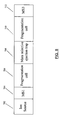
- FIG. 8 there is illustrated in a block diagram an MS/MS arrangement in accordance with a further aspect of the present invention.
- ions are ejected from an ion source 702 , and passed through a first mass spectrometer 704 for initial mass selection before being provided to a first fragmentation cell 706 .
- first mass spectrometer 704 Within fragmentation cell 707 , the ions selected in the first mass spectrometer 704 are fragmented. Any fragments are then axially ejected to mass selective ejection trap 708 , which may comprise any of the ion guides described above in connection with FIGS. 4 , 4 a , 5 , 5 a and 5 b .
- mass selective ejection trap 708 based on a selective mass-to-charge ratio, the ion fragments are divided into at least two different groups of ions using the static axial electric field and oscillating axial electric field in the manner described above. Then, a selected group in this plurality of fragment ions is axially ejected to a second fragmentation cell 710 for further fragmentation. The resulting fragments are then axially ejected to a third mass spectrometer 712 , in which they are subjected to detection.
- an ion guide 820 in accordance with a further aspect of the present invention.
- the ion guide 820 is divided into a plurality of segments 825 , an entrance segment 822 and an exit segment 824 .
- an individual bias voltage Ui can be superimposed with the RF voltage to control the electrical field in the axial direction.
- Ui for the first two segments—that is, U 1 and U 2 are shown in FIG. 9 .
- each bias voltage Ui is individually selected, such that all of the bias voltages together can provide any desired profile along the axis of the ion guide 820 .
- bias voltage Ui and U 2 can be supplied to their respective segments by independently controllable power supplies P 1 and P 2 .
- bias voltage Ui can be supplied by independently controllable power supply Pi to each segment in the rod set.
- the individual power supplies Pi for each individual segment in the plurality of segments 825 provide an AC voltage that is opposite in polarity to that of adjoining segments in the plurality of segments 825 .
- P 1 comprises a negative AC voltage applied to the first segment in the plurality of segments 825
- all of Pi, where i is odd will comprise a negative AC component
- all Pi where i is even will comprise a positive AC component.
- Applying the Gerlich formula yields the AC profile 835 , in which pseudo-potential wells are provided towards the center of each segment, and maxima are reached where adjoining segments are connected.
- the DC field 855 can be set at zero or low value while AC voltage is maintained at a properly high value. After a sufficient number of collisions the ions can precipitate in regions 842 near the bottom of the pseudo-potential wells.
- discrete groups of ions 842 can be axially centered towards the centers of individual segments, and there can be very low ion concentrations at the juncture of different segments in the plurality of segments 825 .
- the configuration of FIG. 9 axially distributes the ions along the longitudinal axis of the ion guide 820 .
- a new DC potential profile 830 sloped towards the exit is applied, by applying DC voltage to individual segments.
- This new DC potential profile 830 replaces the DC field 855 .
- the effective force due to the AC profile 835 is mass dependent, and the axial force due to the DC potential 830 is not, heavier ions can be axially ejected from the ion guide 820 while lighter ions are retained. Ions can be sequentially ejected out of the ion guide 820 by either ramping up the DC potential 830 or ramping down the amplitude of the AC potential 835 or ramping up the AC frequency, or by a combination of the above.
Abstract
Description
Claims (28)
Priority Applications (1)
| Application Number | Priority Date | Filing Date | Title |
|---|---|---|---|
| US11/122,097 US7084398B2 (en) | 2004-05-05 | 2005-05-05 | Method and apparatus for selective axial ejection |
Applications Claiming Priority (2)
| Application Number | Priority Date | Filing Date | Title |
|---|---|---|---|
| US56781704P | 2004-05-05 | 2004-05-05 | |
| US11/122,097 US7084398B2 (en) | 2004-05-05 | 2005-05-05 | Method and apparatus for selective axial ejection |
Publications (2)
| Publication Number | Publication Date |
|---|---|
| US20050253064A1 US20050253064A1 (en) | 2005-11-17 |
| US7084398B2 true US7084398B2 (en) | 2006-08-01 |
Family
ID=35241918
Family Applications (1)
| Application Number | Title | Priority Date | Filing Date |
|---|---|---|---|
| US11/122,097 Active US7084398B2 (en) | 2004-05-05 | 2005-05-05 | Method and apparatus for selective axial ejection |
Country Status (5)
| Country | Link |
|---|---|
| US (1) | US7084398B2 (en) |
| EP (1) | EP1743357B8 (en) |
| JP (2) | JP4872088B2 (en) |
| CA (1) | CA2565677A1 (en) |
| WO (1) | WO2005106922A1 (en) |
Cited By (17)
| Publication number | Priority date | Publication date | Assignee | Title |
|---|---|---|---|---|
| US20080272295A1 (en) * | 2007-05-02 | 2008-11-06 | Michael Mircea-Guna | Multipole mass filter having improved mass resolution |
| US20090014637A1 (en) * | 2005-01-17 | 2009-01-15 | Micromass Uk Limited | Mass Spectrometer |
| WO2009087402A2 (en) | 2008-01-11 | 2009-07-16 | Micromass Uk Limited | Linear ion trap |
| US20090294641A1 (en) * | 2008-05-29 | 2009-12-03 | Michael Konicek | Auxiliary drag field electrodes |
| US20090302215A1 (en) * | 2008-06-09 | 2009-12-10 | Mds Analytical Technologies, A Business Unit Of Mds Inc., Doing Business Through Its Sciex | Method of operating tandem ion traps |
| US20090302216A1 (en) * | 2008-06-09 | 2009-12-10 | Mds Analytical Technologies, A Buisness Unit Of Mds Inc, Doing Buisness Through Its Sciex Division | Multipole ion guide for providing an axial electric field whose strength increases with radial position, and a method of operating a multipole ion guide having such an axial electric field |
| US7633060B2 (en) | 2007-04-24 | 2009-12-15 | Thermo Finnigan Llc | Separation and axial ejection of ions based on m/z ratio |
| US20100078551A1 (en) * | 2008-10-01 | 2010-04-01 | MDS Analytical Technologies, a business unit of MDS, Inc. | Method, System And Apparatus For Multiplexing Ions In MSn Mass Spectrometry Analysis |
| US7858926B1 (en) * | 2002-05-31 | 2010-12-28 | Perkinelmer Health Sciences, Inc. | Mass spectrometry with segmented RF multiple ion guides in various pressure regions |
| US20130228682A1 (en) * | 2010-11-19 | 2013-09-05 | Hitachi High-Technologies Corporation | Mass spectrometer and mass spectrometry method |
| US20130240726A1 (en) * | 2010-10-08 | 2013-09-19 | Hitachi High-Technologies Corporation | Mass spectrometer |
| US8822916B2 (en) | 2008-06-09 | 2014-09-02 | Dh Technologies Development Pte. Ltd. | Method of operating tandem ion traps |
| JP2015503827A (en) * | 2011-12-29 | 2015-02-02 | ディーエイチ テクノロジーズ デベロップメント プライベート リミテッド | Ion excitation method for ion trap mass spectrometry |
| US8969799B2 (en) | 2006-12-08 | 2015-03-03 | Micromass Uk Limited | Mass spectrometer |
| US9244040B2 (en) | 2006-12-12 | 2016-01-26 | Micromass Uk Limited | Mass spectrometer |
| US9673034B2 (en) | 2006-12-08 | 2017-06-06 | Micromass Uk Limited | Mass spectrometer |
| US9679752B2 (en) | 2005-07-21 | 2017-06-13 | Micromass Uk Limited | Mass spectrometer |
Families Citing this family (31)
| Publication number | Priority date | Publication date | Assignee | Title |
|---|---|---|---|---|
| GB0416288D0 (en) * | 2004-07-21 | 2004-08-25 | Micromass Ltd | Mass spectrometer |
| GB0522327D0 (en) * | 2005-11-01 | 2005-12-07 | Micromass Ltd | Mass spectrometer |
| GB0524042D0 (en) * | 2005-11-25 | 2006-01-04 | Micromass Ltd | Mass spectrometer |
| CA2626089C (en) * | 2005-11-30 | 2016-10-04 | Mds Analytical Technologies, A Business Unit Of Mds Inc., Doing Business Through Its Sciex Division | Method and apparatus for mass selective axial transport using pulsed axial field |
| GB0608470D0 (en) | 2006-04-28 | 2006-06-07 | Micromass Ltd | Mass spectrometer |
| US7759637B2 (en) * | 2006-06-30 | 2010-07-20 | Dh Technologies Development Pte. Ltd | Method for storing and reacting ions in a mass spectrometer |
| JP5341753B2 (en) | 2006-07-10 | 2013-11-13 | マイクロマス ユーケー リミテッド | Mass spectrometer |
| US7446310B2 (en) * | 2006-07-11 | 2008-11-04 | Thermo Finnigan Llc | High throughput quadrupolar ion trap |
| US7456389B2 (en) * | 2006-07-11 | 2008-11-25 | Thermo Finnigan Llc | High throughput quadrupolar ion trap |
| WO2008009108A1 (en) * | 2006-07-19 | 2008-01-24 | Mds Analytical Technologies, A Business Unit Of Mds Inc., Doing Business Through Its Sciex Division | Method of operating a mass spectrometer to provide resonant excitation ion transfer |
| EP2084730A4 (en) * | 2006-09-28 | 2011-12-07 | Mds Analytical Tech Bu Mds Inc | Method for axial ejection and in t rap fragmentation using auxiliary electrodes in a multipole mass spectrometer |
| JP4918846B2 (en) * | 2006-11-22 | 2012-04-18 | 株式会社日立製作所 | Mass spectrometer and mass spectrometry method |
| GB0624535D0 (en) * | 2006-12-08 | 2007-01-17 | Micromass Ltd | Mass spectrometer |
| JP5262010B2 (en) * | 2007-08-01 | 2013-08-14 | 株式会社日立製作所 | Mass spectrometer and mass spectrometry method |
| US7858930B2 (en) * | 2007-12-12 | 2010-12-28 | Washington State University | Ion-trapping devices providing shaped radial electric field |
| EP2124246B1 (en) * | 2007-12-20 | 2017-03-08 | Shimadzu Corporation | Mass spectrometer |
| US7847248B2 (en) | 2007-12-28 | 2010-12-07 | Mds Analytical Technologies, A Business Unit Of Mds Inc. | Method and apparatus for reducing space charge in an ion trap |
| DE102012008972B4 (en) * | 2012-05-03 | 2018-02-01 | Bruker Daltonik Gmbh | Voltage sources for mass spectrometers |
| WO2016020789A1 (en) | 2014-08-05 | 2016-02-11 | Dh Technologies Development Pte. Ltd. | Band pass extraction from an ion trapping device and tof mass spectrometer sensitivity enhancement |
| JP6202214B2 (en) * | 2014-09-18 | 2017-09-27 | 株式会社島津製作所 | Time-of-flight mass spectrometer |
| WO2016087961A1 (en) * | 2014-12-05 | 2016-06-09 | Dh Technologies Development Pte. Ltd. | Device for ion sorting by m/z |
| CN111710588B (en) | 2015-04-23 | 2023-09-26 | 英国质谱公司 | Ion separation in ion traps |
| GB2541384B (en) * | 2015-08-14 | 2018-11-14 | Thermo Fisher Scient Bremen Gmbh | Collision cell having an axial field |
| WO2017055978A1 (en) * | 2015-10-01 | 2017-04-06 | Dh Technologies Development Pte. Ltd. | Mass-selective axial ejection linear ion trap |
| CN108475616B (en) * | 2016-01-15 | 2019-12-27 | 株式会社岛津制作所 | Orthogonal acceleration time-of-flight mass spectrometer |
| US10192730B2 (en) | 2016-08-30 | 2019-01-29 | Thermo Finnigan Llc | Methods for operating electrostatic trap mass analyzers |
| US10242857B2 (en) * | 2017-08-31 | 2019-03-26 | The University Of North Carolina At Chapel Hill | Ion traps with Y-directional ion manipulation for mass spectrometry and related mass spectrometry systems and methods |
| WO2019198010A1 (en) * | 2018-04-10 | 2019-10-17 | Dh Technologies Development Pte. Ltd. | Dynamically concentrating ion packets in the extraction region of a tof mass analyzer |
| US10665441B2 (en) | 2018-08-08 | 2020-05-26 | Thermo Finnigan Llc | Methods and apparatus for improved tandem mass spectrometry duty cycle |
| GB201912489D0 (en) * | 2019-08-30 | 2019-10-16 | Shimadzu Corp | Mass analysis apparatuses and methods |
| CN117337478A (en) * | 2021-05-06 | 2024-01-02 | Dh科技发展私人贸易有限公司 | Reducing AC effects on ions entering an ion guide with pulse assisted AC |
Citations (8)
| Publication number | Priority date | Publication date | Assignee | Title |
|---|---|---|---|---|
| US4234791A (en) | 1978-11-13 | 1980-11-18 | Research Corporation | Tandem quadrupole mass spectrometer for selected ion fragmentation studies and low energy collision induced dissociator therefor |
| US5689111A (en) | 1995-08-10 | 1997-11-18 | Analytica Of Branford, Inc. | Ion storage time-of-flight mass spectrometer |
| US5847386A (en) | 1995-08-11 | 1998-12-08 | Mds Inc. | Spectrometer with axial field |
| US6177668B1 (en) | 1996-06-06 | 2001-01-23 | Mds Inc. | Axial ejection in a multipole mass spectrometer |
| US6285027B1 (en) | 1998-12-04 | 2001-09-04 | Mds Inc. | MS/MS scan methods for a quadrupole/time of flight tandem mass spectrometer |
| CA2364676A1 (en) | 2000-12-08 | 2002-06-08 | Mds Inc., Doing Business As Mds Sciex | Ion mobility spectrometer incorporating an ion guide in combination with an ms device |
| US6504148B1 (en) | 1999-05-27 | 2003-01-07 | Mds Inc. | Quadrupole mass spectrometer with ION traps to enhance sensitivity |
| US6630662B1 (en) * | 2002-04-24 | 2003-10-07 | Mds Inc. | Setup for mobility separation of ions implementing an ion guide with an axial field and counterflow of gas |
Family Cites Families (10)
| Publication number | Priority date | Publication date | Assignee | Title |
|---|---|---|---|---|
| JPS61264653A (en) * | 1985-05-17 | 1986-11-22 | Shimadzu Corp | Mass analyzing method |
| JPH07240171A (en) * | 1994-02-24 | 1995-09-12 | Shimadzu Corp | Ms/sm type mass spectrometric device |
| US6015972A (en) * | 1998-01-12 | 2000-01-18 | Mds Inc. | Boundary activated dissociation in rod-type mass spectrometer |
| WO1999038193A1 (en) * | 1998-01-23 | 1999-07-29 | Analytica Of Branford, Inc. | Mass spectrometry with multipole ion guide |
| JP2002033075A (en) * | 2000-07-18 | 2002-01-31 | Shimadzu Corp | Mass spectrometer |
| US6713757B2 (en) * | 2001-03-02 | 2004-03-30 | Mds Inc. | Controlling the temporal response of mass spectrometers for mass spectrometry |
| US6703607B2 (en) * | 2002-05-30 | 2004-03-09 | Mds Inc. | Axial ejection resolution in multipole mass spectrometers |
| JP3752470B2 (en) * | 2002-05-30 | 2006-03-08 | 株式会社日立ハイテクノロジーズ | Mass spectrometer |
| JP4651384B2 (en) * | 2002-09-03 | 2011-03-16 | マイクロマス ユーケー リミテッド | Mass spectrometer |
| JP3791479B2 (en) * | 2002-09-17 | 2006-06-28 | 株式会社島津製作所 | Ion guide |
-
2005
- 2005-05-05 CA CA002565677A patent/CA2565677A1/en not_active Abandoned
- 2005-05-05 EP EP05742603.3A patent/EP1743357B8/en not_active Not-in-force
- 2005-05-05 US US11/122,097 patent/US7084398B2/en active Active
- 2005-05-05 JP JP2007511800A patent/JP4872088B2/en not_active Expired - Fee Related
- 2005-05-05 WO PCT/CA2005/000688 patent/WO2005106922A1/en not_active Application Discontinuation
- 2005-05-05 JP JP2007511801A patent/JP4684287B2/en not_active Expired - Fee Related
Patent Citations (10)
| Publication number | Priority date | Publication date | Assignee | Title |
|---|---|---|---|---|
| US4234791A (en) | 1978-11-13 | 1980-11-18 | Research Corporation | Tandem quadrupole mass spectrometer for selected ion fragmentation studies and low energy collision induced dissociator therefor |
| US5689111A (en) | 1995-08-10 | 1997-11-18 | Analytica Of Branford, Inc. | Ion storage time-of-flight mass spectrometer |
| US5847386A (en) | 1995-08-11 | 1998-12-08 | Mds Inc. | Spectrometer with axial field |
| US6111250A (en) * | 1995-08-11 | 2000-08-29 | Mds Health Group Limited | Quadrupole with axial DC field |
| US6177668B1 (en) | 1996-06-06 | 2001-01-23 | Mds Inc. | Axial ejection in a multipole mass spectrometer |
| US6285027B1 (en) | 1998-12-04 | 2001-09-04 | Mds Inc. | MS/MS scan methods for a quadrupole/time of flight tandem mass spectrometer |
| US6504148B1 (en) | 1999-05-27 | 2003-01-07 | Mds Inc. | Quadrupole mass spectrometer with ION traps to enhance sensitivity |
| CA2364676A1 (en) | 2000-12-08 | 2002-06-08 | Mds Inc., Doing Business As Mds Sciex | Ion mobility spectrometer incorporating an ion guide in combination with an ms device |
| US6744043B2 (en) | 2000-12-08 | 2004-06-01 | Mds Inc. | Ion mobilty spectrometer incorporating an ion guide in combination with an MS device |
| US6630662B1 (en) * | 2002-04-24 | 2003-10-07 | Mds Inc. | Setup for mobility separation of ions implementing an ion guide with an axial field and counterflow of gas |
Non-Patent Citations (3)
| Title |
|---|
| Akhiko Okumura, "Orthogonal Trap-TOF Mass Spectrometer (1)-Synchronous Coupling Of Trap and TOF", Proceedings of The 51<SUP>st </SUP>ASMS Conference on Mass Spectrometry and Allied Topics, Montreal, Quebec, Canada, Jun. 8-12, 2003. |
| Dieter Gerlich, (1992)-from: State-Selected and State-to-State Ion-Molecule Reaction Dynamics, edited by C.Y.Ng and M. Baer Advances in Chemcial Physics Series, LXXXII, J. Wiley & Sons (1992) "Inhomogeneous RF Fields: A Versatile Tool for the Study of Processes with Slow Ions" Fakultät fur Physik, Universität Freiburg, Freigurg, Germany. |
| Igor V. Chernushevich et al., "An introduction to quadrupole-time-of-flight mass spectrometry", Journal of Mass Spectrometry, J.Mass Spectrom. 2001; 36: 849-865. |
Cited By (33)
| Publication number | Priority date | Publication date | Assignee | Title |
|---|---|---|---|---|
| US7858926B1 (en) * | 2002-05-31 | 2010-12-28 | Perkinelmer Health Sciences, Inc. | Mass spectrometry with segmented RF multiple ion guides in various pressure regions |
| US20090014637A1 (en) * | 2005-01-17 | 2009-01-15 | Micromass Uk Limited | Mass Spectrometer |
| US8847153B2 (en) | 2005-01-17 | 2014-09-30 | Micromass Uk Limited | Segmented ion trap mass spectrometer |
| US10388500B2 (en) | 2005-07-21 | 2019-08-20 | Micromass Uk Limited | Mass spectrometer |
| US9679752B2 (en) | 2005-07-21 | 2017-06-13 | Micromass Uk Limited | Mass spectrometer |
| US9673034B2 (en) | 2006-12-08 | 2017-06-06 | Micromass Uk Limited | Mass spectrometer |
| US9263244B2 (en) | 2006-12-08 | 2016-02-16 | Micromass Uk Limited | Mass spectrometer |
| US8969799B2 (en) | 2006-12-08 | 2015-03-03 | Micromass Uk Limited | Mass spectrometer |
| US9244040B2 (en) | 2006-12-12 | 2016-01-26 | Micromass Uk Limited | Mass spectrometer |
| US7633060B2 (en) | 2007-04-24 | 2009-12-15 | Thermo Finnigan Llc | Separation and axial ejection of ions based on m/z ratio |
| US20080272295A1 (en) * | 2007-05-02 | 2008-11-06 | Michael Mircea-Guna | Multipole mass filter having improved mass resolution |
| US7880140B2 (en) | 2007-05-02 | 2011-02-01 | Dh Technologies Development Pte. Ltd | Multipole mass filter having improved mass resolution |
| WO2009087402A3 (en) * | 2008-01-11 | 2010-02-18 | Micromass Uk Limited | Linear ion trap |
| GB2466522B (en) * | 2008-01-11 | 2011-02-09 | Micromass Ltd | Linear ion trap |
| US20110049358A1 (en) * | 2008-01-11 | 2011-03-03 | Micromass Uk Limited | Linear Ion Trap |
| WO2009087402A2 (en) | 2008-01-11 | 2009-07-16 | Micromass Uk Limited | Linear ion trap |
| US8212208B2 (en) | 2008-01-11 | 2012-07-03 | Micromass Uk Limited | Linear ion trap |
| GB2466522A (en) * | 2008-01-11 | 2010-06-30 | Micromass Ltd | A multipole linear ion trap |
| US7675031B2 (en) | 2008-05-29 | 2010-03-09 | Thermo Finnigan Llc | Auxiliary drag field electrodes |
| US20090294641A1 (en) * | 2008-05-29 | 2009-12-03 | Michael Konicek | Auxiliary drag field electrodes |
| WO2009148782A1 (en) | 2008-05-29 | 2009-12-10 | Thermo Finnigan Llc | Auxiliary drag field electrodes |
| US20090302216A1 (en) * | 2008-06-09 | 2009-12-10 | Mds Analytical Technologies, A Buisness Unit Of Mds Inc, Doing Buisness Through Its Sciex Division | Multipole ion guide for providing an axial electric field whose strength increases with radial position, and a method of operating a multipole ion guide having such an axial electric field |
| US8822916B2 (en) | 2008-06-09 | 2014-09-02 | Dh Technologies Development Pte. Ltd. | Method of operating tandem ion traps |
| US8766170B2 (en) | 2008-06-09 | 2014-07-01 | Dh Technologies Development Pte. Ltd. | Method of operating tandem ion traps |
| US20090302215A1 (en) * | 2008-06-09 | 2009-12-10 | Mds Analytical Technologies, A Business Unit Of Mds Inc., Doing Business Through Its Sciex | Method of operating tandem ion traps |
| US8008618B2 (en) | 2008-06-09 | 2011-08-30 | Frank Londry | Multipole ion guide for providing an axial electric field whose strength increases with radial position, and a method of operating a multipole ion guide having such an axial electric field |
| US20100078551A1 (en) * | 2008-10-01 | 2010-04-01 | MDS Analytical Technologies, a business unit of MDS, Inc. | Method, System And Apparatus For Multiplexing Ions In MSn Mass Spectrometry Analysis |
| US8101910B2 (en) | 2008-10-01 | 2012-01-24 | Dh Technologies Development Pte. Ltd. | Method, system and apparatus for multiplexing ions in MSn mass spectrometry analysis |
| US9123516B2 (en) * | 2010-10-08 | 2015-09-01 | Hitachi High-Technologies Corporation | Multipole segments aligned in an offset manner in a mass spectrometer |
| US20130240726A1 (en) * | 2010-10-08 | 2013-09-19 | Hitachi High-Technologies Corporation | Mass spectrometer |
| US8829434B2 (en) * | 2010-11-19 | 2014-09-09 | Hitachi High-Technologies Corporation | Mass spectrometer and mass spectrometry method |
| US20130228682A1 (en) * | 2010-11-19 | 2013-09-05 | Hitachi High-Technologies Corporation | Mass spectrometer and mass spectrometry method |
| JP2015503827A (en) * | 2011-12-29 | 2015-02-02 | ディーエイチ テクノロジーズ デベロップメント プライベート リミテッド | Ion excitation method for ion trap mass spectrometry |
Also Published As
| Publication number | Publication date |
|---|---|
| JP4872088B2 (en) | 2012-02-08 |
| WO2005106922A1 (en) | 2005-11-10 |
| EP1743357A1 (en) | 2007-01-17 |
| EP1743357A4 (en) | 2009-07-29 |
| JP2007536714A (en) | 2007-12-13 |
| CA2565677A1 (en) | 2005-11-10 |
| US20050253064A1 (en) | 2005-11-17 |
| EP1743357B1 (en) | 2016-01-13 |
| JP4684287B2 (en) | 2011-05-18 |
| JP2007536530A (en) | 2007-12-13 |
| EP1743357B8 (en) | 2016-02-24 |
Similar Documents
| Publication | Publication Date | Title |
|---|---|---|
| US7084398B2 (en) | Method and apparatus for selective axial ejection | |
| US7459679B2 (en) | Method and apparatus for mass selective axial transport using pulsed axial field | |
| US6111250A (en) | Quadrupole with axial DC field | |
| US7456388B2 (en) | Ion guide for mass spectrometer | |
| DE112007000146B4 (en) | Concentrating ionic conductor of a mass spectrometer, spectrometer and method | |
| DE112012002568T5 (en) | Targeted analysis for tandem mass spectrometry | |
| DE202010017766U1 (en) | Use of gas flows in mass spectrometers | |
| DE69825789T2 (en) | DEVICE AND METHOD FOR THE SHOCK-INDUCED DISSOCIATION OF IONES IN A QUADRUPOL ION LADDER | |
| US7557344B2 (en) | Confining ions with fast-oscillating electric fields | |
| DE102017012306B3 (en) | Ion injection into an electrostatic trap | |
| US9870911B2 (en) | Method and apparatus for processing ions | |
| US7019290B2 (en) | System and method for modifying the fringing fields of a radio frequency multipole | |
| US9305757B2 (en) | Ion extraction method for ion trap mass spectrometry | |
| US8680463B2 (en) | Linear ion trap for radial amplitude assisted transfer | |
| WO2000028574A2 (en) | Mass spectrometer including multiple mass analysis stages and method of operation, to give improved resolution | |
| EP1530798A1 (en) | Quadrupole mass spectrometer with spatial dispersion | |
| US10381213B2 (en) | Mass-selective axial ejection linear ion trap | |
| DE102020106990A1 (en) | Ion trapping scheme with improved mass range | |
| DE102023115407A1 (en) | MASS SPECTROMETRIC TIME OF FLIGHT ANALYSIS OF LABELED ANALYTE MOLECULES |
Legal Events
| Date | Code | Title | Description |
|---|---|---|---|
| AS | Assignment |
Owner name: SCIEX DIVISION OF MDS INC., CANADA Free format text: ASSIGNMENT OF ASSIGNORS INTEREST;ASSIGNORS:LOBODA, ALEXANDER;LONDRY, FRANK;REEL/FRAME:016821/0380;SIGNING DATES FROM 20050712 TO 20050726 |
|
| STCF | Information on status: patent grant |
Free format text: PATENTED CASE |
|
| AS | Assignment |
Owner name: BANK OF AMERICA, N.A., AS COLLATERAL AGENT, WASHIN Free format text: SECURITY AGREEMENT;ASSIGNOR:APPLIED BIOSYSTEMS, LLC;REEL/FRAME:021940/0920 Effective date: 20081121 Owner name: BANK OF AMERICA, N.A., AS COLLATERAL AGENT,WASHING Free format text: SECURITY AGREEMENT;ASSIGNOR:APPLIED BIOSYSTEMS, LLC;REEL/FRAME:021940/0920 Effective date: 20081121 |
|
| FPAY | Fee payment |
Year of fee payment: 4 |
|
| AS | Assignment |
Owner name: APPLIED BIOSYSTEMS, LLC,CALIFORNIA Free format text: RELEASE BY SECURED PARTY;ASSIGNOR:BANK OF AMERICA, N.A.;REEL/FRAME:024160/0955 Effective date: 20100129 Owner name: APPLIED BIOSYSTEMS, LLC, CALIFORNIA Free format text: RELEASE BY SECURED PARTY;ASSIGNOR:BANK OF AMERICA, N.A.;REEL/FRAME:024160/0955 Effective date: 20100129 |
|
| AS | Assignment |
Owner name: APPLIED BIOSYSTEMS, INC., CALIFORNIA Free format text: LIEN RELEASE;ASSIGNOR:BANK OF AMERICA, N.A.;REEL/FRAME:030182/0677 Effective date: 20100528 |
|
| FPAY | Fee payment |
Year of fee payment: 8 |
|
| AS | Assignment |
Owner name: APPLIED BIOSYSTEMS, LLC, CALIFORNIA Free format text: CORRECTIVE ASSIGNMENT TO CORRECT THE RECEIVING PARTY NAME PREVIOUSLY RECORDED AT REEL: 030182 FRAME: 0715. ASSIGNOR(S) HEREBY CONFIRMS THE RELEASE OF SECURITY INTEREST;ASSIGNOR:BANK OF AMERICA, N.A.;REEL/FRAME:038036/0526 Effective date: 20100528 Owner name: APPLIED BIOSYSTEMS, LLC, CALIFORNIA Free format text: CORRECTIVE ASSIGNMENT TO CORRECT THE RECEIVING PARTY NAME PREVIOUSLY RECORDED AT REEL: 030182 FRAME: 0677. ASSIGNOR(S) HEREBY CONFIRMS THE RELEASE OF SECURITY INTEREST;ASSIGNOR:BANK OF AMERICA, N.A.;REEL/FRAME:038036/0526 Effective date: 20100528 |
|
| MAFP | Maintenance fee payment |
Free format text: PAYMENT OF MAINTENANCE FEE, 12TH YEAR, LARGE ENTITY (ORIGINAL EVENT CODE: M1553) Year of fee payment: 12 |