US7079531B2 - Method and apparatus for providing a software adaption layer in a telecommunications system - Google Patents
Method and apparatus for providing a software adaption layer in a telecommunications system Download PDFInfo
- Publication number
- US7079531B2 US7079531B2 US10/109,196 US10919602A US7079531B2 US 7079531 B2 US7079531 B2 US 7079531B2 US 10919602 A US10919602 A US 10919602A US 7079531 B2 US7079531 B2 US 7079531B2
- Authority
- US
- United States
- Prior art keywords
- software
- mct
- task
- switch
- mcp
- Prior art date
- Legal status (The legal status is an assumption and is not a legal conclusion. Google has not performed a legal analysis and makes no representation as to the accuracy of the status listed.)
- Active, expires
Links
Images


Classifications
-
- H—ELECTRICITY
- H04—ELECTRIC COMMUNICATION TECHNIQUE
- H04L—TRANSMISSION OF DIGITAL INFORMATION, e.g. TELEGRAPHIC COMMUNICATION
- H04L61/00—Network arrangements, protocols or services for addressing or naming
- H04L61/09—Mapping addresses
- H04L61/10—Mapping addresses of different types
-
- H—ELECTRICITY
- H04—ELECTRIC COMMUNICATION TECHNIQUE
- H04L—TRANSMISSION OF DIGITAL INFORMATION, e.g. TELEGRAPHIC COMMUNICATION
- H04L61/00—Network arrangements, protocols or services for addressing or naming
-
- H—ELECTRICITY
- H04—ELECTRIC COMMUNICATION TECHNIQUE
- H04L—TRANSMISSION OF DIGITAL INFORMATION, e.g. TELEGRAPHIC COMMUNICATION
- H04L69/00—Network arrangements, protocols or services independent of the application payload and not provided for in the other groups of this subclass
- H04L69/30—Definitions, standards or architectural aspects of layered protocol stacks
- H04L69/32—Architecture of open systems interconnection [OSI] 7-layer type protocol stacks, e.g. the interfaces between the data link level and the physical level
- H04L69/322—Intralayer communication protocols among peer entities or protocol data unit [PDU] definitions
- H04L69/325—Intralayer communication protocols among peer entities or protocol data unit [PDU] definitions in the network layer [OSI layer 3], e.g. X.25
-
- H—ELECTRICITY
- H04—ELECTRIC COMMUNICATION TECHNIQUE
- H04Q—SELECTING
- H04Q2213/00—Indexing scheme relating to selecting arrangements in general and for multiplex systems
- H04Q2213/13003—Constructional details of switching devices
-
- H—ELECTRICITY
- H04—ELECTRIC COMMUNICATION TECHNIQUE
- H04Q—SELECTING
- H04Q2213/00—Indexing scheme relating to selecting arrangements in general and for multiplex systems
- H04Q2213/1305—Software aspects
-
- H—ELECTRICITY
- H04—ELECTRIC COMMUNICATION TECHNIQUE
- H04Q—SELECTING
- H04Q2213/00—Indexing scheme relating to selecting arrangements in general and for multiplex systems
- H04Q2213/13106—Microprocessor, CPU
-
- H—ELECTRICITY
- H04—ELECTRIC COMMUNICATION TECHNIQUE
- H04Q—SELECTING
- H04Q2213/00—Indexing scheme relating to selecting arrangements in general and for multiplex systems
- H04Q2213/13204—Protocols
Definitions
- the present invention generally relates to a software adaptation layer in a telecommunications system, and more particularly to a method an apparatus that permits established legacy software to operate in a new telecommunications system.
- TDM Time Division Multiplexing
- SW software
- the supporting software to control the processors within the TDM switching systems has been the result of extensive long-term design efforts involving many hundreds of design engineers over many years.
- the software within the switching platforms represent extensive industry defined features. These features have been perfected and have reached maturity. As a result, worldwide customers have become familiar with the features and have come to rely upon the proven and consistent behavior.
- the complexity of the features when considered in view of the total operational requirements of the switching platform represents a proven level of engineering accomplishment which is not easily replicated in time or financial investment.
- TDM switching is now being replaced by packet switching concepts also known as soft-switches.
- Voice and data are now carried routinely in packet switching architectures.
- the hardware configurations and essence is substantially different in a packet switch.
- Many functions that were once a hardware implementation in a TDM world is now replaced by software or software with much less discrete hardware components.
- Much higher capacity microprocessors, digital signal processors, memories, and specialty chips have enabled more features and functions to be done in the software domain.
- Migration or reuse of legacy software onto a new packet based switching architecture has several advantageous if the costs or risk is reasonable. If the established base of features and functions within the legacy software can be reused by strategic modifications, the cost and risk of new software designs is substantially mitigated. This technique can result in a familiar and known feature set complement which has demonstrated performance history to become a valuable part of a new packet based communications platform.
- a significant subsystem in a TDM legacy telecommunications switch such as a Siemens EWSD (German acronym for Digital Switching System) is a Line and trunk group (LTG) module.
- the LTG hardware and software control provides the interface between the switching system TDM switching fabric of the coordinating processor and the outside world.
- the hardware interfaces to the outside world include devices such as T1 trunks, E1 trunks, CCS (common channel signaling) lines, etc.
- the interface from the LTG to the system coordinating processor (or Network Services Processor) includes two HDLC (High Level Data Link Control) redundant message channels.
- the LTG subsystem contains core telecommunications functions such as tone generators, digit receivers, local subscriber TDM cross-connect time switch (connects subscriber A to B or TDM timeslot A to B), and other traditional TDM components such as conference capability and TDM transmission pad level (attenuation) controls.
- core telecommunications functions such as tone generators, digit receivers, local subscriber TDM cross-connect time switch (connects subscriber A to B or TDM timeslot A to B), and other traditional TDM components such as conference capability and TDM transmission pad level (attenuation) controls.
- a given LTG software unit is constrained with a logical sizing limitation. Its inherent design can address and control only 120 trunks and 2048 lines. This legacy design also employed 16-bit software addressing schemes. Migrating a 16-bit software system to 32-bit processor environments is not an easy matter. Interrupts do not work directly, software addressing is limited, and processor advantages are restricted.
- OS operating system
- LTG legacy software provides the controls and operational features involving a variety of telecommunications features and functions such as tone detection, tone generation, trunk and line signaling controls, common channel signaling, conference control, pad (attenuation) controls, error processing, and software download and initialization, etc.
- a LTG module in a legacy system has both TDM hardware and software controls. As part of a packet based switch, however, the TDM hardware essentially ceases to exist and the physical interconnectivity is replaced with packet based messaging concepts which are mostly software controls and operations.
- the LTG is migrated to a new soft-switch role by placing the operational logic within novel adaptation software layers and modifying essential environment interfaces to run under a new commercial available OS such as VxWorks or Linux.
- the LTG software runs 16-bit software.
- An adaptation layer provides a gateway for this 16-bit software to operate in and access external messages and operating system services that are 32-bit or higher logic.
- the modified LTG software becomes known as a Media Control Task (MCT) running in a soft-switch platform known as a Media Control Platform (MCP).
- MCP Media Control Task
- a softswitch may contain multiple MCPs.
- the MCP is a powerful microprocessor based board that provides a memory system and communications interface to other components within a soft-switch.
- the MCP provides a software environment for up to 64 or more Media Control Tasks running simultaneously under a real-time OS such as VxWorks.
- Each MCT is an independent call processing entity.
- the legacy LTG software is reused extensively to provide the MCT function.
- the MCP OS provides typical operating system software services to the tasks running under it such as timers, interrupts, messaging, task scheduling, etc.
- this invention provides for multiple instances of the MCTs running concurrently with the kernel privilege in multi segments protected mode. This is done by an adaptation layer between the MCTs and the OS, which allows each MCT to run in its own logical data space. This data space provides the necessary and classical definition of the line and trunks under control of each MCT and the dynamic transitory data spaces to process a call. Each MCT receives equal access to processor time.
- the OS also stores and forwards messages that originate from or are destined to any MCT. This is accomplished through a Messaging Task. This task steers messages to the proper MCT instance based upon the logical device addressed by the message.
- FIG. 1 is an exemplary block diagram of main components of a soft-switch
- FIG. 2 is an exemplary block diagram of one of the components of the soft-switch of FIG. 1 , the MCP software environment;
- FIG. 3 is an a more detailed exemplary block diagram showing components of the MCP
- FIG. 4A is a flow block diagram showing the loading and startup task and resulting data structures
- FIG. 4B is a flow block diagram showing creating MCT context memory data areas
- FIG. 5 is a block diagram showing an exemplary GDT of a MCT in more detail.
- FIG. 6 is a flow block diagram showing the use of the context array by the Context-Switch adaptation layer
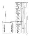
- FIG. 7 is a block diagram showing the Interrupt Descriptor Table
- FIG. 8 is a block diagram showing remote software loading
- FIG. 9 is a flow diagram showing a method of creating and initializing an MCP software environment.
- the Network Services Processor (NSP) 110 role is to provide the database and coordination control of the soft-switch. This is where the global feature definitions are controlled. It performs loading of necessary data to the Media Control Platforms (MCP) 150 , 160 and 170 and also performs those coordinated functions necessary to keep the system running (e.g., maintenance, recovery, administration, alarming, etc).
- MCP Media Control Platforms
- the Inter-Connect Controller (ICC), 120 is a multifunctional unit. It provides a bi-directional interface between the NSP and the distributed MCPs. It also supervises the LAN (Ethernet, as an example) interfaces (not shown) and performs inter-platform message routing.
- ICC Inter-Connect Controller
- the Integrated Signaling Gateway, 130 performs the signaling gateway function. It terminates Number Seven Signaling (SS7) or Stream Control Transmission Protocol (SCTP) signaling messages from an external network and converts them into internal messages.
- SS7 Number Seven Signaling
- SCTP Stream Control Transmission Protocol
- the packet manager (PM), 140 provides, as one of its functions, the interface to the Media Gateways (MG).
- Media Gateways are connected to end-offices (EO) and contain real trunks, usually TDM trunks (or may be virtual Asynchronous Transfer Mode (ATM) paths).
- TDM trunks or may be virtual Asynchronous Transfer Mode (ATM) paths.
- Each MG trunk connected to TDM circuits has a physical appearance on the Media Gateway as a DS0 channel (within a T1 or DS3).
- Each MG trunk is assigned a dedicated virtual MCT port. MCTs can control and refer to these trunks as needed for call processing.
- a soft-switch can support many thousands of trunks.
- the Media Control Platform (MCP), 150 , 160 , and 170 consists of a slot based CPU (e.g., Pentium III or IV 500 mhz or better) in a backplane.
- the MCP provides a platform for media control functions, which work with the software in the NSP to provide media control features.
- Many MCPs may exist in a soft-switch environment.
- an MCP software environment, 200 contains several functional parts.
- the first part is a MCP Manager, 220 , comprising a Messaging Task, 250 , a SW Watchdog task, 240 , a MCT Loading and Startup Task, 230 , and a MCP Maintenance Task, 260 .
- Another is Media Control functions comprising the LTG tasks (i.e., MCT tasks) 291 , 292 , and 293 , and the LAN (Ethernet) connectivity interface, 210 .
- the entire software environment is controlled by an operating system such as the commercial VxWorks product which runs under the microprocessor and associated memory.
- the Messaging Task, 250 is a multi-functional task providing the interface to the Ethernet for communications between all tasks on the MCP and the NCP or other distributed platforms. It also provides an interface with the ICC, 120 , for maintenance of the LAN and the message channels associated with the MCTs.
- the MCT Loading and Startup Task, 230 provides an interface to the NSP for loading of MCT software. It is also responsible for managing and manipulating the context associated with each MCT, and for spawning each MCT task in its correct context.
- the MCP Maintenance Task, 260 performs general maintenance functions on the MCP, including handling reset requests from the NSP and for performing firmware and software upgrades as well as MCT code patching.
- the SW Watchdog Task, 240 is responsible for monitoring all MCP and MCT tasks to ensure each task is running correctly.
- the LTG tasks also known as MCT tasks, 291 , 292 , and 293 contain the adapted legacy software logic to provide a plethora of telecommunications call control features.
- MCT tasks also known as MCT tasks, 291 , 292 , and 293 contain the adapted legacy software logic to provide a plethora of telecommunications call control features.
- TABLE A summarizes legacy features that are provided by the LTG software are generally known to one skilled in the art and known in the industry. This is the software functionality that has been preserved and reused by the MCT software to provide the same feature functionality in a packet based soft-switch. These features include but not limited to:
- the commercial platform, 300 used to embody the MCP is shown. It can be a compact Peripheral Component Interconnect (PCI) board or other suitable microprocessor platform.
- the processor can be a processor such as an Intel Pentium III, 310 , running at 500 mhz or higher.
- the board will contain a typical Pentium compliant basic input/output system (BIOS), 320 , an Internet Protocol Stack (IP Stack), 350 , for buffering and controlling packet messages and a VxWorks or equivalent board support package, 330 , which is processor and hardware specific support such as drivers, or specific Ethernet stack.
- BIOS basic input/output system
- IP Stack Internet Protocol Stack
- VxWorks or equivalent board support package 330
- the OS itself, 370 , controls the real-time operation of the software on the processor, 310 .
- the OS can be one of many commercial products such as Linux or VxWorks.
- Adaptation layer, 340 are hardware specific adaptions to support flash disks and Ethernet cards.
- Adaptation layer, 360 is a specific inventive element that provides a software abstraction and adaptation concerning SW context switching and interrupt service routines (ISR). This inventive aspect will be discussed more below.
- ISR SW context switching and interrupt service routines
- the MCT loading and startup task, 230 is one of the software adaptations of this invention that mimics the legacy firmware and recovery software to receive (download) one single copy of the legacy software from a remote coordination processor (e.g., NSP) and then spawns as many as sixty-four legacy incarnations or instances, which share the same code space but have their own data memory areas.
- the remote coordination processor e.g., NSP
- the remote coordination processor is not aware of the SW adaptation layer, thinking that it communicates with sixty-four individual legacy platforms. Each of the sixty-four incarnations thinks that they run under their own native environment.
- the illustrative MCT instances, 370 and 375 are two of sixty-four possible instances of the legacy LTG software. More are possible in other embodiments.
- This software is typically sixteen-bit assembly code legacy operating system and switching application software with one copy per hardware platform. Now with these inventive adaptation layers, as many as sixty-four copies of the legacy software runs on one commercial platform.
- legacy code image, 445 originating from the NSP, 110 , is sent to the Messaging Task, 250 , using a internal message, 410 .
- the code image arrives through the IP Stack, 350 , and is forwarded to the Loading and Startup Task, 230 .
- the MCT Loading and Startup task also creates the contexts of each MCT tasks 0–63 as shown by expansion block 480 .
- the Context_table_(CTX) array (CTX array), 480 contains a Global Descriptor Table (GDT) which describes the memory assigned to each MCT task. This memory must be unique to each task with no overlap. It is calculated by adding data and stack segments of the original legacy GDT, which is embedded in the legacy code image.
- GDT Global Descriptor Table
- the CTX array provides the storage space for the central processing unit (CPU) registers, such as CS (Code Segment), DS (Data Segment), ES, FS, and GS (additional code segments), SS (Stack Segment), DR0-7 registers, which are altered by the commercial OS during interrupt handling and tasks context switching.
- CPU central processing unit
- FIG. 5 shows in more detail the structure of an exemplary GDT, 600 .
- the sections of the GDT include a space for the OS to operate within, 502 , configuration data, 504 , interface GDT, 510 , and transient data for processing, 506 .
- the contents of the interface GDT, 510 are exploded which is a part of the present invention's adaptation.
- This interface GDT provides the steering mechanism to the location of essential entry address points into the legacy LTG software logic and data.
- the contents of the interface GDT is representative, but reflect the essential linking addresses of routines and logic in the MCT software. These are typically state-driven software entry addresses, data memory addresses and constants. Registers are also initialized.
- the NSP sends a bitmap, 490 , to the MCP as shown in FIG. 4A .
- the Loading & Startup task eventually starts the corresponding MCT task.
- the MCT tasks are able to receive configuration and subscriber data directly from the NSP and eventually begin processing traffic.
- the Loading and Startup task, 230 calculates the size of the individual data of each legacy task. It then allocates the memory for each task and stores their addresses, shown as 492 , in the task context table, 600 .
- a context switching routine, 605 uses this table to assign the right memory space to the next task, shown as 493 (corresponds to MCT task 370 ) and 494 (corresponding to MCT task 375 ).
- Each of the MCT tasks that has been started by the Loading and Startup Task receives control of the processor when the VxWorks OS schedules a MCT a task. This is done on a regular interval such as a 1-millisecond rate.
- VxWorks calls an adaptation routine illustratively named Context-Switch, 605 , as shown in FIG. 6 .
- Context-Switch provides to Context-Switch as input (shown as 608 ) the current task (n ⁇ 1) to be suspended and the next task (n) to be started. This Context-Switch swaps out the current task with the next task. This is based upon the bitmap, 490 ( FIG. 4A ).
- Context-Switch accesses shown as 610 , a Context-Table (CTX) array, 600 , saves the processor state, 640 , of task n ⁇ 1 as shown by the data flow arrow, 620 , in the proper array location associated with task n ⁇ 1.
- the next task n has its processor state restored as shown by data flow arrow, 630 .
- Actual transfer of processor control follows this processor state restoration to the MCT address restored, which could be any one of the 64 MCT tasks such as 370 .
- a MCT task runs as if it were in a legacy environment, believing it is the only task running in the system as it was in a legacy environment. It will be interrupted when the next 1 ms-timer tick occurs and the OS repeats the Context-Switch swap operation.
- FIG. 7 another adaptation for this present invention is shown.
- the usual interrupt service routine (ISR) of the VxWorks OS, 370 is replaced by “shell ISRs”.
- ISR interrupt service routine
- shell ISRs Using an Interrupt Descriptor Table, 705 , a VxWorks interrupt or exception is translated to a “shell ISR”.
- a “shell ISR” has two functions. In the case of interrupts, it saves all the CPU registers of the interrupted task and restores the CPU OS default registers before invoking of the OS original ISR.
- a shell function checks if the current task is a “MCP-task” (i.e., VxWorks task, 32 bit code) or a “MCT task” (i.e., 16 bit legacy code). If a MCP task, the original VxWorks ISR is invoked. Otherwise, the legacy ISR is invoked.
- MCP-task i.e., VxWorks task, 32 bit code
- MCT task i.e
- the default VxWorks stack fault exception handler first determines whether the fault occurred within a MCT or in the general VxWorks context (kernel or other MCP tasks). If the fault occurred in the general VxWorks context, then the platform is restarted since this represents a non-recoverable error. However, if the fault occurred in a MCT, then the task state of the MCT is modified so that it resumes execution at the existing stack fault recovery software within the MCT. The exception handler also rebuilds the MCT stack so that it can resume operations correctly. Each MCT is responsible for handling its own exceptions.
- the MCTs also needs to interface to certain VxWorks services. Since MCTs operate in 16-bit mode and are separately linked, this interface cannot be implemented via a direct call. Instead an indirect reference interface is used through “call gates”. On activation of the MCTs, a reserved descriptor entry in the GDT is configured to represent a call gate. When the MCT invokes this call gate, it is redirected to execute a procedure within the VxWorks image, whose address has been populated in the call gate descriptor. A translation from 16-bit to 32-bit also occurs. This is another mixed-mode adaptation of this present invention.
- a MCP platform, 150 powers up or resets, the MCP software environment is created and initialized.
- the boot process of a MCP retrieves via File Transfer Protocol (FTP) the VxWorks and MCP application (e.g., the adaptation layer) image from a remote server, 820 , and step 905 .
- This server can be anywhere on the local or remote LAN, 840 .
- the soft-switch is located behind a firewall & router, 810 , and this FTP transfer may traverse the firewall, which is connected with the packet manager of the soft-switch, 140 .
- a Media Gateway, 815 which interfaces the soft-switch to operating companies. It is conceivable that the FTP download would traverse this path.
- the OS runs and spawns the MCP tasks, step 910 .
- a craftsperson enters a command at the NSP, 110 , to initiate MCP legacy code (e.g., MCT code images) loading, step 915 .
- MCP legacy code e.g., MCT code images
- This code is stored typically on a NSP disk, 805 .
- the legacy code is loaded into the MCPs, step 915 , the MCT code image is initiated and call processing is subsequently initiated, step 925 .
- this invention permits the reuse of TDM legacy software in a packet based soft-switch.
- An adaptation SW layer serves to isolate a legacy SW, known as MCT, from the commercial OS such as VxWorks.
- the legacy SW and the OS (and supporting functions) for example, is 16-bit and 32-bit SW respectively.
- the legacy SW is loaded and started by an adaptation, which calculates and creates a context memory area of each MCT appropriate to each image, step 920 .
- the loading and startup task creates these context memory areas based on the original legacy GDT embedded in the legacy code received from a NSP.
- This context area includes memory sizing boundary information for each MCT working area, interface GDT for each MCT, transient data for each MCT, and configuration data area of for MCT.
- the configuration data configures call processing features.
- the MCTs (call processing) are started by the adaptation layer according to a bitmap received from the NSP.
- the context area also contains memory allocations for all call processing features for each MCT.
- the GDT of each MCT context area contains address and mapping information of the location of all MCT software entries for each instance of MCT.
- the context area also contains memory space for real-time processor task context storage for each MCT.
- the OS creates regular time slices, shown as step 930 , for the MCP tasks and MCT tasks and provides current and next task input to an adaptation software layer (such as Context-Switch), step 940 , the adaptation layer accesses appropriate GDT areas swapping out the current task processor environment and swapping in the next tasks processor environment, step 945 .
- an adaptation software layer such as Context-Switch
- an adaptation layer shell ISR services interrupts, step 950 .
- This adaptation layer shell ISR checks if the interrupt is for a 16-bit software current task or for a 32-bit current software task and passes control to the proper ISR using appropriate call linkages according to the target ISR, either an MCP or MCT ISR, step 955 .
- This method continues at step 940 The method restarts on a power reset or fatal MCP error at step 900 .
Abstract
Description
| TABLE A | |
| LINE FEATURES | TANDEM FEATURES |
| Three Way Calling | Tandem Office Capability Feature |
| Centrex Call Forwarding | Limited Local Tandem Switching |
| Centrex Call Origination | Local Inter-Tandem Switching |
| Restrictions | 900 Service Access - Split |
| Centrex Call Termination | Routing |
| Restrictions | LNP Enhancements for Access |
| Centrex Dialing Plan | Tandem Offices |
| Centrex Private Facilities | LNP Network Management |
| Code Restriction | Enhancements |
| Customer Originated Trace | Network Management |
| Denied Origination | Surveillance data - Processor |
| Centrex Announcements | Occupancy |
| Call Hold | Two-Way Tandem Connecting |
| Intercom Dialing | Trunks (Not Coded) |
| Call Forwarding (IAD PBX) | Primary Intertandem (IT) |
| Call Waiting (IAD PBX) | Connecting Trunks |
| MLHG Queuing | 800 Service Trunks |
| MLHG Update Capability | Access Tandem Call Processing |
| Message Rate Service Area | Trunk-to-Trunk Test |
| OUTWATS | Connections |
| Selective Call Acceptance | 3-Digit Translation |
| Selective Call Forwarding | NXX Office and Special Purpose |
| Selective Call Rejection | Codes |
| Simulated Facility Groups | NXX Area Codes |
| Speed Calling | 6-digit Translation |
| Call Pickup Features | Digit Deletion |
| Centrex Call Transfer Variations | Digit Prefixing |
| Outgoing Facility Group Queuing | Code Conversion |
| Call Transfer | Route Advance Logic |
| Calling Name Delivery | Trunk Class Screening |
| Equal Access to Interexchange | Common Channel Signaling |
| Carriers | Multiple Trunk Test Capability |
| Local Number Portability | Two-Way Trunk Maintenance |
| CALEA | Trunk Group Controls |
| AIN Triggers | Network Management |
| Call Forwarding (inter-IAD) | Surveillance Data |
| Assume Dial “9” | Centralized Network Management |
| Automatic Facility Routing | NM Audits and Alerts |
| Automatic Route Selection | Message Administration |
| Call Waiting Originating | Backup Network Management |
| Calling Number Delivery | Capabilities |
| CAT Codes | Access Tandem AMA |
| Centrex Attendant Codes | 800 Service Function - |
| Denied Termination | Originating Screening Office |
| Do Not Disturb/Advanced DND | Traffic Measurements (Tandem) |
| Facility Restriction Level | Maintenance Measurements |
| Flat Rate Service Area | (Tandem) |
| Intercom Dialing | Access Tandem Traffic and |
| INWATS | Maintenance Measurements |
| MLHG Forced Announcement | Separate Routing of NPA - |
| MLHG Hunt Busy Limit | Directory Assistance Calls |
| MLHG Hunting Algorithms | Store and Forward AMATPS |
| Stop Hunt | Teleprocessing Capability |
| Terminal Make Busy | 900 Service Access |
| Toll Restriction/Enhanced Toll | CCS Exchange Access Interface |
| Restriction | AMA 56 Kbps Data Link |
| Unidentified Call Rejection | Software Carrier Group Alarm |
| Voice Assisted Dialing | EADAS/NM Interface |
| Voice Mail Service | EADAS Interface |
| Automatic Callback | RMAS Interface |
| Automatic Recall | Number 2 Switching Control |
| Call Park | Center System (SCCS) Interface |
| Operations System Standard | |
| Interface | |
| Trunk Group Circular Hunt | |
Claims (17)
Priority Applications (1)
| Application Number | Priority Date | Filing Date | Title |
|---|---|---|---|
| US10/109,196 US7079531B2 (en) | 2001-03-28 | 2002-03-28 | Method and apparatus for providing a software adaption layer in a telecommunications system |
Applications Claiming Priority (3)
| Application Number | Priority Date | Filing Date | Title |
|---|---|---|---|
| US27929501P | 2001-03-28 | 2001-03-28 | |
| US27927901P | 2001-03-28 | 2001-03-28 | |
| US10/109,196 US7079531B2 (en) | 2001-03-28 | 2002-03-28 | Method and apparatus for providing a software adaption layer in a telecommunications system |
Publications (2)
| Publication Number | Publication Date |
|---|---|
| US20020186712A1 US20020186712A1 (en) | 2002-12-12 |
| US7079531B2 true US7079531B2 (en) | 2006-07-18 |
Family
ID=27380617
Family Applications (1)
| Application Number | Title | Priority Date | Filing Date |
|---|---|---|---|
| US10/109,196 Active 2024-12-17 US7079531B2 (en) | 2001-03-28 | 2002-03-28 | Method and apparatus for providing a software adaption layer in a telecommunications system |
Country Status (1)
| Country | Link |
|---|---|
| US (1) | US7079531B2 (en) |
Cited By (3)
| Publication number | Priority date | Publication date | Assignee | Title |
|---|---|---|---|---|
| US20070022421A1 (en) * | 2003-04-09 | 2007-01-25 | Eric Lescouet | Operating systems |
| US7779098B1 (en) | 2005-12-20 | 2010-08-17 | At&T Intellectual Property Ii, L.P. | Methods for identifying and recovering stranded and access-no-revenue network circuits |
| US8307057B1 (en) | 2005-12-20 | 2012-11-06 | At&T Intellectual Property Ii, L.P. | Methods for identifying and recovering non-revenue generating network circuits established outside of the united states |
Citations (3)
| Publication number | Priority date | Publication date | Assignee | Title |
|---|---|---|---|---|
| US20020102999A1 (en) * | 2000-03-03 | 2002-08-01 | Qualcomm, Inc. | Method and apparatus for enabling group communication services in an existing communication system |
| US20020120760A1 (en) * | 2000-05-26 | 2002-08-29 | Gur Kimchi | Communications protocol |
| US6760324B1 (en) * | 1999-09-10 | 2004-07-06 | Array Telecom Corporation | Method, system, and computer program product for providing voice over the internet communication |
-
2002
- 2002-03-28 US US10/109,196 patent/US7079531B2/en active Active
Patent Citations (3)
| Publication number | Priority date | Publication date | Assignee | Title |
|---|---|---|---|---|
| US6760324B1 (en) * | 1999-09-10 | 2004-07-06 | Array Telecom Corporation | Method, system, and computer program product for providing voice over the internet communication |
| US20020102999A1 (en) * | 2000-03-03 | 2002-08-01 | Qualcomm, Inc. | Method and apparatus for enabling group communication services in an existing communication system |
| US20020120760A1 (en) * | 2000-05-26 | 2002-08-29 | Gur Kimchi | Communications protocol |
Cited By (5)
| Publication number | Priority date | Publication date | Assignee | Title |
|---|---|---|---|---|
| US20070022421A1 (en) * | 2003-04-09 | 2007-01-25 | Eric Lescouet | Operating systems |
| US8201170B2 (en) * | 2003-04-09 | 2012-06-12 | Jaluna Sa | Operating systems are executed on common program and interrupt service routine of low priority OS is modified to response to interrupts from common program only |
| US7779098B1 (en) | 2005-12-20 | 2010-08-17 | At&T Intellectual Property Ii, L.P. | Methods for identifying and recovering stranded and access-no-revenue network circuits |
| US8307057B1 (en) | 2005-12-20 | 2012-11-06 | At&T Intellectual Property Ii, L.P. | Methods for identifying and recovering non-revenue generating network circuits established outside of the united states |
| US8661110B2 (en) | 2005-12-20 | 2014-02-25 | At&T Intellectual Property Ii, L.P. | Methods for identifying and recovering non-revenue generating network circuits established outside of the United States |
Also Published As
| Publication number | Publication date |
|---|---|
| US20020186712A1 (en) | 2002-12-12 |
Similar Documents
| Publication | Publication Date | Title |
|---|---|---|
| US4993017A (en) | Modularly structured ISDN communication system | |
| US20020154646A1 (en) | Programmable network services node | |
| US7320017B1 (en) | Media gateway adapter | |
| US7095747B2 (en) | Method and apparatus for a messaging protocol within a distributed telecommunications architecture | |
| US7568125B2 (en) | Data replication for redundant network components | |
| US7702090B1 (en) | Processing a subscriber call in a telecommunications network | |
| US7529269B1 (en) | Communicating messages in a multiple communication protocol network | |
| US20040133624A1 (en) | Method and apparatus for performing common call processing management using common software platform | |
| USH1881H (en) | System and method for forming circuit connections within a telecommunications switching platform | |
| US20050117563A1 (en) | Method for linking units with standardized interfaces to devices of a network system | |
| US20020188713A1 (en) | Distributed architecture for a telecommunications system | |
| US5664010A (en) | System and method for providing an improved telecommunications service node | |
| WO1998009419A1 (en) | Telecommunications control system and method | |
| US6594685B1 (en) | Universal application programming interface having generic message format | |
| USH1860H (en) | Fault testing in a telecommunications switching platform | |
| KR20040062849A (en) | Apparatus for N:1 Redundancy of voice processing unit in media gateway system and method thereof | |
| US7079531B2 (en) | Method and apparatus for providing a software adaption layer in a telecommunications system | |
| US6920143B1 (en) | Computer telephony system using multiple hardware platforms to provide telephony services | |
| US8054947B2 (en) | Apparatus and method for multiplexing communication signals | |
| USH1940H1 (en) | System and method for dynamically mapping components within a telecommunications switching platform | |
| USH1801H (en) | Switching module for a telecommunications switching platform | |
| US8086894B1 (en) | Managing redundant network components | |
| US7218723B2 (en) | Next-generation network that reduces the effect of a service failure | |
| WO1999033278A2 (en) | Interface components for a telecommunications switching platform | |
| EP0592153A2 (en) | Telecommunications system with redundant SS7 signaling interfaces |
Legal Events
| Date | Code | Title | Description |
|---|---|---|---|
| AS | Assignment |
Owner name: SIEMENS INFORMATION AND COMMUNICATION NETWORKS, IN Free format text: ASSIGNMENT OF ASSIGNORS INTEREST;ASSIGNORS:DINH, LE VAN;LAXMAN, AMRUTH;SARMIENTO, JESUS L.;REEL/FRAME:012899/0186;SIGNING DATES FROM 20020429 TO 20020503 |
|
| FEPP | Fee payment procedure |
Free format text: PAYOR NUMBER ASSIGNED (ORIGINAL EVENT CODE: ASPN); ENTITY STATUS OF PATENT OWNER: LARGE ENTITY |
|
| AS | Assignment |
Owner name: SIEMENS COMMUNICATIONS, INC., FLORIDA Free format text: MERGER;ASSIGNOR:SIEMENS INFORMATION AND COMMUNICATION NETWORKS, INC.;REEL/FRAME:017434/0435 Effective date: 20041001 |
|
| STCF | Information on status: patent grant |
Free format text: PATENTED CASE |
|
| AS | Assignment |
Owner name: NOKIA SIEMENS NETWORKS GMBH & CO. KG, GERMANY Free format text: ASSIGNMENT OF ASSIGNORS INTEREST;ASSIGNOR:SIEMENS COMMUNICATIONS, INC.;REEL/FRAME:020773/0310 Effective date: 20080313 |
|
| FPAY | Fee payment |
Year of fee payment: 4 |
|
| FPAY | Fee payment |
Year of fee payment: 8 |
|
| AS | Assignment |
Owner name: NOKIA SOLUTIONS AND NETWORKS US LLC, TEXAS Free format text: ASSIGNMENT OF ASSIGNORS INTEREST;ASSIGNOR:NOKIA SOLUTIONS AND NETWORKS GMBH & CO. KG (FORMERLY KNOWN AS NOKIA SIEMENS NETWORKS GMBH & CO. KG);REEL/FRAME:033739/0987 Effective date: 20140909 |
|
| AS | Assignment |
Owner name: NOKIA SOLUTIONS AND NETWORKS GMBH & CO. KG, GERMANY Free format text: CHANGE OF NAME;ASSIGNOR:NOKIA SIEMENS NETWORKS GMBH & CO. KG;REEL/FRAME:034294/0675 Effective date: 20130912 Owner name: NOKIA SOLUTIONS AND NETWORKS GMBH & CO. KG, GERMAN Free format text: CHANGE OF NAME;ASSIGNOR:NOKIA SIEMENS NETWORKS GMBH & CO. KG;REEL/FRAME:034294/0675 Effective date: 20130912 |
|
| MAFP | Maintenance fee payment |
Free format text: PAYMENT OF MAINTENANCE FEE, 12TH YEAR, LARGE ENTITY (ORIGINAL EVENT CODE: M1553) Year of fee payment: 12 |