US7069997B2 - Valve cage insert - Google Patents
Valve cage insert Download PDFInfo
- Publication number
- US7069997B2 US7069997B2 US10/624,235 US62423503A US7069997B2 US 7069997 B2 US7069997 B2 US 7069997B2 US 62423503 A US62423503 A US 62423503A US 7069997 B2 US7069997 B2 US 7069997B2
- Authority
- US
- United States
- Prior art keywords
- flanges
- insert
- ribs
- set forth
- ball
- Prior art date
- Legal status (The legal status is an assumption and is not a legal conclusion. Google has not performed a legal analysis and makes no representation as to the accuracy of the status listed.)
- Expired - Lifetime
Links
- 230000003014 reinforcing effect Effects 0.000 claims abstract description 8
- 238000007493 shaping process Methods 0.000 claims 1
- 239000012530 fluid Substances 0.000 abstract description 12
- 230000001737 promoting effect Effects 0.000 abstract description 2
- 230000002787 reinforcement Effects 0.000 abstract description 2
- 125000006850 spacer group Chemical group 0.000 description 3
- 229910000831 Steel Inorganic materials 0.000 description 1
- 239000000956 alloy Substances 0.000 description 1
- 229910045601 alloy Inorganic materials 0.000 description 1
- 230000015572 biosynthetic process Effects 0.000 description 1
- 230000000694 effects Effects 0.000 description 1
- 230000004048 modification Effects 0.000 description 1
- 238000012986 modification Methods 0.000 description 1
- 230000000452 restraining effect Effects 0.000 description 1
- 230000000717 retained effect Effects 0.000 description 1
- 239000010959 steel Substances 0.000 description 1
Images


Classifications
-
- E—FIXED CONSTRUCTIONS
- E21—EARTH DRILLING; MINING
- E21B—EARTH DRILLING, e.g. DEEP DRILLING; OBTAINING OIL, GAS, WATER, SOLUBLE OR MELTABLE MATERIALS OR A SLURRY OF MINERALS FROM WELLS
- E21B34/00—Valve arrangements for boreholes or wells
- E21B34/06—Valve arrangements for boreholes or wells in wells
- E21B34/08—Valve arrangements for boreholes or wells in wells responsive to flow or pressure of the fluid obtained
-
- F—MECHANICAL ENGINEERING; LIGHTING; HEATING; WEAPONS; BLASTING
- F04—POSITIVE - DISPLACEMENT MACHINES FOR LIQUIDS; PUMPS FOR LIQUIDS OR ELASTIC FLUIDS
- F04B—POSITIVE-DISPLACEMENT MACHINES FOR LIQUIDS; PUMPS
- F04B47/00—Pumps or pumping installations specially adapted for raising fluids from great depths, e.g. well pumps
- F04B47/02—Pumps or pumping installations specially adapted for raising fluids from great depths, e.g. well pumps the driving mechanisms being situated at ground level
-
- F—MECHANICAL ENGINEERING; LIGHTING; HEATING; WEAPONS; BLASTING
- F04—POSITIVE - DISPLACEMENT MACHINES FOR LIQUIDS; PUMPS FOR LIQUIDS OR ELASTIC FLUIDS
- F04B—POSITIVE-DISPLACEMENT MACHINES FOR LIQUIDS; PUMPS
- F04B53/00—Component parts, details or accessories not provided for in, or of interest apart from, groups F04B1/00 - F04B23/00 or F04B39/00 - F04B47/00
- F04B53/10—Valves; Arrangement of valves
- F04B53/1002—Ball valves
- F04B53/1007—Ball valves having means for guiding the closure member
-
- F—MECHANICAL ENGINEERING; LIGHTING; HEATING; WEAPONS; BLASTING
- F16—ENGINEERING ELEMENTS AND UNITS; GENERAL MEASURES FOR PRODUCING AND MAINTAINING EFFECTIVE FUNCTIONING OF MACHINES OR INSTALLATIONS; THERMAL INSULATION IN GENERAL
- F16K—VALVES; TAPS; COCKS; ACTUATING-FLOATS; DEVICES FOR VENTING OR AERATING
- F16K15/00—Check valves
- F16K15/02—Check valves with guided rigid valve members
- F16K15/04—Check valves with guided rigid valve members shaped as balls
-
- F—MECHANICAL ENGINEERING; LIGHTING; HEATING; WEAPONS; BLASTING
- F16—ENGINEERING ELEMENTS AND UNITS; GENERAL MEASURES FOR PRODUCING AND MAINTAINING EFFECTIVE FUNCTIONING OF MACHINES OR INSTALLATIONS; THERMAL INSULATION IN GENERAL
- F16K—VALVES; TAPS; COCKS; ACTUATING-FLOATS; DEVICES FOR VENTING OR AERATING
- F16K27/00—Construction of housing; Use of materials therefor
- F16K27/02—Construction of housing; Use of materials therefor of lift valves
- F16K27/0209—Check valves or pivoted valves
-
- F—MECHANICAL ENGINEERING; LIGHTING; HEATING; WEAPONS; BLASTING
- F16—ENGINEERING ELEMENTS AND UNITS; GENERAL MEASURES FOR PRODUCING AND MAINTAINING EFFECTIVE FUNCTIONING OF MACHINES OR INSTALLATIONS; THERMAL INSULATION IN GENERAL
- F16K—VALVES; TAPS; COCKS; ACTUATING-FLOATS; DEVICES FOR VENTING OR AERATING
- F16K2200/00—Details of valves
- F16K2200/50—Self-contained valve assemblies
- F16K2200/502—Cages for valves, i.e. means to be inserted within the valve housing, surrounding and guiding the closure member
-
- Y—GENERAL TAGGING OF NEW TECHNOLOGICAL DEVELOPMENTS; GENERAL TAGGING OF CROSS-SECTIONAL TECHNOLOGIES SPANNING OVER SEVERAL SECTIONS OF THE IPC; TECHNICAL SUBJECTS COVERED BY FORMER USPC CROSS-REFERENCE ART COLLECTIONS [XRACs] AND DIGESTS
- Y10—TECHNICAL SUBJECTS COVERED BY FORMER USPC
- Y10T—TECHNICAL SUBJECTS COVERED BY FORMER US CLASSIFICATION
- Y10T137/00—Fluid handling
- Y10T137/7722—Line condition change responsive valves
- Y10T137/7837—Direct response valves [i.e., check valve type]
- Y10T137/7904—Reciprocating valves
- Y10T137/7908—Weight biased
- Y10T137/7909—Valve body is the weight
- Y10T137/791—Ball valves
Definitions
- Reciprocating, sucker rod-driven, downhole pumps are commonly used in wells to raise produced fluid to ground surface from a subsurface formation.
- This type of pump usually incorporates a pair of ball and seat valves in its plunger. These valves are referred to as the standing and travelling valves.
- these valves comprise:
- the ‘cage’ in the form of an external, tubular, cylindrical ‘shell’ and an internal, slidingly received ‘insert’.
- the insert is formed of hard alloy.
- a typical prior art shell/insert assembly is shown in FIG. 1 .
- the shell/insert assembly comprises:
- the present invention is concerned with providing a modified insert which is designed with a view to improving volumetric flow.
- the invention also seeks to incorporate desirable flow pattern and pressure drop characteristics.
- an insert in which the ball guide flanges thin in cross-section as they extend inwardly and upwardly from the ribs.
- the inner upper ends of the flanges are connected with and tied together by an elongate, upwardly extending reinforcing member protruding above the top ring.
- the ribs are arranged to define helically directed side openings and the flanges are also helically configured.
- the incoming fluid is induced to adopt a helical flow pattern as it moves through the insert, thereby creating a centrifugal effect.
- FIG. 1 is a sectional side view showing a shell/insert assembly in accordance with the prior art—the insert is shown positioned in the shell with a ball in the insert bore—the insert is retained in place by a seat and spacer;
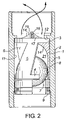
- FIG. 2 is a partially sectional side view showing a shell/insert assembly in accordance with the present invention
- FIG. 3 is a side view of the insert of FIG. 2 ;
- FIG. 4 is a top view of the insert
- FIG. 5 is a bottom view of the insert
- FIG. 6 is a perspective view of the insert
- FIG. 7 is a perspective view of the insert with an unseated ball in place.
- FIG. 8 is a perspective view similar to FIG. 7 , showing the ball in contact with the stop.
- the insert 1 is a tubular, cylindrical body adapted for use in the shell 2 of an insert-type ball and seat valve.
- the insert 1 comprises horizontal, vertically spaced apart top and bottom rings 3 , 4 .
- the rings are connected together by circumferentially spaced apart ribs 5 .
- the ribs 5 and rings 3 , 4 combine to form side openings 6 .
- the shell 2 supports an inwardly protruding, annular seat 7 , against which the valve ball 8 seats and seals.
- a bottom spacer 9 supports and locks the bottom end of the seat 7 in place in the bore 11 of the shell 2 .
- a shoulder 12 of the shell 2 locks the insert body 1 in place at its upper end.
- the ribs 5 are inclined and shaped so that side openings 6 are helically configured.
- the ribs 5 support integral, inwardly extending, helically directed flanges 14 .
- the flanges 14 are each shown as thinning along their length. They arch inwardly and come together at the insert's longitudinal axis.
- the flanges 14 and top ring 3 combine to form top outlets 24 .
- the upper inner ends 15 of the flanges 14 are integral with and connected to an upwardly directed, elongate, rod-like reinforcing member 16 .
- the reinforcing member 16 has a length greater than the vertical thicknesses of the flanges' upper inner ends 15 and protrudes above the upper rim 17 of the top ring 3 .
- the bottom surfaces 18 , 19 of the flanges 14 and reinforcing member 16 are formed so as to provide a smooth semi-spherical stop surface 20 for engaging and restraining upward movement of the ball 8 .
- the stop surface 20 is located beneath the upper edge of the top ring 3 .
- the insert in use, is positioned in the bore 11 of the shell 2 .
- a valve ball 8 is provided within the insert bore 21 .
- the valve ball 8 can seat on the annular seat 7 to close the insert bore 21 , or it can be displaced upwardly by fluid pressure from below.
- fluid flows upwardly through the channels 22 between the flanges 14 and outwardly around the ball 8 by moving through the passageways 23 provided by the side openings 6 .
- the fluid is caused to swirl as it follows the helically oriented flow paths.
- the fluid exits through the top outlets 24 .
Abstract
Description
-
- a vertically oriented, cylindrical, tubular cage forming a through-bore and having internal ball guide flanges;
- a horizontal annular seat extending across the bore at its lower end——the seat is supported by the cage;
- a ball positioned within the cage bore; and
- a transverse ball stop extending across the upper end of the bore and connected with the cage wall;
whereby the ball can seat on the seat to close the bore or may be unseated by pressure from below to permit fluid to pass upwardly a round the ball and between the guide flanges. The fluid exits through top outlets formed between the ball stop crossbars and the cage side wall.
-
- An external steel shell, which has an internal stop shoulder for locking in the insert at the upper end and which supports and contains separate annular seat and sealed spacer members at its lower end; and
- An insert which comprises horizontal top and bottom rings joined by vertical, circumferentially spaced apart ribs forming side openings or “windows” between them. The ribs support inwardly projecting ball guide flanges arching inwardly to form a semi-spherical ball stop for retaining the valve ball. The side openings provide passageways for fluid flow around the ball. The flanges and top ring further form top outlets for egress of the fluid from the upper end of the inset.
-
- thinning of the flanges leads to increasing the open area of the top outlets, thereby promoting the volumetric fluid capacity of the valve; and
- the reinforcement member provides structural strength to reinforce the thinned flanges so as to better resist the upward impacts delivered by the ball.
Claims (8)
Priority Applications (1)
| Application Number | Priority Date | Filing Date | Title |
|---|---|---|---|
| US10/624,235 US7069997B2 (en) | 2002-07-22 | 2003-07-21 | Valve cage insert |
Applications Claiming Priority (2)
| Application Number | Priority Date | Filing Date | Title |
|---|---|---|---|
| US39701502P | 2002-07-22 | 2002-07-22 | |
| US10/624,235 US7069997B2 (en) | 2002-07-22 | 2003-07-21 | Valve cage insert |
Publications (2)
| Publication Number | Publication Date |
|---|---|
| US20050257927A1 US20050257927A1 (en) | 2005-11-24 |
| US7069997B2 true US7069997B2 (en) | 2006-07-04 |
Family
ID=31188373
Family Applications (1)
| Application Number | Title | Priority Date | Filing Date |
|---|---|---|---|
| US10/624,235 Expired - Lifetime US7069997B2 (en) | 2002-07-22 | 2003-07-21 | Valve cage insert |
Country Status (2)
| Country | Link |
|---|---|
| US (1) | US7069997B2 (en) |
| CA (1) | CA2435601C (en) |
Cited By (48)
| Publication number | Priority date | Publication date | Assignee | Title |
|---|---|---|---|---|
| US20060081293A1 (en) * | 2004-10-18 | 2006-04-20 | Santa Cruz Cathy D | Control valve for backwash prevention |
| US20070062706A1 (en) * | 2005-09-20 | 2007-03-22 | Leising Lawrence J | Downhole Tool Actuation Apparatus and Method |
| US20090309038A1 (en) * | 2008-05-22 | 2009-12-17 | Dr. Vladimir Balakin | Charged particle beam extraction method and apparatus used in conjunction with a charged particle cancer therapy system |
| US20100006770A1 (en) * | 2008-05-22 | 2010-01-14 | Dr. Vladimir Balakin | Charged particle beam acceleration and extraction method and apparatus used in conjunction with a charged particle cancer therapy system |
| US20100008466A1 (en) * | 2008-05-22 | 2010-01-14 | Vladimir Balakin | Charged particle cancer therapy and patient breath monitoring method and apparatus |
| US20100008468A1 (en) * | 2008-05-22 | 2010-01-14 | Vladimir Balakin | Charged particle cancer therapy x-ray method and apparatus |
| US20100128846A1 (en) * | 2008-05-22 | 2010-05-27 | Vladimir Balakin | Synchronized x-ray / breathing method and apparatus used in conjunction with a charged particle cancer therapy system |
| US20100133446A1 (en) * | 2008-05-22 | 2010-06-03 | Dr. Viadimir Balakin | Ion beam focusing lens method and apparatus used in conjunction with a charged particle cancer therapy system |
| US20100269928A1 (en) * | 2009-04-22 | 2010-10-28 | Michael Brent Ford | Valve cage for a pump |
| US20100314126A1 (en) * | 2009-06-10 | 2010-12-16 | Baker Hughes Incorporated | Seat apparatus and method |
| US20110232899A1 (en) * | 2010-03-24 | 2011-09-29 | Porter Jesse C | Composite reconfigurable tool |
| US8079413B2 (en) | 2008-12-23 | 2011-12-20 | W. Lynn Frazier | Bottom set downhole plug |
| US20120048401A1 (en) * | 2009-03-31 | 2012-03-01 | Seiji Yamashita | Ball check valve |
| CN102400904A (en) * | 2011-12-27 | 2012-04-04 | 夏东辉 | Blockage and clamping prevention large-runner oil well pump |
| USD657807S1 (en) | 2011-07-29 | 2012-04-17 | Frazier W Lynn | Configurable insert for a downhole tool |
| US8307892B2 (en) | 2009-04-21 | 2012-11-13 | Frazier W Lynn | Configurable inserts for downhole plugs |
| USD672794S1 (en) | 2011-07-29 | 2012-12-18 | Frazier W Lynn | Configurable bridge plug insert for a downhole tool |
| USD673183S1 (en) | 2011-07-29 | 2012-12-25 | Magnum Oil Tools International, Ltd. | Compact composite downhole plug |
| USD673182S1 (en) | 2011-07-29 | 2012-12-25 | Magnum Oil Tools International, Ltd. | Long range composite downhole plug |
| USD684612S1 (en) | 2011-07-29 | 2013-06-18 | W. Lynn Frazier | Configurable caged ball insert for a downhole tool |
| US8496052B2 (en) | 2008-12-23 | 2013-07-30 | Magnum Oil Tools International, Ltd. | Bottom set down hole tool |
| USD694281S1 (en) | 2011-07-29 | 2013-11-26 | W. Lynn Frazier | Lower set insert with a lower ball seat for a downhole plug |
| USD694280S1 (en) | 2011-07-29 | 2013-11-26 | W. Lynn Frazier | Configurable insert for a downhole plug |
| USD698370S1 (en) | 2011-07-29 | 2014-01-28 | W. Lynn Frazier | Lower set caged ball insert for a downhole plug |
| USD703713S1 (en) | 2011-07-29 | 2014-04-29 | W. Lynn Frazier | Configurable caged ball insert for a downhole tool |
| US8899317B2 (en) | 2008-12-23 | 2014-12-02 | W. Lynn Frazier | Decomposable pumpdown ball for downhole plugs |
| US9109428B2 (en) | 2009-04-21 | 2015-08-18 | W. Lynn Frazier | Configurable bridge plugs and methods for using same |
| US9127527B2 (en) | 2009-04-21 | 2015-09-08 | W. Lynn Frazier | Decomposable impediments for downhole tools and methods for using same |
| US9163477B2 (en) | 2009-04-21 | 2015-10-20 | W. Lynn Frazier | Configurable downhole tools and methods for using same |
| US9181772B2 (en) | 2009-04-21 | 2015-11-10 | W. Lynn Frazier | Decomposable impediments for downhole plugs |
| US9217319B2 (en) | 2012-05-18 | 2015-12-22 | Frazier Technologies, L.L.C. | High-molecular-weight polyglycolides for hydrocarbon recovery |
| USRE46028E1 (en) | 2003-05-15 | 2016-06-14 | Kureha Corporation | Method and apparatus for delayed flow or pressure change in wells |
| US9404337B1 (en) | 2012-02-22 | 2016-08-02 | McClinton Energy Group, LLC | Caged ball fractionation plug |
| US20160305409A1 (en) * | 2015-04-14 | 2016-10-20 | Michael Brent Ford | Traveling valve assembly and method therefor |
| US9506309B2 (en) | 2008-12-23 | 2016-11-29 | Frazier Ball Invention, LLC | Downhole tools having non-toxic degradable elements |
| US9562415B2 (en) | 2009-04-21 | 2017-02-07 | Magnum Oil Tools International, Ltd. | Configurable inserts for downhole plugs |
| US9587475B2 (en) | 2008-12-23 | 2017-03-07 | Frazier Ball Invention, LLC | Downhole tools having non-toxic degradable elements and their methods of use |
| US9708878B2 (en) | 2003-05-15 | 2017-07-18 | Kureha Corporation | Applications of degradable polymer for delayed mechanical changes in wells |
| WO2017160451A1 (en) * | 2016-03-18 | 2017-09-21 | Baker Hughes Incorporated | Actuation configuration and method |
| US10184314B1 (en) * | 2016-06-02 | 2019-01-22 | Black Gold Pump And Supply, Inc. | Downhole valve with cage inserts |
| US10767445B2 (en) * | 2018-05-16 | 2020-09-08 | Weatherford Technology Holdings, Llc | Valve assembly for downhole pump of reciprocating pump system |
| US20200340462A1 (en) * | 2017-10-24 | 2020-10-29 | Brose Fahrzeugteile SE & Co. Kommanditgesellschaft, Würzburg | Electromotive oil pump comprising a non-return valve |
| US11125349B1 (en) * | 2020-02-28 | 2021-09-21 | Jyothi Swaroop Samayamantula | Zero restriction ball valve insert, one-piece cage and assembly |
| US11187341B2 (en) | 2020-02-11 | 2021-11-30 | Michael Brent Ford | Drop-in insert for a valve cage of a pump |
| US11608709B2 (en) | 2020-03-31 | 2023-03-21 | Q2 Artificial Lift Services Ulc | Methods and kits for assembling a flow cage assembly for downhole reciprocating pump |
| US11913306B1 (en) | 2022-11-09 | 2024-02-27 | Ravdos Holdings Inc. | Ball cage insert with reduced wear, reduced pressure drop, and enhanced performance characteristics |
| US11913555B2 (en) | 2021-07-08 | 2024-02-27 | Q2 Artificial Lift Services Ulc | Valve assemblies and related methods for deviated wells |
| US11952866B1 (en) | 2022-09-28 | 2024-04-09 | Black Gold Pump And Supply, Inc. | Guideless cage for downhole valve |
Families Citing this family (10)
| Publication number | Priority date | Publication date | Assignee | Title |
|---|---|---|---|---|
| KR101941744B1 (en) | 2013-05-10 | 2019-01-23 | 화이트 나이트 플루이드 핸들링 인크. | Pneumatic reciprocating fluid pump with improved check valve assembly, and related methods |
| KR102508920B1 (en) * | 2015-04-29 | 2023-03-13 | 그라코 미네소타 인크. | Cartridge Style Ball Check for Positive Displacement Pumps |
| US10100609B2 (en) * | 2015-07-28 | 2018-10-16 | Michael Brent Ford | Dump valve assembly and method therefor |
| US10077629B2 (en) * | 2015-07-28 | 2018-09-18 | Michael Brent Ford | Dump valve assembly and method therefor |
| US10100829B2 (en) * | 2015-07-28 | 2018-10-16 | Michael Brent Ford | Dump valve assembly with spring and method therefor |
| US20180313453A1 (en) | 2015-11-11 | 2018-11-01 | Graco Minnesota Inc. | Compliant Check Valve for Aggregate Pump |
| US11746776B2 (en) * | 2016-05-18 | 2023-09-05 | James D. Kutella | Bi-directional bilge pump |
| US11572876B2 (en) | 2017-08-30 | 2023-02-07 | Graco Minnesota Inc. | Pump piston |
| US11091980B2 (en) * | 2018-07-03 | 2021-08-17 | Weatherford Technology Holdings, Llc | Streamlined valve assembly for downhole pump of reciprocating pump system |
| CA3121080C (en) * | 2020-06-05 | 2022-04-19 | Q2 Artificial Lift Services Ulc | Standing valve assembly and related systems for downhole reciprocating pump |
Citations (6)
| Publication number | Priority date | Publication date | Assignee | Title |
|---|---|---|---|---|
| US735248A (en) * | 1902-01-20 | 1903-08-04 | John Hahn | Pump-piston. |
| US1555068A (en) * | 1924-05-31 | 1925-09-29 | Jeddy D Nixon | Valve for pumps |
| US5117861A (en) | 1990-05-23 | 1992-06-02 | Mcconnell Kenneth R | Ball and seat-type valve for downhole rod pump |
| US5593292A (en) | 1994-05-04 | 1997-01-14 | Ivey; Ray K. | Valve cage for a rod drawn positive displacement pump |
| US6199636B1 (en) * | 1999-02-16 | 2001-03-13 | Michael L. Harrison | Open barrel cage |
| US6283148B1 (en) * | 1996-12-17 | 2001-09-04 | Flowmore Systems, Inc. | Standing valve with a curved fin |
-
2003
- 2003-07-18 CA CA002435601A patent/CA2435601C/en not_active Expired - Lifetime
- 2003-07-21 US US10/624,235 patent/US7069997B2/en not_active Expired - Lifetime
Patent Citations (6)
| Publication number | Priority date | Publication date | Assignee | Title |
|---|---|---|---|---|
| US735248A (en) * | 1902-01-20 | 1903-08-04 | John Hahn | Pump-piston. |
| US1555068A (en) * | 1924-05-31 | 1925-09-29 | Jeddy D Nixon | Valve for pumps |
| US5117861A (en) | 1990-05-23 | 1992-06-02 | Mcconnell Kenneth R | Ball and seat-type valve for downhole rod pump |
| US5593292A (en) | 1994-05-04 | 1997-01-14 | Ivey; Ray K. | Valve cage for a rod drawn positive displacement pump |
| US6283148B1 (en) * | 1996-12-17 | 2001-09-04 | Flowmore Systems, Inc. | Standing valve with a curved fin |
| US6199636B1 (en) * | 1999-02-16 | 2001-03-13 | Michael L. Harrison | Open barrel cage |
Cited By (60)
| Publication number | Priority date | Publication date | Assignee | Title |
|---|---|---|---|---|
| US10280703B2 (en) | 2003-05-15 | 2019-05-07 | Kureha Corporation | Applications of degradable polymer for delayed mechanical changes in wells |
| USRE46028E1 (en) | 2003-05-15 | 2016-06-14 | Kureha Corporation | Method and apparatus for delayed flow or pressure change in wells |
| US9708878B2 (en) | 2003-05-15 | 2017-07-18 | Kureha Corporation | Applications of degradable polymer for delayed mechanical changes in wells |
| US20060081293A1 (en) * | 2004-10-18 | 2006-04-20 | Santa Cruz Cathy D | Control valve for backwash prevention |
| US20070062706A1 (en) * | 2005-09-20 | 2007-03-22 | Leising Lawrence J | Downhole Tool Actuation Apparatus and Method |
| US7640991B2 (en) * | 2005-09-20 | 2010-01-05 | Schlumberger Technology Corporation | Downhole tool actuation apparatus and method |
| US20100133446A1 (en) * | 2008-05-22 | 2010-06-03 | Dr. Viadimir Balakin | Ion beam focusing lens method and apparatus used in conjunction with a charged particle cancer therapy system |
| US20100008469A1 (en) * | 2008-05-22 | 2010-01-14 | Vladimir Balakin | Elongated lifetime x-ray method and apparatus used in conjunction with a charged particle cancer therapy system |
| US20100128846A1 (en) * | 2008-05-22 | 2010-05-27 | Vladimir Balakin | Synchronized x-ray / breathing method and apparatus used in conjunction with a charged particle cancer therapy system |
| US20100006770A1 (en) * | 2008-05-22 | 2010-01-14 | Dr. Vladimir Balakin | Charged particle beam acceleration and extraction method and apparatus used in conjunction with a charged particle cancer therapy system |
| US20090309038A1 (en) * | 2008-05-22 | 2009-12-17 | Dr. Vladimir Balakin | Charged particle beam extraction method and apparatus used in conjunction with a charged particle cancer therapy system |
| US20100008466A1 (en) * | 2008-05-22 | 2010-01-14 | Vladimir Balakin | Charged particle cancer therapy and patient breath monitoring method and apparatus |
| US20100008468A1 (en) * | 2008-05-22 | 2010-01-14 | Vladimir Balakin | Charged particle cancer therapy x-ray method and apparatus |
| US9309744B2 (en) | 2008-12-23 | 2016-04-12 | Magnum Oil Tools International, Ltd. | Bottom set downhole plug |
| US8079413B2 (en) | 2008-12-23 | 2011-12-20 | W. Lynn Frazier | Bottom set downhole plug |
| USD694282S1 (en) | 2008-12-23 | 2013-11-26 | W. Lynn Frazier | Lower set insert for a downhole plug for use in a wellbore |
| USD697088S1 (en) | 2008-12-23 | 2014-01-07 | W. Lynn Frazier | Lower set insert for a downhole plug for use in a wellbore |
| US8459346B2 (en) | 2008-12-23 | 2013-06-11 | Magnum Oil Tools International Ltd | Bottom set downhole plug |
| US8899317B2 (en) | 2008-12-23 | 2014-12-02 | W. Lynn Frazier | Decomposable pumpdown ball for downhole plugs |
| US9587475B2 (en) | 2008-12-23 | 2017-03-07 | Frazier Ball Invention, LLC | Downhole tools having non-toxic degradable elements and their methods of use |
| US8496052B2 (en) | 2008-12-23 | 2013-07-30 | Magnum Oil Tools International, Ltd. | Bottom set down hole tool |
| US9506309B2 (en) | 2008-12-23 | 2016-11-29 | Frazier Ball Invention, LLC | Downhole tools having non-toxic degradable elements |
| US20120048401A1 (en) * | 2009-03-31 | 2012-03-01 | Seiji Yamashita | Ball check valve |
| US9181772B2 (en) | 2009-04-21 | 2015-11-10 | W. Lynn Frazier | Decomposable impediments for downhole plugs |
| US9562415B2 (en) | 2009-04-21 | 2017-02-07 | Magnum Oil Tools International, Ltd. | Configurable inserts for downhole plugs |
| US8307892B2 (en) | 2009-04-21 | 2012-11-13 | Frazier W Lynn | Configurable inserts for downhole plugs |
| US9127527B2 (en) | 2009-04-21 | 2015-09-08 | W. Lynn Frazier | Decomposable impediments for downhole tools and methods for using same |
| US9109428B2 (en) | 2009-04-21 | 2015-08-18 | W. Lynn Frazier | Configurable bridge plugs and methods for using same |
| US9062522B2 (en) | 2009-04-21 | 2015-06-23 | W. Lynn Frazier | Configurable inserts for downhole plugs |
| US9163477B2 (en) | 2009-04-21 | 2015-10-20 | W. Lynn Frazier | Configurable downhole tools and methods for using same |
| US20100269928A1 (en) * | 2009-04-22 | 2010-10-28 | Michael Brent Ford | Valve cage for a pump |
| US8453673B2 (en) * | 2009-04-22 | 2013-06-04 | Michael Brent Ford | Valve cage for a pump |
| US20100314126A1 (en) * | 2009-06-10 | 2010-12-16 | Baker Hughes Incorporated | Seat apparatus and method |
| US9316089B2 (en) | 2009-06-10 | 2016-04-19 | Baker Hughes Incorporated | Seat apparatus and method |
| US8839869B2 (en) * | 2010-03-24 | 2014-09-23 | Halliburton Energy Services, Inc. | Composite reconfigurable tool |
| US20110232899A1 (en) * | 2010-03-24 | 2011-09-29 | Porter Jesse C | Composite reconfigurable tool |
| USD657807S1 (en) | 2011-07-29 | 2012-04-17 | Frazier W Lynn | Configurable insert for a downhole tool |
| USD673183S1 (en) | 2011-07-29 | 2012-12-25 | Magnum Oil Tools International, Ltd. | Compact composite downhole plug |
| USD698370S1 (en) | 2011-07-29 | 2014-01-28 | W. Lynn Frazier | Lower set caged ball insert for a downhole plug |
| USD694280S1 (en) | 2011-07-29 | 2013-11-26 | W. Lynn Frazier | Configurable insert for a downhole plug |
| USD694281S1 (en) | 2011-07-29 | 2013-11-26 | W. Lynn Frazier | Lower set insert with a lower ball seat for a downhole plug |
| USD703713S1 (en) | 2011-07-29 | 2014-04-29 | W. Lynn Frazier | Configurable caged ball insert for a downhole tool |
| USD672794S1 (en) | 2011-07-29 | 2012-12-18 | Frazier W Lynn | Configurable bridge plug insert for a downhole tool |
| USD684612S1 (en) | 2011-07-29 | 2013-06-18 | W. Lynn Frazier | Configurable caged ball insert for a downhole tool |
| USD673182S1 (en) | 2011-07-29 | 2012-12-25 | Magnum Oil Tools International, Ltd. | Long range composite downhole plug |
| CN102400904A (en) * | 2011-12-27 | 2012-04-04 | 夏东辉 | Blockage and clamping prevention large-runner oil well pump |
| US9404337B1 (en) | 2012-02-22 | 2016-08-02 | McClinton Energy Group, LLC | Caged ball fractionation plug |
| US9217319B2 (en) | 2012-05-18 | 2015-12-22 | Frazier Technologies, L.L.C. | High-molecular-weight polyglycolides for hydrocarbon recovery |
| US20160305409A1 (en) * | 2015-04-14 | 2016-10-20 | Michael Brent Ford | Traveling valve assembly and method therefor |
| US10190399B2 (en) * | 2015-04-14 | 2019-01-29 | Michael Brent Ford | Traveling valve assembly and method therefor |
| WO2017160451A1 (en) * | 2016-03-18 | 2017-09-21 | Baker Hughes Incorporated | Actuation configuration and method |
| US10184314B1 (en) * | 2016-06-02 | 2019-01-22 | Black Gold Pump And Supply, Inc. | Downhole valve with cage inserts |
| US20200340462A1 (en) * | 2017-10-24 | 2020-10-29 | Brose Fahrzeugteile SE & Co. Kommanditgesellschaft, Würzburg | Electromotive oil pump comprising a non-return valve |
| US10767445B2 (en) * | 2018-05-16 | 2020-09-08 | Weatherford Technology Holdings, Llc | Valve assembly for downhole pump of reciprocating pump system |
| US11187341B2 (en) | 2020-02-11 | 2021-11-30 | Michael Brent Ford | Drop-in insert for a valve cage of a pump |
| US11125349B1 (en) * | 2020-02-28 | 2021-09-21 | Jyothi Swaroop Samayamantula | Zero restriction ball valve insert, one-piece cage and assembly |
| US11608709B2 (en) | 2020-03-31 | 2023-03-21 | Q2 Artificial Lift Services Ulc | Methods and kits for assembling a flow cage assembly for downhole reciprocating pump |
| US11913555B2 (en) | 2021-07-08 | 2024-02-27 | Q2 Artificial Lift Services Ulc | Valve assemblies and related methods for deviated wells |
| US11952866B1 (en) | 2022-09-28 | 2024-04-09 | Black Gold Pump And Supply, Inc. | Guideless cage for downhole valve |
| US11913306B1 (en) | 2022-11-09 | 2024-02-27 | Ravdos Holdings Inc. | Ball cage insert with reduced wear, reduced pressure drop, and enhanced performance characteristics |
Also Published As
| Publication number | Publication date |
|---|---|
| CA2435601C (en) | 2006-10-10 |
| US20050257927A1 (en) | 2005-11-24 |
| CA2435601A1 (en) | 2004-01-22 |
Similar Documents
| Publication | Publication Date | Title |
|---|---|---|
| US7069997B2 (en) | Valve cage insert | |
| US7878767B2 (en) | Cyclonic, debris removing valve and method | |
| US6199636B1 (en) | Open barrel cage | |
| US10100829B2 (en) | Dump valve assembly with spring and method therefor | |
| US20070253848A1 (en) | Reciprocal pump for gas and liquids | |
| US7703509B2 (en) | Gas anchor and solids separator assembly for use with sucker rod pump | |
| US20080217565A1 (en) | Sucker rod pump with improved ball containment valve cage | |
| KR20120082519A (en) | Manhole cover with water pressure adjusting function | |
| US6904973B2 (en) | Downhole pump | |
| US20220120158A1 (en) | Apparatuses for altering fluid flow in downhole pumps and related assemblies and methods | |
| US10100609B2 (en) | Dump valve assembly and method therefor | |
| US20170247989A1 (en) | Plunger to Form a Liquid Ring to Seal Against Gas Bypass | |
| US7108059B1 (en) | Downhole pump | |
| US20170030340A1 (en) | Valve for a downhole pump | |
| US10077629B2 (en) | Dump valve assembly and method therefor | |
| US7610930B2 (en) | Discharge valve for downhole pumps | |
| US248902A (en) | Island | |
| US20170145786A1 (en) | Backflush valve | |
| US6746222B2 (en) | Bottom discharge valve | |
| CA2998014A1 (en) | Dump valve assembly with spring and method therefor | |
| US20160130921A1 (en) | Downhole pump seating nipple with perforations | |
| US209740A (en) | Improvement in metallic pump-valves | |
| CN2531135Y (en) | Efficiency-promoting valve of oil-well pump | |
| US337496A (en) | Piston for deep-well pumps | |
| CA2861379A1 (en) | Traveling valve cage |
Legal Events
| Date | Code | Title | Description |
|---|---|---|---|
| STCF | Information on status: patent grant |
Free format text: PATENTED CASE |
|
| FPAY | Fee payment |
Year of fee payment: 4 |
|
| FPAY | Fee payment |
Year of fee payment: 8 |
|
| MAFP | Maintenance fee payment |
Free format text: PAYMENT OF MAINTENANCE FEE, 12TH YR, SMALL ENTITY (ORIGINAL EVENT CODE: M2553) Year of fee payment: 12 |
|
| AS | Assignment |
Owner name: TANGENTFLOW INC., CANADA Free format text: ASSIGNMENT OF ASSIGNORS INTEREST;ASSIGNORS:COYES, CORBIN;ROWLANDSON, BEN;REEL/FRAME:048780/0716 Effective date: 20190326 |
|
| AS | Assignment |
Owner name: TANGENTFLOW ULC, CANADA Free format text: CHANGE OF NAME;ASSIGNOR:TANGENTFLOW INC.;REEL/FRAME:051687/0173 Effective date: 20190402 Owner name: Q2 ARTIFICIAL LIFT SERVICES ULC, CANADA Free format text: CERTIFICATE OF AMALGAMATION;ASSIGNOR:TANGENTFLOW ULC;REEL/FRAME:051765/0043 Effective date: 20200101 |