US7068796B2 - Ultra-directional microphones - Google Patents
Ultra-directional microphones Download PDFInfo
- Publication number
- US7068796B2 US7068796B2 US09/919,742 US91974201A US7068796B2 US 7068796 B2 US7068796 B2 US 7068796B2 US 91974201 A US91974201 A US 91974201A US 7068796 B2 US7068796 B2 US 7068796B2
- Authority
- US
- United States
- Prior art keywords
- microphone
- microphones
- frequency
- filters
- response
- Prior art date
- Legal status (The legal status is an assumption and is not a legal conclusion. Google has not performed a legal analysis and makes no representation as to the accuracy of the status listed.)
- Expired - Lifetime, expires
Links
- 230000004044 response Effects 0.000 claims abstract description 80
- 230000003247 decreasing effect Effects 0.000 claims 1
- 238000003491 array Methods 0.000 abstract description 27
- 238000012545 processing Methods 0.000 abstract description 18
- 230000000694 effects Effects 0.000 description 12
- 238000000034 method Methods 0.000 description 12
- 230000001419 dependent effect Effects 0.000 description 7
- 238000007781 pre-processing Methods 0.000 description 7
- 239000002775 capsule Substances 0.000 description 6
- 230000001934 delay Effects 0.000 description 6
- 238000005516 engineering process Methods 0.000 description 6
- 238000012937 correction Methods 0.000 description 5
- 238000013461 design Methods 0.000 description 5
- 238000010586 diagram Methods 0.000 description 4
- 230000008569 process Effects 0.000 description 4
- 230000008859 change Effects 0.000 description 3
- 239000004744 fabric Substances 0.000 description 3
- 238000001914 filtration Methods 0.000 description 3
- 230000001629 suppression Effects 0.000 description 3
- 238000006243 chemical reaction Methods 0.000 description 2
- 238000004590 computer program Methods 0.000 description 2
- 238000010276 construction Methods 0.000 description 2
- 238000010606 normalization Methods 0.000 description 2
- 238000005457 optimization Methods 0.000 description 2
- 230000035945 sensitivity Effects 0.000 description 2
- 238000004904 shortening Methods 0.000 description 2
- 230000005540 biological transmission Effects 0.000 description 1
- 230000015572 biosynthetic process Effects 0.000 description 1
- 238000004891 communication Methods 0.000 description 1
- 238000010168 coupling process Methods 0.000 description 1
- 238000005859 coupling reaction Methods 0.000 description 1
- 238000000354 decomposition reaction Methods 0.000 description 1
- 230000003111 delayed effect Effects 0.000 description 1
- 238000002592 echocardiography Methods 0.000 description 1
- 230000010354 integration Effects 0.000 description 1
- 230000023886 lateral inhibition Effects 0.000 description 1
- 239000011159 matrix material Substances 0.000 description 1
- 238000012986 modification Methods 0.000 description 1
- 230000004048 modification Effects 0.000 description 1
- 230000007935 neutral effect Effects 0.000 description 1
- 230000003287 optical effect Effects 0.000 description 1
- 108090000623 proteins and genes Proteins 0.000 description 1
- 230000002787 reinforcement Effects 0.000 description 1
- 210000001525 retina Anatomy 0.000 description 1
- 238000000926 separation method Methods 0.000 description 1
- 238000010561 standard procedure Methods 0.000 description 1
- 239000000758 substrate Substances 0.000 description 1
- 238000003786 synthesis reaction Methods 0.000 description 1
- 238000012360 testing method Methods 0.000 description 1
Images


Classifications
-
- H—ELECTRICITY
- H04—ELECTRIC COMMUNICATION TECHNIQUE
- H04R—LOUDSPEAKERS, MICROPHONES, GRAMOPHONE PICK-UPS OR LIKE ACOUSTIC ELECTROMECHANICAL TRANSDUCERS; DEAF-AID SETS; PUBLIC ADDRESS SYSTEMS
- H04R3/00—Circuits for transducers, loudspeakers or microphones
- H04R3/005—Circuits for transducers, loudspeakers or microphones for combining the signals of two or more microphones
-
- H—ELECTRICITY
- H04—ELECTRIC COMMUNICATION TECHNIQUE
- H04R—LOUDSPEAKERS, MICROPHONES, GRAMOPHONE PICK-UPS OR LIKE ACOUSTIC ELECTROMECHANICAL TRANSDUCERS; DEAF-AID SETS; PUBLIC ADDRESS SYSTEMS
- H04R1/00—Details of transducers, loudspeakers or microphones
- H04R1/20—Arrangements for obtaining desired frequency or directional characteristics
- H04R1/32—Arrangements for obtaining desired frequency or directional characteristics for obtaining desired directional characteristic only
- H04R1/40—Arrangements for obtaining desired frequency or directional characteristics for obtaining desired directional characteristic only by combining a number of identical transducers
- H04R1/406—Arrangements for obtaining desired frequency or directional characteristics for obtaining desired directional characteristic only by combining a number of identical transducers microphones
Definitions
- This invention relates generally to microphone systems, and, more specifically, to highly directional microphones providing a flat frequency response.
- Michel Gerzon suggested using cancellation between two adjacent microphones to achieve high directionality in a limited frequency range. This is described in a series of articles: “Ultra-Directional Microphones: Applications of Blumlein Difference Technique: Part 1” Studio Sound, Volume 12, pp 434–437, October 1970; “Ultra-Directional Microphones: Applications of Blumlein Difference Technique: Part 2” Studio Sound, Volume 12, 501–504, November 1970; and “Ultra-Directional Microphones: Applications of Blumlein Difference Technique: Part 3” Studio Sound, Volume 12, 539–543, December 1970, which are all hereby incorporated by reference. This is also similar to the techniques used in certain aspects of phased-array radar. By combining the output of the microphones, the interference between the outputs adds constructively in a direction perpendicular to the axis connecting the microphones, but cancels to a varying degree in other directions.
- the present invention provides a highly directional audio response that is flat over five octaves or more by the use of multiple colinear arrays followed by signal processing.
- each of the colinear arrays has a common center, but a different spacing so that it can be used for a different frequency range.
- the response of the microphones for each spacing are combined and filtered.
- the frequency response of each filter is selected so that when the filtered responses are added, this combined response is flat over the selected frequency range.
- the size and limits of the selected frequency range are not limited and can be extended by increasing the number of arrays and filters used.
- the output of the microphones for a given array spacing can also be filtered with windowing functions. This helps reduce the array response for directions not directly in front of the array.
- a “steering” delay may also be introduced in the microphone signals before they are combined.
- the microphone signals may either be supplied directly from the microphones or have been previously recorded from the microphones' outputs.
- a two-dimensional microphone array “fabric” is composed of a grid of combined transducer, preprocessor, and network interface units.
- FIG. 1 shows a linear array of microphones with a spacing of d.
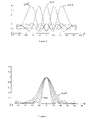
- FIG. 2 shows the amplitude of the response of the sum of all the feeds from the microphone array with changing angle of incidence for different wavelengths.
- FIG. 3 shows the effect of “steering” the array by adding a simple delay to each microphone.
- FIG. 4 shows the effect of using a window function to change the tradeoff between center lobe width and side lobe suppression.
- FIG. 5 shows three overlapping arrays sharing center microphones.
- FIG. 6 is a plot of Beta parameter to Kaiser-Bessel window for values of wavelength in multiples of the microphone spacing.
- FIG. 7 shows lobe widths after normalization by adjusting the Beta parameter of the Kaiser-Bessel window.
- FIG. 8 are typical windowing gain curves representing particular points of the Kaiser-Bessel window as the Beta parameter is swept as shown in FIG. 6 .
- FIG. 9 is a block diagram of processing for overlapped microphone arrays.
- FIG. 10 shows the response of one kind of prototype overlap filter covering the band from 2000 Hz to 4000 Hz.
- FIG. 11 is a diagram of a pressure-gradient condenser microphone.
- FIG. 12 shows a regular 2-dimensional array with equal resolution in horizontal and vertical directions.
- FIG. 13 is a 2-dimensional microphone array showing unequal resolution in vertical and horizontal directions.
- FIG. 14 shows two 2-dimensional arrays placed at right angles.
- FIG. 15 shows an embodiment of the processing for a microphone in the array.
- FIG. 16 shows an embodiment including the preprocessing and A/D conversion in the same physical location as the microphone capsule itself.
- FIG. 17 shows an embodiment as a microphone array “fabric”.
- the second term of the above represents the amplitude of the resulting sum. This is plotted for various values of wavelength in FIG. 2 , that shows the amplitude of the response of the sum of all the feeds from the microphone array with changing angle of incidence. Each curve represents a different wavelength from 1.5d (narrowest) 201 to 6d (widest) 210 . Note that the maximum response is developed in a direction perpendicular to the microphone array. The varying width of the response maximum show that different wavelengths will have different pickup patterns.
- the entire array can be “steered” by applying a simple delay to each microphone as follows:
- ⁇ ⁇ ⁇ t k - kd c ⁇ sin ⁇ ⁇ ⁇ , ( 3 ) where ⁇ is the angle where the greatest sensitivity is desired.
- the wavelength of the test signal was set to a constant 2.5d. Note that the main response widens a bit as the array is steered away from the center. This is because the “effective” microphone spacing is reduced by the cosine of the angle.
- FIG. 4 shows the effect of changing the strength of the window.
- the window was the Kaiser-Bessel window with the ⁇ parameter varying between 0.5 in curve 401 and 5.5 in curve 403 , where lobe width increases with increasing window strength. More information on window functions is given, for example, in Leland B. Jackson “Digital Filters and Signal Processing,” Kluwer Academic Publishers, Hingham, Mass. USA, 1986—see Section 9.1, pp 128–134, which is hereby incorporated by this reference.
- the basic array exhibits reasonable response over about 2 octaves covering wavelengths from about 1.5d and 6d. Wavelengths longer than this produces very wide principal lobes, and wavelengths shorter than this produce multiple principal lobes.
- the center octave of this in a geometric-mean sense) can be taken as the main region of response, which is from about 2.12d to about 4.14d. The remainder of the response range will be used to overlap with other arrays that cover other octaves.
- FIG. 5 shows a simplified diagram with three colinear arrays with spacings at d, 2d and 4d and five microphones for each spacing.
- microphone 503 has both the spacings d and 2d
- microphone 502 has both the spacings 2d and 4d.
- an exemplary embodiment would have a total of ten array spacings.
- Each array will contribute one octave of frequency response to the overall result.
- the upper and lower half-octave of each array will overlap with the adjacent arrays.
- a window function can be used to adjust the width of the center lobe. Since a different lobe width is preferably used at each different frequency, the output of each array is filtered with individual filters that are designed to realize a certain window function at each frequency. The filters should also sum properly with the responses of adjacent arrays to produce flat frequency response and uniform lobe width when summed over all the arrays.
- FIG. 6 is a plot of the beta parameter to Kaiser-Bessel window for values of wavelength expressed in multiples of the microphone spacing. These values of beta equalize the main lobe widths for the given wavelength. This curve appears to be largely independent of the number of microphones in the array. As the wavelength moves from 6d down to 1.5d, the beta parameter can be increased steadily to widen the principal lobe.
- FIG. 7 shows the result of applying different window functions to the array at different wavelengths and shows lobe widths after normalization by adjusting the Beta parameter of the Kaiser-Bessel window.
- the wavelengths span the range from 1.5d to 6d.
- the sideband gain increases at the ends of the frequency range due to the windowing. This is using 15 microphones in a single array. Note that at the shortest wavelength, the sideband rejection starts to rise again, probably due to the effective “shortening” of the array.
- FIG. 8 is a typical windowing gain curves for four microphones in a 9-microphone array at various values of wavelength (in multiples of d). These represent particular points of the Kaiser-Bessel window as the Beta parameter is swept as shown in FIG. 6 .
- the upper curve represents the center microphone, and the center point of the window function.
- D i represents the “desired” response.
- a desired response can be produced by windowing the response at the maximum wavelength of 6d. Using this as the prototype response, this can be matched as closely as desired by choosing the weighting function, p i , and finding the window function coefficients, w k , that minimize F in equation (4).
- equation (4) represents a linear least-squares problem.
- the normal equations can be formed and solved by any number of methods, such as singular-value decomposition (described, for example, in sections 2.5 and 8.6 of Gene H. Golub, Charles F. Van Loan “Matrix Computations: Third Edition” Johns Hopkins University Press, Baltimore Md. USA, 1996, which is hereby incorporated by reference).
- singular-value decomposition described, for example, in sections 2.5 and 8.6 of Gene H. Golub, Charles F. Van Loan “Matrix Computations: Third Edition” Johns Hopkins University Press, Baltimore Md. USA, 1996, which is hereby incorporated by reference.
- Kaiser-Bessel window is relatively simple, this embodiment is used in the remainder of this discussion with the understanding that any suitable window that allows matching of the principal lobes can be used.
- a filter is implemented for each microphone that has the desired gain at each wavelength. This gain is determined by the value of the Kaiser-Bessel window for that microphone at the value of beta indicated by the curve of FIG. 6 .
- the resulting window function is, in fact, a family of window functions, since the window function will be different for each different frequency. This can be represented this as w k ( ⁇ ) for the weighting of microphone k at a wavelength of ⁇ .
- FIG. 7 shows a plot of four different microphone coefficients as functions of wavelength. These represent the filters that must be realized to produce equal main lobe widths over the frequency range of interest. There are many ways to calculate the filter coefficients, such as the methods described in Leland B.
- window functions are symmetric. This means that for an array of n microphone, only (n ⁇ 1)/2 windowing filters need be implemented. Microphones on each side of the center microphone may be summed before filtering, thus eliminating the need for a number of filters, although the steering delays will differ for the two sides.
- FIG. 9 is a block diagram of processing for overlapped microphone arrays in an exemplary embodiment with two spacings, each having five microphones.
- Each microphone goes to a filter that implements the frequency-dependent window and the “steering” delay, if these are included.
- microphone 901 which corresponds to a spacing 2d
- windowing filter 915 goes into windowing filter 915 .
- Microphone 902 which corresponds to a spacing of both d and 2d, goes to two windowing filters, being connected to adder 930 for the spacing d through the filter 930 and being connected to adder 931 for the spacing 2d through the filter 916 .
- Each windowed array is then filtered so that the arrays overlap properly to produce an overall flat response when combined by adder 960 .
- the array with the spacing d is filtered through overlap filter 950 after the windowed responses are combined in adder 930 , with filter 951 and adder 931 serving the function for the array with spacing 2d.
- One windowing filter is shown for each microphone for clarity. Since the window functions are symmetric, pairs of microphones equidistant from the center microphone, for example 901 and 907 , could be summed (after receiving the appropriate steering delay), then filtered by a single frequency-dependent window filter so that, in the case of 901 and 907 , filters 915 and 919 would then be the same filter.
- each array covers about two octaves. This can be separated into the main region, from about 2.12d to about 4.14d, and the overlap regions, which constitute the remainder of the full two octave range. At the extremes of the frequency range, there is no overlap, so the highest array will cover up to 1.5 d r and the lowest array will cover down to 6d l , where d j represents the microphone spacing of array j.
- d j represents the microphone spacing of array j.
- the frequencies of Table 1 are not exact, but have been rounded to convenient boundaries for clarity. Note again that the highest frequency array extends from 1.5d to 4.14d, and the lowest frequency band extends from 2.12d to 6d. All the others extend from 2.12d to 4.14d. This shows that the entire frequency range may be captured by 9 collinear arrays, each having twice the spacing of the next. If desired, the larger arrays at lower frequencies may be eliminated. The only effect of this is that the pickup will not be highly directional at low frequencies due to the widening of the principal lobe of the array response.
- the width of the principal lobe is acceptable to change, as long as other properties of the array are preserved, such as overall frequency response flatness, and matching of the principal lobes among the arrays to prevent coloration of the sound in the principal lobe.
- each array contributes to the overall response mainly in its principal frequency region. It is preferable that the sum of the responses across all the arrays be flat over the audible range. This can be expressed by considering the impulse response of each array, then stating conditions on these responses which represent the design goals. For convenience the impulse response of each array can be taken as symmetric. This is not strictly necessary, but it guarantees that there will be no phase variance from one array to the next. If the impulse response of filter i at a time point s is represented by h is , the conditions for flatness of overall frequency response can be stated as follows:
- the process can start by first creating an “ideal” prototype filter that is constructed so that it overlaps perfectly, followed by computing approximations to the prototype filter using standard approximation techniques (see, for example, J. H. McClellan, T. W. Parks, L. R. Rabiner “A Computer Program for Designing Optimum FIR Linear Phase Digital Filters” incorporated by reference above).
- a separate prototype filter is preferably created for each band, there are some similarities that make the process simpler.
- the process can separate the filters into the two at the extremes of frequency, and all the rest. For the filters that are not at the extremes, it can be required that they are identical, except that each band spans twice the frequency of the previous band.
- a filter can be defined as follows: f c ⁇ (4/3) f (6) f 1 ⁇ (2/3) f (7) f 2 ⁇ (8/3) f (8)
- H ⁇ ( ⁇ ) ⁇ 0 ⁇ ⁇ f 1 ( ⁇ - f 1 ) / ( f c - f 1 ) f 1 ⁇ ⁇ ⁇ f c ( f 2 - ⁇ ) / ( f 2 - f c ) f c ⁇ ⁇ ⁇ f 2 0 f 2 ⁇ ⁇ ( 9 )
- FIG. 10 shows a plot of this function for the frequency band 2000–4000 Hz.
- the filter extends down to 1333 Hz and up to 5333 Hz and up to 5333 Hz for proper overlap. It will perfectly overlap the filters in the next higher and next lower frequency bands, and the sum of these overlapping filters is exactly one by construction.
- the filter for the next higher or lower frequency band may be obtained simply by relabeling the frequency axis with either twice the frequencies or half the frequencies. Of course, this filter design is not unique. There are many suitable choices for the overlap filter that have this property.
- the filter can simply be taken to stay at unity gain on one side or the other.
- the filters for the extremes can be defined as follows:
- H ⁇ ( ⁇ ) ⁇ 1 ⁇ ⁇ f c ( f 2 - ⁇ ) / ( f 2 - f c ) f c ⁇ ⁇ ⁇ f 2 0 f 2 ⁇ ⁇ ( 10 )
- H ⁇ ( ⁇ ) ⁇ 0 ⁇ ⁇ f 1 ( ⁇ - f 1 ) / ( f c - f 1 ) f 1 ⁇ ⁇ ⁇ f c 1 f c ⁇ ⁇ ( 11 )
- filter coefficients that approximate these filters to any degree of accuracy may be computed. If the filters are all of zero-phase, then they will sum to an approximation of an impulse, described by Equation (5). This is by construction. Since the sum of all the prototype filters is unity, the resulting impulse response must be a simple impulse. Consequently, the sum of a series of filters that approximate the prototype filters will naturally be an approximation to an impulse. Of course, if the filters are not of zero-phase or linear-phase design, they will not necessarily sum to an impulse.
- the effective shortening of the microphone spacing by the factor of cos( ⁇ ) indicates that all the filters, both the windowing filters and the overlapping filters, should be recomputed using a microphone spacing of d cos( ⁇ ).
- the beta parameter of the Kaiser-Bessel window may be adjusted so that the width of the principal lobes remains constant over the usable steering range of ⁇ 45° to 45°.
- FIG. 11 shows a schematic representation of a pressure-gradient condenser microphone 1100 .
- the neutral interior capsule 1107 is held at ground, and the variations of capacitance between the anterior and posterior diaphragms, respectively 1103 and 1105 , and the capsule 1107 generate a voltage.
- the voltages of the anterior and posterior diaphragms may be weighted and subtracted. This produces the familiar directional patterns, such as cardioid, hypercardioid, and so on.
- This kind of microphone has the following angular response: C +(1 ⁇ C )cos( ⁇ ) (12)
- the response straight ahead (zero angle) is exactly one.
- the response to the rear is (2C ⁇ 1).
- C is set to one-half, so the response to the rear is exactly zero.
- Other values of C produce different patterns.
- Equation (12) The effect of using a pressure-gradient microphone in this array is that the off-angle response will be multiplied by the directional pattern described by Equation (12).
- the effect would be that, for instance, the plot shown in FIG. 3 would also show an amplitude difference as the principal lobe was steered from left to right. All the curves in FIG. 3 would be multiplied by Equation (12). Note that the peak amplitude of the principal lobes in FIG. 3 can be normalized by simply correcting for the expected attenuation due to the directional characteristics of the microphones.
- a single array of pressure-gradient microphones can be used to mix the feeds of the diaphragms differently so that the same microphone array may be used for sounds in front of the array and behind the array with equal angular resolution and identical fidelity (frequency-response).
- filtering similar to that shown in FIG. 9 would be duplicated for the rear-facing array.
- phased-array radar there is always the explicit assumption that the incoming wave is a plane wave.
- the plane wave assumption may be used when the sound sources are sufficiently distant from the microphone itself. If this is not the case, the wavefront will be curved. This curvature may corrected if the location of the sound source is known. If the plane-wave approximation can be made, the distance between the sound source and the array is not needed.
- a correction is applied to the amplitude and to the arrival time.
- the amplitude correction is needed to offset the 1/r 2 attenuation the wavefront experiences.
- the correction to the arrival time is necessary since the curvature will have the effect of delaying the off-center parts of the wavefront. This can be quantized as follows: Let ⁇ and r 0 be the angle and distance from the sound source to the center microphone of the array. The amplitude and time delay compensation is then:
- r n the distance from the sound source to microphone n.
- the feed from microphone n should be multiplied by P n and should be advanced by ⁇ n seconds.
- the response in a particular direction can be enhanced by subtracting off the signals from the known directions.
- the delays across the varying angles must be equalized before a signal from one angle can be subtracted from a signal from another angle. This can be though of as a kind of analog to the lateral inhibition found in optical receptors in the retina of the eye.
- a worst-case bound on the error in the array can be obtained by taking the second term of Equation (2), applying a window function, assuming that the cosine term is always unity, and assuming that the microphone error is a uniform factor of ⁇ . This gives the following upper bound:
- a mean deviation of 1 dB then will produce error in the resulting pickup pattern that is about 18 dB down.
- the error discussed here is a distortion of the pickup pattern itself, as shown in FIGS. 2 , 3 , and 4 . This is not so important for the principal lobe, but it can make a significant difference in the sideband suppression, since in some cases, the error will be of the same order of magnitude as the sideband amplitude itself. It can be expected that the actual sideband rejection will be several dB less than the theoretical values with a 1 dB variation among the microphones. Of course, better matching will allow more sideband rejection.
- the room reverberation may (somewhat artificially) be divided into three epochs: the direct sound, the early reflections, and everything else.
- the direct sound and the early reflections can all be treated as point sources of sound.
- the array can be steered to pick up each one of these sources separately (or not, depending on the goals of the recording).
- the late reverberation can be considered to be omnidirectional, and will thus affect the array uniformly regardless of the steering direction.
- non-uniform reflections such as slap echoes, will appear as specular reflections and thus will appear as point sources to the array.
- the discussion may also be extended to more general arrangements.
- To extend the phased-array microphone to three dimensions it must first extended to two dimensions. This can be done by extending the array as shown in FIG. 12 .
- FIG. 13 shows an array 1300 with higher resolution in the horizontal direction than in the vertical direction.
- a more general arrangement need not use orthogonal axes to determine the spacing of the array. In this last case, the non-orthogonality can be compensated for in the signal processing.
- a single 2-dimensional array can only be steered across about a 90° range in the forward direction and a 90° range in the reverse direction.
- multiple non-coplanar 2-dimensional arrays may be used.
- the simpler case 1400 of two arrays at right angles is shown in FIG. 14 . Note that for this to work best, each array would preferably be acoustically “transparent”, so that off-axis sounds will easily pass through it to reach the other array.
- two 2-dimensional arrays shown in FIG. 14 can be taken and another array in the horizontal plane placed to cover the vertical direction. In this manner, pickup in any direction can be achieved.
- FIG. 15 shows the processing for each microphone in the array in such an embodiment.
- the array has a wire from each microphone 1501 in the array to the required preprocessing, including microphone preamplifier 1503 and A/D converter 1505 .
- the output, along with that from other microphones in the array, then goes on to subsequent processing as shown in FIG. 9 .
- the use of electret or other microphone technology may render the pre-amplifier unnecessary.
- the result of the preprocessing is a sequence of digital audio samples. Since a large array may contain hundreds of microphones, running individual wires from each microphone to the required pre-processing and subsequent processing may be undesirable.
- the microphone capsule integrates the microphone 1601 with the pre-processing as the integrated pre-processor 1600 .
- miniaturized preamplifier 1603 and A/D stages 1605 are integrated with some kind of multiplexing (network) interface that combines the signal with those of the other microphones.
- some kind of data multiplexing circuit is included with each microphone so that the outputs of multiple microphones may be combined into a single wire.
- multiplexing technology may be used, ranging from simple time-domain or frequency-domain multiplexing (see, for example, U.S. Pat. No.
- FIG. 17 shows the extension of this sort of embodiment to the microphone array “fabric”.
- power is fed to each transducer/processor/multiplexor node via alternating vertical positive and negative supply wires.
- Each oval, such as 1701 represents a complete transducer, preprocessor, and network interface as shown in FIG. 16 .
- This figure shows how the array may be powered by a vertical array of alternating positive, such as 1711 , and negative supplies, such as 1713 .
- One rail e.g. the positive wires like as 1711
- clock distribution to the individual A/D converters may be accomplished by placing the clock itself on one of the supply wires. By use of frequency-domain multiplexing, the data can be placed on the wire in frequency bands that are well above the clock frequency.
- Each node could simply broadcast a low-power RF signal that could be received and demultiplexed for further processing.
- Each node would have some unique ID in the form of a network address, a dedicated frequency, a dedicated time slot, or any other way of identifying the node so that the samples may be recovered and related back to the original array position of the node.
- each node could emit digital data as light on wavelengths that people can not see.
- the data could be multiplexed either by the wavelength of the individual lights, or by time so that only one node transmitted data at a time.
- Clusters of some number of nodes in a particular area could be multiplexed together with, say, fiber-optic cables used to relay the data from each cluster back to the spatial processing equipment.
Abstract
Description
For convenience, let the number of microphones be odd, and call the center microphone number zero. The discussion readily extends to the even number case, although the odd case is presented more fully here as it allows a greater degree of microphone sharing between different spacing in arrangements such as
The second term of the above represents the amplitude of the resulting sum. This is plotted for various values of wavelength in
where Φ is the angle where the greatest sensitivity is desired.
where Di represents the “desired” response. In the present example case, a desired response can be produced by windowing the response at the maximum wavelength of 6d. Using this as the prototype response, this can be matched as closely as desired by choosing the weighting function, pi, and finding the window function coefficients, wk, that minimize F in equation (4). Since the response of the array is linear with respect to any given window coefficient, equation (4) represents a linear least-squares problem. The normal equations can be formed and solved by any number of methods, such as singular-value decomposition (described, for example, in sections 2.5 and 8.6 of Gene H. Golub, Charles F. Van Loan “Matrix Computations: Third Edition” Johns Hopkins University Press, Baltimore Md. USA, 1996, which is hereby incorporated by reference). One might choose, for instance, pi≡1 to match the desired response as well as possible over the entire function. One might choose pi=10 over the main lobe and pi=1 elsewhere to force the response to match the desired response as well as possible at the main lobe and less well outside the main lobe.
| TABLE 1 | |||
| Microphone | Low | High | |
| | Frequency | Frequency | |
| 1 | cm | 8000 | Hz | 22067 | Hz |
| 2 | | 4000 | Hz | 8000 | Hz |
| 4 | | 2000 | Hz | 4000 | Hz |
| 8 | | 1000 | Hz | 2000 | Hz |
| 16 | cm | 500 | Hz | 1000 | Hz |
| 32 | cm | 250 | Hz | 500 | Hz |
| 64 | cm | 125 | Hz | 250 | Hz |
| 1.28 | m | 62.5 | Hz | 125 | Hz |
| 2.56 | m | 22.11 | Hz | 62.5 | Hz |
More generally, if the minimum spacing is taken to be centered at a frequency of, say, 3–20 kHz, this corresponds to a d in the range of about 10 cm≧d≧0.5 cm.
This is necessary and sufficient to guarantee perfectly flat frequency response. In general, this condition will not be met exactly. All that is required is that the deviation from identity be sufficiently small so it is not heard as an excessive coloration of the sound.
f c≡(4/3)f (6)
f 1≡(2/3)f (7)
f 2≡(8/3)f (8)
C+(1−C)cos(θ) (12)
The response straight ahead (zero angle) is exactly one. The response to the rear is (2C−1). For a cardioid pattern, C is set to one-half, so the response to the rear is exactly zero. Other values of C produce different patterns.
where rn represents the distance from the sound source to microphone n. The feed from microphone n should be multiplied by Pn and should be advanced by Δn seconds.
The window function is normalized so that the above sum (across all the points of the window function) is unity, so the error is bounded by the individual microphone error. The parameter s can be taken to represent the expected value of the error. Some microphones will exhibit somewhat more error and some will exhibit somewhat less.
Claims (13)
Priority Applications (2)
| Application Number | Priority Date | Filing Date | Title |
|---|---|---|---|
| US09/919,742 US7068796B2 (en) | 2001-07-31 | 2001-07-31 | Ultra-directional microphones |
| US11/419,460 US7756278B2 (en) | 2001-07-31 | 2006-05-19 | Ultra-directional microphones |
Applications Claiming Priority (1)
| Application Number | Priority Date | Filing Date | Title |
|---|---|---|---|
| US09/919,742 US7068796B2 (en) | 2001-07-31 | 2001-07-31 | Ultra-directional microphones |
Related Child Applications (1)
| Application Number | Title | Priority Date | Filing Date |
|---|---|---|---|
| US11/419,460 Continuation US7756278B2 (en) | 2001-07-31 | 2006-05-19 | Ultra-directional microphones |
Publications (2)
| Publication Number | Publication Date |
|---|---|
| US20030072461A1 US20030072461A1 (en) | 2003-04-17 |
| US7068796B2 true US7068796B2 (en) | 2006-06-27 |
Family
ID=25442575
Family Applications (2)
| Application Number | Title | Priority Date | Filing Date |
|---|---|---|---|
| US09/919,742 Expired - Lifetime US7068796B2 (en) | 2001-07-31 | 2001-07-31 | Ultra-directional microphones |
| US11/419,460 Active 2024-06-14 US7756278B2 (en) | 2001-07-31 | 2006-05-19 | Ultra-directional microphones |
Family Applications After (1)
| Application Number | Title | Priority Date | Filing Date |
|---|---|---|---|
| US11/419,460 Active 2024-06-14 US7756278B2 (en) | 2001-07-31 | 2006-05-19 | Ultra-directional microphones |
Country Status (1)
| Country | Link |
|---|---|
| US (2) | US7068796B2 (en) |
Cited By (12)
| Publication number | Priority date | Publication date | Assignee | Title |
|---|---|---|---|---|
| US20070053524A1 (en) * | 2003-05-09 | 2007-03-08 | Tim Haulick | Method and system for communication enhancement in a noisy environment |
| US20090103741A1 (en) * | 2005-05-18 | 2009-04-23 | Real Sound Lab, Sia | Method of correction of acoustic parameters of electro-acoustic transducers and device for its realization |
| US20110103612A1 (en) * | 2009-11-03 | 2011-05-05 | Industrial Technology Research Institute | Indoor Sound Receiving System and Indoor Sound Receiving Method |
| US20120167691A1 (en) * | 2009-07-07 | 2012-07-05 | Siemens Aktiengesellschaft | Method for recording and reproducing pressure waves comprising direct quantification |
| US20130064391A1 (en) * | 2011-09-13 | 2013-03-14 | Space Administration | Acoustic Beam Forming Array Using Feedback-Controlled Microphones for Tuning and Self-Matching of Frequency Response |
| CN101296529B (en) * | 2007-04-25 | 2013-07-10 | 哈曼贝克自动系统股份有限公司 | Sound tuning method and system |
| US9002028B2 (en) | 2003-05-09 | 2015-04-07 | Nuance Communications, Inc. | Noisy environment communication enhancement system |
| CN104969569A (en) * | 2013-01-11 | 2015-10-07 | 无线电广播技术研究所有限公司 | Microphone arrangement with improved directional characteristic |
| US9502050B2 (en) | 2012-06-10 | 2016-11-22 | Nuance Communications, Inc. | Noise dependent signal processing for in-car communication systems with multiple acoustic zones |
| US9613633B2 (en) | 2012-10-30 | 2017-04-04 | Nuance Communications, Inc. | Speech enhancement |
| US9805738B2 (en) | 2012-09-04 | 2017-10-31 | Nuance Communications, Inc. | Formant dependent speech signal enhancement |
| US20180115759A1 (en) * | 2012-12-27 | 2018-04-26 | Panasonic Intellectual Property Management Co., Ltd. | Sound processing system and sound processing method that emphasize sound from position designated in displayed video image |
Families Citing this family (27)
| Publication number | Priority date | Publication date | Assignee | Title |
|---|---|---|---|---|
| WO2003105124A1 (en) * | 2002-06-11 | 2003-12-18 | Sony Electronics Inc. | Microphone array with time-frequency source discrimination |
| EP1475997A3 (en) * | 2003-05-09 | 2004-12-22 | Harman/Becker Automotive Systems GmbH | Method and system for communication enhancement in a noisy environment |
| US7305886B2 (en) * | 2004-06-07 | 2007-12-11 | Board Of Trustees Of Michigan State University | Noise detecting apparatus |
| EA011601B1 (en) * | 2005-09-30 | 2009-04-28 | Скуэрхэд Текнолоджи Ас | A method and a system for directional capturing of an audio signal |
| US20070250391A1 (en) * | 2006-04-05 | 2007-10-25 | Prade Hendrik D | Merchandising system and method for food and non-food items for a meal kit |
| US8555721B2 (en) * | 2007-12-27 | 2013-10-15 | Scott Taillet | Sound measuring device |
| TWI450602B (en) * | 2012-06-06 | 2014-08-21 | Nat Univ Tsing Hua | A micro-size electronic shotgun microphone |
| JP2014011600A (en) * | 2012-06-29 | 2014-01-20 | Audio Technica Corp | Microphone |
| US9232310B2 (en) * | 2012-10-15 | 2016-01-05 | Nokia Technologies Oy | Methods, apparatuses and computer program products for facilitating directional audio capture with multiple microphones |
| US9565493B2 (en) | 2015-04-30 | 2017-02-07 | Shure Acquisition Holdings, Inc. | Array microphone system and method of assembling the same |
| US9554207B2 (en) | 2015-04-30 | 2017-01-24 | Shure Acquisition Holdings, Inc. | Offset cartridge microphones |
| US9756421B2 (en) * | 2016-01-22 | 2017-09-05 | Mediatek Inc. | Audio refocusing methods and electronic devices utilizing the same |
| US10367948B2 (en) | 2017-01-13 | 2019-07-30 | Shure Acquisition Holdings, Inc. | Post-mixing acoustic echo cancellation systems and methods |
| US11523212B2 (en) * | 2018-06-01 | 2022-12-06 | Shure Acquisition Holdings, Inc. | Pattern-forming microphone array |
| US11297423B2 (en) | 2018-06-15 | 2022-04-05 | Shure Acquisition Holdings, Inc. | Endfire linear array microphone |
| CN112889296A (en) | 2018-09-20 | 2021-06-01 | 舒尔获得控股公司 | Adjustable lobe shape for array microphone |
| CN113841421A (en) | 2019-03-21 | 2021-12-24 | 舒尔获得控股公司 | Auto-focus, in-region auto-focus, and auto-configuration of beamforming microphone lobes with suppression |
| EP3942842A1 (en) | 2019-03-21 | 2022-01-26 | Shure Acquisition Holdings, Inc. | Housings and associated design features for ceiling array microphones |
| US11558693B2 (en) | 2019-03-21 | 2023-01-17 | Shure Acquisition Holdings, Inc. | Auto focus, auto focus within regions, and auto placement of beamformed microphone lobes with inhibition and voice activity detection functionality |
| TWI723376B (en) * | 2019-04-15 | 2021-04-01 | 美律實業股份有限公司 | Hearing aid device |
| TW202101422A (en) | 2019-05-23 | 2021-01-01 | 美商舒爾獲得控股公司 | Steerable speaker array, system, and method for the same |
| TW202105369A (en) | 2019-05-31 | 2021-02-01 | 美商舒爾獲得控股公司 | Low latency automixer integrated with voice and noise activity detection |
| US11297426B2 (en) | 2019-08-23 | 2022-04-05 | Shure Acquisition Holdings, Inc. | One-dimensional array microphone with improved directivity |
| US11552611B2 (en) | 2020-02-07 | 2023-01-10 | Shure Acquisition Holdings, Inc. | System and method for automatic adjustment of reference gain |
| USD944776S1 (en) | 2020-05-05 | 2022-03-01 | Shure Acquisition Holdings, Inc. | Audio device |
| US11706562B2 (en) | 2020-05-29 | 2023-07-18 | Shure Acquisition Holdings, Inc. | Transducer steering and configuration systems and methods using a local positioning system |
| WO2022165007A1 (en) | 2021-01-28 | 2022-08-04 | Shure Acquisition Holdings, Inc. | Hybrid audio beamforming system |
Citations (17)
| Publication number | Priority date | Publication date | Assignee | Title |
|---|---|---|---|---|
| GB2097121A (en) | 1981-04-21 | 1982-10-27 | Ferranti Ltd | Directional acoustic receiving array |
| GB2104218A (en) | 1981-07-28 | 1983-03-02 | Ferranti Ltd | Detecting harmonically-rich acoustic sources |
| US4703506A (en) | 1985-07-23 | 1987-10-27 | Victor Company Of Japan, Ltd. | Directional microphone apparatus |
| US4741038A (en) * | 1986-09-26 | 1988-04-26 | American Telephone And Telegraph Company, At&T Bell Laboratories | Sound location arrangement |
| US4802227A (en) | 1987-04-03 | 1989-01-31 | American Telephone And Telegraph Company | Noise reduction processing arrangement for microphone arrays |
| US4922536A (en) | 1988-11-14 | 1990-05-01 | Massachusetts Institute Of Technology | Digital audio transmission for use in studio, stage or field applications |
| US5051799A (en) | 1989-02-17 | 1991-09-24 | Paul Jon D | Digital output transducer |
| US5058170A (en) | 1989-02-03 | 1991-10-15 | Matsushita Electric Industrial Co., Ltd. | Array microphone |
| US5483599A (en) | 1992-05-28 | 1996-01-09 | Zagorski; Michael A. | Directional microphone system |
| US5684882A (en) * | 1994-07-15 | 1997-11-04 | France Telecom | System for selective sound capture for reverberant and noisy environment |
| US5737430A (en) | 1993-07-22 | 1998-04-07 | Cardinal Sound Labs, Inc. | Directional hearing aid |
| US5848170A (en) * | 1995-12-22 | 1998-12-08 | France Telecom | Acoustic antenna for computer workstation |
| WO1999027754A1 (en) | 1997-11-20 | 1999-06-03 | Conexant Systems, Inc. | A system for a monolithic directional microphone array and a method of detecting audio signals |
| US5940118A (en) | 1997-12-22 | 1999-08-17 | Nortel Networks Corporation | System and method for steering directional microphones |
| WO1999053336A1 (en) | 1998-04-13 | 1999-10-21 | Andrea Electronics Corporation | Wave source direction determination with sensor array |
| WO2000052959A1 (en) | 1999-03-05 | 2000-09-08 | Etymotic Research, Inc. | Directional microphone array system |
| US6952697B1 (en) | 2002-06-21 | 2005-10-04 | Trust Licensing, Llc | Media validation system |
Family Cites Families (4)
| Publication number | Priority date | Publication date | Assignee | Title |
|---|---|---|---|---|
| FR2447542A1 (en) * | 1979-01-29 | 1980-08-22 | Metravib Sa | APPARATUS FOR MEASURING THE TOTAL OR DIRECTIONAL SOUND POWER EMITTED BY ANY SOURCE |
| US5793875A (en) * | 1996-04-22 | 1998-08-11 | Cardinal Sound Labs, Inc. | Directional hearing system |
| NZ502603A (en) * | 2000-02-02 | 2002-09-27 | Ind Res Ltd | Multitransducer microphone arrays with signal processing for high resolution sound field recording |
| JP2003530051A (en) * | 2000-03-31 | 2003-10-07 | クラリティー リミテッド ライアビリティ カンパニー | Method and apparatus for audio signal extraction |
-
2001
- 2001-07-31 US US09/919,742 patent/US7068796B2/en not_active Expired - Lifetime
-
2006
- 2006-05-19 US US11/419,460 patent/US7756278B2/en active Active
Patent Citations (17)
| Publication number | Priority date | Publication date | Assignee | Title |
|---|---|---|---|---|
| GB2097121A (en) | 1981-04-21 | 1982-10-27 | Ferranti Ltd | Directional acoustic receiving array |
| GB2104218A (en) | 1981-07-28 | 1983-03-02 | Ferranti Ltd | Detecting harmonically-rich acoustic sources |
| US4703506A (en) | 1985-07-23 | 1987-10-27 | Victor Company Of Japan, Ltd. | Directional microphone apparatus |
| US4741038A (en) * | 1986-09-26 | 1988-04-26 | American Telephone And Telegraph Company, At&T Bell Laboratories | Sound location arrangement |
| US4802227A (en) | 1987-04-03 | 1989-01-31 | American Telephone And Telegraph Company | Noise reduction processing arrangement for microphone arrays |
| US4922536A (en) | 1988-11-14 | 1990-05-01 | Massachusetts Institute Of Technology | Digital audio transmission for use in studio, stage or field applications |
| US5058170A (en) | 1989-02-03 | 1991-10-15 | Matsushita Electric Industrial Co., Ltd. | Array microphone |
| US5051799A (en) | 1989-02-17 | 1991-09-24 | Paul Jon D | Digital output transducer |
| US5483599A (en) | 1992-05-28 | 1996-01-09 | Zagorski; Michael A. | Directional microphone system |
| US5737430A (en) | 1993-07-22 | 1998-04-07 | Cardinal Sound Labs, Inc. | Directional hearing aid |
| US5684882A (en) * | 1994-07-15 | 1997-11-04 | France Telecom | System for selective sound capture for reverberant and noisy environment |
| US5848170A (en) * | 1995-12-22 | 1998-12-08 | France Telecom | Acoustic antenna for computer workstation |
| WO1999027754A1 (en) | 1997-11-20 | 1999-06-03 | Conexant Systems, Inc. | A system for a monolithic directional microphone array and a method of detecting audio signals |
| US5940118A (en) | 1997-12-22 | 1999-08-17 | Nortel Networks Corporation | System and method for steering directional microphones |
| WO1999053336A1 (en) | 1998-04-13 | 1999-10-21 | Andrea Electronics Corporation | Wave source direction determination with sensor array |
| WO2000052959A1 (en) | 1999-03-05 | 2000-09-08 | Etymotic Research, Inc. | Directional microphone array system |
| US6952697B1 (en) | 2002-06-21 | 2005-10-04 | Trust Licensing, Llc | Media validation system |
Non-Patent Citations (17)
| Title |
|---|
| Andrew G. Deczky "Synthesis of Recursive Digital Filters Using the Minimum p-Error Criterion" IEEE Transactions on Audio and Electroacoustics, vol. AU-20, pp. 257-263, Oct. 1972. [0039]. |
| B.R. Beavers, R. Brown "Third-Order Gradient Microphone for Speech Reception" Journal of the Audio Engineering Society, Dec. 1970. [0002] NOTE: These two articles, 1) and 2), are included in Microphones: An Anthology of Articles on Microphones from the Pages of the Journal of the Audio. |
| Berhout et al., "Acoustic Control By Wave-Field Synthesis," Journal of the Acoustic Society of America, vol. 5, pp. 2764-2778, 1993. |
| Chou, Thomas, "Frequency-Independent Beamformer With Low Response Error," IEEE Conference on Acoustics, Speech, and Signal Processing, vol. 5, pp. 2995-2998, 1995. |
| Flanagan, J.H. et al. "Autodirective Micro Systems," Acustica, vol. 73, pp. 58-71, 1991. |
| Gerzon, Michael, "Ultra-Directional Microphones: Applications of Blumlein Difference Technique: Part 1," Studio Sound, vol. 12, Oct. 1970, pp. 434-437. |
| Gerzon, Michael, "Ultra-Directional Microphones: Applications of Blumlein Difference Technique: Part 2," Studio Sound, vol. 12, Nov. 1970, pp. 501-504. |
| Gerzon, Michael, "Ultra-Directional Microphones: Applications of Blumlein Difference Technique: Part 3," Studio Sound, vol. 12, Dec. 1970, pp. 539-543. |
| Goodwin Michael M.; Elko, Gary W., "Constant Beamwidth Beamforming," IEE Conference on Acoustics, Speech, and Signal Processing, vol. 4, pp. I-169-I-172, 1993. |
| Harry F. Olson "Directional Microphones," Journal of the Audio Engineering Society, Oct. 1967. [0002]. |
| J.H. McClellan, T.W. Parks, L.R. Rabiner "A Computer Program for Designing Optimum FIR Linear Phase Digital Filters" IEEE Transactions on Audio and Electroacoustics, vol. AU-21, pp. 506-526, Dec. 1973. [0039]. |
| Metcalfe, R.M., and Boggs, D.R. "Ethernet: Distributed Packet Switching for Local Computer Networks", Communications of the ACM, vol. 19, No. 7, pp. 395-404, Jul. 1976. [0072]. |
| Patrick M. Peterson "Adaptive Array Processing for Multiple Microphone Hearing Aids" RLE Technical Report No. 541, Feb. 1989. (This is from: RLE (Research Laboratory of Electronics), MIT, Cambridge, MA 02139. |
| Peacock, Kenneth L., "On the Practical Design of Discrete Velocity Filters for Seismic Data Processing," IEEE Transactions on Acoustics, Speech, and Signal Processing, vol. ASSP-30, No. 1, Feb. 1982, pp. 52-60. |
| Section 9.1, pp. 128-134, of Leland B. Jackson "Digital Filters and Signal Processing," Kluwer Academic Publishers, Hingham, MA USA, 1996. [0029]. |
| Sections 2.5 and 8.6 of Gene H. Golub, Charles F. Van Loan "Matrix Computations: Third Edition" Johns Hopkins University Press, Baltimore MD USA, 1996. [0037]. |
| Skolnik, Merrill I., Radar Handbook, 1990. |
Cited By (17)
| Publication number | Priority date | Publication date | Assignee | Title |
|---|---|---|---|---|
| US20070053524A1 (en) * | 2003-05-09 | 2007-03-08 | Tim Haulick | Method and system for communication enhancement in a noisy environment |
| US7643641B2 (en) * | 2003-05-09 | 2010-01-05 | Nuance Communications, Inc. | System for communication enhancement in a noisy environment |
| US9002028B2 (en) | 2003-05-09 | 2015-04-07 | Nuance Communications, Inc. | Noisy environment communication enhancement system |
| US20090103741A1 (en) * | 2005-05-18 | 2009-04-23 | Real Sound Lab, Sia | Method of correction of acoustic parameters of electro-acoustic transducers and device for its realization |
| US8121302B2 (en) * | 2005-05-18 | 2012-02-21 | Real Sound Lab, Sia | Method of correction of acoustic parameters of electro-acoustic transducers and device for its realization |
| CN101296529B (en) * | 2007-04-25 | 2013-07-10 | 哈曼贝克自动系统股份有限公司 | Sound tuning method and system |
| US20120167691A1 (en) * | 2009-07-07 | 2012-07-05 | Siemens Aktiengesellschaft | Method for recording and reproducing pressure waves comprising direct quantification |
| US20110103612A1 (en) * | 2009-11-03 | 2011-05-05 | Industrial Technology Research Institute | Indoor Sound Receiving System and Indoor Sound Receiving Method |
| US8848942B2 (en) * | 2011-09-13 | 2014-09-30 | The United States Of America As Represented By The Administrator Of The National Aeronautics And Space Administration | Acoustic beam forming array using feedback-controlled microphones for tuning and self-matching of frequency response |
| US20130064391A1 (en) * | 2011-09-13 | 2013-03-14 | Space Administration | Acoustic Beam Forming Array Using Feedback-Controlled Microphones for Tuning and Self-Matching of Frequency Response |
| US9502050B2 (en) | 2012-06-10 | 2016-11-22 | Nuance Communications, Inc. | Noise dependent signal processing for in-car communication systems with multiple acoustic zones |
| US9805738B2 (en) | 2012-09-04 | 2017-10-31 | Nuance Communications, Inc. | Formant dependent speech signal enhancement |
| US9613633B2 (en) | 2012-10-30 | 2017-04-04 | Nuance Communications, Inc. | Speech enhancement |
| US20180115759A1 (en) * | 2012-12-27 | 2018-04-26 | Panasonic Intellectual Property Management Co., Ltd. | Sound processing system and sound processing method that emphasize sound from position designated in displayed video image |
| US10536681B2 (en) * | 2012-12-27 | 2020-01-14 | Panasonic Intellectual Property Management Co., Ltd. | Sound processing system and sound processing method that emphasize sound from position designated in displayed video image |
| CN104969569A (en) * | 2013-01-11 | 2015-10-07 | 无线电广播技术研究所有限公司 | Microphone arrangement with improved directional characteristic |
| CN104969569B (en) * | 2013-01-11 | 2018-11-27 | 无线电广播技术研究所有限公司 | Microphone apparatus with improved directional characteristic |
Also Published As
| Publication number | Publication date |
|---|---|
| US20030072461A1 (en) | 2003-04-17 |
| US7756278B2 (en) | 2010-07-13 |
| US20060198537A1 (en) | 2006-09-07 |
Similar Documents
| Publication | Publication Date | Title |
|---|---|---|
| US7068796B2 (en) | Ultra-directional microphones | |
| US11800281B2 (en) | Pattern-forming microphone array | |
| US7031483B2 (en) | Hearing aid comprising an array of microphones | |
| US7826623B2 (en) | Handsfree system for use in a vehicle | |
| Elko | Microphone array systems for hands-free telecommunication | |
| US4703506A (en) | Directional microphone apparatus | |
| US8204247B2 (en) | Position-independent microphone system | |
| CN100534221C (en) | Directional audio signal processing using an oversampled filterbank | |
| KR101298487B1 (en) | Directional sound generating apparatus and method | |
| US20080040078A1 (en) | Method and apparatus for improving noise discrimination in multiple sensor pairs | |
| JP2004537944A6 (en) | Directional audio signal processing using oversampled filter banks | |
| WO2007025232A2 (en) | System and method for improving time domain processed sensor signal output | |
| JP4491081B2 (en) | antenna | |
| KR20180054586A (en) | Audio signal processing device and sound emitting device | |
| US20100329480A1 (en) | Highly directive endfire loudspeaker array | |
| Tager | Near field superdirectivity (NFSD) | |
| Zhang et al. | Selective frequency invariant uniform circular broadband beamformer | |
| Moorer et al. | Ultra-directional microphones: Part 4 | |
| Patel et al. | On the design of optimal linear microphone array geometries | |
| de Haan et al. | Design and evaluation of nonuniform DFT filter banks in subband microphone arrays | |
| Liu et al. | Simulation of fixed microphone arrays for directional hearing aids | |
| Chen et al. | A new approach for speaker tracking in reverberant environment | |
| JP3362338B2 (en) | Directional receiving method | |
| Elko et al. | Beam dithering: Acoustic feedback control using a modulated-directivity loudspeaker array | |
| Chau et al. | A subband beamformer on an ultra low-power miniature DSP platform |
Legal Events
| Date | Code | Title | Description |
|---|---|---|---|
| AS | Assignment |
Owner name: SONIC SOLUTIONS, CALIFORNIA Free format text: ASSIGNMENT OF ASSIGNORS INTEREST;ASSIGNOR:MOORER, JAMES A.;REEL/FRAME:017552/0259 Effective date: 20060418 |
|
| STCF | Information on status: patent grant |
Free format text: PATENTED CASE |
|
| FEPP | Fee payment procedure |
Free format text: PAYER NUMBER DE-ASSIGNED (ORIGINAL EVENT CODE: RMPN); ENTITY STATUS OF PATENT OWNER: LARGE ENTITY Free format text: PAYOR NUMBER ASSIGNED (ORIGINAL EVENT CODE: ASPN); ENTITY STATUS OF PATENT OWNER: LARGE ENTITY |
|
| AS | Assignment |
Owner name: SNK TECH INVESTMENT L.L.C., DELAWARE Free format text: ASSIGNMENT OF ASSIGNORS INTEREST;ASSIGNOR:SONIC SOLUTIONS;REEL/FRAME:020666/0161 Effective date: 20061228 |
|
| FPAY | Fee payment |
Year of fee payment: 4 |
|
| REMI | Maintenance fee reminder mailed | ||
| FPAY | Fee payment |
Year of fee payment: 8 |
|
| SULP | Surcharge for late payment |
Year of fee payment: 7 |
|
| AS | Assignment |
Owner name: S. AQUA SEMICONDUCTOR, LLC, DELAWARE Free format text: MERGER;ASSIGNOR:SNK TECH INVESTMENT L.L.C.;REEL/FRAME:036595/0710 Effective date: 20150812 |
|
| MAFP | Maintenance fee payment |
Free format text: PAYMENT OF MAINTENANCE FEE, 12TH YEAR, LARGE ENTITY (ORIGINAL EVENT CODE: M1553) Year of fee payment: 12 |