US7062851B2 - Through-fittings and below grade junction boxes equipped with same - Google Patents
Through-fittings and below grade junction boxes equipped with same Download PDFInfo
- Publication number
- US7062851B2 US7062851B2 US11/079,232 US7923205A US7062851B2 US 7062851 B2 US7062851 B2 US 7062851B2 US 7923205 A US7923205 A US 7923205A US 7062851 B2 US7062851 B2 US 7062851B2
- Authority
- US
- United States
- Prior art keywords
- cable
- fitting
- chamber
- cap
- sealant
- Prior art date
- Legal status (The legal status is an assumption and is not a legal conclusion. Google has not performed a legal analysis and makes no representation as to the accuracy of the status listed.)
- Expired - Fee Related
Links
Images


Classifications
-
- H—ELECTRICITY
- H02—GENERATION; CONVERSION OR DISTRIBUTION OF ELECTRIC POWER
- H02G—INSTALLATION OF ELECTRIC CABLES OR LINES, OR OF COMBINED OPTICAL AND ELECTRIC CABLES OR LINES
- H02G15/00—Cable fittings
- H02G15/02—Cable terminations
- H02G15/06—Cable terminating boxes, frames or other structures
- H02G15/076—Cable terminating boxes, frames or other structures for multi-conductor cables
-
- H—ELECTRICITY
- H02—GENERATION; CONVERSION OR DISTRIBUTION OF ELECTRIC POWER
- H02G—INSTALLATION OF ELECTRIC CABLES OR LINES, OR OF COMBINED OPTICAL AND ELECTRIC CABLES OR LINES
- H02G15/00—Cable fittings
- H02G15/013—Sealing means for cable inlets
-
- Y—GENERAL TAGGING OF NEW TECHNOLOGICAL DEVELOPMENTS; GENERAL TAGGING OF CROSS-SECTIONAL TECHNOLOGIES SPANNING OVER SEVERAL SECTIONS OF THE IPC; TECHNICAL SUBJECTS COVERED BY FORMER USPC CROSS-REFERENCE ART COLLECTIONS [XRACs] AND DIGESTS
- Y10—TECHNICAL SUBJECTS COVERED BY FORMER USPC
- Y10T—TECHNICAL SUBJECTS COVERED BY FORMER US CLASSIFICATION
- Y10T29/00—Metal working
- Y10T29/49—Method of mechanical manufacture
- Y10T29/49002—Electrical device making
- Y10T29/49117—Conductor or circuit manufacturing
- Y10T29/49169—Assembling electrical component directly to terminal or elongated conductor
-
- Y—GENERAL TAGGING OF NEW TECHNOLOGICAL DEVELOPMENTS; GENERAL TAGGING OF CROSS-SECTIONAL TECHNOLOGIES SPANNING OVER SEVERAL SECTIONS OF THE IPC; TECHNICAL SUBJECTS COVERED BY FORMER USPC CROSS-REFERENCE ART COLLECTIONS [XRACs] AND DIGESTS
- Y10—TECHNICAL SUBJECTS COVERED BY FORMER USPC
- Y10T—TECHNICAL SUBJECTS COVERED BY FORMER US CLASSIFICATION
- Y10T29/00—Metal working
- Y10T29/49—Method of mechanical manufacture
- Y10T29/49002—Electrical device making
- Y10T29/49117—Conductor or circuit manufacturing
- Y10T29/49174—Assembling terminal to elongated conductor
- Y10T29/49176—Assembling terminal to elongated conductor with molding of electrically insulating material
Definitions
- This invention relates to through-fittings for sealing around cables, tubes, sensors or the like.
- the invention may be embodied in junction boxes which may be installed and used below grade (and may also be used in other applications).
- the invention has particular application to junction boxes for telephone lines, cable television lines, fiber optic data communication lines, electrical circuits, and the like.
- Underground junction boxes may remain buried for years. During that time they should protect their contents against the entry of ground water. It is known to completely fill underground junction boxes with a water-displacing medium such as grease. This is messy, however, both at the time the junction box is filled with grease and later if it becomes necessary to access any components or conductors inside the junction box.
- a water-displacing medium such as grease
- This invention provides through-fittings which may be used to seal around cables or the like.
- the invention also provides junction boxes equipped with such through-fittings and methods for sealing around cables or the like.
- one aspect of the invention provides a through-fitting for a cable or the like.
- the through-fitting comprises a stub having a bore; an annular seal within the bore; and a cap in threaded engagement with the stub.
- the cap is movable between a first position and a second position.
- a sleeve is disposed within the bore and has an inwardly-angled end surface. The sleeve is movable axially within the bore relative to the annular seal in response to motion of the cap. When the cap is in the first position, the seal is not substantially compressed. When the cap is in the second position, the end surface of the sleeve compresses the seal radially inwardly.
- the end surface of the sleeve may compress a portion of the seal radially outwardly.
- the sleeve is attached to the cap so that it moves axially as the cap is screwed onto the stub.
- the sleeve may be formed integrally with the cap, or affixed to the cap by an adhesive, snap fastening, threading, plastic welding, or other suitable fastening means.
- the through-fitting comprises a chamber and a passageway communicating between the chamber and the bore.
- the chamber has a variable volume.
- a sealant such as grease, silicone grease, gel and other types of sealing materials well known in the art may be extruded from the chamber into the bore as the cap is tightened.
- the through-fitting may comprise a burst member blocking the passage.
- the burst member may, for example, comprise a thin plastic member blocking an aperture in the sleeve.
- Another aspect of the invention provides a method for sealing a through-fitting around a cable.
- the method comprises: passing a cable through the through-fitting; compressing a seal in the through-fitting against the cable; and, extruding a sealant around the cable within the through-fitting. Both compressing the seal and extruding the sealant are performed by threading a cap onto the through-fitting.
- FIGS. 1A , 1 B 1 C are cross-sectional views through a through-fitting according to a currently preferred embodiment of the invention
- FIGS. 1D and 1E are respectively longitudinal and transverse cross-sections through a sleeve portion of the through-fitting of FIG. 1A ;
- FIG. 2 is an isometric view of a clip that may be used to prevent premature operation of the through-fitting of FIG. 1A ;
- FIG. 3A is an exploded view of a small sub-grade junction box according to one embodiment of the invention.
- FIG. 3B is a section through the junction box of FIG. 3A ;
- FIGS. 4A and 4B are longitudinal cross-sectional views of a through-fitting according to an alternative embodiment of the invention in open and sealed configurations respectively;
- FIG. 5 is a bottom perspective view of a junction box according to an alternative embodiment of the invention.
- FIG. 6 is a cross-sectional view through a through-fitting according to another embodiment of the invention.
- FIGS. 7A , 7 B, 7 C and 7 D are additional views of the through-fitting of FIG. 6 ;
- FIG. 8 is a front perspective view of a terminal mounting plate which may be used in a junction box like that of FIG. 5 ;
- FIG. 9 is a back perspective view of the plate of FIG. 8 ;
- FIG. 10 is a top plan view of the plate of FIG. 8 ;
- FIG. 11 shows the interior of the junction box of FIG. 5 ;
- FIG. 11A is a partially cut away view of the box of FIG. 5 ;
- FIG. 12 is a detailed view of a grounding connection to a cable
- FIG. 13 is a view of the box of FIG. 5 in an open configuration with a branch cable installed
- FIG. 14 is a partial sectional view through a portion of the box of FIG. 5 showing a seal and clasp;
- FIG. 15 is a section through a hinge of the box of FIG. 5 ;
- FIG. 16 is a section through a through-fitting according to an alternative embodiment of the invention.
- FIGS. 1A , 1 B and 1 C are a cross-sections through a through-fitting 10 according to a currently-preferred embodiment of the invention.
- FIG. 1A shows through-fitting 10 in a non-sealed state, as initially supplied.
- FIG. 1B shows through-fitting 10 in an intermediate state and
- FIG. 1C shows through-fitting 10 in a sealed state.
- Through-fitting 10 comprises a threaded stub 12 which projects from a base 14 .
- Base 14 could, for example, be a wall of a junction box.
- a bore 16 passes through stub 12 .
- a cable C may be inserted through bore 16 .
- Stub 12 bears male threads 18 .
- a cap 20 bears female threads 22 which engage threads 18 .
- the outer end of stub 12 projects into an annular chamber 24 in cap 20 .
- annular chamber 24 is defined between a concentrically arranged sleeve 36 which extends axially into bore 16 .
- Sleeve 36 is a reasonably close fit into the bore of stub 12 .
- Chamber 24 may be filled with a sealant such as a suitable grease.
- chamber 24 may be filled with a suitable grade of grease, silicone grease, gel or other types of sealing materials well-known in the art.
- An elastomeric seal 28 is located in stub 12 . Seal 28 is preferably retained in bore 16 of stub 12 . This prevents seal 28 from being displaced if cable C is pulled outwardly during installation.
- seal 28 has a circumferential groove which receives a flange 29 which projects into bore 16 .
- Seal 28 has an inner lip seal 30 which seals around cable C and an outer seal 32 .
- outer seal 32 comprises an annular groove 34 in seal 28 .
- Groove 34 divides the outer part of seal 28 into a first annular part 35 A and a second annular part 35 B.
- Sleeve 36 is located in bore 16 .
- sleeve 36 is formed integrally with cap 20 , such that sleeve 36 is joined to cap 20 at their respective outer ends.
- cap 20 and sleeve 36 may be separate parts and sleeve 36 may simply abut against cap 20 at its outer end.
- Sleeve 36 extends inwardly inside bore 16 , such that an inner end of sleeve 36 is located to enter annular groove 34 .
- sleeve 36 has apertures, such as slots 37 .
- Through-fitting 10 may be used by passing cable C through bore 16 , sleeve 36 , seal 28 and outer seal 31 . Cap 20 is then turned so that it screws onto stub 12 . As this occurs, sleeve 36 encounters annular groove 34 and wedges apart annular parts 35 A and 35 B of seal 28 . As they are wedged apart, annular part 35 A is pressed against a wall 13 of bore 16 and annular part 35 B is pressed against cable C.
- the inner end of sleeve 36 and the outer end of seal 28 are sized and shaped so that one of annular parts 35 A and 35 B is fully displaced before the other.
- the portion of the inner end of sleeve 36 that contacts annular part 35 B is more gradually tapered than the portion that contacts annular part 35 A.
- Annular part 35 A may be slightly longer than annular part 35 B. With this configuration, as cap 20 is tightened, part 35 A is fully pressed against wall 13 of bore 16 before part 35 B is fully pressed toward cable C.
- annular part 35 B is thicker than annular part 35 A.
- Annular part 35 B may also comprise notches (not shown) which may be used to make annular part 35 B more pliable.
- seal 28 is forced tightly enough against cable C that seal 28 can serve as a strain relief.
- cap 20 when cap 20 is tightened, the volume of chamber 24 is reduced. This forces grease out of chamber 24 into bore 16 .
- a number of longitudinal grooves 38 may optionally be provided in bore 16 of stub 12 . Tightening cap 20 causes grease to be forced along grooves 38 (if present) and through slots 37 of sleeve 36 and discharged into bore 16 around cable C.
- Cap 20 , sleeve 36 and seal 28 are dimensioned so that the grease flows between seal 28 and cable C.
- inner seal 30 acts to help block the grease from traveling inwardly along cable C.
- annular part 35 B is forced tightly against cable C, annular part 35 B prevents grease from traveling inwardly along cable C.
- Chamber 24 preferably has a volume greater than or equal to the volume which remains in the bore of stub 12 after cable C has been placed through it. Thus, excess grease will be forced out along cable C in each direction.
- the volume of chamber 24 may be, for example, 120% or more of the volume of that part of the bore of stub 12 which is not expected to be occupied by cable C.
- the volume of chamber 24 may be significantly more than this.
- the aperture 39 by way of which cable C passes through cap 20 may have a diameter similar to that of cable C. This helps to ensure that grease will not tend to flow out through aperture 39 .
- a seal 31 similar to seal 30 may also be provided in aperture 39 .
- a seal ring 33 may be secured or attached to cap 20 and may be sized and shaped to fit over a flange in seal 31 to strengthen the seal provided by seal 31 and to retain the position of seal 31 .
- seal 30 is more flexible than seal 31 so that when grease in bore 16 initially becomes pressurized, it may tend to escape through inner seal 30 instead of through seal 31 .
- annular part 35 B prevents grease from traveling inwardly along cable C and escaping through inner seal 30 . Consequently, some excess grease may escape through seal 31 .
- Through-fitting 10 preferably includes a mechanism for preventing cap 20 from being screwed down prematurely.
- This mechanism may take any of various forms.
- the mechanism could comprise:
- apertures 37 in sleeve 36 may be covered by rupture members 37 A (See FIGS. 1D and 1E ).
- Rupture members 37 A may comprise very thin skins of plastic which rupture to permit passage of grease from chamber 24 when through-fitting 10 is closed around a cable C.
- Rupture members 37 A may help to hold grease in place in chamber 24 until it is desired to seal through-fitting 10 around a cable C.
- Cap 20 may be pre-charged with grease when through-fitting 10 is put into service. Where this is done, service personnel do not need to insert grease into through-fitting 10 from a separate container of grease.
- a through-fitting 10 may be used in many contexts.
- a through-fitting 10 may be mounted to a flange and used as a bulkhead fitting.
- a through-fitting 10 may also be used to pass cables into a junction box.
- Stub 12 may be formed integrally with the junction box.
- FIG. 3A shows a junction box 40 according to one embodiment of the invention.
- Box 40 comprises a base portion 42 which supports a number of through-fittings 10 .
- Base portion 42 is threaded to receive a cover portion 44 .
- An O-ring 46 seals the joint between cover portion 44 and base portion 42 .
- FIG. 3B is a section through junction box 40 being used to protect splice connections between two cables C 1 and C 2 .
- a web 48 projects from base 42 into junction box 40 between two through-fittings 10 .
- Web 48 keeps a splice S from being pulled too far toward base 42 .
- FIG. 4A shows a through-fitting 110 according to an alternative embodiment of the invention.
- the parts of through-fitting 110 are identified by reference numerals which are incremented by 100 relative to corresponding parts of through-fitting 10 .
- Through-fitting 110 has a threaded stub 112 and a cap 120 which together define an annular chamber 124 .
- Chamber 124 may be filled with grease.
- the inner wall of chamber 124 is defined by a sleeve 136 which extends axially inside cap 120 .
- An annular elastomeric seal 128 is located within a bore 116 of stub 112 . Seal 128 may, in some cases, comprise a one-quarter inch long flat o-ring.
- Through-fitting 110 differs from through-fitting 10 primarily in details of the design of seal 128 .
- the through-fitting 10 of FIGS. 1A , 1 B and 1 C is currently preferred because it is believed that seal 28 will, in general, provide a seal superior to the seal provided by seal 128 .
- Seal 128 projects axially into bore 116 from a groove 129 .
- the inner end 136 A of sleeve 136 is beveled.
- the inner end of sleeve 136 engages the outer end of seal 128 and compresses seal 128 radially inwardly around cable C.
- Seal 128 is thick enough to accommodate variations in the diameter of cable C. Typically cable C will not be exactly round but may instead be oval in shape.
- Cap 120 may hit a stop, or the end of threads 118 , or, in some other manner, be positively stopped at the point when it has been properly tightened and a proper seal has been made to cable C.
- cap 120 As cap 120 is screwed toward its closed position, which is shown in FIG. 4B , grease is extruded from chamber 124 , through grooves 138 and into bore 116 .
- the beveled end of sleeve 136 helps to pack the grease around cable C.
- Ridge 139 may help to minimize the amount of excess grease that escapes from along cable C to the outside end of through-fitting 110 .
- a chamber 166 may be provided to receive and hold any excess grease which is displaced along cable C toward the inside end of through-fitting 110 .
- a plug 168 (shown in dashed outline in FIG. 4A ) may be supplied to seal through-fittings 110 which are not in use.
- a junction box which includes through-fittings 10 or 110 may be shipped with plugs 168 in place in some or all through-fittings. When a cable is to be installed in such through-fittings, plug 168 may be removed and may be stored inside the junction box for possible reuse.
- Plug 168 has a inner end 168 A which bears against seal 28 or 128 and an outer end 168 B which abuts against ridge 39 or 139 .
- Cap 20 or 120 is screwed on so that ridge 39 or 139 engages outer end 168 B and presses plug 168 into a position so that its inner end 168 A is compressing and is sealed against seal 28 or 128 .
- Plug 168 is long enough so that, even when it is installed as described above, chamber 24 or 124 remains open.
- FIG. 5 shows a junction box 200 according to another embodiment of this invention.
- Junction box 200 may be used, for example, for joining telephone cables.
- Junction box 200 receives a telephone cable containing, for example, twenty-five pairs of conductors, each pair capable of serving one telephone line.
- connections are made to a number of other cables which each may carry a fewer number of pairs of conductors.
- the box may be used to make connections to branch cables which each carry three pairs of conductors.
- Each of the branch cables could, for example, be connected to supply telephone lines to a house or business.
- Junction box 200 is sealed to prevent the entrance of moisture, either where the cables enter the box or around the door which permits access to the interior of the box.
- Box 200 comprises a housing 212 which, in this embodiment, comprises a lid 214 and a base 213 .
- Lid 214 is hinged to base 213 at hinges 216 .
- a clasp 218 holds lid 214 in a closed position relative to base 213 .
- Projecting lugs 220 on lid 214 and base 213 permit use of additional fasteners 222 , such as screws, to hold box 210 closed and to serve as a backup in case latch 218 fails.
- Base 213 accommodates through couplings for a main cable C 1 and a number of branch cables C 2 .
- a through-fitting 230 for main cable C 1 is centrally disposed on a bottom of base 213 and is surrounded by through-fittings 240 for eight branch cables.
- Through-fittings 240 may, for example, comprise through-fittings of the types shown in FIG. 1A or 4 A. The number of through-fittings and their arrangement on junction box 200 may be varied.
- through-fittings 240 are arranged around a circle centered generally on through-fitting 230 .
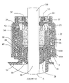
- FIG. 6 is a cross-sectional view through a through-fitting 230 .
- FIGS. 7A , 7 B, 7 C and 7 D show other views of through-fitting 230 .
- Through-fitting 230 provides both strain relief for cable C 1 and seals against the entry of moisture at the point where cable C 1 enters box 200 .
- a through-fitting 230 may be used in other contexts such as points where cables, tubes, or the like, pass into boxes, through bulk heads or the like.
- Through-fitting 230 comprises a seal 270 , which may comprise an o-ring.
- O-ring 270 is compressed against a flange 272 which surrounds an opening 274 through which cable C 1 enters box 200 .
- a compression member 276 bears a slanting annular face 278 .
- face 278 compresses o-ring 270 inwardly against cable C 1 and also compresses o-ring 270 against surface 272 , thereby providing a seal around cable C 1 .
- compression member 276 is clamped against box 200 by means of screws 285 which pass through holes 279 . In the illustrated embodiment, the screws are received in threaded bosses 280 on box 200 .
- Through-fitting 230 includes a well 282 on the inside of o-ring 270 .
- Well 282 may be filled with grease to provide additional sealing around cable C 1 .
- Clamping members 284 cover off the top end of well 282 and additionally clamp against cable C 1 to provide strain relief.
- clamping members 284 are each generally semi-circular and have a central channel 287 for receiving cable C 1 .
- Clamping members 284 are received in a pan-shaped depression 286 having a flat bottom 286 A and a sloping side wall 286 B. As shown in FIG. 7C , clamping members 284 are initially spaced apart from one enough to permit cable C 1 to be passed between them.
- Clamping members 284 are forced downwardly into depression 286 by, for example, screws 285 , clamps or the like. As this is done, the outer surfaces of clamping members 284 ride down sloped walls 286 B and are thereby forced against cable C 1 as shown in FIG. 7B .
- clamping members 284 are clamped down until they form a seal against surface 286 A which, as noted above, is preferably flat.
- Apertures 288 are provided for pumping grease into well 282 .
- there is more than one aperture to permit the grease being introduced to displace air within well 282 . This facilitates at least substantially completely filling well 282 around cable C 1 with grease.
- Clamping members 284 preferably include projections, ribs or bumps which dig at least slightly into the sheathing of cable C 1 so as to provide strain relief.
- Terminals 290 are mounted on a plate 292 which fits inside box 200 .
- FIGS. 8 , 9 , and 10 are respectively a front perspective view, back perspective view and top plan view of plate 292 .
- FIGS. 8 and 9 show plate 292 without terminals 290 .
- FIG. 11 shows the interior of a box 200 according to one embodiment of the invention.
- the conductors of cable C 1 enter box 200 and extend to terminals 290 which are positioned at spaced apart locations in a ring surrounding cable C 1 .
- Terminals 290 may be numbered for reference.
- the individual pairs of conductors C 1 -A exit from cable C 1 and are connected to terminals 290 on the underside of plate 292 .
- plate 292 preferably includes indicia including numbers or letters which identify individual sets of terminals 290 .
- plate 292 includes ridges, lines, grooves, or the like which visually segregate terminals 290 into groups.
- One group of terminals 290 may be associated with each through-fitting 240 .
- terminals 290 are grouped together to provide three sets of two terminals 290 adjacent each ingress point where a cable C 2 can be received into box 200 .
- Plate 292 preferably provides channels 294 by way of which cables C 1 -A can be routed to each group of terminals 290 .
- Channels 294 may, for example, be provided by indentations in the lower surface of plate 292 .
- FIG. 11A shows a partially cutaway view of a box 200 which illustrates how conductors C 1 -A can be carried through channels 294 beneath plate 292 to make electrical connections to the undersides of terminals 290 .
- Plate 292 preferably makes a tight contact with base 213 of box 200 . This closes off the top of the grease cavities 166 of through-fittings 240 (see FIG. 6 ).
- Plate 292 includes an aperture 296 for each incoming cable C 2 (see FIGS. 8 and 9 ). Each aperture 296 is preferably a relatively tight fit to the expected cable C 2 so that there is not too much of a tendency for excess grease to be extruded from cavities 166 through aperture 296 around cable C 2 .
- grounding ring 298 provides a grounding ring 298 (see FIGS. 11 and 12 ).
- Grounding ring 298 is connected to a ground conductor, which is typically a shield, of cable C 1 by a strap 298 A. Strap 298 A may be integral with grounding ring 298 .
- a number of grounding terminals 299 are provided on grounding ring 298 . Grounding terminals 299 are preferably located adjacent through-fittings 240 (see FIG. 6 ) to permit grounding of cables C 2 .
- FIG. 12 illustrates a possible means of connection to the ground conductor of cable C 1 .
- This structure may be used where cable C 1 has a shield which surrounds the conductors of cable C 1 .
- This connection is known in the trade as a “bullet bond”.
- Curved metal conductors 300 and 301 which match the curvature of sheath S are placed inside and outside sheath S respectively.
- a bolt 302 is connected to conductor 300 .
- Bolt 302 passes through an aperture in shielding S and also passes through an aperture in strap 298 A.
- a nut 303 clamps conductor 300 tightly to shield S and also provides a good electrical contact with strap 298 A.
- the bullet bond may be installed by slitting sheath S and peeling back a portion of sheath S to permit the conductors to be moved away to allow the insertion of member 300 .
- the conductors and other portions of cable C 1 have been cut away to provide a view of member 300 .
- FIG. 13 shows a box 200 according to the invention in which a cable C 2 has been installed.
- Cable C 2 protrudes through aperture 296 into the interior of box 200 .
- a section of the sheath of cable C 2 is stripped away to expose the shielding conductor which, in the illustrated embodiment, surrounds the conductors of cable C 2 .
- FIG. 6 shows grounding clamp 308 in side view.
- a ground clamp 308 is clamped onto cable C 2 to make electrical contact with the sheath of cable C 2 .
- the inward end of ground clamp 308 has a slot which receives one of ground terminals 299 .
- a nut (not shown) on the ground terminal 299 can then clamp the ground clamp 308 against grounding conductor 298 to provide a good ground connection for cable C 2 .
- Individual conductors C 2 -A from cable C 2 can be attached to selected ones of terminals 290 .
- Hooks 310 may be provided for neatly storing conductors out of the way.
- Ridges 293 (see FIG. 8 ) on plate 292 prevent grounding clamp 308 from twisting to one side or the other after grounding clamp 308 is installed.
- a junction box 200 as described above provides a convenient way for connections to be made from the conductors of cable C 1 to the conductors of individual cables C 2 . Furthermore, the box provides a convenient point at which tests may be made and signals may be sampled to located broken conductors or other defects which interfere with the operation of a system which includes conductors of cable C 1 and/or C 2 .
- FIG. 14 shows a sealing o-ring 320 which assists in providing a seal between top 214 and base 213 of box 200 when box 200 is closed.
- O-ring 320 is received between the wall of base 213 and an interface 322 of top 214 .
- o-ring 320 may be received between an interrupted flange 324 and a number of protrusions 326 .
- This construction permits base 213 to be injection-molded in a relatively straightforward manner while providing retaining means for o-ring 320 both above and below.
- Each location at which there is a projection 326 corresponds to a gap 324 A in flange 324 .
- lid 214 when top 214 is closed, interface 322 compresses o-ring 320 inwardly against base 213 .
- lid 214 has a ramped surface 328 located inwardly from surface 322 . When top 214 is fully closed, ramped surface 328 wedges inside the upper edge of base 213 and urges it outwardly, thereby insuring that a seal will not be lost by excessive inward deflection of the edge of base 213 .
- Hinges 216 should be configured so that they do not interfere with the fitting of top 214 onto base 213 . Hinges 216 preferably permit top 214 to float slightly so that it can find its own position in respect of base 213 .
- FIG. 15 is a sectional view through a portion of the interface between top 214 and base 213 which shows ramped surface 328 providing support to the top edge of base 213 when box 200 is closed.
- FIG. 15 also shows a cross-section through a hinge 216 which has a pin 330 which is free to float somewhat relative to top 214 .
- the main portions of box 200 including top 214 and base 213 may be made from a suitable rigid material.
- the material is preferably flame-retardant.
- these components may be injection-molded from a suitable plastic such as PVC, polycarbonate or the like.
- junction boxes 40 and 200 There are various advantages to junction boxes 40 and 200 which are described above.
- One advantage is that they are quite compact, although the volume of either of these junction boxes may be made as large as required, within practical limits.
- Another advantage is that all cables come out of the same side of the box. This is beneficial because it facilitates pulling box 40 or 200 out of a vault or other underground enclosure through what can sometimes be a relatively small opening. It can be appreciated that the design of box 200 , in particular, permits organized wiring and also permits new cables C 2 to be readily added.
- a suitable connector may be provided on the end of cable C 1 for joining cable C 1 to another cable or a piece of equipment.
Abstract
Description
-
- a tab 40 (See
FIG. 1A ) located to blockcap 20 from being screwed down untiltab 40 has been broken off or bent out of the way; - a
clip 42, as shown for example inFIG. 2 , which clips aroundstub 12 belowcap 20 and blocks cap 20 from being screwed down untilclip 42 has been removed.Clip 42 has a graspingtab 43 and a pair ofarms stub 12 whencap 20 is in the unscrewed position shown inFIG. 1A ; and/or, - an adhesive
sticker spanning cap 20 and some adjacent structure, such asstub 12.
- a tab 40 (See
-
- The number of conductors in cable C1 and C2 may vary.
-
Box 200 could be round, as illustrated, or some other shape, such as rectangular, square, octagonal, etc. To enable sealing ofbox 200 in the manner described above with an o-ring 320, it is preferable thatbox 200 be either round or, at least, have rounded corners. - Through-
fittings 40 may comprise another mechanism for automatically injecting grease from a chamber as they are tightened onto a cable or the like. For example,FIG. 16 shows a through-fitting 400 which has acap 420 which bears against apiston 421.Piston 421 is located in a cylinder 422 which is filled with an extrudable sealant such as grease. Screwing downcap 420 displacespiston 421 and thereby causes grease to be extruded from cylinder 422 intobore 416 through apassage 423. A through-fitting of the type shown inFIG. 16 will typically include seals, cable strain reliefs and the like which are not shown inFIG. 16 . - The foregoing description mentions through-fittings and junction boxes which include various components and sub-assemblies. These various components and sub-assemblies do not all need to be used together. They may be used individually, or in combination with each other, or in combination with other elements not disclosed herein.
- The invention is not limited to junction boxes for telephone lines.
- The through-fittings described above, particularly through-fitting 10 may provide good enough sealing that, for some applications, grease is not necessary.
Accordingly, the scope of the invention is to be construed in accordance with the substance defined by the following claims.
Claims (19)
Priority Applications (1)
| Application Number | Priority Date | Filing Date | Title |
|---|---|---|---|
| US11/079,232 US7062851B2 (en) | 2001-10-12 | 2005-03-15 | Through-fittings and below grade junction boxes equipped with same |
Applications Claiming Priority (5)
| Application Number | Priority Date | Filing Date | Title |
|---|---|---|---|
| CA2,359,125 | 2001-10-12 | ||
| CA2359125 | 2001-10-12 | ||
| US10/270,139 US6730849B2 (en) | 2001-10-12 | 2002-10-15 | Through-fittings and below grade junction boxes equipped with same |
| US10/774,444 US6894225B2 (en) | 2001-10-12 | 2004-02-10 | Through-fittings and below grade junction boxes equipped with same |
| US11/079,232 US7062851B2 (en) | 2001-10-12 | 2005-03-15 | Through-fittings and below grade junction boxes equipped with same |
Related Parent Applications (1)
| Application Number | Title | Priority Date | Filing Date |
|---|---|---|---|
| US10/774,444 Division US6894225B2 (en) | 2001-10-12 | 2004-02-10 | Through-fittings and below grade junction boxes equipped with same |
Publications (2)
| Publication Number | Publication Date |
|---|---|
| US20050161247A1 US20050161247A1 (en) | 2005-07-28 |
| US7062851B2 true US7062851B2 (en) | 2006-06-20 |
Family
ID=4170259
Family Applications (3)
| Application Number | Title | Priority Date | Filing Date |
|---|---|---|---|
| US10/270,139 Expired - Fee Related US6730849B2 (en) | 2001-10-12 | 2002-10-15 | Through-fittings and below grade junction boxes equipped with same |
| US10/774,444 Expired - Fee Related US6894225B2 (en) | 2001-10-12 | 2004-02-10 | Through-fittings and below grade junction boxes equipped with same |
| US11/079,232 Expired - Fee Related US7062851B2 (en) | 2001-10-12 | 2005-03-15 | Through-fittings and below grade junction boxes equipped with same |
Family Applications Before (2)
| Application Number | Title | Priority Date | Filing Date |
|---|---|---|---|
| US10/270,139 Expired - Fee Related US6730849B2 (en) | 2001-10-12 | 2002-10-15 | Through-fittings and below grade junction boxes equipped with same |
| US10/774,444 Expired - Fee Related US6894225B2 (en) | 2001-10-12 | 2004-02-10 | Through-fittings and below grade junction boxes equipped with same |
Country Status (1)
| Country | Link |
|---|---|
| US (3) | US6730849B2 (en) |
Cited By (12)
| Publication number | Priority date | Publication date | Assignee | Title |
|---|---|---|---|---|
| US20100213326A1 (en) * | 2009-02-24 | 2010-08-26 | Sioux Chief Mfg. Co., Inc. | Hanger connector for flexible tubing |
| US8622092B1 (en) | 2005-11-09 | 2014-01-07 | Sioux Chief Mfg. Co., Inc. | Pipe connection member for connecting a pipe to a pair of parallel brackets |
| US20160248179A1 (en) * | 2015-02-20 | 2016-08-25 | Corning Optical Communications Rf Llc | Cable or conduit connector with jacket retention feature |
| US9768565B2 (en) | 2012-01-05 | 2017-09-19 | Corning Optical Communications Rf Llc | Quick mount connector for a coaxial cable |
| US9859631B2 (en) | 2011-09-15 | 2018-01-02 | Corning Optical Communications Rf Llc | Coaxial cable connector with integral radio frequency interference and grounding shield |
| US9882320B2 (en) | 2015-11-25 | 2018-01-30 | Corning Optical Communications Rf Llc | Coaxial cable connector |
| US9905959B2 (en) | 2010-04-13 | 2018-02-27 | Corning Optical Communication RF LLC | Coaxial connector with inhibited ingress and improved grounding |
| US9912105B2 (en) | 2012-10-16 | 2018-03-06 | Corning Optical Communications Rf Llc | Coaxial cable connector with integral RFI protection |
| US9991651B2 (en) | 2014-11-03 | 2018-06-05 | Corning Optical Communications Rf Llc | Coaxial cable connector with post including radially expanding tabs |
| US10211547B2 (en) | 2015-09-03 | 2019-02-19 | Corning Optical Communications Rf Llc | Coaxial cable connector |
| US10290958B2 (en) | 2013-04-29 | 2019-05-14 | Corning Optical Communications Rf Llc | Coaxial cable connector with integral RFI protection and biasing ring |
| US10396508B2 (en) | 2013-05-20 | 2019-08-27 | Corning Optical Communications Rf Llc | Coaxial cable connector with integral RFI protection |
Families Citing this family (19)
| Publication number | Priority date | Publication date | Assignee | Title |
|---|---|---|---|---|
| US6818826B2 (en) * | 2002-11-22 | 2004-11-16 | Olympus Corporation | Fixing structure of signal cable |
| JP4326448B2 (en) * | 2004-10-25 | 2009-09-09 | 矢崎総業株式会社 | Wire harness extraction structure |
| WO2006094317A1 (en) * | 2005-03-03 | 2006-09-08 | Spaeth Helmuth | Protected cables |
| SE533541C2 (en) * | 2009-02-04 | 2010-10-19 | Roxtec Ab | Lubrication of a pipe or cable entry |
| SE535015C2 (en) * | 2009-02-04 | 2012-03-13 | Roxtec Ab | Compressible seal or bushing and sealing system |
| SE533818C2 (en) * | 2009-02-04 | 2011-01-25 | Roxtec Ab | Eccentric part of a pipe or cable entry |
| GB2479874A (en) * | 2010-04-26 | 2011-11-02 | Cable Man Products Ltd | Barrier connector sleeve |
| DE102010019600B4 (en) * | 2010-05-05 | 2012-04-26 | Tyco Electronics Amp Gmbh | sealing element |
| CN101847852B (en) * | 2010-05-17 | 2012-10-10 | 昆山光翼光伏科技有限公司 | Three-layer sealed wiring structure |
| TWM392470U (en) * | 2010-06-22 | 2010-11-11 | Ks Terminals Inc | Water-proof junction box and water-proof connector assembly |
| JP5790492B2 (en) * | 2011-12-28 | 2015-10-07 | 住友電装株式会社 | Wire fixing member |
| DE102012005043A1 (en) * | 2012-03-15 | 2013-09-19 | Phoenix Contact Gmbh & Co. Kg | Electric wall duct for solar systems |
| US9054445B2 (en) | 2013-03-14 | 2015-06-09 | Tyco Electronics Corporation | Electrical connectors and methods for using same |
| US20150138785A1 (en) * | 2013-11-15 | 2015-05-21 | Osram Sylvania Inc. | Enclosure with grommetless strain relief |
| US10404048B2 (en) * | 2013-11-26 | 2019-09-03 | Commscope Technologies Llc | Adapter for sealing cover for electrical interconnections |
| JP6340036B2 (en) * | 2016-06-07 | 2018-06-06 | 矢崎総業株式会社 | Exterior end cap and wire harness |
| CN105958425B (en) * | 2016-07-08 | 2018-07-10 | 深圳市沃尔核材股份有限公司 | A kind of cable branch joint |
| NL2020036B1 (en) * | 2017-12-07 | 2019-06-19 | Leia B V | CABLE ENCLOSURE AND METHOD FOR CONNECTING A FIRST CABLE END AND A SECOND CABLE END |
| CN112700934A (en) * | 2020-12-18 | 2021-04-23 | 深圳供电局有限公司 | Insulating sealing cap structure |
Citations (6)
| Publication number | Priority date | Publication date | Assignee | Title |
|---|---|---|---|---|
| US3103376A (en) | 1958-08-19 | 1963-09-10 | Earl E Howe | Steering suspension |
| US4515991A (en) * | 1982-04-22 | 1985-05-07 | Bicc Public Limited Company | Electric cable glands |
| US4549037A (en) * | 1982-09-30 | 1985-10-22 | Thomas & Betts Corporation | Environmentally sealed cable connector |
| US4692561A (en) | 1985-09-26 | 1987-09-08 | Commander Electrical Materials, Inc. | Cable connector |
| US6421905B1 (en) * | 1996-11-08 | 2002-07-23 | Istvan Feher | Method of making a coupling for a composite hose |
| US6890006B2 (en) * | 2000-07-21 | 2005-05-10 | Société d'Exploitation des Procédés Maréchal (SEPM) | Device for axially retaining a cylindrical element and more particularly a cable |
Family Cites Families (1)
| Publication number | Priority date | Publication date | Assignee | Title |
|---|---|---|---|---|
| US3584900A (en) * | 1968-09-18 | 1971-06-15 | Sno Trik Co | High-pressure sealing and gripping device |
-
2002
- 2002-10-15 US US10/270,139 patent/US6730849B2/en not_active Expired - Fee Related
-
2004
- 2004-02-10 US US10/774,444 patent/US6894225B2/en not_active Expired - Fee Related
-
2005
- 2005-03-15 US US11/079,232 patent/US7062851B2/en not_active Expired - Fee Related
Patent Citations (6)
| Publication number | Priority date | Publication date | Assignee | Title |
|---|---|---|---|---|
| US3103376A (en) | 1958-08-19 | 1963-09-10 | Earl E Howe | Steering suspension |
| US4515991A (en) * | 1982-04-22 | 1985-05-07 | Bicc Public Limited Company | Electric cable glands |
| US4549037A (en) * | 1982-09-30 | 1985-10-22 | Thomas & Betts Corporation | Environmentally sealed cable connector |
| US4692561A (en) | 1985-09-26 | 1987-09-08 | Commander Electrical Materials, Inc. | Cable connector |
| US6421905B1 (en) * | 1996-11-08 | 2002-07-23 | Istvan Feher | Method of making a coupling for a composite hose |
| US6890006B2 (en) * | 2000-07-21 | 2005-05-10 | Société d'Exploitation des Procédés Maréchal (SEPM) | Device for axially retaining a cylindrical element and more particularly a cable |
Non-Patent Citations (1)
| Title |
|---|
| Copy of official Examiner's Report from the Canadian Intellectual Property Office received on related Canadian patent application. |
Cited By (16)
| Publication number | Priority date | Publication date | Assignee | Title |
|---|---|---|---|---|
| US8622092B1 (en) | 2005-11-09 | 2014-01-07 | Sioux Chief Mfg. Co., Inc. | Pipe connection member for connecting a pipe to a pair of parallel brackets |
| US8141831B2 (en) * | 2009-02-24 | 2012-03-27 | Sioux Chief Mfg. Co., Inc. | Hanger connector for flexible tubing |
| US20100213326A1 (en) * | 2009-02-24 | 2010-08-26 | Sioux Chief Mfg. Co., Inc. | Hanger connector for flexible tubing |
| US9905959B2 (en) | 2010-04-13 | 2018-02-27 | Corning Optical Communication RF LLC | Coaxial connector with inhibited ingress and improved grounding |
| US10312629B2 (en) | 2010-04-13 | 2019-06-04 | Corning Optical Communications Rf Llc | Coaxial connector with inhibited ingress and improved grounding |
| US9859631B2 (en) | 2011-09-15 | 2018-01-02 | Corning Optical Communications Rf Llc | Coaxial cable connector with integral radio frequency interference and grounding shield |
| US9768565B2 (en) | 2012-01-05 | 2017-09-19 | Corning Optical Communications Rf Llc | Quick mount connector for a coaxial cable |
| US9912105B2 (en) | 2012-10-16 | 2018-03-06 | Corning Optical Communications Rf Llc | Coaxial cable connector with integral RFI protection |
| US10236636B2 (en) | 2012-10-16 | 2019-03-19 | Corning Optical Communications Rf Llc | Coaxial cable connector with integral RFI protection |
| US10290958B2 (en) | 2013-04-29 | 2019-05-14 | Corning Optical Communications Rf Llc | Coaxial cable connector with integral RFI protection and biasing ring |
| US10396508B2 (en) | 2013-05-20 | 2019-08-27 | Corning Optical Communications Rf Llc | Coaxial cable connector with integral RFI protection |
| US9991651B2 (en) | 2014-11-03 | 2018-06-05 | Corning Optical Communications Rf Llc | Coaxial cable connector with post including radially expanding tabs |
| US10033122B2 (en) * | 2015-02-20 | 2018-07-24 | Corning Optical Communications Rf Llc | Cable or conduit connector with jacket retention feature |
| US20160248179A1 (en) * | 2015-02-20 | 2016-08-25 | Corning Optical Communications Rf Llc | Cable or conduit connector with jacket retention feature |
| US10211547B2 (en) | 2015-09-03 | 2019-02-19 | Corning Optical Communications Rf Llc | Coaxial cable connector |
| US9882320B2 (en) | 2015-11-25 | 2018-01-30 | Corning Optical Communications Rf Llc | Coaxial cable connector |
Also Published As
| Publication number | Publication date |
|---|---|
| US6894225B2 (en) | 2005-05-17 |
| US20030070829A1 (en) | 2003-04-17 |
| US20050161247A1 (en) | 2005-07-28 |
| US20040154820A1 (en) | 2004-08-12 |
| US6730849B2 (en) | 2004-05-04 |
Similar Documents
| Publication | Publication Date | Title |
|---|---|---|
| US7062851B2 (en) | Through-fittings and below grade junction boxes equipped with same | |
| US4079193A (en) | Central office cable splice enclosure | |
| RU2186449C2 (en) | Hole packing for object and container | |
| US7442884B2 (en) | Sealing member for enclosures | |
| US5561269A (en) | Enclosure for spliced coaxial cables | |
| US3504099A (en) | Electrical connections and insulating boot therefor | |
| US5210374A (en) | Terminal housing for buried communication lines | |
| US6111201A (en) | Cable splice closure | |
| US5836791A (en) | Modular telecommunications terminal block | |
| US4039742A (en) | Waterproof cable splice enclosure kit | |
| US4451696A (en) | Toolless splice sealant device | |
| EP0749641B1 (en) | Sealing arrangement | |
| EP0740380B1 (en) | Cable splice enclosure | |
| US4423918A (en) | Re-enterable service wire splice closure | |
| KR100684024B1 (en) | Cable closure and method of enclosing a cable | |
| US5567174A (en) | Water tight grease filled connector with strain relief | |
| US4839473A (en) | Waterproof electrical splice enclosure | |
| US5235134A (en) | Sealed reenterable splice enclosure | |
| CN102474039A (en) | Sealing member | |
| US3725580A (en) | Protective cable splice assembly and method | |
| US5331114A (en) | Method and apparatus to pressure seal cable splices | |
| CA2407915C (en) | Through-fittings and below grade junction boxes equipped with same | |
| US5266743A (en) | Seal for an electric cable having an insulating sheath wrapped by exposed electrical conductors and method for sealing the electric cable to a surrounding enclosure | |
| GB2338119A (en) | Pothead | |
| EP0787372B1 (en) | Modular telecommunications terminal block |
Legal Events
| Date | Code | Title | Description |
|---|---|---|---|
| AS | Assignment |
Owner name: PRIMEX MANUFACTURING LTD., CANADA Free format text: ASSIGNMENT OF ASSIGNORS INTEREST;ASSIGNOR:KOESSLER, JUERGEN;REEL/FRAME:017303/0112 Effective date: 20060220 |
|
| FPAY | Fee payment |
Year of fee payment: 4 |
|
| FPAY | Fee payment |
Year of fee payment: 8 |
|
| AS | Assignment |
Owner name: VANGUARD PLASTICS LTD., CANADA Free format text: MERGER;ASSIGNORS:ARIZONA MOLD CORPORATION;PREMO PLASTICS ENGINEERING LTD.;VANGUARD PLASTICS LTD.;REEL/FRAME:032055/0553 Effective date: 20090401 Owner name: ARIZONA MOLD CORPORATION, CANADA Free format text: MERGER;ASSIGNORS:PRIMEX MANUFACTURING LTD.;ARIZONA MOLD CORPORATION;REEL/FRAME:032055/0455 Effective date: 20090401 Owner name: VPL ENTERPRISES LTD., CANADA Free format text: CHANGE OF NAME;ASSIGNOR:VANGUARD PLASTICS LTD.;REEL/FRAME:032127/0177 Effective date: 20090401 Owner name: PRIMEX MANUFACTURING LTD., CANADA Free format text: CHANGE OF NAME;ASSIGNOR:VPL ENTERPRISES LTD.;REEL/FRAME:032127/0195 Effective date: 20130401 |
|
| FEPP | Fee payment procedure |
Free format text: MAINTENANCE FEE REMINDER MAILED (ORIGINAL EVENT CODE: REM.) |
|
| LAPS | Lapse for failure to pay maintenance fees |
Free format text: PATENT EXPIRED FOR FAILURE TO PAY MAINTENANCE FEES (ORIGINAL EVENT CODE: EXP.) |
|
| STCH | Information on status: patent discontinuation |
Free format text: PATENT EXPIRED DUE TO NONPAYMENT OF MAINTENANCE FEES UNDER 37 CFR 1.362 |
|
| FP | Expired due to failure to pay maintenance fee |
Effective date: 20180620 |