US7057155B2 - Color sensor system with voltage offset correction - Google Patents
Color sensor system with voltage offset correction Download PDFInfo
- Publication number
- US7057155B2 US7057155B2 US10/902,674 US90267404A US7057155B2 US 7057155 B2 US7057155 B2 US 7057155B2 US 90267404 A US90267404 A US 90267404A US 7057155 B2 US7057155 B2 US 7057155B2
- Authority
- US
- United States
- Prior art keywords
- light
- signals
- filtered
- color
- unfiltered
- Prior art date
- Legal status (The legal status is an assumption and is not a legal conclusion. Google has not performed a legal analysis and makes no representation as to the accuracy of the status listed.)
- Active, expires
Links
- 238000012937 correction Methods 0.000 title description 3
- 239000011159 matrix material Substances 0.000 claims abstract description 24
- 238000000034 method Methods 0.000 claims abstract description 24
- 230000009466 transformation Effects 0.000 claims abstract description 22
- 230000003321 amplification Effects 0.000 claims abstract description 19
- 238000003199 nucleic acid amplification method Methods 0.000 claims abstract description 19
- 238000013507 mapping Methods 0.000 claims description 9
- 238000001914 filtration Methods 0.000 claims description 7
- 238000012545 processing Methods 0.000 claims description 7
- 238000001228 spectrum Methods 0.000 claims description 7
- 238000004891 communication Methods 0.000 claims 4
- 238000004364 calculation method Methods 0.000 abstract description 3
- 238000010586 diagram Methods 0.000 description 4
- 238000005259 measurement Methods 0.000 description 3
- 230000000694 effects Effects 0.000 description 2
- 239000000049 pigment Substances 0.000 description 2
- 229910008938 W—Si Inorganic materials 0.000 description 1
- 239000003990 capacitor Substances 0.000 description 1
- 238000001514 detection method Methods 0.000 description 1
- 230000008447 perception Effects 0.000 description 1
Images


Classifications
-
- G—PHYSICS
- G01—MEASURING; TESTING
- G01J—MEASUREMENT OF INTENSITY, VELOCITY, SPECTRAL CONTENT, POLARISATION, PHASE OR PULSE CHARACTERISTICS OF INFRARED, VISIBLE OR ULTRAVIOLET LIGHT; COLORIMETRY; RADIATION PYROMETRY
- G01J3/00—Spectrometry; Spectrophotometry; Monochromators; Measuring colours
- G01J3/46—Measurement of colour; Colour measuring devices, e.g. colorimeters
- G01J3/50—Measurement of colour; Colour measuring devices, e.g. colorimeters using electric radiation detectors
- G01J3/51—Measurement of colour; Colour measuring devices, e.g. colorimeters using electric radiation detectors using colour filters
- G01J3/513—Measurement of colour; Colour measuring devices, e.g. colorimeters using electric radiation detectors using colour filters having fixed filter-detector pairs
-
- G—PHYSICS
- G01—MEASURING; TESTING
- G01J—MEASUREMENT OF INTENSITY, VELOCITY, SPECTRAL CONTENT, POLARISATION, PHASE OR PULSE CHARACTERISTICS OF INFRARED, VISIBLE OR ULTRAVIOLET LIGHT; COLORIMETRY; RADIATION PYROMETRY
- G01J3/00—Spectrometry; Spectrophotometry; Monochromators; Measuring colours
- G01J3/46—Measurement of colour; Colour measuring devices, e.g. colorimeters
- G01J3/52—Measurement of colour; Colour measuring devices, e.g. colorimeters using colour charts
- G01J3/524—Calibration of colorimeters
Definitions
- FIG. 1 depicts an example of a color sensor 10 that includes a sensor module 12 and a post-sensor amplification unit 14 .
- the sensor module includes R, G, and B bandpass filters 16 , 18 , and 20 and a photodetector array 22 with individual photodetectors 24 , 26 , and 28 that are aligned with the color filters to provide color-specific responses.
- light 30 is incident on the color filters of the sensor module.
- a technique for sensing color involves detecting a portion of incident light that is not filtered by a color filter in addition to portions of the incident light that are filtered by color filters.
- the output related to the unfiltered light is used along with the outputs related to the filtered light to correct for voltage offsets that affect the amplification of the outputs.
- the output related to the unfiltered light is subtracted from the outputs related to the filtered light in a calculation of a linear transformation matrix. Subtracting the output related to the unfiltered light from the outputs related to the filtered light cancels out the offset that is carried in the outputs and produces a linear transformation matrix that incorporates offset correction.
- FIG. 1 depicts an example of a color sensor that includes a sensor module and a post-sensor amplification unit as is known in the prior art.
- FIG. 2 depicts a color sensor system that includes a photodetector that detects unfiltered light in accordance with the invention.
- FIG. 3A depicts a top view of the color filters from FIG. 2 .
- FIG. 3B depicts a top view of the photodetectors from FIG. 2 .
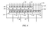
- FIG. 4 depicts how light is detected by the different photodetectors from FIG. 2 .
- FIG. 5 depicts a process flow diagram of a method for sensing color in accordance with the invention.
- FIG. 6 depicts a process flow diagram of another method for sensing color in accordance with the invention.
- Sensing color involves detecting a portion of incident light that is not filtered by a color filter in addition to portions of the incident light that are filtered by color filters.
- the output related to the unfiltered light is used along with the outputs related to the filtered light to correct for voltage offsets that effect the amplification of the outputs.
- FIG. 2 depicts an embodiment of a color sensor system 40 in accordance with the invention that detects unfiltered light in addition to filtered light.
- the color sensor system includes a sensor module 42 , a post-sensor amplification unit 44 , and a processing unit 46 .
- the sensor module 42 depicted in FIG. 2 includes color filters 48 , 50 , and 52 and a photodetector array 54 .
- the color filters consist of red (R), green (G), and blue (B) filters.
- the filters may be, for example, bandpass filters that pass light in the respective R, G, and B spectrums.
- the color filters may be formed as pigment filters that are coated on top of the photodetector array.
- the color filters can also be, for example, interference type filters or a combination of interference and pigment filters.
- the color filters filter light at color profiles that are similar to the color profiles of human perception. Although filters that pass light in the R, G, and B spectrums are described in this example, filters that pass light in other spectrums are possible.
- the photodetector array 54 depicted in FIG. 2 includes photodetectors 58 , 60 , and 62 that are aligned with the color filters 48 , 50 , and 52 to detect light that passes through the respective filters. For example, one photodetector is aligned to detect the red filtered light, one photodetector is aligned to detect the green filtered light, and one photodetector is aligned to detect the blue filtered light.
- the photodetector array also includes a photodetector 64 that is aligned to detect light that is not filtered by the color filters. The light that is not filtered by the color filter is referred to herein as “unfiltered” light.
- the photodetectors produce photocurrent in proportion to the intensity of the incident light 72 .
- the photocurrent output by the red photodetector represents the intensity of the red component of the incident light
- the photocurrent output by the green photodetector represents the intensity of the green component of the incident light
- the photocurrent output by the blue photodetector represents the intensity of the blue component of the incident light
- the photocurrent output by the unfiltered photodetector represents the total intensity of the red, green, and blue components of the incident light.
- FIG. 3A depicts a top view of the color filters 48 , 50 , and 52 identified as R, G, and B.
- FIG. 3B depicts a top view of the photodetectors 58 , 60 , 62 , and 64 identified as R, G, B, and UF, where UF stands for “unfiltered.”
- the color filters have approximately the same surface area as the corresponding photodetectors.
- the color filters do not cover the photodetector that is designated to detect unfiltered light. This allows the UF photodetector to be exposed to an unfiltered portion of the incident light.
- FIG. 4 graphically depicts the portions of the light that are detected by the photodetectors.
- light 72 is incident on the sensor module. Portions of the light are aligned with the color filters. These portions are filtered by the color filters and reach the corresponding photodetectors as filtered light.
- red filtered light 78 is detected by the red photodetector 58
- green filtered light 80 is detected by the green photodetector 60
- blue filtered light 82 is detected by the blue photodetector 62 .
- the light 84 that is incident on the unfiltered photodetector is detected by the corresponding photodetector 64 without filtering.
- the post-sensor amplification unit 44 includes amplifiers 70 that are specific to each of the photodetectors 58 , 60 , 62 , and 64 .
- amplifiers 70 that are specific to each of the photodetectors 58 , 60 , 62 , and 64 .
- the amplifiers amplify and convert photocurrent from the photodetectors into analog voltages.
- the amplifiers are transimpedence amplifiers although other types of amplifiers, such as switch capacitor type amplifiers, can be used.
- offset voltages at the input terminals of the amplifiers can skew the output voltages (i.e., V red , V green , and V blue ) and negatively affect the performance of the color sensor system.
- V red , V green , and V blue the output voltages
- V blue the output voltages
- the processing unit 46 utilizes digital processing techniques.
- the processing unit receives the analog output signals (V red , V green , V blue , and V unfiltered ) from the post-sensor amplification unit 44 , converts the output signals to digital signals, and processes the output signals to correct for voltage offsets that may exist.
- the correction for voltage offset is particularly relevant to mapping between two color spaces. Traditionally, mapping between two color spaces that have a linear relationship is accomplished using the following mapping relationship:
- the linear transformation matrix is then used in the mapping relationship to achieve a target color. Because the offset is included in the calculation of the linear transformation matrix, K, the impact of any voltage offset is corrected for.
- all of the light that is incident on the sensor module 42 may be filtered by a common filter that is located above the color filters 48 , 50 , and 52 and the photodetector array 54 . Although all of the light will be filtered to some degree in this case, the light that is not filtered by one of the color filters is still referred to herein as “unfiltered” light.
- FIG. 5 depicts a process flow diagram of a method for sensing color in accordance with the invention.
- light is filtered to pass different color spectrums.
- the filtered light and a portion of the light that is not filtered are detected.
- signals that result from the detecting are amplified.
- the amplified signals related to the filtered and unfiltered light are used to correct for voltage offsets that affect the amplifying.
- FIG. 6 depicts a process flow diagram of another method for sensing color in accordance with the invention.
- step 100 light is filtered to pass different color spectrums.
- step 102 the filtered light and a portion of the light that is not filtered are detected.
- step 104 signals that result from the detecting of the filtered and unfiltered light are amplified.
- step 106 a color-space mapping algorithm is set in response to the amplified signals related to the filtered and unfiltered light.
- the post-sensor amplification unit may be configured to provide different gain factors that can be selected in response to different lighting conditions, although this is not critical.
Abstract
Description
-
- where [TX TY TZ] represents the target color-space coordinates, where [SX SY SZ] represents the sensor color-space coordinates, and where K represents the linear transformation matrix.
As described herein, the matrix elements are provided in terms of XYZ tristimulus values. In the system ofFIG. 2 , the matrix elements SX, SY, and SZ will contain the voltage offset, which contributes to an error in the mapping between the target and sensor color spaces. In such a case, it is difficult, if not impossible, to cancel the offset values present in the XYZ elements. However, with measurements from an unfiltered photodiode, offset cancellation can be achieved by replacing all of the sensor color-space coordinates, SX, SY, and SZ, with (W−Si), where W represents the intensity of the unfiltered light as measured by the unfiltered photodetector. Making the replacement, the coordinate SX becomes (W−SX), the coordinate SY becomes (W−SY), and the coordinate SZ becomes (W−SZ). The mapping relationship is now expressed as:
- where [TX TY TZ] represents the target color-space coordinates, where [SX SY SZ] represents the sensor color-space coordinates, and where K represents the linear transformation matrix.
Claims (15)
Priority Applications (1)
| Application Number | Priority Date | Filing Date | Title |
|---|---|---|---|
| US10/902,674 US7057155B2 (en) | 2004-07-29 | 2004-07-29 | Color sensor system with voltage offset correction |
Applications Claiming Priority (1)
| Application Number | Priority Date | Filing Date | Title |
|---|---|---|---|
| US10/902,674 US7057155B2 (en) | 2004-07-29 | 2004-07-29 | Color sensor system with voltage offset correction |
Publications (2)
| Publication Number | Publication Date |
|---|---|
| US20060022121A1 US20060022121A1 (en) | 2006-02-02 |
| US7057155B2 true US7057155B2 (en) | 2006-06-06 |
Family
ID=35731061
Family Applications (1)
| Application Number | Title | Priority Date | Filing Date |
|---|---|---|---|
| US10/902,674 Active 2024-09-01 US7057155B2 (en) | 2004-07-29 | 2004-07-29 | Color sensor system with voltage offset correction |
Country Status (1)
| Country | Link |
|---|---|
| US (1) | US7057155B2 (en) |
Cited By (3)
| Publication number | Priority date | Publication date | Assignee | Title |
|---|---|---|---|---|
| US20090009831A1 (en) * | 2007-07-05 | 2009-01-08 | Hewlett-Packard Development Company, L.P. | Image Processing Method, Image Capture Device, and Computer Readable Medium |
| US20120250022A1 (en) * | 2011-04-01 | 2012-10-04 | X-Rite Europe Gmbh | Hand-Held Color Measurement Device |
| US20160356651A1 (en) * | 2015-06-02 | 2016-12-08 | X-Rite Switzerland GmbH | Sample Target for Improved Accuracy of Color Measurements and Color Measurements Using the Same |
Families Citing this family (1)
| Publication number | Priority date | Publication date | Assignee | Title |
|---|---|---|---|---|
| US20230370563A1 (en) * | 2022-05-11 | 2023-11-16 | The Boeing Company | Multi-spectral and panchromatic imaging apparatus and associated system and method |
Citations (3)
| Publication number | Priority date | Publication date | Assignee | Title |
|---|---|---|---|---|
| US5773814A (en) * | 1994-08-23 | 1998-06-30 | Hewlett-Packard Company | Sensor assembly providing gray scale and color for an optical image scanner |
| US6507159B2 (en) | 2001-03-29 | 2003-01-14 | Koninklijke Philips Electronics N.V. | Controlling method and system for RGB based LED luminary |
| US20030053157A1 (en) * | 2001-09-19 | 2003-03-20 | Jun Sakakibara | Image inputting apparatus and image forming apparatus using four-line CCD sensor |
-
2004
- 2004-07-29 US US10/902,674 patent/US7057155B2/en active Active
Patent Citations (3)
| Publication number | Priority date | Publication date | Assignee | Title |
|---|---|---|---|---|
| US5773814A (en) * | 1994-08-23 | 1998-06-30 | Hewlett-Packard Company | Sensor assembly providing gray scale and color for an optical image scanner |
| US6507159B2 (en) | 2001-03-29 | 2003-01-14 | Koninklijke Philips Electronics N.V. | Controlling method and system for RGB based LED luminary |
| US20030053157A1 (en) * | 2001-09-19 | 2003-03-20 | Jun Sakakibara | Image inputting apparatus and image forming apparatus using four-line CCD sensor |
Cited By (6)
| Publication number | Priority date | Publication date | Assignee | Title |
|---|---|---|---|---|
| US20090009831A1 (en) * | 2007-07-05 | 2009-01-08 | Hewlett-Packard Development Company, L.P. | Image Processing Method, Image Capture Device, and Computer Readable Medium |
| US8270047B2 (en) * | 2007-07-05 | 2012-09-18 | Hewlett-Packard Development Company, L.P. | Image processing method, image capture device, and computer readable medium for forming an image based on spatial frequency components |
| GB2456492B (en) * | 2007-07-05 | 2012-09-26 | Hewlett Packard Development Co | Image processing method, image capture device, and computer readable medium |
| US20120250022A1 (en) * | 2011-04-01 | 2012-10-04 | X-Rite Europe Gmbh | Hand-Held Color Measurement Device |
| US20160356651A1 (en) * | 2015-06-02 | 2016-12-08 | X-Rite Switzerland GmbH | Sample Target for Improved Accuracy of Color Measurements and Color Measurements Using the Same |
| US9823131B2 (en) * | 2015-06-02 | 2017-11-21 | X-Rite Switzerland GmbH | Sample target for improved accuracy of color measurements and color measurements using the same |
Also Published As
| Publication number | Publication date |
|---|---|
| US20060022121A1 (en) | 2006-02-02 |
Similar Documents
| Publication | Publication Date | Title |
|---|---|---|
| CN100594612C (en) | Photo detector with dark current correction | |
| US7489396B1 (en) | Spectrophotometric camera | |
| US20050200732A1 (en) | System and method for canceling dark photocurrent in a color sensor circuit | |
| MX2007006054A (en) | A signal-enhancement system for photodetector outputs. | |
| WO2002010718A3 (en) | Spectral drift and correction technique for hyperspectral imaging systems | |
| EP2201752A2 (en) | One chip image sensor for measuring vitality of subject | |
| US9627424B2 (en) | Photodiodes for ambient light sensing and proximity sensing | |
| JPH0812709B2 (en) | Bill validator | |
| JP2012507017A (en) | Spectroscopic structure and method for determining temperature values for a detector of a spectrometer | |
| JP2007172059A (en) | Paper sheet discrimination device and paper sheet processor | |
| JP2006189445A (en) | Color measurement of ambient light | |
| US8496375B2 (en) | Pyrometer adapted for detecting UV-radiation and use thereof | |
| US7057155B2 (en) | Color sensor system with voltage offset correction | |
| EP2700920B1 (en) | Light sensor system and method for processing light sensor signals | |
| US11913833B2 (en) | Optical device | |
| US20120105847A1 (en) | Spectrometric measurement system and method for compensating for veiling glare | |
| US11199450B2 (en) | Optical sensor and method for detecting electromagnetic radiation | |
| CN109738068B (en) | Method for correcting nonlinearity of response value of multispectral camera | |
| US20050219388A1 (en) | Method for noise correction for a flat-panel detector | |
| JPH0346524A (en) | Colorimeter | |
| JPS62127635A (en) | Color determining system for precisely measuring parameter inducting discoloration | |
| JP2005156243A (en) | Spectral intensity measuring device, calibration method therefor, spectral reflection characteristic measuring device, and calibration method therefor | |
| Burns et al. | Modeling colorimetric error in electronic image acquisition | |
| JP2012149917A (en) | Method for adjusting output level of measurement pixel, color sensor and virtual slide device | |
| KR100726214B1 (en) | method for calibration of picture in monitor and system for performing the same |
Legal Events
| Date | Code | Title | Description |
|---|---|---|---|
| AS | Assignment |
Owner name: AGILENT TECHNOLOGIES, INC., COLORADO Free format text: ASSIGNMENT OF ASSIGNORS INTEREST;ASSIGNORS:TAN, BOON KEAT;MANIAM, SELVAN;REEL/FRAME:015236/0762 Effective date: 20040715 |
|
| AS | Assignment |
Owner name: AVAGO TECHNOLOGIES GENERAL IP PTE. LTD.,SINGAPORE Free format text: ASSIGNMENT OF ASSIGNORS INTEREST;ASSIGNOR:AGILENT TECHNOLOGIES, INC.;REEL/FRAME:017206/0666 Effective date: 20051201 Owner name: AVAGO TECHNOLOGIES GENERAL IP PTE. LTD., SINGAPORE Free format text: ASSIGNMENT OF ASSIGNORS INTEREST;ASSIGNOR:AGILENT TECHNOLOGIES, INC.;REEL/FRAME:017206/0666 Effective date: 20051201 |
|
| STCF | Information on status: patent grant |
Free format text: PATENTED CASE |
|
| AS | Assignment |
Owner name: AVAGO TECHNOLOGIES ECBU IP (SINGAPORE) PTE. LTD.,S Free format text: ASSIGNMENT OF ASSIGNORS INTEREST;ASSIGNOR:AVAGO TECHNOLOGIES GENERAL IP (SINGAPORE) PTE. LTD.;REEL/FRAME:017675/0518 Effective date: 20060127 Owner name: AVAGO TECHNOLOGIES ECBU IP (SINGAPORE) PTE. LTD., Free format text: ASSIGNMENT OF ASSIGNORS INTEREST;ASSIGNOR:AVAGO TECHNOLOGIES GENERAL IP (SINGAPORE) PTE. LTD.;REEL/FRAME:017675/0518 Effective date: 20060127 |
|
| AS | Assignment |
Owner name: NOKIA CORPORATION, FINLAND Free format text: ASSIGNMENT OF ASSIGNORS INTEREST;ASSIGNORS:AVAGO TECHNOLOGIES GENERAL IP (SINGAPORE) PRIVATE LIMITED;AVAGO TECHNOLOGIES ECBU IP (SINGAPORE) PRIVATE LIMITED;REEL/FRAME:020986/0942;SIGNING DATES FROM 20080411 TO 20080505 |
|
| FPAY | Fee payment |
Year of fee payment: 4 |
|
| FPAY | Fee payment |
Year of fee payment: 8 |
|
| AS | Assignment |
Owner name: AVAGO TECHNOLOGIES GENERAL IP (SINGAPORE) PTE. LTD Free format text: CORRECTIVE ASSIGNMENT TO CORRECT THE ASSIGNEE NAME PREVIOUSLY RECORDED AT REEL: 017206 FRAME: 0666. ASSIGNOR(S) HEREBY CONFIRMS THE ASSIGNMENT;ASSIGNOR:AGILENT TECHNOLOGIES, INC.;REEL/FRAME:038632/0662 Effective date: 20051201 |
|
| MAFP | Maintenance fee payment |
Free format text: PAYMENT OF MAINTENANCE FEE, 12TH YEAR, LARGE ENTITY (ORIGINAL EVENT CODE: M1553) Year of fee payment: 12 |