US7041053B2 - Endoscope provided with a section for bending the endoscope - Google Patents
Endoscope provided with a section for bending the endoscope Download PDFInfo
- Publication number
- US7041053B2 US7041053B2 US10/653,946 US65394603A US7041053B2 US 7041053 B2 US7041053 B2 US 7041053B2 US 65394603 A US65394603 A US 65394603A US 7041053 B2 US7041053 B2 US 7041053B2
- Authority
- US
- United States
- Prior art keywords
- section
- bendable portion
- bending
- centering
- parameter storage
- Prior art date
- Legal status (The legal status is an assumption and is not a legal conclusion. Google has not performed a legal analysis and makes no representation as to the accuracy of the status listed.)
- Active, expires
Links
Images


Classifications
-
- A—HUMAN NECESSITIES
- A61—MEDICAL OR VETERINARY SCIENCE; HYGIENE
- A61B—DIAGNOSIS; SURGERY; IDENTIFICATION
- A61B1/00—Instruments for performing medical examinations of the interior of cavities or tubes of the body by visual or photographical inspection, e.g. endoscopes; Illuminating arrangements therefor
- A61B1/005—Flexible endoscopes
- A61B1/0051—Flexible endoscopes with controlled bending of insertion part
- A61B1/0052—Constructional details of control elements, e.g. handles
-
- A—HUMAN NECESSITIES
- A61—MEDICAL OR VETERINARY SCIENCE; HYGIENE
- A61B—DIAGNOSIS; SURGERY; IDENTIFICATION
- A61B1/00—Instruments for performing medical examinations of the interior of cavities or tubes of the body by visual or photographical inspection, e.g. endoscopes; Illuminating arrangements therefor
- A61B1/00002—Operational features of endoscopes
- A61B1/00039—Operational features of endoscopes provided with input arrangements for the user
- A61B1/00042—Operational features of endoscopes provided with input arrangements for the user for mechanical operation
-
- A—HUMAN NECESSITIES
- A61—MEDICAL OR VETERINARY SCIENCE; HYGIENE
- A61B—DIAGNOSIS; SURGERY; IDENTIFICATION
- A61B1/00—Instruments for performing medical examinations of the interior of cavities or tubes of the body by visual or photographical inspection, e.g. endoscopes; Illuminating arrangements therefor
- A61B1/00147—Holding or positioning arrangements
- A61B1/0016—Holding or positioning arrangements using motor drive units
-
- G—PHYSICS
- G02—OPTICS
- G02B—OPTICAL ELEMENTS, SYSTEMS OR APPARATUS
- G02B23/00—Telescopes, e.g. binoculars; Periscopes; Instruments for viewing the inside of hollow bodies; Viewfinders; Optical aiming or sighting devices
- G02B23/24—Instruments or systems for viewing the inside of hollow bodies, e.g. fibrescopes
- G02B23/2476—Non-optical details, e.g. housings, mountings, supports
Definitions
- the present invention relates to an endoscope inserted into a space to be inspected and used for observing the space.
- an endoscope widely used for industrial purposes comprises a flexible insertion section, which is to be inserted into a space to be inspected.
- the insertion section includes a bendable portion, and this bendable portion can be bent in the vertical direction, in the horizontal direction or in any desired direction, i.e., a combination of the vertical and horizontal directions.
- a plurality of bending-operation wires (e.g., four wires) are attached to the bendable portion.
- the proximal end of each bending-operation wire extends toward the proximal portion of the insertion section.
- An operation section is coupled to the proximal end of the insertion section.
- the operation section includes a bending-operation mechanism, and the proximal ends of the bending-operation wires are coupled to this bending-operation mechanism.
- the operation section includes an input device, such as a joystick.
- the bending-operation mechanism is driven and the bendable portion is bent, using the joystick.
- the joystick is provided with a stick whose proximal portion is pivotally supported by a pivot support.
- the stick is movable between a neutral position where it stands upright and a slanted position where it is slanted.
- signals corresponding to the direction and angle of the stick are generated.
- the joystick outputs signals when operated, and the driving motor or other structural elements of the bending-operation mechanism are driven in accordance with the output signals.
- the bending-operation wires are pulled, accordingly.
- the bending-operation wires are inserted in angle coils for protection, and in this state they are arranged in the interior of the tube of the insertion section.
- the bending-operation wires are pulled, they slide along the inner surface of the angle coils.
- the bendable portion may not be restored into its substantially linear state, which corresponds to the neutral position of the stick.
- Jpn. Pat. Appln. KOKAI Publication No. 5-15486 discloses a control means for detecting the degree to which a bendable portion is bent and controlling the time for which a driving mechanism is operated until the bendable portion is restored into the linear state.
- the degree to which the bendable portion is operated in the direction opposite to that in which it has been slanted and the time for which the driving mechanism should be operated, are determined by parameters.
- the parameters are preset for a control circuit and represent a predetermined extent.
- An endoscope according to one aspect of the present invention comprises:
- a flexible insertion section which is insertable into a space to be inspected, the insertion section including a bendable portion at a distal end thereof;
- a bending mechanism located on a proximal side of the insertion section, the bending mechanism being configured to drive the bendable portion
- a centering control section configured to control the bending mechanism such that the bendable portion is returned to a neutral position where the bendable portion is substantially linear
- a return position adjustment section configured to vary the bend of the bendable portion when the bendable portion is returned to the neutral position, the return position adjustment section operating when the centering control section is operated and determining the bend in accordance with a bending characteristic difference the bendable portion has between bending directions.
- the centering instruction input section is operated to input an instruction supplied to the centering control section.
- the centering control section controls the bending mechanism until the bendable portion returns to a neutral position where the bendable portion is substantially linear.
- the return position adjustment section varies the bend of the bendable portion when the bendable portion is returned to the neutral position.
- the return position adjustment section determines the bend in accordance with a bending characteristic difference the bendable portion has between bending directions. Accordingly, centering with high precision is enabled for each bending direction.
- the return position adjustment section includes: a recognition section configured to recognize a bending characteristic variance the bendable portion may undergo in each bending direction; and a bend-varying section configured to vary the bend the bendable portion should have when the bendable portion is returned to the neutral position, on the basis of a recognition result of the recognition section.
- the recognition section of the return position adjustment section recognizes a bending characteristic variance the bendable portion may undergo in each bending direction.
- the bend-varying section varies the bend the bendable portion should have when it is returned to the neutral position.
- the centering instruction input section of the centering control section is connected to a parameter storage section.
- the parameter storage section stores parameters based on which a centering instruction signal is generated.
- the centering instruction input section When operated, it outputs an instruction to generate a centering instruction signal and supplies it to the centering control section on the basis of a centering parameter stored in the parameter storage section.
- the operation section includes a remote control.
- the remote control includes a joystick.
- the centering instruction input section includes a centering button located near the joystick of the remote controller.
- the centering button of the centering control section is connected to a parameter storage section.
- the parameter storage section stores parameters based on which a centering instruction signal is generated. When the centering button is operated, it outputs an instruction to generate a centering instruction signal and supplies it to the centering control section on the basis of a centering parameter stored in the parameter storage section.
- the return position adjustment section includes a personal computer detachably attached to the endoscope.
- the personal computer is connected to the centering control section, and the parameters in the parameter storage section are directly changed by use of the personal computer in such a manner that the bend the bendable portion should have when it is returned to the neutral position is varied in accordance with a bending characteristic variance the bendable portion may undergo in each bending direction.
- those parameters corresponding to the directions in which the bendable portion can hardly restore its original shape are increased.
- the insertion section includes an internal channel inside, and the recognition section includes a photo-coupler configured to detect whether or not a treatment device is inserted in the internal channel.
- the bend-varying section includes two parameter storage sections that store different centering parameters.
- the centering parameters are data representing how the bendable portion should operate when it is subject to a centering operation after being bent in a given direction.
- the two parameter storage sections are specifically a first parameter storage section and a second parameter storage section.
- the bend-varying section further includes a switch section interposed between the centering control section and the two parameter storage sections.
- the first parameter storage section stores data representing how the bendable portion should operate in each bending direction where the treatment device is not inserted in the internal channel.
- the second parameter storage section stores data representing how the bendable portion should operate in each bending direction where the treatment device is inserted in the internal channel.
- the switch section operates on the basis of a recognition result of the photo-coupler and switches the first and second parameter storage sections from one to the other so as to perform a centering operation.
- An endoscope according to another aspect of the present invention comprises:
- a flexible insertion section which is insertable into a space to be inspected, the insertion section including a bendable portion at a distal end thereof;
- a bending mechanism located on a proximal side of the insertion section, the bending mechanism being configured to drive the bendable portion
- a recognition section configured to recognize a bending characteristic variance the bendable portion may undergo in each bending direction
- a bend-varying section configured to vary a bend the bendable portion should have, on the basis of a recognition result of the recognition section.
- the recognition section When the bendable portion is restored from a bent state, the recognition section recognizes a bending characteristic variance the bendable portion may undergo in each bending direction. On the basis of a recognition result of the recognition section, the bend-varying section varies the bend of the bendable portion in such a manner that centering with high precision is enabled for each bending direction.
- the recognition section includes a determination section configured to determine whether or not the bending characteristic has varied by detecting whether there is a treatment device channel through which a treatment device is inserted into the insertion section.
- the determination section determines whether or not the bending characteristic has varied. Centering with high precision is therefore enabled for each bending direction.
- the insertion section includes a treatment device channel into which the treatment device is inserted, and the recognition section includes a treatment device detecting section configured to determine whether or not the bending characteristic has varied by detecting a treatment device inserted into the treatment device channel.
- the recognition section recognizes a state where a treatment device is inserted in the treatment device channel, a state where an external channel tube is attached to the outer portion of the insertion section, or a state where forceps are inserted through the external channel tube. Based on this recognition, appropriate parameters are determined, a bending characteristic variance is determined, and centering with high precision is enabled for each bending direction.
- the bending mechanism includes operating wires used for bending the bendable portion, and a driving motor configured to pull the operating wires.
- the recognition section includes a determination section configured to make a determination based on the current value of the driving motor.
- Whether or not the bending characteristic has been varied is determined by detecting the current value of the driving motor of the bending mechanism. Based on this determination, centering with high precision is enabled for each bending direction.
- the bending mechanism includes operating wires used for bending the bendable portion, and a driving motor configured to pull the operating wires.
- the recognition section includes a determination section configured to make a determination based on the voltage applied to the driving motor.
- Whether or not the bending characteristic has been varied is determined by detecting the voltage applied to the driving motor of the bending mechanism. Based on this determination, centering with high precision is enabled for each bending direction.
- the bend-varying section includes an addition section configured to add digital signals to control signals used for bending the bendable portion.
- the digital signals are added on the basis of a recognition result of the recognition section when the bending characteristic the bendable portion has for each bending direction varies.
- the insertion section includes an attachment portion to which an external channel for insertion of the treatment device is detachably attached, and the determination section includes an external channel detector used for determining whether or not the external channel is attached to the attachment portion.
- the external channel detector includes a contact used for detecting the external channel.
- the determination section includes a photo-coupler used for determining whether the treatment device is inserted into the treatment device channel.
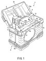
- FIG. 1 is a perspective view of the entire industrial endoscope apparatus according to the first embodiment of the present invention, the perspective view illustrating a state where the cover of an endoscope storage case is open.
- FIG. 2A is a perspective view of the endoscope storage case of the industrial endoscope apparatus of the first embodiment.
- FIG. 2B is an exploded perspective view of an assembling unit of the main body of the endoscope apparatus.
- FIG. 3 is a perspective view of an intermediate coupler of the scope section of the industrial endoscope apparatus of the first embodiment.
- FIG. 4A is a longitudinal sectional view showing the internal structure of the scope section of the industrial endoscope apparatus of the first embodiment.
- FIG. 4B is a sectional view taken along line IVB—IVB of FIG. 4A .
- FIG. 5A is a sectional view taken along line VA—VA of FIG. 4B .
- FIG. 5B is a sectional view taken along line VB—VB of FIG. 4B .
- FIG. 5C is a sectional view taken along line VC—VC of FIG. 5A .
- FIG. 6A is a longitudinal sectional view illustrating how the chain-driving sprocket of an electric bending device is assembled in the industrial endoscope apparatus of the first embodiment.
- FIG. 6B is a longitudinal sectional view illustrating a coupler between a chain and an operating wire.
- FIG. 6C is a longitudinal sectional view illustrating how the chain-driving sprocket for vertical bending is assembled.
- FIG. 6D is a longitudinal sectional view illustrating how the chain-driving sprocket for horizontal bending is assembled.
- FIG. 7 is a schematic diagram illustrating the entire control circuit of the industrial endoscope apparatus of the first embodiment.
- FIG. 8 is a cross sectional view illustrating the internal structure of the insertion section of the industrial endoscope apparatus of the first embodiment.
- FIG. 9A is an illustration showing how the bending mechanism of the industrial endoscope apparatus of the first embodiment operates.
- FIG. 9B is an illustration showing how a potentiometer operates.
- FIG. 10 is a schematic diagram showing how a personal computer is connected to a centering control section in the industrial endoscope apparatus of the first embodiment.
- FIG. 11 is a schematic diagram illustrating the entire control circuit of the industrial endoscope apparatus of the second embodiment.
- FIG. 12 is a longitudinal sectional view showing an intermediate coupler of the scope section of an industrial endoscope apparatus according to the third embodiment of the present invention.
- FIG. 13 is a schematic diagram illustrating the entire control circuit of the industrial endoscope apparatus of the third embodiment.
- FIG. 14 is a perspective view illustrating how forceps are inserted into the forceps inlet of the intermediate coupler in the industrial endoscope apparatus of the third embodiment.
- FIG. 15A is an illustration showing how the bendable portion of the industrial endoscope apparatus of the third embodiment is restored from a bent state when the forceps are not inserted in the channel.
- FIG. 15B is an illustration showing how a centering operation of the bendable portion is performed in the case of FIG. 15A .
- FIG. 15C is an illustration showing how the bendable portion is restored from a bent state when the forceps are inserted in the channel.
- FIG. 15D is an illustration showing how a centering operation of the bendable portion is performed in the case of FIG. 15C .
- FIG. 16 is a perspective view showing how a scope section provided with an external channel is coupled to a remote control in the industrial endoscope apparatus of the fourth embodiment of the present invention.
- FIG. 17 is a schematic diagram illustrating the entire control circuit of an industrial endoscope apparatus according to the fifth embodiment of the present invention.
- FIG. 18 is a schematic diagram illustrating the entire control circuit of an industrial endoscope apparatus according to the sixth embodiment of the present invention.
- FIG. 1 shows an industrial endoscope apparatus 1 of the embodiment.
- the endoscope apparatus 1 is provided with an assembling unit 2 which integrally assembles the structural elements of an endoscope, and an endoscope storage case 3 in which the assembling unit 2 is removably stored.
- the endoscope storage case 3 includes a box-shaped case main body 3 a and a cover 3 b .
- the case main body 3 a has an open upper section.
- the open upper section can be closed with the cover 3 b .
- the cover 3 b is rotatably coupled to one edge of the open upper section of the case main body 3 a by means of a hinge (not shown).
- FIG. 1 shows the state where the assembling unit 2 is stored in the endoscope storage case 3 , with the cover 3 b open.
- FIG. 2B is an exploded perspective view of the assembling unit 2 of the endoscope apparatus 1 .
- the assembling unit 2 includes a scope section 4 , a fixing unit 5 and a storage section 6 .
- the scope section 4 , the fixing unit 5 and the storage section 6 are assembled together in a detachable manner.
- the scope section 4 includes at least the following: an elongated flexible insertion section 4 a which is to be inserted into a space to be inspected; an intermediate coupler 4 b ; a universal cable 4 c ; and a base unit 4 d (i.e., a section for driving the insertion section).
- the insertion section 4 a is located at the distal end and is provided with the following: a head 4 a 1 in which an observation optical system, an illuminating optical system, etc. are incorporated; a bendable portion 4 a 2 which can be operated remotely; and an elongated flexible tube 4 a 3 .
- the bendable portion 4 a 2 is located between the head 4 a 1 and the flexible tube 4 a 3 .
- an illumination window 31 of the illuminating optical system, an observation window 32 of the observation optical system, a distal-end opening 34 of an internal channel (a treatment device passage) 33 (shown in FIG. 8 ) of the insertion section 4 a , etc. are open in the distal end face of the head 4 a 1 .
- a light guide 36 , a signal line 37 , and a plurality of angle wires (operating wires) 101 a 1 to 101 a 4 are arranged inside the insertion section 4 a .
- the light guide 36 is an optical passage through which light is transmitted to the observation window 31 .
- the signal line 37 is connected, for example, to a CCD of the observation optical system.
- the four angle wires 101 a 1 to 101 a 4 are used for bending the bendable portion 4 a 2 .
- angle wires 101 a 1 and 101 a 2 are used for vertical bending.
- the remaining angle wires 101 a 3 and 101 a 4 are used for horizontal bending.
- the bendable portion 4 a 2 of the insertion section 4 a is vertically bent by use of the two vertically-bending angle wires 101 a 1 and 101 a 2 , and is horizontally bent by use of the two horizontally-bending angle wires 101 a 3 and 101 a 4 .
- the bendable portion 4 a 2 is bent upward, downward, rightward, leftward, or in any direction desired.
- the angle wires 101 a 1 to 101 a 4 which are arranged in the internal region of the tube of the insertion section 4 a , are inserted in angle coils 101 b 1 to 101 b 4 , for protection.
- the outer circumferential surface of the insertion section 4 a is covered with an outer blade 4 a 4 .
- the intermediate coupler 4 b comprises a grip portion 4 b 1 .
- the grip portion 4 b 1 is taken hold of by the operator.
- a channel port 4 b 2 and a coupler to the distal end of the universal cable 4 c are juxtaposed.
- the channel port 4 b 2 has a forceps opening 35 (an opening at the proximal end) that communicates with an internal channel 33 .
- the internal channel 33 extends through the insertion section 4 a in the axial direction thereof.
- the coupler to the universal cable 4 c is slanted relative to the axial direction of the insertion section 4 a.
- the light guide 36 , signal line 37 and four angle wires 101 a 1 to 101 a 4 extending from the insertion section 4 a are inserted into the interior of the universal cable 4 c.
- the intermediate coupler 4 b has an insertion section-protecting rubber portion 38 .
- the insertion section-protecting rubber portion 38 serves to prevent the insertion section 4 a from being bent acutely.
- the intermediate coupler 4 b has a universal cable-protecting rubber portion 39 .
- the universal cable-protecting rubber portion 39 serves to prevent the universal cable 4 c from being bent acutely.
- the base unit 4 d comprises a unit case 4 d 1 , an electric bending device (a bending mechanism) 51 , an electric bending controller 52 for controlling the electric bending device 51 , a camera control unit (CCU) 53 (shown in FIG. 7 ), etc. These structural components are contained in the unit case 4 d 1 .
- the electric bending device 51 comprises a pulling force transmission mechanism unit 54 , and two motor units 55 a and 55 b for vertical and horizontal bending operations.
- the two motor units 55 a and 55 b are located under the pulling force transmission mechanism unit 54 .
- Motor unit 55 a comprises an output shaft 55 a 1 , a motor section 55 a 2 serving as a driving source for generating a driving force, a decelerating gear section 55 a 3 , and a potentiometer 104 a .
- motor unit 55 b comprises an output shaft 55 b 1 , a motor section 55 b 2 serving as a driving source for generating a driving force, a decelerating gear section 55 b 3 , and a potentiometer 104 b .
- the decelerating gear sections 55 a 3 and 55 b 3 are made of gear trains (e.g., spur gear trains) for transmitting the driving forces of the motor sections 55 a 2 and 55 b 2 to the output shafts 55 a l and 55 b 1 .
- the potentiometers 104 a and 104 b detect rotations of the output shafts 55 a l and 55 b 1 .
- the potentiometers 104 a and 104 b are arranged in parallel to the motor sections 55 a 2 and 55 b 2 , respectively, with the corresponding decelerating gear sections 55 a 3 and 55 b 3 being located therebetween.
- the pulling force transmission mechanism unit 54 has an upper end attached to the upper end portion of the unit case 4 d 1 .
- the proximal end of the universal cable 4 c is coupled to the upper end portion of the pulling force transmission mechanism unit 54 .
- the two motor units 55 a and 55 b are installed in the lower region of the unit case 4 d.
- the pulling force transmission mechanism unit 54 comprises a unit case 56 .
- Two pulling force transmission mechanisms 57 a and 57 b which correspond to the two bending directions of the bendable portion 4 a 2 , are provided inside the unit case 56 .
- One ( 57 a ) of the two pulling force transmission mechanisms 57 a and 57 b is shown in FIG. 5B .
- pulling force transmission mechanism 57 a includes: a sprocket 58 a fixed to the output shaft 55 a 1 of the vertically-bending motor unit 55 a ; and a chain 59 a engaged with the sprocket 58 a .
- the output shaft 55 a 1 of the motor unit 55 a is of a double shaft type.
- the motor unit 55 a has two output shafts extending in the opposite directions.
- the sprocket 58 a is attached to one of the output shafts 55 a 1 , and the potentiometer 104 a is provided at the other output shaft.
- the proximal ends of two angle wires 101 a 1 and. 101 a 2 are coupled to the two ends of the chain 59 a by means of coupling members 60 a 1 and 60 a 2 , respectively.
- the pulling force transmission mechanism 57 a shown in FIG. 5B interlocks with the motor unit 55 a , thereby providing a vertically-bending driving mechanism 51 a.
- pulling force transmission mechanism 57 b includes: a sprocket 58 b fixed to the output shaft 55 b 1 of the horizontally-bending motor unit 55 b ; and a chain 59 b engaged with the sprocket 58 b .
- the output shaft 55 b 1 of the motor unit 55 b is of a double shaft type. In other words, the motor unit 55 b has two output shafts extending in the opposite directions.
- the sprocket 58 b is attached to one of the output shafts 55 b 1 , and the potentiometer 104 b is provided at the other output shaft.
- the proximal ends of two angle wires 101 a 3 and 101 a 4 are coupled to the two ends of the chain 59 b by means of coupling members 60 a 3 and 60 a 4 , respectively.
- the pulling force transmission mechanism 57 b shown in FIG. 5A interlocks with the motor unit 55 b , thereby providing a horizontally-bending driving mechanism 51 b.
- the vertically-bending motor unit 55 a of the electric bending mechanism 51 pulls the two vertically-bending angle wires 101 a 1 and 101 a 2 .
- the horizontally-bending motor unit 55 b pulls the two horizontally-bending angle wires 101 a 3 and 101 a 4 .
- the bendable portion 4 a 2 can be bent in a vertical direction, in a horizontal direction or in any direction combined.
- the potentiometers 104 a and 104 b sense the rotated positions of the sprockets 58 a and 58 b .
- the electric bending controller 52 controls the positions of the angle wires 101 a 1 to 101 a 4 , thereby controlling the operation of bending the bendable portion 4 a 2 .
- the proximal end of the signal line 37 is connected to the camera control unit 53 .
- the distal end of the signal line 37 is connected to the CCD located inside the insertion section 4 a .
- Image data representing endoscopic observation images obtained by the CCD are converted into electric signals, and these electric signals are supplied to the camera control unit 53 through the signal line 37 .
- a light guide connector 4 d 2 is projected from an end surface of the unit case 4 d 1 of the base unit 4 d .
- the proximal end of a light guide (not shown) extending from the universal cable 4 c is coupled to the light guide connector 4 d 2 .
- a pair of attachment/detachment guides 4 d 3 namely, upper and lower attachment/detachment guides, are provided on another side surface of the unit case 4 d 1 of the base unit 4 d .
- the guides 4 d 3 extend substantially in the horizontal direction.
- the guides 4 d 3 guide the movement of the base unit 4 d .
- a plurality of fixing members 4 d 4 are projected from the above-mentioned end surface of the unit case 4 d 1 .
- the fixing members 4 d 4 come into detachable engagement with receiving portions (not shown) of the fixing unit 5 . In this manner, the base unit 4 d is fixed to the fixing unit 5 .
- the fixing unit 5 includes a power supply unit 7 , a light source device 8 and a recording unit 9 .
- the power supply unit 7 is provided with a power supply connector 7 a ( FIG. 7 ) and a power supply cover 7 b .
- a power supply cable 7 c is connected to the power supply connector 7 a .
- the power supply unit 7 is connected to a main power supply section 7 e through a switch 7 d.
- the recording unit 9 has a front panel 9 a in which a plurality of insertion slits 9 b are formed. Recording mediums, such as memory cards, are inserted through the slits 9 b .
- the recording unit 9 has a side plate 9 c in which a pair of U-shaped guide grooves 9 d are formed.
- the guide grooves extend in a substantially horizontal direction.
- the attachment/ detachment guides 4 d 3 of the base unit 4 d are brought into detachable engagement with the guide grooves 9 d .
- the guide grooves 9 d serve to guide the movement of the base unit 4 d.
- the light source device 8 comprises an outer cover 8 a .
- a lamp box provided with a light source lamp; a relay board; a lamp line board; an EL connector board; an IL switch; a ballast; a fan; etc. are contained in the outer cover 8 a.
- the outer cover 8 a of the light source device 8 is provided with a receiving portion (not shown) formed in the surface with which the base unit 4 d of the scope section 4 is brought into contact.
- the light guide connector 4 d 2 of the base unit 4 d is brought into detachable engagement with that receiving portion.
- the attachment/detachment guides 4 d 3 of the base unit 4 d of the scope section 4 are inserted in the guide grooves 9 d of the recording unit 9 .
- the attachment/detachment guides 4 d 3 are slid along the guide grooves 9 d until the base unit 4 d of the scope section 4 is detachably coupled to the light source device 8 of the fixing unit 5 .
- the light guide connector 4 d 2 of the base unit 4 d comes into detachable engagement with the receiving portion (not shown) of the light source device 8 .
- the fixing members 4 d 4 of a first connection mechanism 10 come into engagement with the receiving portion (not shown) of the fixing unit 5 .
- the light source device 8 of the fixing unit 5 and the base unit 4 d of the scope section 4 are coupled together.
- the main power supply section 7 e is electrically connected to the electric bending controller 52 and the camera control unit 53 through electric contacts.
- an LCD monitor 13 c is connected to the camera control unit 53 through the electric contacts between the base unit 4 d and the fixing unit 5 . Therefore, the endoscopic observation images obtained by the CCD of the scope section 4 are displayed on the LCD monitor 13 c.
- a remote control connector, a BNC connector and a display device 13 are provided on the upper surface of the outer cover 8 a of the light source device 8 .
- the display device 13 comprises an LCD monitor 13 c , for example.
- This LCD monitor 13 c is coupled to the top portion of a cylindrical monopod 13 a by means of a hinge mechanism 13 b .
- the hinge mechanism 13 b enables the LCD monitor 13 c to be opened or closed.
- a lamp replacement window 14 is formed in a side wall of the outer cover 8 a of the light source device 8 .
- a plurality of attachment pins 15 are projected from that side wall, for attaching the storage section 6 .
- the interior region of the storage section 6 is divided into a plurality of regions. In the case of the present embodiment, it is divided into the following two: a wide scope storage box 6 a (i.e., an insertion section storage box); and a narrow remote control storage region 6 b (i.e., a region in which a cable or the like is stored).
- a wide scope storage box 6 a i.e., an insertion section storage box
- a narrow remote control storage region 6 b i.e., a region in which a cable or the like is stored.
- the insertion section 4 a of the scope section 4 , the intermediate coupler 4 b and the universal cable 4 c are stored in the bundled state.
- the storage section 6 is provided with a storage box cover 6 c , with which the open section of the scope storage box 6 a is closed or opened.
- a remote control 16 (an input section) and a flexible cable 17 are stored in the remote control storage section 6 b .
- the base unit 4 d of the scope section 4 is operated by use of the remote control 16 .
- One end of the cable 17 is connected to the remote control 16 .
- a connector (not shown) is coupled to the other end of the cable 17 . This connector is detachably connected to the remote control connector of the fixing unit 5 .
- the storage section 6 has an attachment surface, which is to be attached to the fixing unit 5 .
- the attachment surface has pin insertion holes (not shown) at positions corresponding to the attachment pins 15 of the light source device 8 .
- the storage section 6 is detachably coupled to the side surface of the outer cover 8 a of the light source device 8 .
- the storage section 6 is provided with a scope storage box push member 21 , which is shaped substantially like “L”.
- the push member 21 is fixed to the fixing unit 5 by means of screws.
- the endoscope apparatus 1 of the present embodiment is provided with two handles 23 a and 23 b and one shoulder belt 24 , for placing the assembling case 2 into the endoscope storage case 3 or for taking it out of the case 3 .
- One ( 23 a ) of the handles is provided on the upper surface of the recording unit 9 of the fixing unit 5
- the other handle 23 b is provided on the upper surface of the outer cover 8 a of the light source device 8 .
- One end of the shoulder belt 24 is connected to the upper surface of the recording unit of the fixing unit 5
- the other end is connected to the upper surface of the outer cover 8 a of the light source device 8 .
- the assembling unit 2 has a plurality of rubber legs 25 attached to the bottom.
- a fixing member 40 is fixed to one side of the remote control 16 .
- the fixing member 40 enables detachable coupling of the intermediate coupler 4 b .
- the fixing member 40 includes a base plate 40 a , and two engagement portions 40 b and 40 c which are shaped substantially like “U”.
- the base plate 40 a is fixed to one side of the remote control 16 .
- the engagement portions 40 b and 40 c are located at the respective ends of the base plate 40 a and are substantially perpendicular to the lengthwise direction of the base plate 40 a .
- the intermediate coupler 4 b comes into detachable engagement with one side of the remote control 16 .
- the remote control 16 includes at least the following: a joystick 19 ; a power button 20 ; and a centering button 112 (e.g., a centering instruction input means).
- the joystick 19 is an instruction input means for remotely bending the bendable portion 4 a 2 of the scope section 4 in the vertical and horizontal directions.
- the power button 20 is connected to the switch 7 d of the power supply unit 7 .
- the joystick 19 has a proximal end serving as a pivotal support point 19 , and is pivotally supported.
- the remote control 16 includes a variable resistor 19 c and an A/D conversion section 106 .
- the resistance value of the variable resistor 19 c changes in accordance with the slanted direction and angle of the joystick 19 .
- the A/D conversion section 106 converts an analog voltage, which is obtained in accordance with the resistance value of the variable resistance 19 c , into a digital signal.
- the A/D conversion section 106 of the remote control 16 is electrically connected to the electric bending controller 52 of the fixing unit 5 .
- a bending instruction signal which is a digital signal obtained at the A/D conversion section 106 , is supplied to the electric bending controller 52 .
- the electric bending controller 52 includes a microcomputer 107 , a D/A converter 108 , an amplifier 109 , and an A/D conversion section 110 used for a potentiometer 110 .
- the microcomputer 107 is electrically connected to the A/D conversion section 106 of the remote control 16 and generates a digital driving signal in response to a bending instruction signal supplied from the remote control 16 .
- the digital driving signal output from the microcomputer 107 is supplied to the D/A converter 108 , by which it is converted into an analog driving signal.
- the output terminal of the D/A converter 108 is connected to the motor sections 55 a 2 and 55 b 2 through the amplifier 109 .
- the amplifier 109 amplifies the analog driving signal obtained by the D/A converter 108 , and the amplified signal is supplied to the motor sections 55 a 2 and 55 b 2 .
- the microcomputer 107 includes a CPU, a ROM (which stores a program), a RAM (which can store a program), a differential operation section 111 , and an A/D conversion section 110 for potentiometers.
- the input terminal of the A/D conversion section 110 is connected to the potentiometers 104 a and 104 b , while the output terminal of the A/D conversion section 110 is connected to the differential operation section 110 .
- the A/D conversion section 110 converts analog resistance values, which represent the rotated positions of the potentiometers 104 a and 104 b , into digital signals.
- An output signal from the A/D conversion section 110 is supplied to the differential operation section 111 .
- the differential operation section 111 subtracts the bending instruction signal of the A/D conversion section 106 of the remote control 16 from the rotation signals the potentiometers 104 a and 104 b sense with respect to the sprockets 58 a and 58 b .
- the resultant subtracted signals are used for feedback control.
- the microcomputer 107 includes a centering control section 113 and a parameter storage section 114 .
- the centering button 112 of the remote control 16 and the parameter storage section 114 are connected to the centering control section 113 .
- a parameter stored in the parameter storage section 114 represents how much the bendable portion should operate temporarily in response to an instruction supplied from the centering button 112 .
- the parameter represents how much the electric bending controller 52 should rotate the electric sprockets 58 a and 58 b .
- the rotations of the sprockets are determined based on the rotations of the output shafts 55 a 1 and 55 b 1 of the potentiometers 104 a and 104 b .
- the signals the microcomputer 107 actually uses are digital signals obtained by dividing the overall resistance of the potentiometers 104 a and 104 b by a predetermined unit value.
- the centering control section 113 In response to an instruction supplied from the centering button 112 , the centering control section 113 generates a centering instruction by use of a centering parameter stored in the parameter storage section 114 .
- the endoscope apparatus 1 of the present embodiment is provided with a personal computer 115 in place of the remote control 16 described above.
- the personal computer 115 is detachably attached to the fixing unit 5 and serves as a return position adjusting means.
- the personal computer 115 is connected to the centering control section 113 of the microcomputer 107 .
- the personal computer 115 changes parameters of the parameter storage section 114 directly. With the parameters being changed, the degree to which the bendable portion is operated in the direction opposite to that in which it has been bent, can be controlled in accordance with the bending characteristic corresponding to each direction.
- the parameter corresponding to a direction in which the bendable portion cannot be easily returned is increased in accordance with the bending characteristic the bendable portion has in that direction.
- the scope section 4 , the fixing unit 5 and the storage section 6 shown in FIG. 2B are assembled together to form the assembling unit 2 .
- This assembling unit 2 is stored in the endoscope storage case 3 shown in FIG. 2A .
- the assembling unit 2 - is stored in the endoscope storage case 3 and is then covered with the cover 3 b . In this state, the endoscope apparatus 1 is carried to a place which is in the vicinity of an object to be inspected.
- the cover 3 b of the endoscope storage 3 is opened, as shown in FIG. 1 .
- the storage box cover 6 c With the storage box cover 6 c kept open, the insertion section 4 a of the scope section 4 , the intermediate coupler 4 b and the universal cable 4 c are taken out of the scope storage box 6 a .
- the remote control 16 and the cable 17 are taken out of the remote control storage region 6 b .
- the insertion section 4 a of the scope section 4 is inserted into a space to be inspected, and the space is subject to endoscopic inspection.
- the bendable portion 4 a 2 of the scope section 4 is operated as described below by use of the joystick 19 of the remote control 16 .
- the bendable portion 4 a 2 of the scope section 4 of the present embodiment is not bent; the bendable portion 4 a 2 is held at the neutral position where its entirety is substantially linear (i.e., it is in the non-bent state where the bending angle of the bendable portion 4 a 2 is zero).
- the joystick 19 of the remote control 16 stands upright, and the chains 59 a and 59 b of the two pulling force transmission mechanisms 57 a and 57 b are neither pulled nor loosened.
- the operator moves the joystick 19 of the remote control 16 upward.
- an instruction for upward movement is supplied to the A/D conversion section 106 of the remote control 16 , for conversion into a digital signal.
- This digital signal passes through the fixing unit 5 and is then transmitted to the electric bending controller 52 .
- the microcomputer 107 checks the values of the potentiometers 104 a and 104 b and supplies data on them to the A/D conversion section 110 . After being converted into digital signals, the values of the potentiometers 104 a and 104 b are supplied to the differential operation section 111 .
- the differential operation section 111 calculates the difference components between the rotations of the sprockets 58 a and 58 b sensed by the potentiometers 104 a and 104 b and the bending instruction signals supplied from the A/D conversion section 106 of the remote control 16 . Based on this calculation, an instruction is output for bending the bendable portion 4 a 2 upward from the linear state is output.
- the A/D conversion section 106 converts the resistance of the variable resistor 19 c of the joystick 19 b into a digital signal having a 1024-gradation value in the range from “0” to “1023.”
- the A/D conversion section 110 converts the resistance values of the potentiometers 104 a and 104 b into digital signals having 1024-gradation values in the range from “0” to “1023.”
- the A/D conversion section 110 When the rotational position of the sprocket 58 a for vertical bending is neutral, the A/D conversion section 110 outputs median value “512.” Likewise, when the joystick 19 is at the neutral position, the A/D conversion section 106 outputs median value “512.” Value “0” corresponds to the maximally upward direction, and value “1023” corresponds to the maximally downward direction. Similarly, the rotational position of the sprocket 58 b for horizontal bending and the inclination angle of the joystick 19 are determined in such a manner that value “0” denotes the maximally leftward direction and value “1023” denotes the maximally rightward direction.
- the A/D conversion section 106 of the remote control 16 supplies value “0” to the electric bending controller 52 .
- the value of the A/D conversion section 110 is “512.” Therefore, the differential operation section 111 supplies the D/A converter 108 with an instruction corresponding to a differential amount of (0–512).
- the instruction is supplied through the amplifier 109 to the motor section 55 a 2 of the motor unit 55 a .
- the differential operation section 111 , the D/A converter 108 , the amplifier 109 , the motor section 55 a 2 for vertical bending, the potentiometer 104 a and the A/D conversion section 110 continue to operate until the value of the A/D conversion section 110 becomes “0.”
- the joystick 19 returns to the neutral position of itself.
- the A/D conversion section 106 of the remote control 16 outputs signal “512.”
- the differential operation section 111 subtracts signal “0” (which is an output of the A/D conversion section 110 ) from signal “512” (which is an output of the A/D conversion section 106 of the remote control 16 ). Since the subtraction performed then is (512 ⁇ 0), an instruction for moving back to the neutral position is output.
- the A/D conversion section 110 outputs “512”
- the motor section 55 a 2 is stopped, and the bending operation is thereby stopped.
- the bendable portion 4 a 2 may not completely move back to the neutral position. This is because the force corresponding to the position of the sprocket 58 a is not fully transmitted to the distal end of the bendable portion 4 a 2 , due to the frictional resistance between the angle wire 101 a and the angle coil 101 b . That is, the bendable portion 4 a 2 may be bent slightly upward then. Although the operator has moved the joystick to the neutral position by then, he or she naturally expects that the bendable portion 4 a 2 should be at the neutral position, which is not actually the case.
- the centering function is utilized for coping with this case.
- the centering function is enabled by depressing the centering button 112 of the remote control 16 .
- a centering instruction is supplied to the centering control section 113 , and a centering operation is executed using a parameter stored in the parameter storage section 114 .
- a detailed description will be given as to how this centering operation is executed.
- the bendable portion 4 a 2 may be bent slightly upward even after the joystick 19 is moved back to the neutral position.
- the centering button 112 of the remote control 16 is depressed to provide a centering instruction, based on which the bendable portion 4 a 2 is bent downward to a certain degree. If the operation of bending the bendable portion 4 a 2 is excessive, the bendable portion 4 a 2 will be in the downwardly bent state. In other words, the degree to which the bendable portion 4 a 2 is bent downward based on the centering instruction should be appropriate. This bending degree is determined by a parameter.
- the operation of bending the bendable portion 4 a 2 downward based on the centering operation is started in the state where the bendable portion 4 a 2 is bent slightly upward.
- the sprocket 58 a is slightly rotated in the direction corresponding to downward bending, and is then moved to the neutral position.
- the potentiometer 104 a is moved from the position corresponding to “512” to the position corresponding “512+30”, and is then immediately moved back to the position corresponding to “512.”
- the angle wires 101 a 1 and 101 a 2 are momentarily operated in such a way as to bend the bendable portion 4 a 2 downward.
- the angle wire 101 a 2 for downward bending is pulled, and immediately thereafter the angle wire 101 a 1 for upward bending is pulled to move the sprocket 58 a to the neutral position.
- the bendable portion 4 a 2 is momentarily bent downward and is then bent upward.
- the bendable portion 4 a 2 is bent downward, it is soon bent upward.
- the upward bending operation described above is intended to move the bendable portion 4 a 2 from “542” to “512”, and the bendable portion 4 a 2 is not operated sufficiently.
- the angle at which the bendable portion 4 a 2 remains is of a very small value.
- the downward bending operation of the bendable portion 4 a 2 is a slight operation in practice by reason of the friction between the angle wire 101 a and the angle coil 101 b . Therefore, there may be a case where the bendable portion 4 a 2 is only restored to the neutral state from the slightly bent state.
- the structural components inside the insertion section 4 a are not arranged uniformly in the radial direction. As shown in FIG. 8 , they are arranged in an eccentric fashion.
- the channel tube of the internal channel 33 which is soft and has a low restoring force, is located in the lower right region of the cross section of the insertion section 4 a .
- “having a low restoring force” means that the tube cannot be easily restored into its original state after it is bent. Hence, the tube prevents the bendable portion 4 a 2 from being restored into the original state even after the joystick 19 of the remote control 16 is moved back to the neutral position. In other words, in the example shown in FIG.
- the bendable portion 4 a 2 does not easily return to the neutral position after it is bent rightward or downward, and it returns to the neutral position with comparative ease after it is bent leftward or upward. This is attributable to the difference in the radius of curvature between the case where the bendable portion 4 a 2 is bent rightward or downward and the case where it is bent leftward or upward. Where the bendable portion 4 a 2 is bent rightward or downward, the radius of curvature of the channel tube of the internal channel 33 is of a small value, compared to the case where the bendable portion 4 a 2 is bent leftward or upward. The bendable portion 4 a 2 is hard to return to the neutral position, accordingly.
- the personal computer 115 is connected in the manner shown in FIG. 10 , and changes the values of the parameters of the parameter storage section 114 on the basis of the directions in which the bendable portion 4 a 2 can be bent. For example, the parameters corresponding to the directions in which the bendable portion 4 a 2 does not easily return are increased, such as “upward 30”, “downward 40”, “rightward 40” and “leftward 30.”
- an instruction input at the time of centering is determined in such a manner that the operation of the bendable portion 4 a 2 is slightly greater in the leftward or upward direction.
- the instruction signal transmitted to the distal end of the bendable portion 4 a 2 may be attenuated to some extent, sufficient centering of the bendable portion 4 a 2 is ensured.
- the centering operation can be executed with high accuracy without reference to the characteristics of the channel tube of the internal channel 33 .
- the endoscope apparatus 1 of the present embodiment is provided with the parameter storage section 114 configured to store variable parameters and the personal computer 115 configured to change the values of the parameters of the parameter storage section 114 .
- the personal computer 115 is connected in the manner shown in FIG. 10 in place of using the remote control 16 , and the values of the parameters stored in the parameter storage section 114 are changed directly in accordance with the four directions in which the bendable portion 4 a 2 can be bent.
- the bendable portion 4 a 2 can return accurately to the neutral position and becomes substantially linear after it is bent in any direction. In this manner, optimal centering is ensured without reference to the bending direction of the bendable portion 4 a 2 .
- FIG. 11 shows the second embodiment of the present invention.
- the second embodiment differs from the first embodiment (shown in FIGS. 1 through 10 ) in that the endoscope apparatus 1 is modified as describe below.
- the remote control 16 of the second embodiment is provided with a centering parameter-changing volume 121 .
- This volume 121 serves as a return position adjusting means and controls the degree to which the bendable portion 4 a 2 is returned to the neutral position in the direction opposite to that in which it has been bent, in accordance with the bending characteristic corresponding to each direction.
- the volume 121 includes a volume 121 a for upward centering, a volume 121 b for downward centering, a volume 121 c for rightward centering and a volume 121 d for leftward centering.
- the analog signals output from these volumes 121 a – 121 d are converted into digital signals by a centering A/D conversion section 122 . After this conversion, the signals from the volumes 121 a – 121 d are sent to the centering control section 113 of the microcomputer 107 by way of the fixing unit 5 , so that the parameters of the parameter storage section 114 can be directly changed for control.
- the volumes 121 a – 121 d of the centering parameter-changing volume 121 of the remote control 16 are operated to directly change the parameters of the parameter storage section 114 .
- the degree to which the bendable portion 4 a 2 is returned to the neutral position can be optimally determined in accordance with the bending characteristic corresponding to each direction.
- the bendable portion 4 a 2 can return accurately to the neutral position and becomes substantially linear after it is bent in any direction, and optimal centering is ensured at all times.
- the second embodiment may be provided with a means for detecting the slanted direction and angle of the joystick 19 . Where such a detection means is provided, the volumes 121 a – 121 d of the centering parameter-changing volume 121 of the remote control 16 are automatically changed in accordance with results of detection of the detection means.
- the second embodiment may employ a touch panel monitor 13 c in place of the structure that changes the volumes 121 a to 121 d of the centering parameter-changing volume 121 of the remote control 16 .
- a touch panel monitor 13 c is employed, the values of the parameters of the parameter storage section 114 can be changed on the software basis by operating the menu displayed on the monitor 13 c.
- FIG. 12 through FIGS. 15A–15D show the third embodiment of the present invention.
- the third embodiment is obtained by modifying the endoscope apparatus 1 of the first embodiment (shown in FIGS. 1 through 10 ) as follows:
- the third embodiment employs a recognition means 132 for recognizing whether forceps 131 ( FIG. 14 ) are present in the channel port 4 b 2 of the intermediate coupler of the scope section 4 .
- the recognition means 132 includes photo-couplers 133 a and 133 b.
- the micro-computer 107 of the electric bending controller 52 is provided with a bend control means for controlling the bend which the bendable portion 4 a 2 should have when it is returned to the neutral position on the basis of the recognition results of the recognition means 132 .
- the bend control means includes two parameter storage sections 134 a and 134 b and a switch 135 .
- Each of the two parameter storage sections 134 a and 134 b stores centering parameters corresponding to upward, downward, rightward and leftward directions and used for performing a centering operation after the bendable portion 4 a 2 is bent in the upward, downward, rightward and leftward directions.
- the centering parameters stored in parameter storage section 134 a differ from those stored in parameter storage section 134 b .
- parameter storage section 134 a (referred to as “A” parameter storage section) stores “30”, “40”, “40” and “30” as data corresponding to upward, downward, rightward and leftward directions, respectively, and used for performing a centering operation when the forceps 131 are not inserted in the internal channel 33 .
- parameter storage section 134 b (referred to as “B” parameter storage section) stores “10”, “20”, “20” and “10” as data corresponding to upward, downward, rightward and leftward directions, respectively, and used for performing a centering operation when the forceps 131 are inserted in the internal channel 33 .
- the switch 135 is located between the centering control section 113 and the two parameter storage sections 134 a , 134 b .
- the photo-couplers 133 a and 133 b are connected to the switch 135 .
- the switch 135 performs switching between the “A” parameter storage section 133 a and the “B” parameter storage section 133 b . In this manner, these parameter storage sections are selectively used on the basis of the recognition results of the photo-couplers 133 a and 133 b , when a centering operation is performed.
- FIG. 15A shows how the bendable portion 4 a 2 will be when it is bent without inserting the forceps 131 into the internal channel 33 and then the joystick 19 is returned to the neutral position.
- FIG. 15B illustrates how a centering operation is performed from the state shown in FIG. 15A .
- the operation for moving the bendable portion 4 a 2 back to the neutral position is a combination of the following two bending operations: the downward bending operation of angle ⁇ indicated by arrow X in FIG. 15B ; and the upward bending operation indicated by arrow Y 1 and moving back the bendable portion 4 a 2 . That is, the bendable portion 4 a 2 is returned to the neutral position in the manner indicated by the solid lines in FIG. 15B .
- FIG. 15C shows how the bendable portion 4 a 2 will be when it is bent, with the forceps 131 inserted into the internal channel 33 , and then the joystick 19 is returned to the neutral position.
- FIG. 15D illustrates how a centering operation is performed from the state shown in FIG. 15C .
- the bendable portion 4 a 2 is hardly bent by reason of the resiliency of the forceps 131 , as shown in FIG. 15C .
- the angle the bendable portion 4 a 2 forms is, for example, ⁇ 2 ( ⁇ 2 ⁇ 1).
- the centering button 112 of the remote control 16 is depressed for a centering operation, the downward bending operation of angle ⁇ indicated by arrow X in FIG. 15D is first performed. It should be noted that the position corresponding to angle X is close to the neutral position in this case. Therefore, although angle ⁇ is the same as that of the case shown in FIG.
- angle ⁇ 3 is greater than that of the case shown in FIG. 15B .
- the bendable portion 4 a 2 after the bendable portion 4 a 2 is bent downward, it must be moved greatly in the upward direction, as indicated by arrow Y 2 in FIG. 15D . That means that the bendable portion 4 a 2 has to be greatly moved upward from the end position of angle X.
- the centering operation shown in FIG. 15D may result in an excessive movement of the bendable portion 4 a 2 . That is, the bendable portion 4 a 2 moves by angle ⁇ 3, as indicated by arrow Y 2 , and this results in a movement unnecessary for inspection.
- the third embodiment therefore employs the photo-couplers 133 a and 133 b to detect whether or not the forceps 131 are inserted in the internal channel 33 , and switches between the “A” parameter storage section 133 a and the “B” parameter storage section 133 b by means of the switch 135 .
- the switch 135 connects the “A” parameter storage section 133 a to the centering control section 113 .
- the switch 135 connects the “B” parameter storage section 133 b to the centering control section 113 to use parameters of small values.
- the photo-couplers 133 a and 133 b detects whether or not the forceps 131 are present in the internal channel 33 , and the switch 135 makes switching between the “A” parameter storage section 133 a and the “B” parameter storage section 133 b on the basis of the results of detection.
- the bendable portion 4 a 2 can be returned to the neutral position with an appropriate force. After being bent in a desired direction, the bendable portion 4 a 2 can be returned to the neutral position where it is substantially linear. Hence, highly precise centering effects are attained.
- the switch 135 makes switching between the “A” parameter storage section 133 a and the “B” parameter storage section 133 b .
- the centering parameter-changing volume 121 of the second embodiment may be used to directly change the values of the parameters of the parameter storage section 114 .
- the recognition section may be an electrode that is set in an electrically conductive state when the forceps 131 are inserted.
- the switch 135 makes switching between the “A” parameter storage section 133 a and the “B” parameter storage section 133 b.
- the electrode need not be exposed to the outside; it may be replaced with a non-contact switch that is turned on or off in response to the insertion-of the forceps 131 .
- the recognition means may identify a plurality of types of forceps, and parameter storage sections 114 may be provided in such a manner that they are equal in number to the types the recognition means identifies.
- switch 135 selects one of the parameter storage sections 114 , and a centering operation is based on the parameters of the selected parameter storage section 114 .
- FIG. 16 shows the fourth embodiment of the present invention.
- the fourth embodiment differs from the first embodiment ( FIGS. 1 through 10 ) in that the endoscope apparatus 1 is modified as follows:
- the insertion section 4 a contains the internal channel 33 .
- the internal channel 33 is replaced with an external channel 141 , as shown in FIG. 16 .
- This external channel 141 is attached to the insertion section 4 a and bundled together with it by means of a bundling member, such as a tape, an O ring, a binder, or the like. That is, the external channel is used as a side channel of the endoscope.
- a pair of clamping members 143 are provided on one side of the remote control 16 .
- the clamping members 143 can be opened or closed and are capable of clamping the insertion section 4 a of the scope section 4 .
- Each clamping member 143 has two concave portions on the inner surface thereof. One is a large concave portion 143 a configured to hold the insertion section 4 a of the scope section 4 , and the other is a small concave portion 143 b configured to hold the external channel 141 .
- the clamping members 143 have contacts 144 a and 144 b , for the detection of the external channel 141 .
- the contacts 144 a and 144 b are located near the small concave portions 143 b .
- the switch 135 shown in FIG. 13 performs switching.
- the contacts 144 a and 144 b of the clamping members 143 are used for determining whether or not the external channel 141 is used, and the “A” parameter storage section 133 a and the “B” parameter storage section 133 b are switched from one to the other on the basis of the determination.
- the bendable portion 4 a 2 should be bent when it is returned to the neutral position.
- the bendable portion 4 a 2 is bent in a certain direction and is then returned to the neutral position, the presence of the external channel 141 does not become a problem. That is, the bendable portion 4 a 2 can be reliably returned to the neutral position with high accuracy and becomes substantially linear without reference to the external channel 141 .
- highly precise centering effects are attained.
- the photo-couplers 133 a and 133 b shown in FIG. 12 may be used for determining whether the external channel 141 has been attached.
- FIG. 17 shows the fifth embodiment of the present invention.
- the fifth embodiment differs from the third embodiment (shown in FIG. 12 to FIGS. 15A–15D ) in that the endoscope apparatus 1 is modified as follows:
- the fifth embodiment is provided with a current sensing section 151 for sensing the currents supplied to the motor sections 55 a 2 and 55 b 2 of the electric bending device 51 .
- the current sensing section 151 is connected to a switch 135 similar to that employed in the third embodiment. When the current value sensed by the current sensing section 151 exceeds a predetermined setting value, the switch 135 switches between the two parameter storage sections 134 a and 134 b.
- the bending characteristic of the bendable portion 4 a 2 is determined by a variety of factors. These factors include not only the eccentric state of the structural components and the presence or absence of forceps but also a winding or looping movement of the insertion section 4 a . To be more specific, if the insertion section 4 a winds or loops, the friction between the angle wires 101 a and the angle coils 101 b increases. In accordance with this increase in friction, the force required for angling the angle wire 101 a also increases.
- the current sensing section 151 senses the current value of the motor sections 55 a 2 and 55 b 2 of the electric bending device 51 .
- the switch 135 switches between the two parameter storage sections 134 a and 134 b .
- the centering parameter-changing volume 121 shown in FIG. 11 may be used in this embodiment.
- the centering parameter-changing volume 121 directly changes the values of the parameters of the parameter storage section 114 connected to the centering control section 113 of the microcomputer 107 , when the current value detected by the current sensing section 151 has exceeded the predetermined setting value.
- the force required for angling angle wires may be detected based on a voltage, not a current.
- a voltage sensing section is provided to detect a voltage value applied to the motor sections 55 a 2 and 55 b 2 .
- the motor sections 55 a 2 and 55 b 2 are driven powerfully by increasing the voltage value, so that a high voltage value indicates an increase in the force required for angling angle wires.
- the switch 135 switches between the two parameter storage sections 134 a and 134 b.
- FIG. 18 shows the sixth embodiment of the present invention.
- the sixth embodiment differs from the first embodiment ( FIGS. 1 through 10 ) in that the endoscope apparatus 1 is modified as follows:
- the sixth embodiment employs photo-couplers 133 a and 133 b as a recognition means 132 for recognizing forceps 131 .
- the photo-couplers 133 a and 133 b are located at the channel port 4 b 2 of the intermediate coupler 4 b of the scope section 4 .
- the microcomputer 107 of the electric bending controller 52 is provided with an addition section 161 that adds digital signals on the basis of results of recognition of the recognition means 132 .
- the addition section 161 adds digital signals to the signals output from the A/D conversion section 106 of the remote control 16 .
- an instruction for bending the bendable portion 4 a 2 more than the instruction entered from the joystick 19 is generated, and the generated instruction is supplied to the differential operation section 111 .
- the A/D conversion section 106 of the remote control 16 outputs digital signal “300.” Since the A/D conversion section 110 outputs “512” then, a normal bending operation corresponds to (300–512). If the photo-couplers 133 a and 133 b recognize the forceps 131 , the addition section 161 adds a predetermined value ⁇ (e.g., “20” in this case).
- the bendable portion 4 a 2 is bent by (280–512).
- the bendable portion 4 a 2 is used in combination with the forceps 131 , it cannot be easily bent. This is compensated for by adding the predetermined value ⁇ mentioned above.
- the value of ⁇ varies depending upon the types of forceps 131 . Therefore, if the photo-couplers 133 a and 133 b are configured to identify a number of types of forceps 131 , the addition section 161 can prepare different values as ⁇ and add them based on the types identified.
- the recognition means 132 for recognizing the forceps 131 is not limited to the photo-couplers and may be configured in the manner described in relation to the third embodiment.
- the recognition means may be configured to recognize it, or forceps that are inserted into it.
- the sixth embodiment may be modified to detect not only the presence/absence of the channel or forceps but also a state of the insertion section 4 a of the scope section 4 , as in the fifth embodiment shown in FIG. 17 .
- the addition section 161 adds digital values in such a manner as to increase the bending angle.
- the digital signal addition means is not limited to the addition section 161 described above. It may be an addition section configured to multiply an output of the D/A converter 108 by a predetermined coefficient, or an addition section configured to enhance the amplification function of the amplifier 109 .
Abstract
Description
Claims (21)
Applications Claiming Priority (2)
| Application Number | Priority Date | Filing Date | Title |
|---|---|---|---|
| JP2002-261748 | 2002-09-06 | ||
| JP2002261748A JP4169549B2 (en) | 2002-09-06 | 2002-09-06 | Endoscope |
Publications (2)
| Publication Number | Publication Date |
|---|---|
| US20040049097A1 US20040049097A1 (en) | 2004-03-11 |
| US7041053B2 true US7041053B2 (en) | 2006-05-09 |
Family
ID=31986384
Family Applications (1)
| Application Number | Title | Priority Date | Filing Date |
|---|---|---|---|
| US10/653,946 Active 2024-05-19 US7041053B2 (en) | 2002-09-06 | 2003-09-04 | Endoscope provided with a section for bending the endoscope |
Country Status (2)
| Country | Link |
|---|---|
| US (1) | US7041053B2 (en) |
| JP (1) | JP4169549B2 (en) |
Cited By (23)
| Publication number | Priority date | Publication date | Assignee | Title |
|---|---|---|---|---|
| US20050054899A1 (en) * | 2003-05-13 | 2005-03-10 | Olympus Corporation | Endoscope apparatus |
| US20070225556A1 (en) * | 2006-03-23 | 2007-09-27 | Ethicon Endo-Surgery, Inc. | Disposable endoscope devices |
| US20090048488A1 (en) * | 2005-05-24 | 2009-02-19 | Olympus Medical Systems Corp. | Endoscope |
| US20090192524A1 (en) * | 2006-06-29 | 2009-07-30 | Intuitive Surgical, Inc. | Synthetic representation of a surgical robot |
| US20090326318A1 (en) * | 2008-06-27 | 2009-12-31 | Intuitive Surgical, Inc. | Medical robotic system providing an auxilary view including range of motion limitations for articulatable instruments extending out of a distal end of an entry guide |
| US20090326556A1 (en) * | 2008-06-27 | 2009-12-31 | Intuitive Surgical, Inc. | Medical robotic system providing computer generated auxiliary views of a camera instrument for controlling the positioning and orienting of its tip |
| US20090326553A1 (en) * | 2008-06-27 | 2009-12-31 | Intuitive Surgical, Inc. | Medical robotic system providing an auxiliary view of articulatable instruments extending out of a distal end of an entry guide |
| US20110065994A1 (en) * | 2009-03-18 | 2011-03-17 | Fujifilm Corporation | Endoscope |
| US20110112361A1 (en) * | 2009-11-06 | 2011-05-12 | Olympus Corporation | Endoscope device |
| US20110202068A1 (en) * | 2010-02-12 | 2011-08-18 | Intuitive Surgical Operations, Inc. | Medical robotic system providing sensory feedback indicating a difference between a commanded state and a preferred pose of an articulated instrument |
| US8568299B2 (en) | 2006-05-19 | 2013-10-29 | Intuitive Surgical Operations, Inc. | Methods and apparatus for displaying three-dimensional orientation of a steerable distal tip of an endoscope |
| US8903546B2 (en) | 2009-08-15 | 2014-12-02 | Intuitive Surgical Operations, Inc. | Smooth control of an articulated instrument across areas with different work space conditions |
| US9084623B2 (en) | 2009-08-15 | 2015-07-21 | Intuitive Surgical Operations, Inc. | Controller assisted reconfiguration of an articulated instrument during movement into and out of an entry guide |
| US9101397B2 (en) | 1999-04-07 | 2015-08-11 | Intuitive Surgical Operations, Inc. | Real-time generation of three-dimensional ultrasound image using a two-dimensional ultrasound transducer in a robotic system |
| US9138129B2 (en) | 2007-06-13 | 2015-09-22 | Intuitive Surgical Operations, Inc. | Method and system for moving a plurality of articulated instruments in tandem back towards an entry guide |
| US9333042B2 (en) | 2007-06-13 | 2016-05-10 | Intuitive Surgical Operations, Inc. | Medical robotic system with coupled control modes |
| US9345387B2 (en) | 2006-06-13 | 2016-05-24 | Intuitive Surgical Operations, Inc. | Preventing instrument/tissue collisions |
| US9469034B2 (en) | 2007-06-13 | 2016-10-18 | Intuitive Surgical Operations, Inc. | Method and system for switching modes of a robotic system |
| US9492927B2 (en) | 2009-08-15 | 2016-11-15 | Intuitive Surgical Operations, Inc. | Application of force feedback on an input device to urge its operator to command an articulated instrument to a preferred pose |
| US9718190B2 (en) | 2006-06-29 | 2017-08-01 | Intuitive Surgical Operations, Inc. | Tool position and identification indicator displayed in a boundary area of a computer display screen |
| US9788909B2 (en) | 2006-06-29 | 2017-10-17 | Intuitive Surgical Operations, Inc | Synthetic representation of a surgical instrument |
| US10008017B2 (en) | 2006-06-29 | 2018-06-26 | Intuitive Surgical Operations, Inc. | Rendering tool information as graphic overlays on displayed images of tools |
| US10507066B2 (en) | 2013-02-15 | 2019-12-17 | Intuitive Surgical Operations, Inc. | Providing information of tools by filtering image areas adjacent to or on displayed images of the tools |
Families Citing this family (30)
| Publication number | Priority date | Publication date | Assignee | Title |
|---|---|---|---|---|
| US20050129108A1 (en) * | 2003-01-29 | 2005-06-16 | Everest Vit, Inc. | Remote video inspection system |
| US7591783B2 (en) | 2003-04-01 | 2009-09-22 | Boston Scientific Scimed, Inc. | Articulation joint for video endoscope |
| US20040199052A1 (en) | 2003-04-01 | 2004-10-07 | Scimed Life Systems, Inc. | Endoscopic imaging system |
| US7578786B2 (en) | 2003-04-01 | 2009-08-25 | Boston Scientific Scimed, Inc. | Video endoscope |
| US20050245789A1 (en) | 2003-04-01 | 2005-11-03 | Boston Scientific Scimed, Inc. | Fluid manifold for endoscope system |
| US8118732B2 (en) | 2003-04-01 | 2012-02-21 | Boston Scientific Scimed, Inc. | Force feedback control system for video endoscope |
| JP4709513B2 (en) * | 2004-08-19 | 2011-06-22 | オリンパス株式会社 | Electric bending control device |
| WO2006039511A2 (en) | 2004-09-30 | 2006-04-13 | Boston Scientific Scimed, Inc. | System and method of obstruction removal |
| US7479106B2 (en) * | 2004-09-30 | 2009-01-20 | Boston Scientific Scimed, Inc. | Automated control of irrigation and aspiration in a single-use endoscope |
| EP1799095A2 (en) | 2004-09-30 | 2007-06-27 | Boston Scientific Scimed, Inc. | Adapter for use with digital imaging medical device |
| US7241263B2 (en) | 2004-09-30 | 2007-07-10 | Scimed Life Systems, Inc. | Selectively rotatable shaft coupler |
| US8083671B2 (en) | 2004-09-30 | 2011-12-27 | Boston Scientific Scimed, Inc. | Fluid delivery system for use with an endoscope |
| WO2006039267A2 (en) | 2004-09-30 | 2006-04-13 | Boston Scientific Scimed, Inc. | Multi-functional endoscopic system for use in electrosurgical applications |
| US20060281990A1 (en) * | 2005-05-06 | 2006-12-14 | Viswanathan Raju R | User interfaces and navigation methods for vascular navigation |
| US7846107B2 (en) | 2005-05-13 | 2010-12-07 | Boston Scientific Scimed, Inc. | Endoscopic apparatus with integrated multiple biopsy device |
| US8097003B2 (en) * | 2005-05-13 | 2012-01-17 | Boston Scientific Scimed, Inc. | Endoscopic apparatus with integrated variceal ligation device |
| US8052597B2 (en) | 2005-08-30 | 2011-11-08 | Boston Scientific Scimed, Inc. | Method for forming an endoscope articulation joint |
| JP5097347B2 (en) * | 2005-12-26 | 2012-12-12 | オリンパスメディカルシステムズ株式会社 | Endoscope and endoscope system |
| US7967759B2 (en) | 2006-01-19 | 2011-06-28 | Boston Scientific Scimed, Inc. | Endoscopic system with integrated patient respiratory status indicator |
| US8888684B2 (en) | 2006-03-27 | 2014-11-18 | Boston Scientific Scimed, Inc. | Medical devices with local drug delivery capabilities |
| US7955255B2 (en) | 2006-04-20 | 2011-06-07 | Boston Scientific Scimed, Inc. | Imaging assembly with transparent distal cap |
| US8202265B2 (en) | 2006-04-20 | 2012-06-19 | Boston Scientific Scimed, Inc. | Multiple lumen assembly for use in endoscopes or other medical devices |
| JP4672031B2 (en) * | 2008-01-31 | 2011-04-20 | オリンパスメディカルシステムズ株式会社 | Medical instruments |
| EP2098159A1 (en) * | 2008-03-04 | 2009-09-09 | FUJIFILM Corporation | Endoscope |
| JP5559996B2 (en) * | 2009-07-13 | 2014-07-23 | 富士フイルム株式会社 | Endoscope device, endoscope system, and operation method of endoscope device |
| JP6012950B2 (en) * | 2011-10-14 | 2016-10-25 | オリンパス株式会社 | Bending motion system |
| JP6001217B1 (en) * | 2014-10-22 | 2016-10-05 | オリンパス株式会社 | Endoscope insertion shape observation device |
| EP3222195A1 (en) * | 2014-12-03 | 2017-09-27 | Olympus Corporation | Endoscope |
| JP2019170853A (en) * | 2018-03-29 | 2019-10-10 | オリンパス株式会社 | Touch panel device, curving control program, recording medium with the curving control program recorded, and curving control method for endoscope |
| CN113813051A (en) * | 2021-10-14 | 2021-12-21 | 西南医科大学附属医院 | Gastroenterology is with collapsible receiver of intestines and stomach mirror multilayer |
Citations (6)
| Publication number | Priority date | Publication date | Assignee | Title |
|---|---|---|---|---|
| US5159446A (en) | 1991-06-21 | 1992-10-27 | Olympus Optical Co., Ltd. | Electronic endoscope system provided with a separate camera controlling unit and motor controlling unit |
| JPH0515486A (en) | 1991-07-16 | 1993-01-26 | Olympus Optical Co Ltd | Endoscope |
| US5400769A (en) | 1991-02-18 | 1995-03-28 | Olympus Optical Co., Ltd. | Electrically bendable endoscope apparatus having controlled fixed bending speed |
| US5431645A (en) * | 1990-05-10 | 1995-07-11 | Symbiosis Corporation | Remotely activated endoscopic tools such as endoscopic biopsy forceps |
| US5658238A (en) * | 1992-02-25 | 1997-08-19 | Olympus Optical Co., Ltd. | Endoscope apparatus capable of being switched to a mode in which a curvature operating lever is returned and to a mode in which the curvature operating lever is not returned |
| US20020165430A1 (en) * | 2001-04-24 | 2002-11-07 | Olympus Optical Co., Ltd. | Centering mechanism for controlling the bending of an electrically bendable endoscope, and an endoscope system |
-
2002
- 2002-09-06 JP JP2002261748A patent/JP4169549B2/en not_active Expired - Fee Related
-
2003
- 2003-09-04 US US10/653,946 patent/US7041053B2/en active Active
Patent Citations (7)
| Publication number | Priority date | Publication date | Assignee | Title |
|---|---|---|---|---|
| US5431645A (en) * | 1990-05-10 | 1995-07-11 | Symbiosis Corporation | Remotely activated endoscopic tools such as endoscopic biopsy forceps |
| US5400769A (en) | 1991-02-18 | 1995-03-28 | Olympus Optical Co., Ltd. | Electrically bendable endoscope apparatus having controlled fixed bending speed |
| US5159446A (en) | 1991-06-21 | 1992-10-27 | Olympus Optical Co., Ltd. | Electronic endoscope system provided with a separate camera controlling unit and motor controlling unit |
| JPH0515486A (en) | 1991-07-16 | 1993-01-26 | Olympus Optical Co Ltd | Endoscope |
| US5658238A (en) * | 1992-02-25 | 1997-08-19 | Olympus Optical Co., Ltd. | Endoscope apparatus capable of being switched to a mode in which a curvature operating lever is returned and to a mode in which the curvature operating lever is not returned |
| US20020165430A1 (en) * | 2001-04-24 | 2002-11-07 | Olympus Optical Co., Ltd. | Centering mechanism for controlling the bending of an electrically bendable endoscope, and an endoscope system |
| US6551237B2 (en) * | 2001-04-24 | 2003-04-22 | Olympus Optical Co., Ltd. | Centering mechanism for controlling the bending of an electrically bendable endoscope, and an endoscope system |
Cited By (69)
| Publication number | Priority date | Publication date | Assignee | Title |
|---|---|---|---|---|
| US9232984B2 (en) | 1999-04-07 | 2016-01-12 | Intuitive Surgical Operations, Inc. | Real-time generation of three-dimensional ultrasound image using a two-dimensional ultrasound transducer in a robotic system |
| US10433919B2 (en) | 1999-04-07 | 2019-10-08 | Intuitive Surgical Operations, Inc. | Non-force reflecting method for providing tool force information to a user of a telesurgical system |
| US9101397B2 (en) | 1999-04-07 | 2015-08-11 | Intuitive Surgical Operations, Inc. | Real-time generation of three-dimensional ultrasound image using a two-dimensional ultrasound transducer in a robotic system |
| US10271909B2 (en) | 1999-04-07 | 2019-04-30 | Intuitive Surgical Operations, Inc. | Display of computer generated image of an out-of-view portion of a medical device adjacent a real-time image of an in-view portion of the medical device |
| US7285088B2 (en) * | 2003-05-13 | 2007-10-23 | Olympus Corporation | Endoscope apparatus |
| US20050054899A1 (en) * | 2003-05-13 | 2005-03-10 | Olympus Corporation | Endoscope apparatus |
| US20090048488A1 (en) * | 2005-05-24 | 2009-02-19 | Olympus Medical Systems Corp. | Endoscope |
| US8517926B2 (en) * | 2005-05-24 | 2013-08-27 | Olympus Medical Systems Corp. | Endoscope |
| US20070225556A1 (en) * | 2006-03-23 | 2007-09-27 | Ethicon Endo-Surgery, Inc. | Disposable endoscope devices |
| US10426412B2 (en) | 2006-05-19 | 2019-10-01 | Intuitive Surgical Operations, Inc. | Methods and apparatus for displaying three-dimensional orientation of a steerable distal tip of an endoscope |
| US9357901B2 (en) | 2006-05-19 | 2016-06-07 | Intuitive Surgical Operations, Inc. | Methods and apparatus for displaying three-dimensional orientation of a steerable distal tip of an endoscope |
| US8568299B2 (en) | 2006-05-19 | 2013-10-29 | Intuitive Surgical Operations, Inc. | Methods and apparatus for displaying three-dimensional orientation of a steerable distal tip of an endoscope |
| US9345387B2 (en) | 2006-06-13 | 2016-05-24 | Intuitive Surgical Operations, Inc. | Preventing instrument/tissue collisions |
| US10737394B2 (en) | 2006-06-29 | 2020-08-11 | Intuitive Surgical Operations, Inc. | Synthetic representation of a surgical robot |
| US9718190B2 (en) | 2006-06-29 | 2017-08-01 | Intuitive Surgical Operations, Inc. | Tool position and identification indicator displayed in a boundary area of a computer display screen |
| US11865729B2 (en) | 2006-06-29 | 2024-01-09 | Intuitive Surgical Operations, Inc. | Tool position and identification indicator displayed in a boundary area of a computer display screen |
| US9801690B2 (en) | 2006-06-29 | 2017-10-31 | Intuitive Surgical Operations, Inc. | Synthetic representation of a surgical instrument |
| US11638999B2 (en) | 2006-06-29 | 2023-05-02 | Intuitive Surgical Operations, Inc. | Synthetic representation of a surgical robot |
| US9789608B2 (en) | 2006-06-29 | 2017-10-17 | Intuitive Surgical Operations, Inc. | Synthetic representation of a surgical robot |
| US10008017B2 (en) | 2006-06-29 | 2018-06-26 | Intuitive Surgical Operations, Inc. | Rendering tool information as graphic overlays on displayed images of tools |
| US9788909B2 (en) | 2006-06-29 | 2017-10-17 | Intuitive Surgical Operations, Inc | Synthetic representation of a surgical instrument |
| US10773388B2 (en) | 2006-06-29 | 2020-09-15 | Intuitive Surgical Operations, Inc. | Tool position and identification indicator displayed in a boundary area of a computer display screen |
| US10137575B2 (en) | 2006-06-29 | 2018-11-27 | Intuitive Surgical Operations, Inc. | Synthetic representation of a surgical robot |
| US20090192524A1 (en) * | 2006-06-29 | 2009-07-30 | Intuitive Surgical, Inc. | Synthetic representation of a surgical robot |
| US10730187B2 (en) | 2006-06-29 | 2020-08-04 | Intuitive Surgical Operations, Inc. | Tool position and identification indicator displayed in a boundary area of a computer display screen |
| US11399908B2 (en) | 2007-06-13 | 2022-08-02 | Intuitive Surgical Operations, Inc. | Medical robotic system with coupled control modes |
| US10695136B2 (en) | 2007-06-13 | 2020-06-30 | Intuitive Surgical Operations, Inc. | Preventing instrument/tissue collisions |
| US10271912B2 (en) | 2007-06-13 | 2019-04-30 | Intuitive Surgical Operations, Inc. | Method and system for moving a plurality of articulated instruments in tandem back towards an entry guide |
| US10188472B2 (en) | 2007-06-13 | 2019-01-29 | Intuitive Surgical Operations, Inc. | Medical robotic system with coupled control modes |
| US9629520B2 (en) | 2007-06-13 | 2017-04-25 | Intuitive Surgical Operations, Inc. | Method and system for moving an articulated instrument back towards an entry guide while automatically reconfiguring the articulated instrument for retraction into the entry guide |
| US9469034B2 (en) | 2007-06-13 | 2016-10-18 | Intuitive Surgical Operations, Inc. | Method and system for switching modes of a robotic system |
| US9333042B2 (en) | 2007-06-13 | 2016-05-10 | Intuitive Surgical Operations, Inc. | Medical robotic system with coupled control modes |
| US9138129B2 (en) | 2007-06-13 | 2015-09-22 | Intuitive Surgical Operations, Inc. | Method and system for moving a plurality of articulated instruments in tandem back towards an entry guide |
| US11432888B2 (en) | 2007-06-13 | 2022-09-06 | Intuitive Surgical Operations, Inc. | Method and system for moving a plurality of articulated instruments in tandem back towards an entry guide |
| US11751955B2 (en) | 2007-06-13 | 2023-09-12 | Intuitive Surgical Operations, Inc. | Method and system for retracting an instrument into an entry guide |
| US9901408B2 (en) | 2007-06-13 | 2018-02-27 | Intuitive Surgical Operations, Inc. | Preventing instrument/tissue collisions |
| US10258425B2 (en) | 2008-06-27 | 2019-04-16 | Intuitive Surgical Operations, Inc. | Medical robotic system providing an auxiliary view of articulatable instruments extending out of a distal end of an entry guide |
| US9089256B2 (en) | 2008-06-27 | 2015-07-28 | Intuitive Surgical Operations, Inc. | Medical robotic system providing an auxiliary view including range of motion limitations for articulatable instruments extending out of a distal end of an entry guide |
| US9717563B2 (en) | 2008-06-27 | 2017-08-01 | Intuitive Surgical Operations, Inc. | Medical robotic system providing an auxilary view including range of motion limitations for articulatable instruments extending out of a distal end of an entry guide |
| US11638622B2 (en) | 2008-06-27 | 2023-05-02 | Intuitive Surgical Operations, Inc. | Medical robotic system providing an auxiliary view of articulatable instruments extending out of a distal end of an entry guide |
| US8864652B2 (en) | 2008-06-27 | 2014-10-21 | Intuitive Surgical Operations, Inc. | Medical robotic system providing computer generated auxiliary views of a camera instrument for controlling the positioning and orienting of its tip |
| US11382702B2 (en) | 2008-06-27 | 2022-07-12 | Intuitive Surgical Operations, Inc. | Medical robotic system providing an auxiliary view including range of motion limitations for articulatable instruments extending out of a distal end of an entry guide |
| US20090326553A1 (en) * | 2008-06-27 | 2009-12-31 | Intuitive Surgical, Inc. | Medical robotic system providing an auxiliary view of articulatable instruments extending out of a distal end of an entry guide |
| US9516996B2 (en) | 2008-06-27 | 2016-12-13 | Intuitive Surgical Operations, Inc. | Medical robotic system providing computer generated auxiliary views of a camera instrument for controlling the position and orienting of its tip |
| US20090326318A1 (en) * | 2008-06-27 | 2009-12-31 | Intuitive Surgical, Inc. | Medical robotic system providing an auxilary view including range of motion limitations for articulatable instruments extending out of a distal end of an entry guide |
| US10368952B2 (en) | 2008-06-27 | 2019-08-06 | Intuitive Surgical Operations, Inc. | Medical robotic system providing an auxiliary view including range of motion limitations for articulatable instruments extending out of a distal end of an entry guide |
| US20090326556A1 (en) * | 2008-06-27 | 2009-12-31 | Intuitive Surgical, Inc. | Medical robotic system providing computer generated auxiliary views of a camera instrument for controlling the positioning and orienting of its tip |
| US8523766B2 (en) * | 2009-03-18 | 2013-09-03 | Fujifilm Corporation | Endoscope |
| US20110065994A1 (en) * | 2009-03-18 | 2011-03-17 | Fujifilm Corporation | Endoscope |
| US10984567B2 (en) | 2009-03-31 | 2021-04-20 | Intuitive Surgical Operations, Inc. | Rendering tool information as graphic overlays on displayed images of tools |
| US11941734B2 (en) | 2009-03-31 | 2024-03-26 | Intuitive Surgical Operations, Inc. | Rendering tool information as graphic overlays on displayed images of tools |
| US10282881B2 (en) | 2009-03-31 | 2019-05-07 | Intuitive Surgical Operations, Inc. | Rendering tool information as graphic overlays on displayed images of tools |
| US11596490B2 (en) | 2009-08-15 | 2023-03-07 | Intuitive Surgical Operations, Inc. | Application of force feedback on an input device to urge its operator to command an articulated instrument to a preferred pose |
| US9492927B2 (en) | 2009-08-15 | 2016-11-15 | Intuitive Surgical Operations, Inc. | Application of force feedback on an input device to urge its operator to command an articulated instrument to a preferred pose |
| US10772689B2 (en) | 2009-08-15 | 2020-09-15 | Intuitive Surgical Operations, Inc. | Controller assisted reconfiguration of an articulated instrument during movement into and out of an entry guide |
| US8903546B2 (en) | 2009-08-15 | 2014-12-02 | Intuitive Surgical Operations, Inc. | Smooth control of an articulated instrument across areas with different work space conditions |
| US10959798B2 (en) | 2009-08-15 | 2021-03-30 | Intuitive Surgical Operations, Inc. | Application of force feedback on an input device to urge its operator to command an articulated instrument to a preferred pose |
| US9084623B2 (en) | 2009-08-15 | 2015-07-21 | Intuitive Surgical Operations, Inc. | Controller assisted reconfiguration of an articulated instrument during movement into and out of an entry guide |
| US10271915B2 (en) | 2009-08-15 | 2019-04-30 | Intuitive Surgical Operations, Inc. | Application of force feedback on an input device to urge its operator to command an articulated instrument to a preferred pose |
| US9956044B2 (en) | 2009-08-15 | 2018-05-01 | Intuitive Surgical Operations, Inc. | Controller assisted reconfiguration of an articulated instrument during movement into and out of an entry guide |
| US20110112361A1 (en) * | 2009-11-06 | 2011-05-12 | Olympus Corporation | Endoscope device |
| US10537994B2 (en) | 2010-02-12 | 2020-01-21 | Intuitive Surgical Operations, Inc. | Medical robotic system providing sensory feedback indicating a difference between a commanded state and a preferred pose of an articulated instrument |
| US9622826B2 (en) | 2010-02-12 | 2017-04-18 | Intuitive Surgical Operations, Inc. | Medical robotic system providing sensory feedback indicating a difference between a commanded state and a preferred pose of an articulated instrument |
| US20110202068A1 (en) * | 2010-02-12 | 2011-08-18 | Intuitive Surgical Operations, Inc. | Medical robotic system providing sensory feedback indicating a difference between a commanded state and a preferred pose of an articulated instrument |
| US8918211B2 (en) | 2010-02-12 | 2014-12-23 | Intuitive Surgical Operations, Inc. | Medical robotic system providing sensory feedback indicating a difference between a commanded state and a preferred pose of an articulated instrument |
| US10828774B2 (en) | 2010-02-12 | 2020-11-10 | Intuitive Surgical Operations, Inc. | Medical robotic system providing sensory feedback indicating a difference between a commanded state and a preferred pose of an articulated instrument |
| US11389255B2 (en) | 2013-02-15 | 2022-07-19 | Intuitive Surgical Operations, Inc. | Providing information of tools by filtering image areas adjacent to or on displayed images of the tools |
| US11806102B2 (en) | 2013-02-15 | 2023-11-07 | Intuitive Surgical Operations, Inc. | Providing information of tools by filtering image areas adjacent to or on displayed images of the tools |
| US10507066B2 (en) | 2013-02-15 | 2019-12-17 | Intuitive Surgical Operations, Inc. | Providing information of tools by filtering image areas adjacent to or on displayed images of the tools |
Also Published As
| Publication number | Publication date |
|---|---|
| JP4169549B2 (en) | 2008-10-22 |
| JP2004101737A (en) | 2004-04-02 |
| US20040049097A1 (en) | 2004-03-11 |
Similar Documents
| Publication | Publication Date | Title |
|---|---|---|
| US7041053B2 (en) | Endoscope provided with a section for bending the endoscope | |
| US7074182B2 (en) | Videoendoscope | |
| EP2151184B1 (en) | Active drive type medical apparatus | |
| US8454497B2 (en) | Endoscope apparatus and bending drive control method | |
| EP2671499B1 (en) | Endoscope | |
| US7998058B2 (en) | Endoscope system comprising endoscope to which medical instrument is attached | |
| JP5583860B2 (en) | Insertion device provided with operation input unit | |
| US8038605B2 (en) | Bending control device | |
| US7214183B2 (en) | Endoscope apparatus having an insertion channel | |
| JP4365860B2 (en) | Endoscope device | |
| EP1832224B1 (en) | Endoscope device with tiltable display | |
| US8382659B2 (en) | Endoscope apparatus and controlling method thereof comprising curving control mechanism | |
| EP2583616A1 (en) | Endoscope | |
| EP1982637B1 (en) | Endoscopic operation assisting device | |
| US20080249365A1 (en) | Endoscope and endoscopic system | |
| EP1859724B1 (en) | Electric bending endoscope device and endoscope supporting device | |
| WO2008018554A1 (en) | Operation device and operation device for endoscope | |
| EP3192426A1 (en) | Bending operation device and endoscope | |
| JPS6359329B2 (en) | ||
| JP3222190B2 (en) | Bending control device for endoscope | |
| US20150313447A1 (en) | Insertion instrument and endoscope | |
| US8717427B2 (en) | Endoscope | |
| JP5396178B2 (en) | Endoscope apparatus and endoscope system | |
| JP2761246B2 (en) | Endoscope device | |
| JP3176671B2 (en) | Electric curved endoscope device |
Legal Events
| Date | Code | Title | Description |
|---|---|---|---|
| AS | Assignment |
Owner name: OLYMPUS OPTICAL CO., LTD., JAPAN Free format text: ASSIGNMENT OF ASSIGNORS INTEREST;ASSIGNOR:MIYAKE, KIYOSHI;REEL/FRAME:014459/0207 Effective date: 20030827 |
|
| FEPP | Fee payment procedure |
Free format text: PAYOR NUMBER ASSIGNED (ORIGINAL EVENT CODE: ASPN); ENTITY STATUS OF PATENT OWNER: LARGE ENTITY |
|
| STCF | Information on status: patent grant |
Free format text: PATENTED CASE |
|
| FPAY | Fee payment |
Year of fee payment: 4 |
|
| FPAY | Fee payment |
Year of fee payment: 8 |
|
| AS | Assignment |
Owner name: OLYMPUS CORPORATION, JAPAN Free format text: CHANGE OF ADDRESS;ASSIGNOR:OLYMPUS CORPORATION;REEL/FRAME:039344/0502 Effective date: 20160401 |
|
| MAFP | Maintenance fee payment |
Free format text: PAYMENT OF MAINTENANCE FEE, 12TH YEAR, LARGE ENTITY (ORIGINAL EVENT CODE: M1553) Year of fee payment: 12 |
|
| AS | Assignment |
Owner name: OLYMPUS CORPORATION, JAPAN Free format text: CHANGE OF NAME;ASSIGNOR:OLYMPUS OPTICAL CO., LTD.;REEL/FRAME:061054/0162 Effective date: 20031001 Owner name: EVIDENT CORPORATION, JAPAN Free format text: ASSIGNMENT OF ASSIGNORS INTEREST;ASSIGNOR:OLYMPUS CORPORATION;REEL/FRAME:060766/0269 Effective date: 20220727 |