US7040630B2 - Chuck with quick change - Google Patents
Chuck with quick change Download PDFInfo
- Publication number
- US7040630B2 US7040630B2 US10/403,928 US40392803A US7040630B2 US 7040630 B2 US7040630 B2 US 7040630B2 US 40392803 A US40392803 A US 40392803A US 7040630 B2 US7040630 B2 US 7040630B2
- Authority
- US
- United States
- Prior art keywords
- jaws
- detent
- chuck
- bore
- tool shaft
- Prior art date
- Legal status (The legal status is an assumption and is not a legal conclusion. Google has not performed a legal analysis and makes no representation as to the accuracy of the status listed.)
- Expired - Fee Related
Links
Images


Classifications
-
- B—PERFORMING OPERATIONS; TRANSPORTING
- B25—HAND TOOLS; PORTABLE POWER-DRIVEN TOOLS; MANIPULATORS
- B25B—TOOLS OR BENCH DEVICES NOT OTHERWISE PROVIDED FOR, FOR FASTENING, CONNECTING, DISENGAGING OR HOLDING
- B25B23/00—Details of, or accessories for, spanners, wrenches, screwdrivers
- B25B23/0007—Connections or joints between tool parts
- B25B23/0035—Connection means between socket or screwdriver bit and tool
-
- B—PERFORMING OPERATIONS; TRANSPORTING
- B23—MACHINE TOOLS; METAL-WORKING NOT OTHERWISE PROVIDED FOR
- B23B—TURNING; BORING
- B23B31/00—Chucks; Expansion mandrels; Adaptations thereof for remote control
- B23B31/02—Chucks
- B23B31/10—Chucks characterised by the retaining or gripping devices or their immediate operating means
- B23B31/107—Retention by laterally-acting detents, e.g. pins, screws, wedges; Retention by loose elements, e.g. balls
- B23B31/1071—Retention by balls
-
- B—PERFORMING OPERATIONS; TRANSPORTING
- B23—MACHINE TOOLS; METAL-WORKING NOT OTHERWISE PROVIDED FOR
- B23B—TURNING; BORING
- B23B31/00—Chucks; Expansion mandrels; Adaptations thereof for remote control
- B23B31/02—Chucks
- B23B31/10—Chucks characterised by the retaining or gripping devices or their immediate operating means
- B23B31/12—Chucks with simultaneously-acting jaws, whether or not also individually adjustable
- B23B31/1207—Chucks with simultaneously-acting jaws, whether or not also individually adjustable moving obliquely to the axis of the chuck in a plane containing this axis
- B23B31/1238—Jaws movement actuated by a nut with conical screw-thread
-
- B—PERFORMING OPERATIONS; TRANSPORTING
- B23—MACHINE TOOLS; METAL-WORKING NOT OTHERWISE PROVIDED FOR
- B23B—TURNING; BORING
- B23B31/00—Chucks; Expansion mandrels; Adaptations thereof for remote control
- B23B31/02—Chucks
- B23B31/10—Chucks characterised by the retaining or gripping devices or their immediate operating means
- B23B31/12—Chucks with simultaneously-acting jaws, whether or not also individually adjustable
- B23B31/1207—Chucks with simultaneously-acting jaws, whether or not also individually adjustable moving obliquely to the axis of the chuck in a plane containing this axis
- B23B31/1253—Jaws movement actuated by an axially movable member
-
- B—PERFORMING OPERATIONS; TRANSPORTING
- B25—HAND TOOLS; PORTABLE POWER-DRIVEN TOOLS; MANIPULATORS
- B25B—TOOLS OR BENCH DEVICES NOT OTHERWISE PROVIDED FOR, FOR FASTENING, CONNECTING, DISENGAGING OR HOLDING
- B25B23/00—Details of, or accessories for, spanners, wrenches, screwdrivers
- B25B23/0007—Connections or joints between tool parts
-
- B—PERFORMING OPERATIONS; TRANSPORTING
- B23—MACHINE TOOLS; METAL-WORKING NOT OTHERWISE PROVIDED FOR
- B23B—TURNING; BORING
- B23B2231/00—Details of chucks, toolholder shanks or tool shanks
- B23B2231/38—Keyless chucks for hand tools
-
- B—PERFORMING OPERATIONS; TRANSPORTING
- B23—MACHINE TOOLS; METAL-WORKING NOT OTHERWISE PROVIDED FOR
- B23B—TURNING; BORING
- B23B2231/00—Details of chucks, toolholder shanks or tool shanks
- B23B2231/44—Nose pieces
-
- Y—GENERAL TAGGING OF NEW TECHNOLOGICAL DEVELOPMENTS; GENERAL TAGGING OF CROSS-SECTIONAL TECHNOLOGIES SPANNING OVER SEVERAL SECTIONS OF THE IPC; TECHNICAL SUBJECTS COVERED BY FORMER USPC CROSS-REFERENCE ART COLLECTIONS [XRACs] AND DIGESTS
- Y10—TECHNICAL SUBJECTS COVERED BY FORMER USPC
- Y10S—TECHNICAL SUBJECTS COVERED BY FORMER USPC CROSS-REFERENCE ART COLLECTIONS [XRACs] AND DIGESTS
- Y10S279/00—Chucks or sockets
- Y10S279/902—Keyless type socket
-
- Y—GENERAL TAGGING OF NEW TECHNOLOGICAL DEVELOPMENTS; GENERAL TAGGING OF CROSS-SECTIONAL TECHNOLOGIES SPANNING OVER SEVERAL SECTIONS OF THE IPC; TECHNICAL SUBJECTS COVERED BY FORMER USPC CROSS-REFERENCE ART COLLECTIONS [XRACs] AND DIGESTS
- Y10—TECHNICAL SUBJECTS COVERED BY FORMER USPC
- Y10S—TECHNICAL SUBJECTS COVERED BY FORMER USPC CROSS-REFERENCE ART COLLECTIONS [XRACs] AND DIGESTS
- Y10S279/00—Chucks or sockets
- Y10S279/904—Quick change socket
-
- Y—GENERAL TAGGING OF NEW TECHNOLOGICAL DEVELOPMENTS; GENERAL TAGGING OF CROSS-SECTIONAL TECHNOLOGIES SPANNING OVER SEVERAL SECTIONS OF THE IPC; TECHNICAL SUBJECTS COVERED BY FORMER USPC CROSS-REFERENCE ART COLLECTIONS [XRACs] AND DIGESTS
- Y10—TECHNICAL SUBJECTS COVERED BY FORMER USPC
- Y10T—TECHNICAL SUBJECTS COVERED BY FORMER US CLASSIFICATION
- Y10T279/00—Chucks or sockets
- Y10T279/17—Socket type
- Y10T279/17008—Multiple alternative
-
- Y—GENERAL TAGGING OF NEW TECHNOLOGICAL DEVELOPMENTS; GENERAL TAGGING OF CROSS-SECTIONAL TECHNOLOGIES SPANNING OVER SEVERAL SECTIONS OF THE IPC; TECHNICAL SUBJECTS COVERED BY FORMER USPC CROSS-REFERENCE ART COLLECTIONS [XRACs] AND DIGESTS
- Y10—TECHNICAL SUBJECTS COVERED BY FORMER USPC
- Y10T—TECHNICAL SUBJECTS COVERED BY FORMER US CLASSIFICATION
- Y10T279/00—Chucks or sockets
- Y10T279/17—Socket type
- Y10T279/17128—Self-grasping
- Y10T279/17136—Yielding grasping jaws
- Y10T279/17145—Ball or roller
-
- Y—GENERAL TAGGING OF NEW TECHNOLOGICAL DEVELOPMENTS; GENERAL TAGGING OF CROSS-SECTIONAL TECHNOLOGIES SPANNING OVER SEVERAL SECTIONS OF THE IPC; TECHNICAL SUBJECTS COVERED BY FORMER USPC CROSS-REFERENCE ART COLLECTIONS [XRACs] AND DIGESTS
- Y10—TECHNICAL SUBJECTS COVERED BY FORMER USPC
- Y10T—TECHNICAL SUBJECTS COVERED BY FORMER US CLASSIFICATION
- Y10T279/00—Chucks or sockets
- Y10T279/17—Socket type
- Y10T279/17128—Self-grasping
- Y10T279/17171—One-way-clutch type
- Y10T279/17188—Side detent
- Y10T279/17196—Ball or roller
-
- Y—GENERAL TAGGING OF NEW TECHNOLOGICAL DEVELOPMENTS; GENERAL TAGGING OF CROSS-SECTIONAL TECHNOLOGIES SPANNING OVER SEVERAL SECTIONS OF THE IPC; TECHNICAL SUBJECTS COVERED BY FORMER USPC CROSS-REFERENCE ART COLLECTIONS [XRACs] AND DIGESTS
- Y10—TECHNICAL SUBJECTS COVERED BY FORMER USPC
- Y10T—TECHNICAL SUBJECTS COVERED BY FORMER US CLASSIFICATION
- Y10T279/00—Chucks or sockets
- Y10T279/17—Socket type
- Y10T279/17615—Obliquely guided reciprocating jaws
- Y10T279/17623—Threaded sleeve and jaw
- Y10T279/17632—Conical sleeve
-
- Y—GENERAL TAGGING OF NEW TECHNOLOGICAL DEVELOPMENTS; GENERAL TAGGING OF CROSS-SECTIONAL TECHNOLOGIES SPANNING OVER SEVERAL SECTIONS OF THE IPC; TECHNICAL SUBJECTS COVERED BY FORMER USPC CROSS-REFERENCE ART COLLECTIONS [XRACs] AND DIGESTS
- Y10—TECHNICAL SUBJECTS COVERED BY FORMER USPC
- Y10T—TECHNICAL SUBJECTS COVERED BY FORMER US CLASSIFICATION
- Y10T279/00—Chucks or sockets
- Y10T279/17—Socket type
- Y10T279/17761—Side detent
- Y10T279/17811—Reciprocating sleeve
-
- Y—GENERAL TAGGING OF NEW TECHNOLOGICAL DEVELOPMENTS; GENERAL TAGGING OF CROSS-SECTIONAL TECHNOLOGIES SPANNING OVER SEVERAL SECTIONS OF THE IPC; TECHNICAL SUBJECTS COVERED BY FORMER USPC CROSS-REFERENCE ART COLLECTIONS [XRACs] AND DIGESTS
- Y10—TECHNICAL SUBJECTS COVERED BY FORMER USPC
- Y10T—TECHNICAL SUBJECTS COVERED BY FORMER US CLASSIFICATION
- Y10T279/00—Chucks or sockets
- Y10T279/29—More than one set of gripping means
-
- Y—GENERAL TAGGING OF NEW TECHNOLOGICAL DEVELOPMENTS; GENERAL TAGGING OF CROSS-SECTIONAL TECHNOLOGIES SPANNING OVER SEVERAL SECTIONS OF THE IPC; TECHNICAL SUBJECTS COVERED BY FORMER USPC CROSS-REFERENCE ART COLLECTIONS [XRACs] AND DIGESTS
- Y10—TECHNICAL SUBJECTS COVERED BY FORMER USPC
- Y10T—TECHNICAL SUBJECTS COVERED BY FORMER US CLASSIFICATION
- Y10T408/00—Cutting by use of rotating axially moving tool
- Y10T408/94—Tool-support
- Y10T408/95—Tool-support with tool-retaining means
- Y10T408/953—Clamping jaws
Definitions
- the present invention relates generally to chucks for use with drills or with electric or pneumatic power drivers. More particularly, the present invention relates to a chuck of the keyless type which may be tightened or loosened by hand or by actuation of the driver motor.
- twist drills are the most common tools used with such drivers
- the tools may also comprise screw drivers, nut drivers, burrs, mounted grinding stones, and other cutting or abrading tools. Since the tools may have shanks of varying diameter or may have a polygonal cross section, the device is usually provided with a chuck that is adjustable over a relatively wide range. The chuck may be attached to the driver by a threaded or tapered bore.
- chucks have been developed in the art.
- three jaws spaced circumferentially approximately 120° apart from each other are constrained by angularly disposed passageways in a body attached to the drive shaft.
- the chuck is configured so that rotation of the body in one direction with respect to a constrained nut forces the jaws into or away from the gripping relationship with a tool shank.
- Such a chuck may be keyless if it can be tightened or loosened by manual rotation. Examples of such chucks are disclosed in U.S. Pat. Nos. 5,125,673 and 5,193,824, commonly assigned to the present assignee and the entire disclosures of which are incorporated by reference herein.
- Various configurations of keyless chucks are known in the art and are desirable for variety of applications.
- One exemplary such device includes a body with a central bore that receives a bit having a polygonal cross section.
- the body includes a groove extending transversely across the body and opening into the axial bore.
- the bit includes an annular groove at its rear end.
- a wire is disposed in the body groove so that when the bit is pushed into the bore, the bit pushes the wire radially outward.
- the wire is, however, biased radially inward.
- the chuck body includes a stem portion extending from its rear.
- the stem may be received in the bore of a three-jawed oblique chuck as described above so that the quick-change chuck is secured to the drill by the three-jawed chuck.
- Another quick-change device is disclosed in U.S. Pat. No. 5,947,484, the disclosure of which is incorporated by reference herein.
- the present invention recognizes and addresses the foregoing considerations, and others, of prior art constructions and methods.
- FIG. 1 is front plan view, partly in section, of a chuck in accordance with an embodiment of the present invention
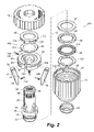
- FIG. 2 is an exploded view of the chuck as in FIG. 1 ;
- FIG. 3 is a partial sectional view of a chuck in accordance with an embodiment of the present invention.
- FIG. 4 is a partial sectional view of a chuck in accordance with an embodiment of the present invention.
- FIG. 5 is a partial perspective view of a jaw for use in a chuck in accordance with an embodiment of the present invention engaging a bit;
- FIG. 6 is a partial sectional view of a chuck in accordance with an embodiment of the present invention.
- FIG. 7 is a plan view, in section, of a chuck in accordance with an embodiment of the present invention.
- FIG. 8 is a partial sectional view of the chuck as in FIG. 7 ;
- FIG. 9 is a partial sectional view of a chuck in accordance with an embodiment of the present invention.
- a chuck 10 in accordance with the present invention has a central longitudinal axis depicted by the dashed line designated at 12 .
- Chuck 10 includes a front sleeve 14 , a rear sleeve 16 , and a plurality of jaws 18 .
- a body 20 is generally cylindrical in shape and comprises a nose or forward section 22 and a tail or rearward section 24 .
- An axial bore 26 is formed in the nose section and is somewhat larger than the largest tool shank that the chuck is designed to accommodate.
- body 20 may be formed from steel bar stock or any other suitable material.
- Body 20 defines a threaded bore 28 in its tail section.
- Bore 28 is of a standard size to mate with the drive shaft of a powered or hand driver (not shown). While a threaded bore 28 is illustrated, such bore could be replaced with a tapered bore of a standard size to mate with a tapered drive shaft.
- the bores 26 and 28 may communicate at a central region of body 20 .
- the central region may be formed with a socket to accept a drive bit so that the body may be screwed onto to the spindle by the bit.
- Body 20 also defines three passageways 32 to respectively accommodate the three jaws 18 .
- each passageway, and therefore each jaw is separated from each adjacent passageway by an arc of approximately 120°.
- the longitudinal axes of passageways 32 and jaws 18 are angled with respect to the chuck's longitudinal axis 12 but intersect the chuck axis at a common point ahead of chuck body 20 .
- Each jaw has a tool engaging face 34 that is generally parallel to axis 12 .
- Body 20 includes a thrust ring member 36 , which in a preferred embodiment forms an integral part of the body.
- the thrust ring may be a separate component from the body's main portion.
- a ledge 40 extending forward from thrust ring 36 receives a bearing assembly 42 .
- the bearing assembly includes a bearing cage 44 enclosing bearing balls 46 that forwardly bear, with respect to chuck body 20 , on a forward washer 48 and rearwardly bear on a rearward washer 50 .
- Rearward race 50 abuts a shoulder surface 52 formed between the raised and ledge portions of thrust ring 36 .
- Forward race 48 bears in an axially forward direction against a spring washer 122 that in turn bears against a shoulder 54 of sleeve 14 .
- Bearing assembly 42 may comprise any suitable construction, for example a bearing assembly of the type described in U.S. Pat. No. 5,348,318, incorporated by reference herein.
- Tail section 24 of body 20 can include a rear cylindrical portion having a knurled surface 56 thereon for receipt of rear sleeve 16 .
- the rear sleeve may be pressed onto the knurled surface, or could be retained in place by press fit without knurling or by use of a key.
- nose section 22 is beveled and is adapted to receive a nose piece 57 for restraining front sleeve 14 from forward axial movement with respect to the chuck body.
- a snap ring or other suitable mechanism may be used to axially restrain the sleeve.
- Nose piece 57 may be pressed onto nose section 22 or attached in any other suitable manner. Rearward axial movement of the sleeve on the body is prevented by thrust ring 36 through bearing assembly 42 .
- the outer circumferential surface of sleeve 14 may be knurled or may be provided with longitudinal ribs or other protrusions to enable the operator to grip it securely.
- the front and rear sleeves may be fabricated from a structural plastic such as polycarbonate, a filled polypropylene, for example glass filled polypropylene, or a blend of structural plastic materials. Other composite materials such as, for example, graphite filled polymerics could also be suitable in certain environments. Further, either sleeve may be constructed from suitable metals, such as steel. Moreover, as would be appreciated by one skilled in the art, the materials from which the chuck of the present invention is fabricated will depend on the end use of the chuck, and the above are provided by way of example only.
- An interior surface 59 of sleeve 14 defines female threads 58 .
- the threads are a modified square thread formation in an eight pitch configuration along the length of sleeve 14 . It should be understood, however, that any suitable thread shape or formation may be employed, for example including a modified buttress thread. In one preferred embodiment, the squared interface between the outer surface and the back side of thread 58 is replaced by a curved surface.
- a driving disk 60 includes a male thread 62 extending about an outer circumferential surface 64 .
- Thread 62 has the same pitch as thread 58 so that when thread 62 is received by thread 58 , relative rotation between sleeve 14 and driving disk 60 moves the driving disk axially within the sleeve.
- thread 62 may have sloped sides, for example at an approximately 5° slope, extending from surface 64 to the thread's outer diameter.
- Driving disk 60 includes three equiangularly spaced apart radial slots 106 extending entirely radially through the disk.
- Slots 106 are cylindrical in shape and may be formed by boring radially inward into the driving disk outer surface with a suitable boring tool.
- Jaw end sections 68 are formed in a cooperating semi-circular shape so that the slots 106 slideably receive the respective jaws.
- the slots allow the jaw ends to move radially as the driving disk moves the jaws between open and closed positions.
- a dry lubricant coating may be provided on the jaw ends and/or slots 106 to facilitate this movement.
- the cooperation between the jaw ends and slots 106 maintains the jaws at the proper angle with respect to the driving disk so that the jaws are maintained in alignment in the jaw passageways in the assembled chuck.
- a stop 92 is provided at the rear edge of thread 58 . When the jaws reach a fully open position, a rear edge 94 of thread 62 abuts stop 92 . This prevents further rotation of the sleeve with respect to the driving disk.
- a similar stop (not shown) is provided at the front end of thread 58 to stop a forward edge 98 of thread 62 to prevent the jaws from binding in the fully closed position when there is no tool in the chuck bore.
- Thread 62 defines one turn that extends slightly less than 360° around surface 64 of driving disk 60 .
- a gap 100 between edges 94 and 98 has an angular width greater than the width of stop 92 . This facilitates the chuck's assembly in that the driving disk may be placed directly down onto thread 58 over the stop.
- Rear sleeve 16 prevents the driving disk from disengaging from the sleeve when the chuck is in a fully open position in which rear thread edge 94 abuts stop 92 .
- Bearing assembly 42 may comprise any suitable construction.
- FIG. 2 illustrates two bearing configurations 42 a and 42 b .
- the washer that forms bearing race 48 includes radially aligned recesses 114 in the washer's rearward face so that each of bearing balls 46 are received in a respective recess 114 .
- bearing 42 b includes a first race 48 having recesses 114 defined about the radially outward edge of its rearward face.
- Opposite race 50 includes a shroud 116 extending axially forward therefrom.
- the shroud defines a plurality of spring arms 118 biased axially forward toward washer 48 so that tabs 120 defined at the distal ends of arms 118 engage respective recesses 114 .
- Driving disk 60 includes a blind bore 124 that extends radially inward from the driving disk's outer surface 64 .
- a spring 126 biases a detent ball 128 radially outward from bore 124 .
- ball 128 rides on lands 130 between the grooves of thread 58 .
- a depression 132 is formed in the lands so that ball 128 moves into the depression when the jaws' tool engaging surfaces 34 define a predefined diameter.
- the diameter is slightly less than the cross width of the a tool, preferably a multi-sided tool, which the chuck is to receive. In one preferred embodiment, for example, the diameter is slightly less than one-quarter inch.
- Ball 128 makes a clicking sound when entering depression 132 and slightly inhibits rotation of sleeve 14 . This notifies the user that the jaws are in the predetermined position to receive the tool shank.
- a multi-sided bit 134 that is pushed into bore 26 against tool engaging surfaces 34 of jaws 18 pushes the jaws radially outward. This forces the jaws axially rearward in jaw passageways 32 , thereby pushing driving disk 60 and sleeve 14 axially rearward on body 20 against the force of spring washer 122 .
- spring 122 applies a forward bias to the jaws through sleeve 14 and driving disk 60 to retain the tool in the bore.
- the tool's flat sides 125 , and their interfaces 127 generally prevent the tool's rotation within the bore.
- bore 124 opens radially inward from driving disk 60 .
- Depression 132 is located at a predetermined position in body tail section 24 .
- bore 124 is located in sleeve 14 and opens radially inward to a groove of thread 58 .
- Spring 126 biases a detent ball or pin 133 into the thread at predetermined position on the thread so that driving disk thread 62 ( FIG. 2 ) engages pin 133 at the point where tool engaging jaw surfaces 34 ( FIG. 2 ) define the predetermined diameter. Further rotation of sleeve 14 pushes pin 133 up into bore 124 .
- an operator pulls sleeve 14 axially rearward against the force of spring 122 . This pulls driving disk 60 , and therefore jaws 18 , axially rearward, thereby releasing the bit.
- each jaw 18 may define a blind bore 136 extending radially inward from its tool engaging surface 34 .
- a spring 138 biases a detent ball 140 radially inward.
- the mouth of bore 136 may be peened about its edge to create a lip that retains ball 140 in the bore.
- bit 134 moves into bore 26
- the bit's rear edge pushes ball 140 back into bore 136 .
- spring 138 pushes ball 140 into the groove, thereby positively retaining bit 134 axially in bore 26 .
- an operator pulls the bit axially forward so that the rear end of bit 134 pushes ball 140 back into bore 136 .
- a forward portion of the tool engaging surface 34 of each jaw 18 may be ground so that the tool engaging surface extends forward from a rear heel 144 defined at the rearward edge of the jaw face.
- the ground forward portion defines the predetermined diameter.
- a bore 146 is defined through thrust ring 36 .
- a spring 148 extends between a detent ball 150 and a biasing ball 152 .
- biasing ball 152 is pushed radially inward by a tapered surface 154 of an annular ring 156 attached to the inner surface of sleeve 14 .
- the bit pushes ball 150 back into bore 146 until groove 142 aligns with the bore. At this point, ball 150 moves into groove 142 to positively retain the bit.
- ring 156 also moves rearward, allowing ball 152 to ride radially outward against tapered surface 154 . This partially relieves the pressure against ball 150 , allowing the operator to more easily remove bit 134 from bore 26 .
- an operator may secure a tool, for example a bit having a circular cross-section, in chuck 10 by rotation of sleeve 14 to clamp jaws 18 onto the tool shank.
- the operator may rotate the sleeve until it reaches the predetermined position as indicated by the locator mechanism and thereafter insert and extract tools of a predetermined size against the biasing force provided by spring 122 .
- This mode of operation is particularly suited to tool shanks having a polygonal cross-section.
- the chuck may be operated in a sleeve-tightening manner or in a quick-change manner.
- chuck 10 includes a body 20 , a nut 158 , a nosepiece 57 and a plurality of jaws 18 .
- Body 20 is generally cylindrical in shape and comprises a nose or forward section 22 and a tail or rearward section 24 .
- the nose section defines an axial bore 26 that is somewhat larger than the largest tool shank that the chuck is designed to accommodate.
- a threaded bore 28 is formed in tail section 24 and is of a standard size to mate with the drive shaft of a powered or hand driver (not shown).
- the bores 26 and 28 may communicate at a central region of body 20 . While a threaded bore 28 is illustrated, such bore could be replaced with a tapered bore of a standard size to mate with a tapered driveshaft.
- Body 20 defines three passageways 32 to accommodate the three jaws 18 .
- Each jaw is separated from the adjacent jaw by an arc of approximately 120°.
- the axes of passageways 32 and jaws 18 are angled with respect to the chuck center axis such that each passageway axis travels through axial bore 26 and intersects the chuck axis at a common point ahead of the chuck body.
- the jaws form a grip that moves radially toward and away from the chuck axes to grip a tool, and each jaw 18 has a tool engaging face generally parallel to the chuck body axis.
- Threads 160 formed on each jaw's opposite or outer surface, may be constructed in any suitable type and pitch.
- Body 20 includes a thrust ring 36 that includes a plurality of jaw guideways 162 formed around its circumference to permit retraction of the jaws therethrough and also includes a ledge portion to receive a bearing assembly 42 .
- Body tail section 24 includes a knurled surface that receives an optional rear sleeve 16 in a press fit. It should be understood, however, that the chuck, as well as the chucks described above, may be constructed with a single sleeve having no rear sleeve.
- Chuck 10 includes a driving disk formed as a one piece nut 158 having threads 164 for mating with jaw threads 162 .
- Nut 158 is positioned about the body in engagement with the jaw threads so that when the nut is rotated with respect to body 20 , the jaws will be advanced or retracted depending on the nut's rotational direction.
- the nut's forward axial face includes a plurality of recesses that receive corresponding drive dogs extending from the inner surface of front sleeve 14 . Accordingly, sleeve 14 rotationally drives nut 158 .
- Nosepiece 57 retains sleeve 14 against forward axial movement. Nosepiece 57 may be coated with a non-ferrous metallic coding to prevent rust and to enhance its appearance.
- front sleeve 14 may be knurled or may be provided with longitudinal ribs or other protrusions to enable the operator to grip it securely.
- circumferential surface of rear sleeve 16 if employed, may be knurled or ribbed if desired.
- a retainer 166 press fit to body 20 retains nut 158 in the axially forward direction.
- Retainer 166 includes a frustoconical section 168 that facilitates movement of jaws 18 .
- an operator may close the chuck onto a tool shank by rotation of sleeve 14 so that jaws 18 move in passageways 32 to close upon the tool.
- Rotation of the sleeve in the opposite direction retracts the jaws from the tool, allowing the tool's removal from bore 26 .
- the sleeve may be rotated so that the jaws are moved back to their fully retracted position as shown in FIG. 7 , and a bit 134 may be retained in bore 26 by a quick-change mechanism including a spring 170 and detent ball 172 located within a bore 174 extending radially through body 20 .
- Spring 170 extends between retainer 166 and ball 172 so that the spring biases the ball radially inward toward bore 26 .
- Ball 172 is retained in bore 174 by a lip at the radially inward mouth of bore 174 that is formed, for example, in the drilling process or by peening the bore mouth.
- the diameter of the lip is such that a portion of ball 172 extends into bore 26 when spring 170 pushes the ball against the lip.
- tool engaging surfaces 34 of jaws 18 define a predetermined diameter approximately equal to the width of bit 134 .
- tool engaging surfaces 34 engage flat sides 176 of bit 134 , thereby preventing its rotation.
- one or more spring washers 122 are disposed between nosepiece 57 and front sleeve 14 so that the sleeve is axially reciprocal with respect to the body.
- the nut recesses and corresponding sleeve drive dogs permit the sleeve to move with respect to the nut as well.
- Bore 174 receives a detent ball 172 and a pin 178 that extends radially outward from bore 174 through a hole in retainer 166 so that an end of pin 178 abuts the inner surface of sleeve 14 .
Abstract
Description
Claims (23)
Priority Applications (2)
| Application Number | Priority Date | Filing Date | Title |
|---|---|---|---|
| US10/403,928 US7040630B2 (en) | 2000-05-12 | 2003-03-31 | Chuck with quick change |
| US11/378,841 US7160065B2 (en) | 2000-05-12 | 2006-03-17 | Chuck with quick change |
Applications Claiming Priority (3)
| Application Number | Priority Date | Filing Date | Title |
|---|---|---|---|
| US20371300P | 2000-05-12 | 2000-05-12 | |
| US09/852,936 US6688610B2 (en) | 2000-05-12 | 2001-05-10 | Chuck with quick change |
| US10/403,928 US7040630B2 (en) | 2000-05-12 | 2003-03-31 | Chuck with quick change |
Related Parent Applications (1)
| Application Number | Title | Priority Date | Filing Date |
|---|---|---|---|
| US09/852,936 Continuation US6688610B2 (en) | 2000-05-12 | 2001-05-10 | Chuck with quick change |
Related Child Applications (1)
| Application Number | Title | Priority Date | Filing Date |
|---|---|---|---|
| US11/378,841 Continuation US7160065B2 (en) | 2000-05-12 | 2006-03-17 | Chuck with quick change |
Publications (2)
| Publication Number | Publication Date |
|---|---|
| US20030189299A1 US20030189299A1 (en) | 2003-10-09 |
| US7040630B2 true US7040630B2 (en) | 2006-05-09 |
Family
ID=22755014
Family Applications (3)
| Application Number | Title | Priority Date | Filing Date |
|---|---|---|---|
| US09/852,936 Expired - Fee Related US6688610B2 (en) | 2000-05-12 | 2001-05-10 | Chuck with quick change |
| US10/403,928 Expired - Fee Related US7040630B2 (en) | 2000-05-12 | 2003-03-31 | Chuck with quick change |
| US11/378,841 Expired - Fee Related US7160065B2 (en) | 2000-05-12 | 2006-03-17 | Chuck with quick change |
Family Applications Before (1)
| Application Number | Title | Priority Date | Filing Date |
|---|---|---|---|
| US09/852,936 Expired - Fee Related US6688610B2 (en) | 2000-05-12 | 2001-05-10 | Chuck with quick change |
Family Applications After (1)
| Application Number | Title | Priority Date | Filing Date |
|---|---|---|---|
| US11/378,841 Expired - Fee Related US7160065B2 (en) | 2000-05-12 | 2006-03-17 | Chuck with quick change |
Country Status (6)
| Country | Link |
|---|---|
| US (3) | US6688610B2 (en) |
| JP (1) | JP2001353607A (en) |
| CN (1) | CN1343540A (en) |
| DE (1) | DE10123390A1 (en) |
| GB (1) | GB2364004B (en) |
| TW (1) | TW577791B (en) |
Cited By (5)
| Publication number | Priority date | Publication date | Assignee | Title |
|---|---|---|---|---|
| US20050212223A1 (en) * | 2002-04-10 | 2005-09-29 | Xianming Tian | Self-tightening keyless chuck |
| US20060175769A1 (en) * | 2000-05-12 | 2006-08-10 | Jacobs Chuck Manufacturing Company | Chuck with quick change |
| US20080287739A1 (en) * | 2007-05-18 | 2008-11-20 | Syntheon Llc | Torque-Transmitting, Locking Instrument Holder and Method for Operating the Instrument Holder |
| US20090026682A1 (en) * | 2007-07-26 | 2009-01-29 | Syntheon, Llc | Releasing Instrument Holder and Method of Operating the Instrument Holder |
| US20180369928A1 (en) * | 2016-01-29 | 2018-12-27 | Positec Power Tools (Suzhou) Co., Ltd. | Chuck |
Families Citing this family (35)
| Publication number | Priority date | Publication date | Assignee | Title |
|---|---|---|---|---|
| US6722667B2 (en) * | 2000-06-09 | 2004-04-20 | Jore Corporation | Workpiece connector for a power tool |
| DE20110179U1 (en) * | 2001-06-20 | 2001-09-20 | Roehm Gmbh | Drill chuck |
| DE10141668A1 (en) * | 2001-08-25 | 2003-03-06 | Werner Hermann Wera Werke | Chuck for tools, especially screwdriver bits |
| US6834864B2 (en) * | 2001-10-24 | 2004-12-28 | Power Tool Holders Incorporated | Chuck having quick change mechanism |
| DE10207153A1 (en) * | 2002-02-20 | 2003-08-21 | Roehm Gmbh | drilling |
| DE10207152B4 (en) * | 2002-02-20 | 2015-04-16 | Röhm Gmbh | drilling |
| US7140817B1 (en) * | 2002-07-23 | 2006-11-28 | Black & Decker Inc. | Router bit system |
| US7451990B2 (en) * | 2004-04-29 | 2008-11-18 | Jacobs Chuck Manufacturing Company | Chuck with torque indicator |
| US7107690B2 (en) * | 2004-05-24 | 2006-09-19 | Choon Nang Electrical Appliance Mfy., Ltd. | Electric cutting tool |
| US7331584B2 (en) | 2004-09-17 | 2008-02-19 | Black & Decker Inc. | Chuck with nutating gear reduction |
| US7284761B2 (en) * | 2005-02-03 | 2007-10-23 | Black & Decker Inc. | Bit stop for drill chuck |
| US7644930B2 (en) * | 2005-04-20 | 2010-01-12 | Black & Decker Inc. | Mechanism for providing residual thrust load on chuck actuating screw |
| DE102005049615A1 (en) * | 2005-05-25 | 2007-06-28 | MAPAL Fabrik für Präzisionswerkzeuge Dr. Kress KG | ZB-click scanning |
| US7637510B2 (en) * | 2005-10-12 | 2009-12-29 | Shandong Weida Machinery Company Limited | Chuck with gripping mechanism stop |
| US7752946B2 (en) * | 2006-04-04 | 2010-07-13 | Shyh-Ming Wang | Socket for wrenches |
| US20070227311A1 (en) * | 2006-04-04 | 2007-10-04 | Shyh-Ming Wang | Socket for a wrench |
| US20090224492A1 (en) * | 2008-03-10 | 2009-09-10 | Jack Lin | Bit connector with quick release device |
| US8622401B2 (en) * | 2009-02-27 | 2014-01-07 | Black & Decker Inc. | Bit retention device |
| US8800999B2 (en) | 2009-02-27 | 2014-08-12 | Black & Decker Inc. | Bit retention device |
| US8381830B2 (en) * | 2009-05-05 | 2013-02-26 | Black & Decker Inc. | Power tool with integrated bit retention device |
| DE102009027223B4 (en) * | 2009-06-26 | 2022-01-13 | Robert Bosch Gmbh | Hand-held power tool with ratchet mechanism |
| CN201760868U (en) * | 2010-07-12 | 2011-03-16 | 南京德朔实业有限公司 | Electric hammer |
| EP3106251B1 (en) * | 2011-04-05 | 2021-02-17 | Milwaukee Electric Tool Corporation | Auto sizing chuck |
| DE102012206036A1 (en) * | 2012-04-13 | 2013-10-17 | Robert Bosch Gmbh | Machine tools fixture |
| CA2879240C (en) * | 2012-07-17 | 2016-11-29 | Weihai Dawang Hardware Products Limited | Novel drill chuck |
| DE202012102742U1 (en) * | 2012-07-23 | 2013-04-25 | Röhm Gmbh | chuck |
| US10314610B2 (en) | 2015-03-25 | 2019-06-11 | Medtronic Ps Medical, Inc. | Slanted drive axis rotary surgical cutting tools and powered handpieces |
| US10080579B2 (en) | 2015-03-25 | 2018-09-25 | Medtronic Ps Medical, Inc. | Pin drive rotary surgical cutting tools and powered handpieces |
| USD800906S1 (en) | 2015-03-25 | 2017-10-24 | Medtronic Ps Medical, Inc. | Surgical tool |
| USD782042S1 (en) | 2015-03-25 | 2017-03-21 | Medtronic Ps Medical, Inc. | Surgical tool |
| USD800907S1 (en) | 2015-03-25 | 2017-10-24 | Medtronic Ps Medical, Inc. | Surgical tool |
| USD790699S1 (en) | 2015-03-25 | 2017-06-27 | Medtronic Ps Medical, Inc. | Surgical tool |
| USD800903S1 (en) | 2016-02-09 | 2017-10-24 | Medtronic Ps Medical, Inc. | Surgical tool |
| US10849634B2 (en) | 2018-06-20 | 2020-12-01 | Medtronic Xomed, Inc. | Coupling portion for rotary surgical cutting systems |
| CN115228556B (en) * | 2022-07-27 | 2023-06-27 | 迈安德集团有限公司 | Split crusher roller and rapid disassembly and installation method thereof |
Citations (108)
| Publication number | Priority date | Publication date | Assignee | Title |
|---|---|---|---|---|
| US549837A (en) | 1895-11-12 | Drill-chuck | ||
| US553531A (en) | 1896-01-28 | George s | ||
| US1138465A (en) | 1914-11-19 | 1915-05-04 | North Bros Mfg Co | Chuck. |
| US1195214A (en) | 1916-08-22 | Oscar d | ||
| US1209572A (en) | 1916-02-24 | 1916-12-19 | North Bros Mfg Co | Chuck. |
| US1509061A (en) | 1923-01-13 | 1924-09-16 | P C Miller | Automatic gripping and releasing chuck |
| US1653762A (en) | 1925-02-12 | 1927-12-27 | North Bros Mfg Co | Chuck |
| US1705275A (en) | 1923-04-24 | 1929-03-12 | Neudeck Wilhelm Von | Automatic quick-change drill chuck |
| US1940405A (en) * | 1931-09-04 | 1933-12-19 | Jacobs Mfg Co | Chuck |
| US2027486A (en) | 1931-02-21 | 1936-01-14 | Francis J Lapointe | Clutch |
| US2158728A (en) | 1938-10-06 | 1939-05-16 | Frederick W Peters | Tool handle |
| US2336095A (en) | 1941-04-14 | 1943-12-07 | Teletype Corp | Quick-change chuck |
| US2550871A (en) | 1948-07-29 | 1951-05-01 | Brooke Tool Mfg Company Ltd | Chuck |
| US2806706A (en) | 1953-04-02 | 1957-09-17 | Fitch Clifford Earl | Insert bit and holder |
| US2807473A (en) | 1956-02-20 | 1957-09-24 | Alfred J Kiehne | Tool mountings and release |
| US2890072A (en) | 1956-07-10 | 1959-06-09 | Thor Power Tool Co | Retainer for rotary power tools |
| US2926020A (en) | 1958-01-02 | 1960-02-23 | Pacific Tool And Mfg Co | Quick-change chuck |
| US3219355A (en) | 1962-10-30 | 1965-11-23 | Kyoritsu Seiki Kabushiki Kaish | Tool holder |
| US3251605A (en) | 1963-09-26 | 1966-05-17 | Supreme Products Corp | Quick release chuck |
| US3260541A (en) | 1962-03-23 | 1966-07-12 | Hypro Inc | Coupler for power take-off |
| US3367727A (en) | 1965-10-22 | 1968-02-06 | Abraham W. Ward | Oral surgery tool with interchangeable blades |
| US3398965A (en) | 1966-05-26 | 1968-08-27 | Balas Collet Company | Quick change tool holder |
| US3521895A (en) | 1968-07-24 | 1970-07-28 | Theodore M Smith | Tool holder |
| US3529842A (en) | 1968-11-26 | 1970-09-22 | Erickson Tool Co | Quick release tool holder |
| US3549160A (en) | 1968-12-04 | 1970-12-22 | Skil Corp | Socket retention assembly |
| US3582097A (en) | 1969-10-01 | 1971-06-01 | Alton D Elliott Jr | Tool-holding chuck |
| US3583715A (en) | 1967-09-15 | 1971-06-08 | Eric Jahrl | Quick change chuck |
| US3658351A (en) | 1970-04-03 | 1972-04-25 | Erickson Tool Co | Instant change tool holder |
| US3693484A (en) | 1971-04-29 | 1972-09-26 | George H Sanderson Jr | Snap-on spanner wrench |
| US3707303A (en) | 1971-03-10 | 1972-12-26 | Petri Johnson Inc | Means for securing an insert to a base piece |
| US3726533A (en) | 1971-01-22 | 1973-04-10 | Milwaukee Electric Tool Corp | Spring biased coupling for tool and chuck |
| US3734516A (en) | 1971-06-14 | 1973-05-22 | T Smith | Chuck assembly for tool holders |
| US3735993A (en) | 1971-04-26 | 1973-05-29 | W F Seibert | Self-release and reload tooling device |
| US3767218A (en) | 1973-02-21 | 1973-10-23 | Carrier Corp | Tool chuck |
| US3861693A (en) | 1973-08-20 | 1975-01-21 | Singer Co | Chuck |
| US3893677A (en) | 1973-12-26 | 1975-07-08 | Smith Trustee Lucille G | Quick change spindle adapter for tool holder |
| US3924493A (en) | 1974-10-21 | 1975-12-09 | John Penner | Quick release extension shaft for socket wrenches |
| US3929343A (en) | 1972-10-07 | 1975-12-30 | Bosch Gmbh Robert | Quick-release tool chuck |
| US3945653A (en) | 1973-10-30 | 1976-03-23 | Robert Bosch Gmbh | Holder for tools and similar objects |
| US4002347A (en) | 1974-01-17 | 1977-01-11 | Robert Bosch G.M.B.H. | Torque-transmitting system |
| US4041729A (en) | 1975-03-14 | 1977-08-16 | Otto Bilz Werkzeugfabrik | Overland coupling device |
| US4107949A (en) | 1975-11-14 | 1978-08-22 | Robert Bosch Gmbh | Tool shank and chuck combination for hammer drill |
| US4131165A (en) | 1976-04-28 | 1978-12-26 | Robert Bosch Gmbh | Hammer drill |
| US4184692A (en) | 1977-05-23 | 1980-01-22 | The Boeing Company | Motor quick-change chuck system for tool having cylindrically shaped adapter portion |
| US4209182A (en) | 1978-10-05 | 1980-06-24 | Cooper Industries, Inc. | Bit retainer for screwdriver |
| US4231581A (en) | 1978-10-10 | 1980-11-04 | Ajax Tool Works, Inc. | Pneumatic hammer with twist retainer |
| US4234277A (en) | 1979-05-19 | 1980-11-18 | The Boeing Company | Motor quick-change chuck system for tool having cylindrically shaped adapter portion |
| US4287923A (en) | 1978-10-06 | 1981-09-08 | Ewald Hornung | Screwing heads |
| US4290617A (en) | 1979-06-11 | 1981-09-22 | The Boeing Company | Motor quick-change chuck system for tool having cylindrically shaped adapter portion wherein relative longitudinal movement between chuck and tool being driven is eliminated |
| US4309042A (en) | 1978-09-26 | 1982-01-05 | Otto Bilz, Werkzeugfabrik | Quick-change chuck |
| US4349929A (en) | 1980-07-31 | 1982-09-21 | Illinois Tool Works Inc. | Twist-lock connection and tool utilizing same |
| US4378053A (en) | 1979-11-30 | 1983-03-29 | Black & Decker Inc. | Tool holder |
| US4390311A (en) | 1979-10-27 | 1983-06-28 | Robert Bosch Gmbh | Tool support for tool machines |
| US4407615A (en) | 1979-10-27 | 1983-10-04 | Robert Bosch Gmbh | Tool-clamping device |
| US4491444A (en) | 1981-06-29 | 1985-01-01 | Hilti Aktiengesellschaft | Tool holder device |
| US4573839A (en) | 1982-08-16 | 1986-03-04 | Danny Finnegan | Mounting chuck for a drill having reversible tools therein |
| US4594036A (en) | 1983-05-20 | 1986-06-10 | Kenneth R. Muzzy | Quick change tool chuck system |
| US4621818A (en) * | 1984-05-08 | 1986-11-11 | Roehm Guenter H | Hammer drill spindle and chuck assembly |
| US4621819A (en) * | 1983-09-27 | 1986-11-11 | Roehm Guenter H | Nonloosening hammer-drill chuck |
| US4626152A (en) | 1985-04-08 | 1986-12-02 | Milwaukee Electric Tool Corporation | Quick change tool retainer |
| US4629375A (en) | 1983-08-24 | 1986-12-16 | Wera Werk Hermann Werner Gmbh & Co. | Chuck for tool shanks, particularly screwdriver bits |
| US4644831A (en) | 1985-07-05 | 1987-02-24 | Miriam Yang | Adaptor sleeve |
| US4688975A (en) | 1985-04-08 | 1987-08-25 | Milwaukee Electric Tool Corporation | Quick change tool retainer |
| US4692073A (en) | 1985-02-25 | 1987-09-08 | Martindell J Richard | Handle adapter and chuck apparatus for power bits |
| US4726270A (en) | 1987-01-05 | 1988-02-23 | Lucas Rose E | Stamping system |
| US4740122A (en) | 1985-11-26 | 1988-04-26 | Hertel Aktiengesellschaft Werkzeuge & Hartstoffe | Rapid-release chuck |
| US4775159A (en) | 1986-07-18 | 1988-10-04 | Hilti Aktiengesellschaft | Chuck for a drilling tool |
| US4775269A (en) | 1986-10-23 | 1988-10-04 | Hilti Aktiengesellschaft | Hand held tool with removable chuck |
| US4787278A (en) | 1988-03-30 | 1988-11-29 | Western Pacific Industries Inc. | Tool bit driver with spring retainer |
| US4824298A (en) | 1986-10-23 | 1989-04-25 | Hilti Aktiengesellschaft | Hand-held tool with detachable tool bit chuck |
| US4848779A (en) | 1987-04-02 | 1989-07-18 | Black & Decker Inc. | Keyless chuck |
| US4858939A (en) | 1987-02-09 | 1989-08-22 | The Aro Corporation | Bit retention and release mechanism |
| US4900202A (en) | 1988-09-08 | 1990-02-13 | Wienhold James L | Chuck assembly for tool bits |
| US4934226A (en) | 1988-04-11 | 1990-06-19 | Utica Enterprises, Inc. | Socket driver tool |
| US4960344A (en) | 1988-06-03 | 1990-10-02 | Jean Walterscheid Gmbh | Locking mechanism for fixing an outer part on an inner part |
| US5011344A (en) | 1988-12-01 | 1991-04-30 | Tapmatic Corporation | Positive drive adapter |
| US5013194A (en) * | 1988-09-08 | 1991-05-07 | Wienhold James L | Chuck assembly for tool bits |
| US5016892A (en) | 1988-04-01 | 1991-05-21 | Societe De Prospection Et D'inventions Techniques | Drill tool holder |
| US5028057A (en) | 1987-05-20 | 1991-07-02 | Robert Bosch Gmbh | Tool shaft for a tool of the percussive and rotative type |
| US5062749A (en) | 1989-02-21 | 1991-11-05 | Sheets Harold D | Tool coupler |
| US5076371A (en) | 1988-07-22 | 1991-12-31 | Robert Bosch Gmbh | Tool for use in a hand power device |
| US5188378A (en) | 1990-01-11 | 1993-02-23 | Wera Werk Hermann Werner Gmbh & Co. | Chuck for polygonal shank ends of tools |
| US5199833A (en) | 1991-01-05 | 1993-04-06 | Robert Bosch Gmbh | Hand held power tool with removable tool holder |
| US5301961A (en) | 1991-12-20 | 1994-04-12 | Otto Bilz, Werkzeugfabrik Gmbh & Co. | Chuck for tool, workpiece, etc. |
| US5346453A (en) | 1993-08-12 | 1994-09-13 | Rivera Bottzeck Otto | Multiple bit power drill |
| US5348317A (en) | 1993-08-13 | 1994-09-20 | Jacobs Chuck Technology Corporation | Chuck |
| US5354075A (en) | 1993-11-02 | 1994-10-11 | Smith & Nephew Richards Inc. | Keyless drill chuck |
| US5398946A (en) | 1993-12-29 | 1995-03-21 | Poly-Tech Industries | Chuck having one-step lock and release |
| US5417527A (en) | 1994-08-12 | 1995-05-23 | Wienhold; James L. | Quick change chuck assembly for tool bits |
| US5437465A (en) | 1993-10-22 | 1995-08-01 | Atlas Copco Elektrowerkzeuge Gmbh | Tool changing device on a hand-operated machine tool |
| US5447397A (en) | 1993-02-18 | 1995-09-05 | Nitto Kohki Co., Ltd. | Apparatus for fixing an annular cutter to an arbor |
| US5464229A (en) | 1994-05-26 | 1995-11-07 | Power Tool Holders, Inc. | Quick release chuck device |
| US5470084A (en) | 1993-12-16 | 1995-11-28 | Robert Bosch Gmbh | Hand drill, in particular hammer drill |
| US5481949A (en) | 1994-08-15 | 1996-01-09 | Yen; En-Ji | Locking member for use in hand tools |
| US5558478A (en) | 1993-11-30 | 1996-09-24 | Robert Bosch Gmbh | Device for transferring a torque to a tool in a hand tool apparatus |
| US5573255A (en) | 1995-05-05 | 1996-11-12 | Power Tool Holders, Inc. | Quick release chuck device for saw blades |
| US5577743A (en) | 1995-05-10 | 1996-11-26 | Power Tool Holders, Inc. | Quick release chuck device |
| US5603516A (en) | 1994-05-24 | 1997-02-18 | Hilti Aktiengesellschaft | Drilling and/or chipping tool |
| US5669730A (en) | 1994-12-23 | 1997-09-23 | Bidaux; Marc | Releasable coupling for a work tool to a percussion apparatus |
| US5678961A (en) | 1995-05-11 | 1997-10-21 | Fleege; Dennis W. | Quick change adapter |
| US5700018A (en) | 1995-10-09 | 1997-12-23 | Hilti Aktiengesellschaft | Tool bit chuck |
| US5709391A (en) | 1995-09-06 | 1998-01-20 | Makita Corporation | Bit mounting device |
| US5904456A (en) * | 1998-05-29 | 1999-05-18 | Chern; Lu-Meng | Combination of a drill and a means for securing the drill in a chuck |
| US6135462A (en) * | 1999-05-24 | 2000-10-24 | Gary Sebastian | Snap-in chuck |
| US6554292B1 (en) * | 2001-06-20 | 2003-04-29 | Rohm Gmbh | Drill chuck for smooth- and hex-shank bits |
| US20030155723A1 (en) * | 2002-02-20 | 2003-08-21 | Rohm Gmbh | Drill chuck for smooth- and hex-shank bits |
| US6688610B2 (en) * | 2000-05-12 | 2004-02-10 | Power Tool Holders Incorporated | Chuck with quick change |
| US6851678B2 (en) * | 2002-02-20 | 2005-02-08 | Rohm Gmbh | Drill for smooth- and hex-shank bits |
Family Cites Families (37)
| Publication number | Priority date | Publication date | Assignee | Title |
|---|---|---|---|---|
| CH314718A (en) * | 1953-04-20 | 1956-06-30 | Blaser Hans | Drill chuck |
| DE3038637A1 (en) | 1979-10-26 | 1981-05-07 | Micron, S.A., Montgat, Barcelona | DRILL CHUCK |
| US5125673A (en) * | 1989-12-11 | 1992-06-30 | Huff Robert O | Non-impact keyless chuck |
| DK130593D0 (en) | 1993-11-19 | 1993-11-19 | Joran Bor A S | DRILL SETUP SYSTEM |
| CN1062206C (en) | 1994-01-14 | 2001-02-21 | 罗伯特-博希股份公司 | Device on hand machine tools for rotary tool drive |
| DE4400969A1 (en) | 1994-01-14 | 1995-07-20 | Bosch Gmbh Robert | Device on hand-held machine tools for turning tools |
| US6237231B1 (en) | 1994-11-29 | 2001-05-29 | Milwaukee Electric Tool Corporation | Keyless clamp assembly for reciprocating tool |
| DE772505T1 (en) | 1995-05-31 | 1998-02-19 | Power Tool Holders Inc | QUICK RELEASE DEVICE |
| DE19521993B4 (en) | 1995-06-20 | 2009-04-09 | Robert Bosch Gmbh | Tool holder and tool for a drilling and / or percussion machine tool |
| DE19536154A1 (en) | 1995-09-28 | 1997-04-03 | Hilti Ag | Tool holder for drilling and chiseling tools |
| WO1997013602A2 (en) | 1995-10-12 | 1997-04-17 | Robert Bosch Gmbh | Insertable tool and tool holder for drilling and/or impacting electric machines |
| US5722805A (en) | 1995-12-08 | 1998-03-03 | Giffin; Brian K. | Drill bit adaptor tool |
| EP0778108A1 (en) | 1995-12-09 | 1997-06-11 | Eva-Maria Zierpka | Drilling tool |
| DE19604282A1 (en) | 1996-02-07 | 1997-08-14 | Bosch Gmbh Robert | Tool holder with holder for various tool systems |
| DE19608416A1 (en) | 1996-03-05 | 1997-09-11 | 3R Syst Int Ab | Machine tool adaptor for repetitive tool placing |
| US5810366A (en) | 1996-06-19 | 1998-09-22 | Power Tool Holders Incorporated | Tool-less machine tool chuck |
| US5813296A (en) | 1996-09-26 | 1998-09-29 | Snap-On Technologies, Inc. | Quick release socket mechanism |
| US5820136A (en) | 1996-10-24 | 1998-10-13 | Power Tool Holders Incorporated | Quick release integrated collet and chuck device |
| US5826888A (en) | 1996-10-24 | 1998-10-27 | Power Tool Holders Incorporated | Quick release chuck device |
| US5881614A (en) | 1996-12-09 | 1999-03-16 | Millers Falls Tool Company | Tool with reversible bit and method of assembly |
| US5893685A (en) | 1997-02-11 | 1999-04-13 | Orb Industries, Inc. | Multiple bit power tool |
| US5921563A (en) | 1997-04-21 | 1999-07-13 | Power Tool Holders Incorporated | Quick release integrated collet and chuck device |
| US5947484A (en) | 1997-09-03 | 1999-09-07 | Power Tool Holders Incorporated | Quick-change chuck device |
| US5951026A (en) | 1997-12-12 | 1999-09-14 | Black & Decker Inc. | Removable chuck |
| US6079716A (en) | 1997-12-12 | 2000-06-27 | Black & Decker Inc. | Removable chuck |
| US6193242B1 (en) * | 1999-05-24 | 2001-02-27 | Thomas R. Vigil | Snap-in chuck assembly and snap-in tool |
| US5921562A (en) | 1998-01-27 | 1999-07-13 | Robison; Troy | Magnetic chuck assembly |
| US5934384A (en) | 1998-04-27 | 1999-08-10 | Wang; Peter | Transmission shaft and bit mounting arrangement of a motor-driven hand drill |
| DE19821270A1 (en) | 1998-05-13 | 1999-11-18 | Otto Bilz, Werkzeugfabrik Gmbh & Co | Chuck for drivable tools, in particular drills, taps or the like. |
| US6053675A (en) | 1998-06-26 | 2000-04-25 | Black & Decker Inc. | Quick-acting tool bit holder |
| US6126370A (en) | 1998-07-22 | 2000-10-03 | Black & Decker Inc. | Removable tool holder |
| US5988957A (en) | 1998-12-21 | 1999-11-23 | Black & Decker Inc. | Quick clamp |
| US6260857B1 (en) * | 1999-01-06 | 2001-07-17 | James L. Wienhold | Quick-change three-jaw drill chuck |
| CN1250367C (en) * | 1999-05-24 | 2006-04-12 | 特洛伊·D·罗比森 | Snap-in chuck assembly, snap-in tool and tool drive system |
| US6428018B1 (en) * | 2000-03-10 | 2002-08-06 | Power Tool Holders Incorporated | Chuck |
| US6354605B1 (en) * | 2000-03-10 | 2002-03-12 | Power Tool Holders Incorporated | Chuck with improved jaw |
| US6533291B2 (en) * | 2001-02-14 | 2003-03-18 | Power Tool Holders Incorporated | Chuck having quick change mechanism |
-
2001
- 2001-05-10 US US09/852,936 patent/US6688610B2/en not_active Expired - Fee Related
- 2001-05-11 TW TW090111308A patent/TW577791B/en active
- 2001-05-11 GB GB0111587A patent/GB2364004B/en not_active Expired - Fee Related
- 2001-05-12 CN CN01122069A patent/CN1343540A/en active Pending
- 2001-05-14 JP JP2001143709A patent/JP2001353607A/en active Pending
- 2001-05-14 DE DE10123390A patent/DE10123390A1/en not_active Withdrawn
-
2003
- 2003-03-31 US US10/403,928 patent/US7040630B2/en not_active Expired - Fee Related
-
2006
- 2006-03-17 US US11/378,841 patent/US7160065B2/en not_active Expired - Fee Related
Patent Citations (110)
| Publication number | Priority date | Publication date | Assignee | Title |
|---|---|---|---|---|
| US549837A (en) | 1895-11-12 | Drill-chuck | ||
| US553531A (en) | 1896-01-28 | George s | ||
| US1195214A (en) | 1916-08-22 | Oscar d | ||
| US1138465A (en) | 1914-11-19 | 1915-05-04 | North Bros Mfg Co | Chuck. |
| US1209572A (en) | 1916-02-24 | 1916-12-19 | North Bros Mfg Co | Chuck. |
| US1509061A (en) | 1923-01-13 | 1924-09-16 | P C Miller | Automatic gripping and releasing chuck |
| US1705275A (en) | 1923-04-24 | 1929-03-12 | Neudeck Wilhelm Von | Automatic quick-change drill chuck |
| US1653762A (en) | 1925-02-12 | 1927-12-27 | North Bros Mfg Co | Chuck |
| US2027486A (en) | 1931-02-21 | 1936-01-14 | Francis J Lapointe | Clutch |
| US1940405A (en) * | 1931-09-04 | 1933-12-19 | Jacobs Mfg Co | Chuck |
| US2158728A (en) | 1938-10-06 | 1939-05-16 | Frederick W Peters | Tool handle |
| US2336095A (en) | 1941-04-14 | 1943-12-07 | Teletype Corp | Quick-change chuck |
| US2550871A (en) | 1948-07-29 | 1951-05-01 | Brooke Tool Mfg Company Ltd | Chuck |
| US2806706A (en) | 1953-04-02 | 1957-09-17 | Fitch Clifford Earl | Insert bit and holder |
| US2807473A (en) | 1956-02-20 | 1957-09-24 | Alfred J Kiehne | Tool mountings and release |
| US2890072A (en) | 1956-07-10 | 1959-06-09 | Thor Power Tool Co | Retainer for rotary power tools |
| US2926020A (en) | 1958-01-02 | 1960-02-23 | Pacific Tool And Mfg Co | Quick-change chuck |
| US3260541A (en) | 1962-03-23 | 1966-07-12 | Hypro Inc | Coupler for power take-off |
| US3219355A (en) | 1962-10-30 | 1965-11-23 | Kyoritsu Seiki Kabushiki Kaish | Tool holder |
| US3251605A (en) | 1963-09-26 | 1966-05-17 | Supreme Products Corp | Quick release chuck |
| US3367727A (en) | 1965-10-22 | 1968-02-06 | Abraham W. Ward | Oral surgery tool with interchangeable blades |
| US3398965A (en) | 1966-05-26 | 1968-08-27 | Balas Collet Company | Quick change tool holder |
| US3583715A (en) | 1967-09-15 | 1971-06-08 | Eric Jahrl | Quick change chuck |
| US3521895A (en) | 1968-07-24 | 1970-07-28 | Theodore M Smith | Tool holder |
| US3529842A (en) | 1968-11-26 | 1970-09-22 | Erickson Tool Co | Quick release tool holder |
| US3549160A (en) | 1968-12-04 | 1970-12-22 | Skil Corp | Socket retention assembly |
| US3582097A (en) | 1969-10-01 | 1971-06-01 | Alton D Elliott Jr | Tool-holding chuck |
| US3658351A (en) | 1970-04-03 | 1972-04-25 | Erickson Tool Co | Instant change tool holder |
| US3726533A (en) | 1971-01-22 | 1973-04-10 | Milwaukee Electric Tool Corp | Spring biased coupling for tool and chuck |
| US3707303A (en) | 1971-03-10 | 1972-12-26 | Petri Johnson Inc | Means for securing an insert to a base piece |
| US3735993A (en) | 1971-04-26 | 1973-05-29 | W F Seibert | Self-release and reload tooling device |
| US3693484A (en) | 1971-04-29 | 1972-09-26 | George H Sanderson Jr | Snap-on spanner wrench |
| US3734516A (en) | 1971-06-14 | 1973-05-22 | T Smith | Chuck assembly for tool holders |
| US3929343A (en) | 1972-10-07 | 1975-12-30 | Bosch Gmbh Robert | Quick-release tool chuck |
| US3767218A (en) | 1973-02-21 | 1973-10-23 | Carrier Corp | Tool chuck |
| US3861693A (en) | 1973-08-20 | 1975-01-21 | Singer Co | Chuck |
| US3945653A (en) | 1973-10-30 | 1976-03-23 | Robert Bosch Gmbh | Holder for tools and similar objects |
| US3893677A (en) | 1973-12-26 | 1975-07-08 | Smith Trustee Lucille G | Quick change spindle adapter for tool holder |
| US4002347A (en) | 1974-01-17 | 1977-01-11 | Robert Bosch G.M.B.H. | Torque-transmitting system |
| US3924493A (en) | 1974-10-21 | 1975-12-09 | John Penner | Quick release extension shaft for socket wrenches |
| US4041729A (en) | 1975-03-14 | 1977-08-16 | Otto Bilz Werkzeugfabrik | Overland coupling device |
| US4107949A (en) | 1975-11-14 | 1978-08-22 | Robert Bosch Gmbh | Tool shank and chuck combination for hammer drill |
| USRE31755E (en) | 1975-11-14 | 1984-12-04 | Robert Bosch Gmbh | Tool and chuck for hammer drill |
| US4131165A (en) | 1976-04-28 | 1978-12-26 | Robert Bosch Gmbh | Hammer drill |
| US4184692A (en) | 1977-05-23 | 1980-01-22 | The Boeing Company | Motor quick-change chuck system for tool having cylindrically shaped adapter portion |
| US4309042A (en) | 1978-09-26 | 1982-01-05 | Otto Bilz, Werkzeugfabrik | Quick-change chuck |
| US4209182A (en) | 1978-10-05 | 1980-06-24 | Cooper Industries, Inc. | Bit retainer for screwdriver |
| US4287923A (en) | 1978-10-06 | 1981-09-08 | Ewald Hornung | Screwing heads |
| US4287923B1 (en) | 1978-10-06 | 1989-04-25 | ||
| US4231581A (en) | 1978-10-10 | 1980-11-04 | Ajax Tool Works, Inc. | Pneumatic hammer with twist retainer |
| US4234277A (en) | 1979-05-19 | 1980-11-18 | The Boeing Company | Motor quick-change chuck system for tool having cylindrically shaped adapter portion |
| US4290617A (en) | 1979-06-11 | 1981-09-22 | The Boeing Company | Motor quick-change chuck system for tool having cylindrically shaped adapter portion wherein relative longitudinal movement between chuck and tool being driven is eliminated |
| US4407615A (en) | 1979-10-27 | 1983-10-04 | Robert Bosch Gmbh | Tool-clamping device |
| US4390311A (en) | 1979-10-27 | 1983-06-28 | Robert Bosch Gmbh | Tool support for tool machines |
| US4378053A (en) | 1979-11-30 | 1983-03-29 | Black & Decker Inc. | Tool holder |
| US4349929A (en) | 1980-07-31 | 1982-09-21 | Illinois Tool Works Inc. | Twist-lock connection and tool utilizing same |
| US4491444A (en) | 1981-06-29 | 1985-01-01 | Hilti Aktiengesellschaft | Tool holder device |
| US4573839A (en) | 1982-08-16 | 1986-03-04 | Danny Finnegan | Mounting chuck for a drill having reversible tools therein |
| US4594036A (en) | 1983-05-20 | 1986-06-10 | Kenneth R. Muzzy | Quick change tool chuck system |
| US4629375A (en) | 1983-08-24 | 1986-12-16 | Wera Werk Hermann Werner Gmbh & Co. | Chuck for tool shanks, particularly screwdriver bits |
| US4621819A (en) * | 1983-09-27 | 1986-11-11 | Roehm Guenter H | Nonloosening hammer-drill chuck |
| US4621818A (en) * | 1984-05-08 | 1986-11-11 | Roehm Guenter H | Hammer drill spindle and chuck assembly |
| US4692073A (en) | 1985-02-25 | 1987-09-08 | Martindell J Richard | Handle adapter and chuck apparatus for power bits |
| US4626152A (en) | 1985-04-08 | 1986-12-02 | Milwaukee Electric Tool Corporation | Quick change tool retainer |
| US4688975A (en) | 1985-04-08 | 1987-08-25 | Milwaukee Electric Tool Corporation | Quick change tool retainer |
| US4644831A (en) | 1985-07-05 | 1987-02-24 | Miriam Yang | Adaptor sleeve |
| US4740122A (en) | 1985-11-26 | 1988-04-26 | Hertel Aktiengesellschaft Werkzeuge & Hartstoffe | Rapid-release chuck |
| US4775159A (en) | 1986-07-18 | 1988-10-04 | Hilti Aktiengesellschaft | Chuck for a drilling tool |
| US4775269A (en) | 1986-10-23 | 1988-10-04 | Hilti Aktiengesellschaft | Hand held tool with removable chuck |
| US4824298A (en) | 1986-10-23 | 1989-04-25 | Hilti Aktiengesellschaft | Hand-held tool with detachable tool bit chuck |
| US4726270A (en) | 1987-01-05 | 1988-02-23 | Lucas Rose E | Stamping system |
| US4858939A (en) | 1987-02-09 | 1989-08-22 | The Aro Corporation | Bit retention and release mechanism |
| US4848779A (en) | 1987-04-02 | 1989-07-18 | Black & Decker Inc. | Keyless chuck |
| US5028057A (en) | 1987-05-20 | 1991-07-02 | Robert Bosch Gmbh | Tool shaft for a tool of the percussive and rotative type |
| US4787278A (en) | 1988-03-30 | 1988-11-29 | Western Pacific Industries Inc. | Tool bit driver with spring retainer |
| US5016892A (en) | 1988-04-01 | 1991-05-21 | Societe De Prospection Et D'inventions Techniques | Drill tool holder |
| US4934226A (en) | 1988-04-11 | 1990-06-19 | Utica Enterprises, Inc. | Socket driver tool |
| US4960344A (en) | 1988-06-03 | 1990-10-02 | Jean Walterscheid Gmbh | Locking mechanism for fixing an outer part on an inner part |
| US5076371A (en) | 1988-07-22 | 1991-12-31 | Robert Bosch Gmbh | Tool for use in a hand power device |
| US4900202A (en) | 1988-09-08 | 1990-02-13 | Wienhold James L | Chuck assembly for tool bits |
| US5013194A (en) * | 1988-09-08 | 1991-05-07 | Wienhold James L | Chuck assembly for tool bits |
| US5011344A (en) | 1988-12-01 | 1991-04-30 | Tapmatic Corporation | Positive drive adapter |
| US5062749A (en) | 1989-02-21 | 1991-11-05 | Sheets Harold D | Tool coupler |
| US5188378A (en) | 1990-01-11 | 1993-02-23 | Wera Werk Hermann Werner Gmbh & Co. | Chuck for polygonal shank ends of tools |
| US5199833A (en) | 1991-01-05 | 1993-04-06 | Robert Bosch Gmbh | Hand held power tool with removable tool holder |
| US5301961A (en) | 1991-12-20 | 1994-04-12 | Otto Bilz, Werkzeugfabrik Gmbh & Co. | Chuck for tool, workpiece, etc. |
| US5447397A (en) | 1993-02-18 | 1995-09-05 | Nitto Kohki Co., Ltd. | Apparatus for fixing an annular cutter to an arbor |
| US5346453A (en) | 1993-08-12 | 1994-09-13 | Rivera Bottzeck Otto | Multiple bit power drill |
| US5348317A (en) | 1993-08-13 | 1994-09-20 | Jacobs Chuck Technology Corporation | Chuck |
| US5437465A (en) | 1993-10-22 | 1995-08-01 | Atlas Copco Elektrowerkzeuge Gmbh | Tool changing device on a hand-operated machine tool |
| US5354075A (en) | 1993-11-02 | 1994-10-11 | Smith & Nephew Richards Inc. | Keyless drill chuck |
| US5558478A (en) | 1993-11-30 | 1996-09-24 | Robert Bosch Gmbh | Device for transferring a torque to a tool in a hand tool apparatus |
| US5470084A (en) | 1993-12-16 | 1995-11-28 | Robert Bosch Gmbh | Hand drill, in particular hammer drill |
| US5398946A (en) | 1993-12-29 | 1995-03-21 | Poly-Tech Industries | Chuck having one-step lock and release |
| US5603516A (en) | 1994-05-24 | 1997-02-18 | Hilti Aktiengesellschaft | Drilling and/or chipping tool |
| US5464229A (en) | 1994-05-26 | 1995-11-07 | Power Tool Holders, Inc. | Quick release chuck device |
| US5417527A (en) | 1994-08-12 | 1995-05-23 | Wienhold; James L. | Quick change chuck assembly for tool bits |
| US5481949A (en) | 1994-08-15 | 1996-01-09 | Yen; En-Ji | Locking member for use in hand tools |
| US5669730A (en) | 1994-12-23 | 1997-09-23 | Bidaux; Marc | Releasable coupling for a work tool to a percussion apparatus |
| US5573255A (en) | 1995-05-05 | 1996-11-12 | Power Tool Holders, Inc. | Quick release chuck device for saw blades |
| US5577743A (en) | 1995-05-10 | 1996-11-26 | Power Tool Holders, Inc. | Quick release chuck device |
| US5678961A (en) | 1995-05-11 | 1997-10-21 | Fleege; Dennis W. | Quick change adapter |
| US5709391A (en) | 1995-09-06 | 1998-01-20 | Makita Corporation | Bit mounting device |
| US5700018A (en) | 1995-10-09 | 1997-12-23 | Hilti Aktiengesellschaft | Tool bit chuck |
| US5904456A (en) * | 1998-05-29 | 1999-05-18 | Chern; Lu-Meng | Combination of a drill and a means for securing the drill in a chuck |
| US6135462A (en) * | 1999-05-24 | 2000-10-24 | Gary Sebastian | Snap-in chuck |
| US6688610B2 (en) * | 2000-05-12 | 2004-02-10 | Power Tool Holders Incorporated | Chuck with quick change |
| US6554292B1 (en) * | 2001-06-20 | 2003-04-29 | Rohm Gmbh | Drill chuck for smooth- and hex-shank bits |
| US20030155723A1 (en) * | 2002-02-20 | 2003-08-21 | Rohm Gmbh | Drill chuck for smooth- and hex-shank bits |
| US6851678B2 (en) * | 2002-02-20 | 2005-02-08 | Rohm Gmbh | Drill for smooth- and hex-shank bits |
Non-Patent Citations (2)
| Title |
|---|
| U.S. Appl. No. 10/271,450, entitled "Chuck having Quick Change Mechanism," filed Oct. 16, 2002. |
| United Kingdom Search Report of Oct. 23, 2001. |
Cited By (11)
| Publication number | Priority date | Publication date | Assignee | Title |
|---|---|---|---|---|
| US20060175769A1 (en) * | 2000-05-12 | 2006-08-10 | Jacobs Chuck Manufacturing Company | Chuck with quick change |
| US7160065B2 (en) * | 2000-05-12 | 2007-01-09 | Jacobs Chuck Manufacturing Company | Chuck with quick change |
| US20050212223A1 (en) * | 2002-04-10 | 2005-09-29 | Xianming Tian | Self-tightening keyless chuck |
| US7246801B2 (en) * | 2002-04-10 | 2007-07-24 | Shanxi Huifeng Power Tools Co., Ltd. | Self-tightening keyless chuck |
| US20080287739A1 (en) * | 2007-05-18 | 2008-11-20 | Syntheon Llc | Torque-Transmitting, Locking Instrument Holder and Method for Operating the Instrument Holder |
| US9707376B2 (en) | 2007-05-18 | 2017-07-18 | Syntheon, Llc | Torque-transmitting, locking instrument holder and method for operating the instrument holder |
| US10004876B2 (en) * | 2007-05-18 | 2018-06-26 | Syntheon, Llc | Torque-transmitting, locking instrument holder and method for operating the instrument holder |
| US20090026682A1 (en) * | 2007-07-26 | 2009-01-29 | Syntheon, Llc | Releasing Instrument Holder and Method of Operating the Instrument Holder |
| US7959162B2 (en) * | 2007-07-26 | 2011-06-14 | Syntheon, Llc | Releasing instrument holder and method of operating the instrument holder |
| US20180369928A1 (en) * | 2016-01-29 | 2018-12-27 | Positec Power Tools (Suzhou) Co., Ltd. | Chuck |
| US10632544B2 (en) * | 2016-01-29 | 2020-04-28 | Positec Power Tools (Suzhou) Co., Ltd. | Chuck |
Also Published As
| Publication number | Publication date |
|---|---|
| US20030189299A1 (en) | 2003-10-09 |
| US7160065B2 (en) | 2007-01-09 |
| JP2001353607A (en) | 2001-12-25 |
| US20020063401A1 (en) | 2002-05-30 |
| GB0111587D0 (en) | 2001-07-04 |
| US6688610B2 (en) | 2004-02-10 |
| DE10123390A1 (en) | 2002-01-31 |
| US20060175769A1 (en) | 2006-08-10 |
| CN1343540A (en) | 2002-04-10 |
| GB2364004A (en) | 2002-01-16 |
| TW577791B (en) | 2004-03-01 |
| GB2364004B (en) | 2004-04-21 |
Similar Documents
| Publication | Publication Date | Title |
|---|---|---|
| US7160065B2 (en) | Chuck with quick change | |
| US6722668B2 (en) | Chuck having quick change mechanism | |
| US6390481B1 (en) | Locking chuck | |
| US6648342B2 (en) | Chuck | |
| US6260856B1 (en) | Locking chuck | |
| US9358617B2 (en) | Chuck | |
| US7527273B2 (en) | Locking chuck | |
| US6834864B2 (en) | Chuck having quick change mechanism | |
| US7845651B2 (en) | Locking chuck | |
| US6354605B1 (en) | Chuck with improved jaw | |
| US6168170B1 (en) | Chuck with jaw blade rotational stop | |
| US10556276B2 (en) | Locking chuck | |
| US5934689A (en) | Chuck having sleeve retaining nut | |
| US6402160B1 (en) | Chuck with improved bearing | |
| US20020163140A1 (en) | Chuck | |
| GB2368544A (en) | Disk driven chuck |
Legal Events
| Date | Code | Title | Description |
|---|---|---|---|
| AS | Assignment |
Owner name: POWER TOOL HOLDERS INCORPORATED, DELAWARE Free format text: ASSIGNMENT OF ASSIGNORS INTEREST;ASSIGNOR:JACOBS CHUCK MANUFACTURING COMPANY, THE;REEL/FRAME:013940/0206 Effective date: 20011112 Owner name: THE JACOBS CHUCK MANUFACTURING COMPANY, SOUTH CARO Free format text: ASSIGNMENT OF ASSIGNORS INTEREST;ASSIGNOR:WEINHOLD, JAMES L.;REEL/FRAME:013939/0501 Effective date: 20011109 Owner name: POWER TOOL HOLDERS INCORPORATED, DELAWARE Free format text: ASSIGNMENT OF ASSIGNORS INTEREST;ASSIGNORS:HUGGINS, MARK S.;STEADINGS, STEPHEN W.;BUCK, WILLIAM C.;REEL/FRAME:013939/0343;SIGNING DATES FROM 20010801 TO 20010906 |
|
| AS | Assignment |
Owner name: JACOBS CHUCK MANUFACTURING COMPANY, SOUTH CAROLINA Free format text: ASSIGNMENT OF ASSIGNORS INTEREST;ASSIGNOR:POWER TOOL HOLDERS INCORPORATED;REEL/FRAME:017671/0319 Effective date: 20040405 |
|
| REMI | Maintenance fee reminder mailed | ||
| LAPS | Lapse for failure to pay maintenance fees | ||
| STCH | Information on status: patent discontinuation |
Free format text: PATENT EXPIRED DUE TO NONPAYMENT OF MAINTENANCE FEES UNDER 37 CFR 1.362 |
|
| FP | Expired due to failure to pay maintenance fee |
Effective date: 20100509 |
|
| AS | Assignment |
Owner name: INSTY BIT ACQUISITION, LLC, MINNESOTA Free format text: ASSIGNMENT OF ASSIGNORS INTEREST;ASSIGNOR:INSTY BIT, INC.;REEL/FRAME:027385/0148 Effective date: 20111130 |