US7032446B2 - Flowrate measuring device with improved flow introduction into sub-passage outlet - Google Patents
Flowrate measuring device with improved flow introduction into sub-passage outlet Download PDFInfo
- Publication number
- US7032446B2 US7032446B2 US10/083,403 US8340302A US7032446B2 US 7032446 B2 US7032446 B2 US 7032446B2 US 8340302 A US8340302 A US 8340302A US 7032446 B2 US7032446 B2 US 7032446B2
- Authority
- US
- United States
- Prior art keywords
- passage
- flow rate
- sub
- rate measuring
- measuring device
- Prior art date
- Legal status (The legal status is an assumption and is not a legal conclusion. Google has not performed a legal analysis and makes no representation as to the accuracy of the status listed.)
- Expired - Lifetime
Links
Images


Classifications
-
- G—PHYSICS
- G01—MEASURING; TESTING
- G01F—MEASURING VOLUME, VOLUME FLOW, MASS FLOW OR LIQUID LEVEL; METERING BY VOLUME
- G01F1/00—Measuring the volume flow or mass flow of fluid or fluent solid material wherein the fluid passes through a meter in a continuous flow
- G01F1/68—Measuring the volume flow or mass flow of fluid or fluent solid material wherein the fluid passes through a meter in a continuous flow by using thermal effects
- G01F1/684—Structural arrangements; Mounting of elements, e.g. in relation to fluid flow
- G01F1/6842—Structural arrangements; Mounting of elements, e.g. in relation to fluid flow with means for influencing the fluid flow
-
- G—PHYSICS
- G01—MEASURING; TESTING
- G01F—MEASURING VOLUME, VOLUME FLOW, MASS FLOW OR LIQUID LEVEL; METERING BY VOLUME
- G01F15/00—Details of, or accessories for, apparatus of groups G01F1/00 - G01F13/00 insofar as such details or appliances are not adapted to particular types of such apparatus
- G01F15/12—Cleaning arrangements; Filters
-
- G—PHYSICS
- G01—MEASURING; TESTING
- G01F—MEASURING VOLUME, VOLUME FLOW, MASS FLOW OR LIQUID LEVEL; METERING BY VOLUME
- G01F5/00—Measuring a proportion of the volume flow
Definitions
- the present invention relates to a flow rate measuring device for measuring a flow rate of a fluid and more particularly to a flow rate measuring device suited for measuring a flow rate of air taken into an internal combustion engine.
- the device disclosed in JP-A-11-248505 has a poor measuring accuracy for a forward flow since a fluid in a sub-passage does not flow smoothly in the forward direction.
- the flow conditions in the main passage and the sub-passage in the intake manifold change during an air flow pulsating state and during a backward flow state.
- the measuring errors increase when there is any pulsation or when a backward flow is produced.
- the measuring errors tend to increase because of a failure to pick up a sufficient amount of the backward flow.
- the intake air of a motor vehicle contains contaminants such as dust and oil, so the thin film portion of the flow rate measuring device is easily contaminated.
- an object of the invention is to provide a flow rate measuring device which has high reliability even in the presence of dust and oil in the intake manifold and an excellent pulsation characteristic.
- the above objective can be achieved by providing a means for introducing the backward flow into the outlet of the sub-passage.
- a flow rate measuring device comprising: a sub-passage installed in a main passage through which a fluid flows; and a detection element installed in the sub-passage and capable of measuring a flow rate of a gas flowing in a forward direction and a flow rate of a gas flowing in a backward direction; wherein the sub-passage has an outlet opening in a radial direction of the main passage and a bent portion at least upstream of the detection element; wherein a means is provided near the outlet of the sub-passage to introduce the backward flow of the main passage into the sub-passage through the outlet.
- FIG. 1 is an exploded perspective view showing a arrangement of a sub-passage in a flow rate measuring device according to the invention
- FIG. 2 is a plan view and a cross section of a flow rate measuring element used in the flow rate measuring device of the invention
- FIG. 3 is a partial plan view showing the flow rate measuring device of the invention as installed in an intake passage
- FIG. 4 shows various views and a cross section showing a first embodiment of the invention
- FIG. 5 shows various views and a cross section showing an arrangement of another configuration of the first embodiment of the invention
- FIG. 6 shows diagrams showing an example measurement characteristic according to the invention
- FIG. 7 shows various views and a cross section showing a second embodiment of the invention
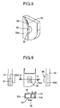
- FIG. 8 is a perspective view showing the second embodiment of the invention.
- FIG. 9 is a perspective view showing a third embodiment of the invention.
- FIG. 10 shows various views and a cross section showing an arrangement of another configuration of the third embodiment of the invention.
- FIG. 11 is a cross section showing an arrangement of another configuration of the third embodiment of the invention.
- FIG. 12 shows various views and a cross section showing a fourth embodiment of the invention
- FIG. 13 is a cross section showing an arrangement of another configuration of the fourth embodiment of the present invention.
- FIG. 14 is a plan view showing an arrangement of still another configuration of the fourth embodiment of the invention.
- FIG. 15 is a cross section showing a fifth embodiment of the invention.
- FIG. 16 is a cross section showing an arrangement of another configuration of the fifth embodiment of the invention.
- FIG. 17 is a cross section showing a sixth embodiment of the invention.
- FIG. 18 is a partial plan view showing the flow rate measuring device of the invention as installed in an air cleaner
- FIG. 19 is a schematic diagram showing a seventh embodiment of the invention.
- FIG. 20 is a cross section showing the seventh embodiment of the invention.
- FIG. 21 is a schematic diagram showing an arrangement of another configuration of the seventh embodiment of the invention.
- FIG. 22 is a cross section showing an arrangement of still another configuration of the seventh embodiment of the invention.
- FIG. 23 is a characteristic diagram of a flow rate measuring device according to an eighth embodiment of the invention.
- FIG. 24 is a control system diagram of an internal combustion engine using the flow rate measuring device of the invention.
- FIG. 25 is an exploded perspective view showing an arrangement of a sub-passage having an inertial effect produced by a vortex passage
- FIG. 26 is a diagram showing a principle of detecting a flow rate and a direction of an air flow by a flow rate measuring element of the invention.
- FIG. 27 is a cross section of a carrier inclined.
- a flow rate measuring element 1 is manufactured using a semiconductor fabrication technology. This is detailed below.
- a single crystal silicon substrate 2 is formed on its surface with a silicon dioxide layer as an electric insulation layer 3 by thermal oxidation or CVD (Chemical Vapor Deposition).
- a polycrystalline silicon layer is formed as by CVD and doped with phosphorus (P) as impurity by thermal diffusion or ion implantation to produce a desired resistance.
- the polysilicon layer is patterned to form a heating resistor 4 , an intake air temperature sensing resistor 5 , and temperature measuring resistors 6 , 7 .
- the resistors may be formed from platinum or the like, though it may raise cost slightly, to obtain a high temperature coefficient.
- a silicon nitride layer and a silicon dioxide layer are formed as a protective layer 8 as by CVD.
- the protective layer 8 is patterned to remove a portion of the protective layer where electrodes 13 are to be formed.
- an aluminum layer is formed and patterned by etching.
- a silicon nitride layer as a mask is formed by CVD on that surface of the single crystal silicon substrate 2 where the heating resistor 4 is not formed. The silicon nitride layer is then patterned and then subjected to an anisotropic etching to form the hollow portion 9 .
- the area where the heating resistor 4 and the temperature measuring resistors 6 , 7 are arranged is constructed as a thermally insulated thin film arrangement 10 . This arrangement can realize a fast response. Finally, the wafer is diced into chips.
- the diced flow rate measuring element 1 measures, for example, about 5 mm long by 2.5 mm wide.
- the carrier 11 of this invention is formed from a glass ceramic laminated substrate.
- the carrier 11 may also use a high-temperature sintered ceramic and a metal plate. Since the flow rate measuring element 1 should preferably be thermally insulated from surrounding members, it is effective to adopt a glass ceramic laminated substrate with a small thermal conductivity.
- the use of a laminated substrate makes it possible to integrate into the carrier 11 a control circuit 12 that supplies power to the flow rate measuring element 1 and processes signals from the flow rate measuring element 1 . This arrangement can reduce the number of parts and is advantageous in terms of cost and reliability. Further, inner layer conductors in the laminated substrate can be used to form a circuit for controlling the flow rate measuring element 1 and thereby reduce the size of the overall circuit, which in turn is conducive to a size reduction of the flow rate measuring device 100 .
- the flow rate measuring element 1 is bonded to the carrier 11 with epoxy- or silicone-based adhesive, and the electrodes of the flow rate measuring element 1 are electrically connected to the electrodes 13 of the carrier 11 through connecting lines 116 such as gold lines.
- the carrier 11 fitted with the flow rate measuring element 1 as shown in FIG. 3 , is mounted in a housing case 15 with a silicone-based adhesive. Further, the housing case 15 is inserted in an intake passage 16 .
- air (forward flow 20 ) flowing in a main passage 17 from the air cleaner toward the engine enters an inlet 31 of the sub-passage 18 a and flows toward its outlet 32 .
- the heating resistor 4 is controlled at a temperature predetermined degrees higher than that of the intake air temperature sensing resistor 5 .
- the heat of the heating resistor 4 heats the upstream temperature measuring resistor 6 and the downstream temperature measuring resistor 7 to predetermined temperatures.
- the upstream temperature measuring resistor 6 and the downstream temperature measuring resistor 7 receive theoretically equal quantities of heat from the heating resistor 4 so that their temperature difference is zero.
- the upstream temperature measuring resistor 6 is cooled more than the downstream temperature measuring resistor 7 , with the result that a temperature difference is produced between the upstream temperature measuring resistor 6 and the downstream temperature measuring resistor 7 .
- This causes a difference in resistance between them, generating a corresponding potential difference.
- the potential difference caused by the temperature difference corresponds to the amount of air flow and therefore the flow rate can be measured.
- the flow rate measuring element 1 detects a flow rate by using a phenomenon of thermal transfer to and from air (or other gases such as hydrogen gas), the flow rate cannot be measured unless the air contacts the surface of the flow rate measuring element 1 .
- the flow rate measuring element 1 of this invention has a thin-film arrangement 10 about 1–2 ⁇ m thick. When dust contained in the air taken in impinges against the element or water adheres to it, the thin film arrangement 10 may be destroyed.
- a sub-passage 18 as shown in FIG. 25 may be used which can separate dust and water from air by an inertial effect. While the air flow that has entered the inlet 31 of the sub-passage travels through the vortex passage until it reaches the flow rate measuring element 1 , contaminants contained in the air, such as dust and water, are urged against the outer circumferential surface of the passage by the inertial effect and discharged as is from the outlet 32 . The contaminants therefore cannot reach the surface of the flow rate measuring element 1 .
- the marks left on the surface of the flow rate measuring element 1 indicate that it was struck only by dust 5 ⁇ m across or smaller.
- the thin film arrangement 10 of the flow rate measuring element 1 can be reinforced so that it can withstand particles approximately 15 ⁇ m across impinging it at a velocity of 50 m/s.
- this sub-passage 18 can prevent a possible destruction of the element due to dust impingement.
- water an experiment was conducted in which about 20 L/min of water was continuously thrown into the main passage 17 . It was found in this experiment that the output of the flow rate measuring device did not fluctuate, indicating that no water reached the surface of the flow rate measuring element 1 .
- the sub-passage 18 has very high reliability as described above, its shape is asymmetric with respect to the backward flow 21 and the air outlet is provided on the side surface making it difficult for the backward flow 21 to enter the sub-passage. The measuring accuracy during pulsation therefore is not satisfactory.
- FIG. 1 shows a first embodiment of the present invention. This represents an arrangement that allows the backward flow 21 to be introduced relatively easily compared with the above-described sub-passage 18 of FIG. 25 .
- FIG. 4 shows details of the sub-passage 18 a of FIG. 1 .
- the sub-passage 18 a shown in FIG. 1 and FIG. 4 has a arrangement in which a sub-passage cover 30 a is formed with a stepped portion 33 to ensure that, when the flow rate measuring device is seen from the downstream side, the outlet portion receives a dynamic pressure, thus allowing the backward flow 21 to be introduced easily.
- FIG. 6 shows flow rate waveforms for the arrangements with and without the stepped portion 33 when there are air flow fluctuations. Regardless of the presence or absence of the stepped portion 33 , the flow rate waveforms for the forward flow 20 show little difference. But for the backward flow 21 , it is seen that the arrangement with the stepped portion 33 introduces a greater amount of air. Comparison between the average flow rates with and without the stepped portion 33 indicates that when the stepped portion 33 is not used, the average flow rate is high and its positive error with respect to the average flow rate of the main passage 17 is as high as around 40%. When the stepped portion 33 is provided, the average flow rate, though it has a positive error with respect to the average flow rate of the main passage 17 , is reduced to as low as about 10%.
- the stepped portion 33 is provided to both of these outlets, the measuring error is not reduced very much. This is because the provision of the stepped portion 33 at both of the outlets, while it increases the introduced amount of backward flow 21 , accelerates the discharge of the forward flow 20 . Hence, it is particularly effective to form the stepped portion 33 at only one of the two outlets.
- the measuring error can further be reduced, though not shown, by forming the stepped portion 33 at one of the two outlets and forming the other in such a shape that the forward flow 20 is not easily discharged.
- the measuring error may be reduced by correcting the backward flow characteristic curve as disclosed in JP-A-8-511627.
- This indeed is an effective means in an operation range where there is some backward flow 21 .
- the pulsating state there is an operation state in which the backward flow 21 begins to be produced as shown at point B of FIG. 6 .
- the measuring error cannot be reduced by the means for correcting the characteristic curve of the backward flow 21 .
- the means for introducing the backward flow 21 is also effective in such passages other than the inertial ones.
- the stepped portion 33 shown in FIG. 1 and FIG. 4 in which the stepped portion 33 is formed by using the entire surface of the outlet 32 , it may be replaced with a projecting portion 34 as shown in FIG. 5 to produce the similar effect.
- FIG. 7 shows a second embodiment and FIG. 8 shows its perspective view.
- the sub-passage 18 c has a slit 35 for introducing the backward flow 21 into it and also has a stepped portion 33 formed upstream of the slit to receive a dynamic pressure.
- the hole for introducing the backward flow 21 may be a circular one. In addition to the effect provided by the first embodiment, this arrangement facilitates the introduction of the backward flow through the slit 35 and thus can further reduce the measurement error when the backward flow 21 occurs.
- FIG. 9 shows a third embodiment of the invention.
- FIG. 9 illustrates an arrangement in which a plate member 36 is provided to a sub-passage cover 30 d to further facilitate the introduction of the backward flow.
- the provision of the plate member 36 can produce an effect of reducing the measurement errors.
- FIG. 11 Another example shape of the third embodiment is shown in FIG. 11 .
- FIG. 12 shows a plan view of a fourth embodiment of the present invention.
- FIG. 12 illustrates an arrangement in which another passage 37 is formed extending from the outlet 32 of a sub-passage cover 30 g . Forming the outlet in this configuration can facilitate the introduction of the backward flow 21 in the air flow pulsation state. This arrangement has an effect of reducing output noise compared with the first to third embodiment. This arrangement, however, has a drawback.
- the fourth embodiment is very effective for engines that produce a large backward flow 21 in a revolution range of around 600–1200 rpm
- the arrangements shown in the first to third embodiment are more advantageous for engines that produce a large backward flow 21 in a revolution range of 2000 rpm or higher.
- FIG. 13 shows an arrangement in which two sub-passage outlets 32 used in the arrangement of FIG. 12 are changed into only one sub-passage outlet. This arrangement further reduces output noise from that of the arrangement of FIG. 12 and, when compared with the first embodiment, the noise reduction can reach about 60% at maximum.
- FIG. 14 shows a sub-passage 18 k which has the inlet 31 set back compared with that of the sub-passage of FIG. 13 so that a distance from the sub-passage inlet 31 to the surface of the flow rate measuring element 1 is almost equal to a distance from the surface of the flow rate measuring element 1 to the outlet 32 .
- the arrangement shown in FIG. 13 has very small measurement errors exhibiting a good characteristic in an engine revolution range of 600–1200 rpm but, in a range of 2000 rpm or higher, tends to produce negative errors, as is the case with FIG. 12 .
- the arrangement of FIG. 14 eliminates waveform distortions at a revolution of 2000 rpm observed in the arrangement of FIG. 12 and therefore is advantageous for the engine with large pulsation amplitudes.
- FIG. 15 shows a fifth embodiment of the invention.
- a plate type flow rate measuring element 1 it is a known technique to reduce the output noise by slanting the element with respect to the air flow, as shown in FIG. 27 .
- the slanting of the element to improve the characteristic for the forward flow 20 degrades the sensitivity and output noise characteristic for the backward flow 21 , increasing the measurement errors when pulsation occur.
- the output noise is lowered. This in turn reduces the measurement errors in a state where output noise is easily generated, as in an air flow pulsating state.
- FIG. 16 shows another embodiment that has an effect of reducing the output noise as in the case of FIG. 15 .
- FIG. 17 shows a partial cross section of the sixth embodiment of the invention, which is equivalent to the E—E cross section of FIG. 5 .
- the air velocity at the surface of the flow rate measuring element 1 is faster on the inner side of the vortex than on the outer side when the air flow is steady.
- the velocity distribution in the sub-passage changes from that of the steady state condition and becomes uniform.
- the thin film arrangement 10 of the flow rate measuring element 1 is located near an inner circumference 41 of the sub-passage. Hence, the air velocity tends to slow down near the surface of the flow rate measuring element 1 during the pulsation state.
- the distance from a contracted portion 42 to the surface of the flow rate measuring element 1 is made to decrease toward the outer circumference 40 of the sub-passage.
- FIG. 18 shows the flow rate measuring element 100 installed in an air cleaner 102 .
- a technique is known in recent years which integrates the flow rate measuring device 100 in the air cleaner 102 from the standpoint of cost reduction, as shown in FIG. 18 .
- the pulsation generated in the intake manifold depend largely on the length of the intake manifold, or the distance from the engine to the inlet of the intake manifold, i.e., the most upstream portion of the air cleaner 102 .
- the length of the intake manifold changes, for example, a phenomenon is observed in which the engine revolution speed at which the backward flow 21 occurs varies greatly.
- the pulsation state changes greatly according to the shape of the intake manifold and the air cleaner 102 .
- the pulsation states are naturally different from each other. Although these pulsation states that vary in many ways can be dealt with by only the flow rate measuring device 100 , it is required that the sub-passage arrangement in the flow rate measuring device be changed for each air cleaner and engine.
- FIG. 21 and FIG. 22 show the seventh embodiment of the invention as installed in the sub-passage 18 e of FIG. 10 .
- FIG. 23 shows a characteristic curve for the eighth embodiment of the invention, which represents a relation between a flow rate and an output of the flow rate measuring device.
- the backward flow characteristic curve 24 is inversely symmetric to the forward flow characteristic curve 22 , as described earlier.
- the backward flow characteristic curve 24 deviates largely from a backward flow characteristic curve 23 .
- the flow rate-output characteristic in the forward-backward asymmetric sub-passage be used as a backward flow characteristic curve. Because the flows in the main passage 17 and the sub-passage during the pulsation state are totally different from those of the steady state, the use of the air flow rate and the flow rate measuring device output during the steady state as the backward flow characteristic curve is not very effective.
- the eighth embodiment of this invention determines the backward flow characteristic curve 23 from the flow rate in the main passage 17 and the output of the flow rate measuring device 100 during the pulsating condition.
- the flow rate in the main passage 17 is measured simultaneously by (1) a flow meter with a response speed of about 100 kHz well capable of following the pulsation and by (2) the flow rate measuring device 100 having the flow rate measuring element 1 installed in the sub-passage.
- the flow rate of the flow meter installed in the main passage 17 is allocated to the output obtained by the flow rate measuring device 100 to set the backward flow characteristic curve 23 .
- the backward flow characteristic curve 23 is set for each engine. This method is very advantageous as it eliminates the need for changing the shape of the flow rate measuring device 100 for each engine or for employing the means shown in the seventh embodiment.
- the above technique has a somewhat poor response to the pulsation in the main passage 17 for the forward flow 20 and, for the backward flow 21 , the same response as in the main passage 17 .
- the average flow rate tends to be slightly negative. It is therefore an effective means to correct the backward flow characteristic curve 23 by an amount corresponding to the degree to which the pulsation of the forward flow 20 cannot be followed.
- FIG. 24 shows a system diagram of an internal combustion engine such as a gasoline engine.
- Air to be taken into the engine flows through an air intake passage 16 , which includes an air cleaner 102 , an air intake passage 16 , a throttle angle sensor 103 , an idle speed control valve 104 , a throttle body 105 , and an intake manifold 106 .
- the air drawn in flows through the intake passage 16 , its flow rate and direction are detected by the flow rate measuring device 100 of this invention.
- the signals thus detected are sent as a voltage or frequency to a vehicle control unit 107 .
- the flow rate signal is used for the control of a combustion arrangement and subsystem consisting of an injector 108 , a tachometer 109 , an engine cylinder 110 , an intake manifold 111 and an oxygen density meter 112 .
- a diesel engine system though not shown, has basically the same configuration as the gasoline system and thus can use the flow rate measuring device of this invention.
- This embodiment therefore can provide a flow rate measuring device which is protected against destruction even when there is dust and water in the intake manifold, and which has high reliability for a long period of use and an excellent pulsation characteristic. Further, even in engines with large pulsation amplitudes, a flow rate measuring device with small measurement errors can be provided. Moreover, in engines that generates a backward flow 21 in all revolution ranges, a flow rate measuring device with small measurement errors can be provided.
- this embodiment can provide a flow rate measuring device with smaller output noise also in a steady state than that of a conventional passage having an inertial effects.
- a flow rate measuring device can be provided which has high reliability even when there is dust or oil in the intake manifold and also an excellent pulsation characteristic.
Abstract
Description
Claims (11)
Applications Claiming Priority (2)
| Application Number | Priority Date | Filing Date | Title |
|---|---|---|---|
| JP2001-274402 | 2001-09-11 | ||
| JP2001274402A JP3764860B2 (en) | 2001-09-11 | 2001-09-11 | Flow measuring device |
Publications (2)
| Publication Number | Publication Date |
|---|---|
| US20030046996A1 US20030046996A1 (en) | 2003-03-13 |
| US7032446B2 true US7032446B2 (en) | 2006-04-25 |
Family
ID=19099433
Family Applications (1)
| Application Number | Title | Priority Date | Filing Date |
|---|---|---|---|
| US10/083,403 Expired - Lifetime US7032446B2 (en) | 2001-09-11 | 2002-02-27 | Flowrate measuring device with improved flow introduction into sub-passage outlet |
Country Status (4)
| Country | Link |
|---|---|
| US (1) | US7032446B2 (en) |
| EP (1) | EP1291622B1 (en) |
| JP (1) | JP3764860B2 (en) |
| DE (1) | DE60237186D1 (en) |
Cited By (7)
| Publication number | Priority date | Publication date | Assignee | Title |
|---|---|---|---|---|
| US20070256493A1 (en) * | 2006-05-08 | 2007-11-08 | Hitachi, Ltd. | Flow Measurement Apparatus |
| US20090078041A1 (en) * | 2007-09-20 | 2009-03-26 | Yamatake Corporation | Flow sensor unit |
| KR20140010082A (en) * | 2011-03-18 | 2014-01-23 | 로베르트 보쉬 게엠베하 | Apparatus for recording at least one property of a fluid medium |
| US20150168191A1 (en) * | 2012-06-15 | 2015-06-18 | Hitachi Automotive Systems, Ltd. | Thermal Flow Meter |
| US9435669B2 (en) | 2012-12-20 | 2016-09-06 | Robert Bosch Gmbh | Intake gas sensor with vortex for internal combustion engine |
| US20170097252A1 (en) * | 2015-10-05 | 2017-04-06 | Wisenstech Ltd. | Composite mems flow sensor on silicon-on-insulator device and method of making the same |
| US20180299308A1 (en) * | 2015-10-05 | 2018-10-18 | Wisenstech Ltd. | Composite mems flow sensor on silicon-on-insulator device and method of making the same |
Families Citing this family (15)
| Publication number | Priority date | Publication date | Assignee | Title |
|---|---|---|---|---|
| DE10343793A1 (en) * | 2003-09-22 | 2005-04-14 | Robert Bosch Gmbh | Hot film air mass sensor with contacting by means of anisotropic conductive adhesive |
| JP4034251B2 (en) * | 2003-09-26 | 2008-01-16 | 株式会社ケーヒン | Intake device for internal combustion engine and method for measuring intake air amount |
| WO2005050143A1 (en) | 2003-11-20 | 2005-06-02 | Hitachi, Ltd. | Thermal flowmeter of fluid |
| JP4089654B2 (en) * | 2004-04-28 | 2008-05-28 | 株式会社デンソー | Air flow measurement device |
| JP3985801B2 (en) * | 2004-04-28 | 2007-10-03 | 株式会社デンソー | Air flow measurement device |
| DE102004035893B4 (en) * | 2004-07-23 | 2013-03-14 | Robert Bosch Gmbh | Device for determining at least one parameter of a medium flowing in a conduit |
| DE102007023840B4 (en) | 2007-05-21 | 2012-02-09 | Abb Ag | Thermal mass flow meter and method of operation |
| DE102008042807B4 (en) | 2008-10-14 | 2021-11-04 | Robert Bosch Gmbh | Device for determining a parameter of a flowing fluid medium |
| DE102009002853B4 (en) | 2009-05-06 | 2022-02-10 | Robert Bosch Gmbh | Device for detecting a parameter of a flowing fluid medium |
| JP5263216B2 (en) * | 2010-04-09 | 2013-08-14 | 株式会社デンソー | Air flow measurement device |
| JP5263324B2 (en) * | 2011-03-24 | 2013-08-14 | 株式会社デンソー | Air flow measurement device |
| JP5397425B2 (en) | 2011-07-16 | 2014-01-22 | 株式会社デンソー | Air flow measurement device |
| DE102014202105A1 (en) * | 2014-02-05 | 2015-08-06 | Continental Automotive Gmbh | Sensor device for determining a temperature |
| WO2016047243A1 (en) | 2014-09-26 | 2016-03-31 | 日立オートモティブシステムズ株式会社 | Thermal flowmeter |
| JP6365388B2 (en) * | 2015-04-21 | 2018-08-01 | 株式会社デンソー | Flow measuring device |
Citations (13)
| Publication number | Priority date | Publication date | Assignee | Title |
|---|---|---|---|---|
| US5537870A (en) * | 1994-10-03 | 1996-07-23 | Ford Motor Company | Contaminant free backflow reducing insert for mass air flow sensors |
| JPH08511627A (en) | 1994-03-28 | 1996-12-03 | ローベルト ボツシユ ゲゼルシヤフト ミツト ベシユレンクテル ハフツング | Air flow meter output signal correction method |
| US5631415A (en) * | 1992-09-17 | 1997-05-20 | Hitachi, Ltd. | Air flow rate measuring device |
| US5672822A (en) * | 1994-06-23 | 1997-09-30 | Nippondenso Co., Ltd. | Thermal flow meter with less turbulence in fluid flow |
| US5696321A (en) * | 1994-10-18 | 1997-12-09 | Hitachi, Ltd. | Thermal-type air flow measuring instrument with fluid-direction judging capability |
| US5804718A (en) * | 1996-04-24 | 1998-09-08 | Denso Corporation | Airflow meter having an inverted u-shape bypass passage |
| US5847275A (en) * | 1995-06-20 | 1998-12-08 | Nippondenso Co., Ltd. | Temperature detecting apparatus and thermal type flow meter using the same |
| US5892146A (en) * | 1996-09-02 | 1999-04-06 | Hitachi, Ltd. | Heating resistor type air flow meter with a measuring module inside the main air flow passage body |
| JPH11248505A (en) | 1998-01-09 | 1999-09-17 | Robert Bosch Gmbh | Apparatus for measuring flow rate of medium flowing through duct |
| US6079264A (en) * | 1997-04-17 | 2000-06-27 | Mitsubishi Denki Kabushiki Kaisha | Thermal flow sensor supporting element having a gradually increased portion between its distal ends |
| US6332356B1 (en) * | 1998-04-08 | 2001-12-25 | Robert Bosch Gmbh | Measuring device for measuring the mass of a medium flowing in a line |
| US6345531B1 (en) * | 1998-04-08 | 2002-02-12 | Robert Bosch Gmbh | Measuring device for measuring the mass of a flowing medium |
| US6571621B2 (en) * | 2001-02-28 | 2003-06-03 | Hitachi, Ltd. | Thermal flow rate measuring device |
Family Cites Families (6)
| Publication number | Priority date | Publication date | Assignee | Title |
|---|---|---|---|---|
| US5789673A (en) * | 1993-09-14 | 1998-08-04 | Hitachi, Ltd. | Thermal type air flow measuring instrument for internal combustion engine |
| US5355726A (en) * | 1994-01-03 | 1994-10-18 | Ford Motor Company | Housing for reducing back air flow to mass air flow sensors |
| JP3681627B2 (en) * | 1999-10-06 | 2005-08-10 | 日本特殊陶業株式会社 | Flow rate and flow rate measuring device |
| KR20010039993A (en) * | 1999-10-06 | 2001-05-15 | 오카무라 가네오 | Flow Rate and Flow Velocity Measurement Device |
| JP3709373B2 (en) * | 2001-12-19 | 2005-10-26 | 株式会社日立製作所 | Flow measuring device |
| JP4106224B2 (en) * | 2002-03-14 | 2008-06-25 | 株式会社デンソー | Flow measuring device |
-
2001
- 2001-09-11 JP JP2001274402A patent/JP3764860B2/en not_active Expired - Fee Related
-
2002
- 2002-02-27 DE DE60237186T patent/DE60237186D1/en not_active Expired - Lifetime
- 2002-02-27 EP EP02004281A patent/EP1291622B1/en not_active Expired - Lifetime
- 2002-02-27 US US10/083,403 patent/US7032446B2/en not_active Expired - Lifetime
Patent Citations (15)
| Publication number | Priority date | Publication date | Assignee | Title |
|---|---|---|---|---|
| US5631415A (en) * | 1992-09-17 | 1997-05-20 | Hitachi, Ltd. | Air flow rate measuring device |
| JPH08511627A (en) | 1994-03-28 | 1996-12-03 | ローベルト ボツシユ ゲゼルシヤフト ミツト ベシユレンクテル ハフツング | Air flow meter output signal correction method |
| US5672822A (en) * | 1994-06-23 | 1997-09-30 | Nippondenso Co., Ltd. | Thermal flow meter with less turbulence in fluid flow |
| US5894088A (en) * | 1994-06-23 | 1999-04-13 | Nippondenso Co., Ltd. | Thermal flow meter with less turbulence in fluid flow |
| US5537870A (en) * | 1994-10-03 | 1996-07-23 | Ford Motor Company | Contaminant free backflow reducing insert for mass air flow sensors |
| US5696321A (en) * | 1994-10-18 | 1997-12-09 | Hitachi, Ltd. | Thermal-type air flow measuring instrument with fluid-direction judging capability |
| US5847275A (en) * | 1995-06-20 | 1998-12-08 | Nippondenso Co., Ltd. | Temperature detecting apparatus and thermal type flow meter using the same |
| US5804718A (en) * | 1996-04-24 | 1998-09-08 | Denso Corporation | Airflow meter having an inverted u-shape bypass passage |
| US5892146A (en) * | 1996-09-02 | 1999-04-06 | Hitachi, Ltd. | Heating resistor type air flow meter with a measuring module inside the main air flow passage body |
| US6079264A (en) * | 1997-04-17 | 2000-06-27 | Mitsubishi Denki Kabushiki Kaisha | Thermal flow sensor supporting element having a gradually increased portion between its distal ends |
| JPH11248505A (en) | 1998-01-09 | 1999-09-17 | Robert Bosch Gmbh | Apparatus for measuring flow rate of medium flowing through duct |
| US6336360B1 (en) * | 1998-01-09 | 2002-01-08 | Robert Bosch Gmbh | Device for measuring the mass of a medium flowing in a line |
| US6332356B1 (en) * | 1998-04-08 | 2001-12-25 | Robert Bosch Gmbh | Measuring device for measuring the mass of a medium flowing in a line |
| US6345531B1 (en) * | 1998-04-08 | 2002-02-12 | Robert Bosch Gmbh | Measuring device for measuring the mass of a flowing medium |
| US6571621B2 (en) * | 2001-02-28 | 2003-06-03 | Hitachi, Ltd. | Thermal flow rate measuring device |
Cited By (13)
| Publication number | Priority date | Publication date | Assignee | Title |
|---|---|---|---|---|
| US20070256493A1 (en) * | 2006-05-08 | 2007-11-08 | Hitachi, Ltd. | Flow Measurement Apparatus |
| US7523659B2 (en) * | 2006-05-08 | 2009-04-28 | Hitachi, Ltd. | Flow measurement apparatus |
| US20090078041A1 (en) * | 2007-09-20 | 2009-03-26 | Yamatake Corporation | Flow sensor unit |
| US7765865B2 (en) * | 2007-09-20 | 2010-08-03 | Yamatake Corporation | Flow sensor unit including an insulating member interposed between the sensor chip and the attachment plate |
| US9618373B2 (en) * | 2011-03-18 | 2017-04-11 | Robert Bosch Gmbh | Device for detecting at least one property of a fluid medium |
| US20140060176A1 (en) * | 2011-03-18 | 2014-03-06 | Torsten Mais | Device for detecting at least one property of a fluid medium |
| KR20140010082A (en) * | 2011-03-18 | 2014-01-23 | 로베르트 보쉬 게엠베하 | Apparatus for recording at least one property of a fluid medium |
| US20150168191A1 (en) * | 2012-06-15 | 2015-06-18 | Hitachi Automotive Systems, Ltd. | Thermal Flow Meter |
| US10168195B2 (en) * | 2012-06-15 | 2019-01-01 | Hitachi Automotive Systems, Ltd. | Thermal flow meter capable of measuring flow rates in forward flow and reverse flow directions |
| US9435669B2 (en) | 2012-12-20 | 2016-09-06 | Robert Bosch Gmbh | Intake gas sensor with vortex for internal combustion engine |
| US20170097252A1 (en) * | 2015-10-05 | 2017-04-06 | Wisenstech Ltd. | Composite mems flow sensor on silicon-on-insulator device and method of making the same |
| US20180299308A1 (en) * | 2015-10-05 | 2018-10-18 | Wisenstech Ltd. | Composite mems flow sensor on silicon-on-insulator device and method of making the same |
| US10480974B2 (en) * | 2015-10-05 | 2019-11-19 | Siargo Ltd. | Composite MEMS flow sensor on silicon-on-insulator device and method of making the same |
Also Published As
| Publication number | Publication date |
|---|---|
| JP3764860B2 (en) | 2006-04-12 |
| JP2003083788A (en) | 2003-03-19 |
| EP1291622A3 (en) | 2006-05-10 |
| DE60237186D1 (en) | 2010-09-16 |
| EP1291622A2 (en) | 2003-03-12 |
| EP1291622B1 (en) | 2010-08-04 |
| US20030046996A1 (en) | 2003-03-13 |
Similar Documents
| Publication | Publication Date | Title |
|---|---|---|
| US7032446B2 (en) | Flowrate measuring device with improved flow introduction into sub-passage outlet | |
| JP3709373B2 (en) | Flow measuring device | |
| EP1452838B1 (en) | Thermal flow rate sensor | |
| US6516785B1 (en) | Air flow sensor | |
| JP4474308B2 (en) | Flow sensor | |
| JP3919829B2 (en) | Measuring device for measuring the mass of a medium flowing in a conduit | |
| JP2006047272A (en) | Flow sensor | |
| JP2001004420A (en) | Measuring apparatus of flow rate and flow velocity | |
| US6474154B2 (en) | Flow measurement device for measuring flow rate and flow velocity | |
| EP1221593A1 (en) | Gas flow measurement device | |
| KR20050074250A (en) | Air flow rate measuring device | |
| US9719824B2 (en) | Thermal air flow sensor | |
| US7472591B2 (en) | Thermal gas flow and control device for internal-combustion engine using the same | |
| JP3709339B2 (en) | Flow measuring device | |
| JP2000310552A (en) | Air flowmeter | |
| JPH09329473A (en) | Gas flow measuring device | |
| JP4906422B2 (en) | Thermal gas flow sensor and internal combustion engine controller using the same | |
| JP2008026278A (en) | Thermal gas flow sensor and apparatus for controlling internal combustion engine using the same | |
| JP2008026279A (en) | Thermal gas flow sensor and apparatus for controlling internal combustion engine using the same | |
| JPS601524A (en) | Semiconductor type flow-rate detecting device | |
| JPS59618A (en) | Detector for suction air quantity |
Legal Events
| Date | Code | Title | Description |
|---|---|---|---|
| AS | Assignment |
Owner name: HITACHI, LTD., JAPAN Free format text: ASSIGNMENT OF ASSIGNORS INTEREST;ASSIGNORS:NAKADA, KEIICHI;WATANABE, IZUMI;HORIE, JUNICHI;AND OTHERS;REEL/FRAME:012664/0219 Effective date: 20020207 Owner name: HITACHI CAR ENGINEERING CO., LTD., JAPAN Free format text: ASSIGNMENT OF ASSIGNORS INTEREST;ASSIGNORS:NAKADA, KEIICHI;WATANABE, IZUMI;HORIE, JUNICHI;AND OTHERS;REEL/FRAME:012664/0219 Effective date: 20020207 |
|
| STCF | Information on status: patent grant |
Free format text: PATENTED CASE |
|
| FEPP | Fee payment procedure |
Free format text: PAYOR NUMBER ASSIGNED (ORIGINAL EVENT CODE: ASPN); ENTITY STATUS OF PATENT OWNER: LARGE ENTITY |
|
| FPAY | Fee payment |
Year of fee payment: 4 |
|
| FEPP | Fee payment procedure |
Free format text: PAYER NUMBER DE-ASSIGNED (ORIGINAL EVENT CODE: RMPN); ENTITY STATUS OF PATENT OWNER: LARGE ENTITY |
|
| FEPP | Fee payment procedure |
Free format text: PAYOR NUMBER ASSIGNED (ORIGINAL EVENT CODE: ASPN); ENTITY STATUS OF PATENT OWNER: LARGE ENTITY |
|
| FPAY | Fee payment |
Year of fee payment: 8 |
|
| MAFP | Maintenance fee payment |
Free format text: PAYMENT OF MAINTENANCE FEE, 12TH YEAR, LARGE ENTITY (ORIGINAL EVENT CODE: M1553) Year of fee payment: 12 |