US7021760B2 - Soft contact lens capable of engagement with an eye either right way out or inside out - Google Patents
Soft contact lens capable of engagement with an eye either right way out or inside out Download PDFInfo
- Publication number
- US7021760B2 US7021760B2 US10/470,903 US47090303A US7021760B2 US 7021760 B2 US7021760 B2 US 7021760B2 US 47090303 A US47090303 A US 47090303A US 7021760 B2 US7021760 B2 US 7021760B2
- Authority
- US
- United States
- Prior art keywords
- lens
- orientation
- soft contact
- right way
- contact lens
- Prior art date
- Legal status (The legal status is an assumption and is not a legal conclusion. Google has not performed a legal analysis and makes no representation as to the accuracy of the status listed.)
- Expired - Lifetime
Links
Images


Classifications
-
- G—PHYSICS
- G02—OPTICS
- G02C—SPECTACLES; SUNGLASSES OR GOGGLES INSOFAR AS THEY HAVE THE SAME FEATURES AS SPECTACLES; CONTACT LENSES
- G02C7/00—Optical parts
- G02C7/02—Lenses; Lens systems ; Methods of designing lenses
- G02C7/04—Contact lenses for the eyes
- G02C7/048—Means for stabilising the orientation of lenses in the eye
-
- G—PHYSICS
- G02—OPTICS
- G02C—SPECTACLES; SUNGLASSES OR GOGGLES INSOFAR AS THEY HAVE THE SAME FEATURES AS SPECTACLES; CONTACT LENSES
- G02C7/00—Optical parts
- G02C7/02—Lenses; Lens systems ; Methods of designing lenses
- G02C7/021—Lenses; Lens systems ; Methods of designing lenses with pattern for identification or with cosmetic or therapeutic effects
-
- G—PHYSICS
- G02—OPTICS
- G02C—SPECTACLES; SUNGLASSES OR GOGGLES INSOFAR AS THEY HAVE THE SAME FEATURES AS SPECTACLES; CONTACT LENSES
- G02C7/00—Optical parts
- G02C7/02—Lenses; Lens systems ; Methods of designing lenses
- G02C7/04—Contact lenses for the eyes
-
- G—PHYSICS
- G02—OPTICS
- G02C—SPECTACLES; SUNGLASSES OR GOGGLES INSOFAR AS THEY HAVE THE SAME FEATURES AS SPECTACLES; CONTACT LENSES
- G02C7/00—Optical parts
- G02C7/02—Lenses; Lens systems ; Methods of designing lenses
- G02C7/04—Contact lenses for the eyes
- G02C7/041—Contact lenses for the eyes bifocal; multifocal
- G02C7/044—Annular configuration, e.g. pupil tuned
-
- G—PHYSICS
- G02—OPTICS
- G02C—SPECTACLES; SUNGLASSES OR GOGGLES INSOFAR AS THEY HAVE THE SAME FEATURES AS SPECTACLES; CONTACT LENSES
- G02C7/00—Optical parts
- G02C7/02—Lenses; Lens systems ; Methods of designing lenses
- G02C7/04—Contact lenses for the eyes
- G02C7/047—Contact lens fitting; Contact lenses for orthokeratology; Contact lenses for specially shaped corneae
-
- G—PHYSICS
- G02—OPTICS
- G02C—SPECTACLES; SUNGLASSES OR GOGGLES INSOFAR AS THEY HAVE THE SAME FEATURES AS SPECTACLES; CONTACT LENSES
- G02C7/00—Optical parts
- G02C7/10—Filters, e.g. for facilitating adaptation of the eyes to the dark; Sunglasses
- G02C7/105—Filters, e.g. for facilitating adaptation of the eyes to the dark; Sunglasses having inhomogeneously distributed colouring
Definitions
- the present invention relates to contact lenses and more particularly relates to an improved contact lens which can be fitted to an eye in a first orientation and also in another orientation. More particularly the invention relates to a soft contact lens which may be fitted according to conventional orientation right way out or inside out such that a front or back surface may oppose a corneal profile to effect refractive correction and to provide alternative fitting regimes for a variety of optical effects.
- the invention further comprises a contact lens which includes relief areas located outside optic zones on the front and back surface of the lens to enable fitting of the lens in a conventional orientation or in an inside out orientation.
- the present invention relates to a soft contact lens of the spherical, toroidal or non rotationally symmetrical type, wherein the lens is capable of flexing between a right way out orientation and an inside out orientation wherein fit criteria are satisfied and optical performance is not compromised.
- a soft lens is generally designed with a base curve (or curves) which is/are configured to fit the lens to the corneal/scleral profile of the eye, a diameter which is generally larger then the corneal diameter and an anterior curve (or curves) which provides for the refracting function of the lens.
- a base curve or curves
- anterior curve or curves
- the contact lens surfaces are designed such that portions of the base curve or the anterior curve are used to contribute specifically to the refracting effect as well as providing a fitting role.
- the lens will be provided with a base curve which is used to fit the lens to the eye and a front curve which, in combination with the base curve, provides the eye with a refractive correction.
- the contemporary method of fitting a soft contact lens takes into account the following;
- the most influential of the two will be the air/lens interface as the refractive index of air is 1.00. This is the reason designers of thin soft contact lenses can usually ignore the refracting influence of the post lens tear layer in their overall design calculations.
- the “normals to the no-strain boundary” can best be visualised by imagining a number of short lines that exist within the confines of the contact lens's anterior and posterior surfaces which are (and will always remain) perpendicular to a longer line that runs from one edge of the contact lens to the other in a plane of least resistance that exists somewhere between the anterior and the posterior surfaces
- the plane of least resistance is one that will describe the optimum path along which the contact lens can deform or bend whilst maintaining it's maximum level of equanimity. It is the path through the lens (in a profile perspective) which will be the least affected by the inevitable deformation of the lens's anterior and posterior surfaces as the posterior surface wraps to the corneal-scleral shape. The deformation of the posterior surface will cause a subsequent deformation of the anterior surface and it is the changes in the relationship between these two surfaces that are being heretofore described.
- the geometry of the contact lens itself has a direct bearing on the location of the no-strain boundary and the relationship between the anterior and posterior surfaces will also be influenced by the design geometry of the lens.
- the arcuate length of the anterior surface may differ slightly from the posterior surface.
- the anterior length (combined length of peripheral and optical sections) is usually greater in length than the posterior (combined back optical zone and peripheral zone).
- the arcuate lengths of either anterior or posterior surfaces can be altered with respect to each other in order to optimise their relationship when fitted in either orientation.
- the edge design may also influence the shift of the no-strain boundary when the lens is inverted.
- the edge configuration and its relationship with the respective surfaces can influence the in vivo characteristics of the lens.
- flexural modulus of the contact lens material Another factor that may have an influence on the ultimate position of the no-strain boundary within the lens is the flexural modulus of the contact lens material.
- Two lenses of identical design geometry but made from differing materials may exhibit quite different fitting characteristics because of this factor.
- the consistency of that modulus across the lens itself may in turn be influenced by way of water content variations in particular areas (e.g. from the central cornea where the lens is most exposed to evaporation and tear disruption, to areas of the lens which are less exposed to environmental effects, such as those that are predominately under the eyelids).
- a gradient from drier to wet with an associated decrease in flexural modulus in those drier areas (due to loss of the in-monomer lubricant (water)) and an associated reduction in interstitial polymer spaces may influence the position of the no-strain boundary.
- a lens of infinite flexure and infinite thinness would contain a no-strain boundary that was equidistant between the anterior and posterior surfaces for the entire diameter of the lens Therefore any deviation from that infinite ideal will result in a no-strain boundary of varying position and influence.
- both surfaces of such a lens are spherical in form, the resultant refracted rays of light will have been subjected to a varying rate of refraction from the center point of the lens out to the outermost optical chord.
- the LSA will be either negative or positive in nature depending on the sign of the lens.
- the peripheral light rays arrive at a range of virtual focus points that are further away from the lens than are those created by the rays of light passing through the paraxial area of the same lens.
- a lens with an optical influence such as described above (when measured in air), will exhibit a negative power shift from its center out towards its edge.
- This phenomenon can be reduced or eliminated by altering the spherical nature of at least one of the surfaces of the lens to an aspheric or non-spherical surface form such that ultimately, the angles of refraction from the paraxial rays out to the peripheral rays, focus to a common point. This will improve the resolution of that lens and subsequently reduce the magnitude of its defocussing effect. This can also be described as reducing the size of the lens's blur circles.
- the in vivo LSA is reduced somewhat from that measured in vitro. Nevertheless, for those lenses that are of medium or higher power (e.g. greater than ⁇ 6.00 DS and greater than +4.00 DS) the optical benefits of LSA reduction can be generally realised. Variations to the above mentioned wearing and fitting influences (by way of variations in the wrapping effect of the lens on the eye) may create corresponding variations in the ultimate optical and physical wearing experience. The contemporary contact lens fitter knows and understands these influences and effects and can order his or her patient's contact lenses accordingly. Most contact lens manufacturers today offer various lens designs and materials in an attempt to address some or all of the above. All of the above information is based upon the contemporary application of what can be considered basic and traditional optical and physiological phenomena.
- Lens orientation is expressed in terms such as “inside out” (inverted) or the “right way out”. This terminology or those which are similar are used to express whether or not the contact lens in question is being presented to the eye in the proper (right way out) fitting orientation.
- Patients are taught, at the time of dispensing, to recognize when their lenses are inside out and are shown how to place them on their eyes in the correct configuration. This is generally achieved by demonstrating to the patient that the lens will appear to have a slightly different shape when turned inside out. They are shown how to reconfigure the lens prior to insertion to ensure a “correct” fit. Some companies even mark their lenses with “anti-inversion” marks by engraving or laser etching means in an effort to provide the patient with an easy way to determine the correct lens orientation.
- This disparity in curvature will ensure that the lens can move with the lid action (a desirable action that serves to allow fresh tears to wash across and refresh the now vacated area of the corneal epithelium). This disparity is also the primary reason the lens can return to its equilibrated position on the cornea after the blinking phase is completed. As the lens is decentered away from equilibrium, a negative force builds up under the lens as the base curve to corneal/scleral disparity increases. Once the overriding influence of the upper lid is removed (by its retraction) the lens will able to resettle back where the post lens tear forces are at their lowest.
- the base curve of the soft lens is too tight for the eye, the lens will not move at all. If it is decentered by external means such as digital manipulation it will not return to a point of equilibrium. In this instance the disparity between the base curve and the corneal/scleral curve is too great in one direction and satisfactory equilibrium cannot be achieved.
- the present invention provides an alternative to the known soft contact lens wherein a lens is, according to the invention, capable of use on an eye in more than one orientation
- anterior or posterior surface lens may be presented to the corneal profile such that a back surface may act as an anterior surface and an anterior surface may act as a back surface by reorientation of the lens.
- the invention described herein seeks to redirect the focus of contact lens fitting philosophy away from the conventional methodology but embracing traditional fitting criteria.
- a soft contact lens capable of fitting to an eye in either a “right way out” or “inside out” orientation while satisfying the traditional fitting criteria and without affecting the comfort, centration or optical performance of the lens.
- Certain embodiments or derivations of the lens can create specific and different or the same or similar optical corrections depending on which way out the lens is worn. This is very useful in optimising or tuning a bifocal or multifocal lens fitting modality or tuning a mono-vision fitting without having to replace a lens.
- the present invention comprises:
- the present invention comprises;
- the present invention comprises;
- the present invention comprises:
- the present invention comprises:
- the present invention comprises:
- the present invention comprises:
- the formations may be located in a regions outside an optic zone of the lens and on either side of the lens.
- said first and second convex orientations of said lens provide a predetermined refractive correction of the eye of a wearer.
- the anterior and posterior surfaces include an optic zone and a fitting zone including formations providing relief areas, wherein the optic zone of each said first and second surfaces is capable of providing refractive correction options for a wearer and said relief areas allow satisfaction of fit criteria for each refractive option chosen and irrespective of whether the lens is in an inside out or right side out orientation.
- refractive correction by the lens is shared between the anterior and posterior surfaces.
- the present invention comprises:
- the lens is spherical, toriodal or non rotationally symmetrical and the conversion from right way out to inside out is effected by flexing the lens.
- Lens flexure is accommodated by at least one formation/s in or on either said first and second surfaces, wherein each of the formation/s provide means to assist flexure when the lens flexes between the right way out and inside out orientations.
- the formation/s is/are disposed anywhere on the first and/or second surfaces of the lens and wherein the formation/s allow/s the lens to satisfy fit criteria when the lens is in either the right way out or inside out orientation and irrespective of whether a lens base curve is oriented towards a cornea or faces away from the cornea.
- the formation/s result in an adjustment to a surface contour of said first and/or second surfaces.
- the surface adjustment can take a number of alternative forms. In one example
- a lens may have a formation which originates at a lens center and propagates radially in any meridian towards the lens edge.
- the formation/s may comprise at least one circumferentially disposed band/s defied by a thinning or thickening in the lens at the regions of said bands or it may comprise at least one spiral region on one or both surfaces of said first and/or second surfaces of said lens.
- the lens includes a formation/s comprising at least one oblique region/s on one or both surfaces of said first and/or second surfaces of said lens; wherein said oblique regions lie at an angle to any meridian of said lens.
- the lens according to the invention may further include formations in or on one or both said first and second surfaces of said lens comprising any one or any combination of, recesses, surface dimples, grooves, indents, circumferential bands, lines, fenestrations, dots, waveforms, reliefs, troughs, regions of thinning or thickening, spirals and oblique lines.
- the formations will be chosen for a particular lens according to the required resistance to flexure or strain relief required to satisfy fit criteria and refractive requirements when the lens is flexed from the right way out orientation to the inside out orientation.
- the formation/s is/may be positioned in a peripheral area of the lens in a site which optimizes a resistance relieving role performed by the formation/s when the lens undergoes flexure.
- Lens wrapping forces may be adjusted to counter a natural tendency of a lens capable of use right way out or inside out to curl (evert) off an eye.
- Non curved surfaces are used to eliminate said eversion tendency.
- Subtle differences in fitting characteristics of the lens may be made by adjusting flexure resistance values of anterior or posterior surfaces of the lens.
- the formation/s are disposed in either an optic zone or fit zone or both. Optic and fit zones and optical performance, centration and fit of the lens are not affected by the formations.
- Non curved surfaces are used to eliminate said eversion tendency.
- Subtle differences in fitting characteristics of the lens may be made by adjusting flexure resistance values of anterior or posterior surfaces of the lens.
- the formation/s are disposed in either an optic zone or fit zone or both optic and fit zones and optical performance, centration and fit of the lens are not affected by the formations.
- refractive corrections may be effected by the anterior and/or posterior surfaces in the right way out configuration and by an anterior and/or posterior surfaces formed in the inside out orientation and refractive corrections by the lens may be shared or distributed across the anterior and posterior surfaces irrespective of whether the lens is in the right way out orientation or inside out orientation.
- different optical corrections for an individual wearer can be made depending on selection of right way out or inside out orientation.
- the lens may include by way of example, a predetermined optical correction on one of the first and second surfaces and the same or a similar optical correction on an opposite surface. It may in an alternative include bifocal corrections on one side and one optical correction an another side, similar or the same bifocal corrections on both surfaces of said lens, one optical correction on one surface and a different single optical correction on an opposite surface, the same or different multi focal corrections on both the first and second surfaces of said lens.
- the lens may include a single correction on one of the first and second surfaces and a multi focal correction on the other of the first and second surfaces.
- the lens includes at least one colour on one side of the lens and at least one colour on an opposite side of the lens.
- the present invention comprises:
- the present invention comprises:
- the designer may create varying optical effects as mentioned above.
- the designer can create subtle differences in the fitting characteristics of the lens by adjusting the resistance values of anterior versus posterior surfaces.
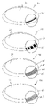
- FIG. 1 shows a perspective view of a lens according to one embodiment of the invention
- FIG. 2 shows a profile view of the lens of FIG. 1 ;
- FIG. 3 shows an alternative profile view of a lens of according to the invention.
- FIG. 4 shows a perspective view of an alternative lens according to an embodiment of the invention.
- FIG. 5 shows a profile view of a lens showing relief areas according to one embodiment of the invention
- FIG. 6 shows an alternative profile view of a lens showing formations/relief areas on one surface according to another embodiment of the invention.
- FIG. 7 shows a profile view of a lens showing formations/relief areas on opposite surfaces according to an alternative embodiment of the invention
- FIGS. 8 a - d show a variety of formations in or on a peripheral area of a lens according to embodiments of the invention.
- FIGS. 9 a–d show profiles views of lenses according to alternative embodiments.
- FIG. 10 shows a plan view and side elevation of a lens with non limiting examples of enlarged edge formations A–F and surface formations G–I. with posterior and anterior optic zones.
- FIG. 11 shows a plan view and side elevation of a lens with non limiting examples of enlarged edge formations A–F and surface formations G–I with an anterior
- the term right way out will be taken to refer to a lens fitted in a conventional orientation in which there is an anterior convex surface and a posterior convex surface opposing an eye and the term inside out will be taken to refer to that lens flexed inside out to cause the anterior surface in the right way out orientation to form a posterior convex surface and the posterior surface in the right way out orientation to form an anterior surface.
- the lens to be described below may be referred to as a ‘flipper’ or flexing lens due to its ability to be re oriented (flex) for reorientation on an eye.
- the flexing may be along an axis normal to the lens when viewed in profile by flipping of the lens thereby allowing the lens due to formations introduced into the lens forming relief areas to present to an eye in an inside out or right way out orientation.
- the lens according to the invention satisfies traditional fit and comfort criteria and fits optimally to the eye in either orientation by virtue of flexing of relief areas located in the optical and/or non-optical areas of the contact lens.
- the lens allows for flipping (flexing) or reorientation of the lens but with clinically acceptable fitting characteristics by way of formations such as bands that are located in the optical or non optical (peripheral area) of the lens.
- formations which provide areas of relief are generally thinner in profile than the surrounding areas and are shaped such that they allow the wrapping forces of the lens to be reoriented sympathetically with the general reorientation of the lens.
- formations in the regions of flexure in the peripheral area of the lens may contain at least one circumferential band (or bands) or area (s) that is/are thinner than the immediately surrounding areas of the lens when viewed in cross section.
- the formations providing the relief area(s) is/are positioned in the peripheral area of the lens nearer the lens edge in a selected site that optimizes a resistance relieving role the formations and thus relief areas provide. It (they) can also be placed in the outer areas of the optical zone in such a manner that it (or they) does/do not interfere with the optical performance of the lens.
- the formations in the lens accommodate the flexure by reducing resistance to flexure.
- These thinner or thicker area(s) can be designed controlled accurately by conventional means well known and understood in the art (especially with injection cast moulding means) and can be shaped or graduated in such a way as the designer sees fit in order to provide the wearer with suitable levels of in vivo comfort.
- the lens profile according to one embodiment is specifically thinner in that (or those) area (s) the lens will exhibit less resistance to any non-conformance of wrapping to the lens/scleral profile when presented to same. It will possess discreet and intentional areas of least resistance that will allow the lens to bend or wrap more easily in those areas than others.
- the designer is able to provide the lens with sections of least resistance that coincide with the most appropriate area within the lens that will allow it to conform to the lens scleral profile.
- the designer can create a lens that will conform to the corneal/scleral profile in a compliant and clinically acceptable manner in either orientation.
- the natural resistance to being “inside out” and the abstract and uncontrolled curvature changes that occur as a result will be reduced or eliminated by the relieving areas placed within the lens.
- the natural tendency for an “inside out” lens to curl off the eye when inserted will be eliminated by the reorientation of the wrapping forces.
- the lens may include the use of non-curved surfaces that can be shaped in such a way as to reduce inversion or flexure resistance as much as possible.
- non-curved surfaces or a combination of non-curved and curved surfaces the lens shape can be made to ‘flex’ inside out very easily.
- the flat sections can be used in conjunction with curved surfaces made from spherical sections.
- the formations introduced into the lens are thicker than adjacent to more conventionally designed areas of the lens. This may be required to create a stronger flexing or reorientation force.
- An alternative embodiment of the lens may employ an edge profile of the lens, immediately adjacent to a formation comprising a thinner area of least resistance.
- the lens When viewed in cross section, the lens would exhibit a bi-convex profile which is uniform and identical in profile on both surfaces. This peripheral rim would provide a controlling force on the edge of the lens that would prevent eversion (lifting) and would ensure that the edge demonstrated similar wrapping characteristics in either orientation.
- the uniform design could reflect the posterior and anterior edge shape as a mirror image of each other and thus provide for similar lid interaction profiles no matter which fitting orientation is chosen.
- the edge shapes may also be made from non-curved forms that may be of a flat or straight edged nature.
- a peripheral rim or edge of the lens is shaped with a slightly differing profile on one face from an opposite face. This could be used, either in conjunction with other design embodiments, or on its own to obtain varying fitting characteristics when fitted in opposing orientation whilst still wrapping appropriately to the sclera.
- Lens fit in either the right way out or inside out orientation will be aided by controlling of the optic zone dimensions and the sharing of the duties of the optic zone between the anterior and posterior surfaces of the lens.
- Traditional soft spherical lenses and some soft toric lenses simply use the posterior surface of the lens for fitting to the eye of the wearer.
- the radius is selected from a fitting standpoint versus a refractive platform and thus becomes a baseline for the final choice of refractive curve on the anterior surface when the final refractive solution is considered.
- the power that is required to satisfy the wearer's prescription is then derived from the anterior surface curvature alone.
- the disparity between the posterior (base curve) radius and the anterior optic radius creates the refractive quantum.
- the aforementioned outline describes a typical soft contact lens in today's market.
- Some known lenses in the market use a specifically designed discreet refracting segment located in the posterior surface of the lens. It is generally located in the center of the base radius and can be steeper or flatter in radius to the main base curve radius. If it is steeper in radius it will create a more minus effect to the overall refractive power of the lens and if it is flatter it will create a more plus effect to the overall refractive power of the lens.
- This type of refracting segment has proved to be a successful design feature in soft toric lenses and high minus lenses as described in Australian patent no 620083, U.S. Pat. No. 5,125,728 and European patent 0398984.
- the primary advantage of such a design feature is in the provision of a means to arbitrarily control and influence the thickness profile and refracting curves of the lens, independent of the curvatures of the eye.
- the fitting and refracting advantages are obvious.
- the designer can create the optimum set of curves to refract the eye with any given lens without being overly restricted by fitting and corneal alignment concerns.
- the use of a selectively designed posterior optical segment is useful as it can enhance or assist the wrapping effect of the lens, when it is placed on the eye in its “inside out” orientation, by virtue of reducing the natural resistance to flexing of the optic junction of the lens.
- a lens has a thicker junction thickness, it will resist reorientation more so than a lens with a thinner junction thickness, as the natural difference between the anterior and posterior curves will be lessened.
- this is particularly relevant as the posterior curve is generally steeper in radius than the anterior curve and will prove more difficult to re-orient away from its natural shape as it increases in thickness. This thickness increase occurs from the center of the lens out to the edge of the optic junction, whereupon it can generally be reduced by the judicious use of closely approximated peripheral curves.
- a minus lens is designed in a conventional manner it will encounter a natural resistance to wrapping or curving in its opposite (or unnatural) orientation as the optic junction will present the lens with an area of resistance.
- the reduction in junction thickness by the use of reduced optic zones can be further enhanced by the use of non-spherical curvatures and shapes that promote a smooth and seamless transition between itself and the surrounding area of the lens. This will improve the wrapping response of the lens when re-orientated even further.
- Such an optical design can also be used in conjunction with a surrounding relieving area (s) similar to the peripheral relieving band (s) so that the lens will wrap even more easily when re-orientated on the eye.
- the relieving area (s) can be positioned in close proximity to the optic junction or in close proximity to the blend (s) that make up the transition from segment to surrounding surface. It will be appreciated by persons skilled in the art of lens design, that many combinations and derivations of the above mentioned design principle are possible.
- the lens includes at least one formation providing a strain relief area within an optical area such that the relief area assists in the reorientation flexing of the lens by reducing natural resistance to flexing when it is positioned on the eye in either the right way out conventional orientation or inverted
- the optic junction is generally constant and can be designed so that it is quite thin.
- the optic thickness however will increase with the strengthening of the lens power and may create a natural resistance to optimal wrapping when re-orientated on the eye
- a design feature of the lens proposed herein is the reduction in center thickness of the positive powered lens by the use of a posterior optical segment which is less steep in radius than the surrounding curvature (s). This approach will allow the designer to reduce the optical center thickness from that of a conventional designed lens and thus overcome its natural resistance to being “inside out”. This too can be enhanced by the use of an adjacent or nearby formations providing relieving area (s).
- the key to the lens achieving fitting success in either orientation is the reduction, removal or reshaping of those naturally occurring areas of resistance that are created by conventional designs. Once this is achieved and the lens can be fitted either “inside out” or the “right way out”, the designer is free to create varying optical effects as mentioned above. Or the designer can create subtle differences in the fitting characteristics of the lens by adjusting the resistance values of anterior versus posterior surfaces.
- a contact lens created using the aforementioned design principles could provide the lens designer, the lens manufacturer, the Practitioner and the wearer with many potential advantages, both from a fitting and wearing point of view and from an optical flexibility point of view.
- a design such as this allows the patient to handle the lens far more easily, not worry about correct orientation prior to insertion and generally just concentrate on enjoying wearing a comfortable lens.
- a lens manufactured in accordance with the invention allows the wearer to select the optimum correction for his or her optical needs at any time by lens fitting orientation.
- a lens such as described before could offer the Practitioner a genuine advantage in prescribing flexibility from both a fitting and optical perspective.
- FIG. 1 shows a perspective view of a lens 1 according to one embodiment of the invention
- FIG. 2 shows a profile view of the lens of FIG. 1 .
- Lens 1 comprises first and second opposed surfaces 2 and 3 which are each capable of forming anterior or posterior surfaces depending upon the orientation to the eye. As shown in FIG. 2 surface 2 forms a convex anterior outer surface and surface 3 forms a convex posterior surface. Upon flexing of lens 1 surface 2 may assume a posterior surface and surface 3 may assume an anterior surface role. Lens 1 further comprises outer zone profiles or formations 4 which provide relief areas when the lens flexes between a right way out and inside out orientation.
- FIG. 3 shows an alternative profile view of a lens 5 with formations 6 in a peripheral region of the lens.
- FIG. 4 shows a perspective view of an alternative lens 7 including an optic zone 8 and peripheral or outer fitting zone 9 . These characteristics are known in soft contact lenses.
- a typical known lens may have an optic zone on either an anterior surface or posterior surface or both.
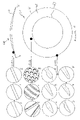
- FIG. 5 shows a profile view of a lens 10 showing relief areas according to one embodiment of the invention.
- Lens 10 comprises circumferential formations II providing a relief areas in an outer peripheral zone on an anterior surface 12 according to another embodiment of the invention.
- FIG. 6 shows a profile view of a lens 13 showing relief areas according to another embodiment of the invention.
- Lens 13 comprises circumferential formations 14 , 15 and 16 providing strain relief areas in an outer peripheral zone on an anterior surface 17 according to another embodiment of the invention.
- FIG. 7 shows a profile view of a lens 18 showing circumferential formation 19 forming relief areas according to another embodiment of the invention.
- Circumferential formation 19 provides a strain relief areas in an outer peripheral zone on an anterior surface 20 .
- Formation 19 is thinner than its surrounding region and accommodates flexure of the lens when flexing between a right way out orientation and an inside out orientation.
- FIGS. 2 , 3 , 5 , 6 and 7 may be continuously intermittently circumferential.
- FIG. 8A-D each show an alternative formations providing relief areas in a peripheral area of a lens.
- FIG. 8A shows a lens 30 including an optical region 31 and an outer peripheral region 32 .
- outer peripheral region 32 includes an enlarged band 33 which may continuously or intermittently extend circumferentially about lens 30 .
- FIG. 8A shows a lens 34 including an optical region 35 and an outer peripheral region 36 .
- outer peripheral region 36 includes an intermittent enlarged formation 37 which may intermittently extend circumferentially about lens 34 .
- FIG. 8C shows a lens 38 including an optical region 39 and an outer peripheral region 40 .
- outer peripheral region 40 includes an enlarged series of bands 41 , 42 and 43 which continuously extend circumferentially about lens 38 .
- FIG. 8D shows a lens 44 including an optical region 45 and an outer peripheral region 46 .
- outer peripheral region 46 includes an enlarged view of a plurality of small lines or bands 47 which continuously extend circumferentially about lens 44 .
- Each of the non limiting formations described are capable of accommodating lens flexure between the right way out orientation and the inside out orientation.
- FIGS. 9 a–d show profiles views of lenses according to alternative embodiments in which edge formations have been included in outer regions of the lenses.
- FIG. 10 shows a plan view and side elevation of a lens with non limiting examples of enlarged edge formations A–F and surface formations G–I. with posterior and anterior optic zones.
- Lens 50 of FIG. 10 is shown in plan and profile.
- the plan view shows lens 50 including outer peripheral edge 51 an outer zone 52 which may be termed a fit zone and an anterior optic zone 53 and posterior optic zone 54 .
- the two optic zones 53 and 54 share the optical duties to achieve the required refractive effect.
- FIGS. 10 A–F show examples of non limiting enlarged edge formations in profile which may be introduced into the lens to achieve the required relief areas. There is a wide variety of options open to the lens designer to achieve the required lens flexing.
- Formations 10 A, B, C and F are symmetrical whereas formations 10 D, and E are asymmetrical.
- FIG. 10 also shows examples of enlarged formations G, H and I which may be located on peripheral outer zone 52 . The same formations of G, H and I are shown in profile adjacent the profile view of lens 50 .
- FIG. 11 shows a plan view and side elevation of a lens with non limiting examples of enlarged edge formations A–F and surface formations G–I with an anterior.
- the lens of FIG. 11 is substantially the same as that of FIG. 10 except that a back optic zone is omitted.
- the plan view shows lens 60 including outer peripheral edge 61 an outer zone 62 which may be termed a fit zone and an anterior optic zone 63 .
- optic zone 63 assumes the optical duties to achieve the required refractive effect. Refractive correction by this lens is thus achieved on its anterior surface 63 .
- FIG. 11 also shows examples of enlarged formations G, H and I which may be located on peripheral outer zone 62 .
- the same formations of G, H and I are shown in profile adjacent the profile view of lens 60 . It can be seen that there are potentially a wide variety of formations and profiles which can achieve the objects of the invention described herein.
- the lens employs the use of concentrically positioned alternating optical zones or bands that incorporate optical changes and shifts such that the lens in situ can generate a bifocal or multifocal effect.
- the alternating bands could also be designed to create a single vision effect or to create aspheric or other such optical effects the designer should desire. Arranging the alternating bands of differing power or surface geometry on both the anterior and posterior surfaces to create conflicting or complimentary effects could also be useful to the designer.
- the lens uses at least one relieving area within the optical area such that the relieving area assists in the reorientation of the lens when it is positioned on the eye in either it's conventional orientation or inverted orientation. The use of thoughtful design principles could achieve this affect without sacrificing optical effectivity.
- the lens employs such surface geometry which is generated by non-rotationally symmetrical means and such geometry being able to be altered or tailored to the designers wishes by virtue of its orientation on the eye.
- colouration of lenses may be adapted to the lens according to the present invention.
- coloured or opaque tinted contact lenses There has been an increase in the popularity and usage of coloured or opaque tinted contact lenses around the world. These lenses most commonly have a coloured iris pattern printed or bonded on the anterior surface or affixed within the matrix of the lens and are capable of changing the natural eye colour to something new.
- a wearer with brown irides for example can change their eye colour to blue by wearing a pair of blue opaque tinted contact lenses.
- they are coloured in such a way that they are effective on one side of the lens only. This is because the base curve side is always fitted facing the eye and would not benefit from having any specific colour. As such there can be only one colour per lens.
- a wearer has the choice of two colours by the simple action of reorienting their lenses on their eyes.
- the anterior side of the lens may be tinted blue whilst the posterior side may be tinted green.
- the patient's eye colour could be either green or blue.
- a lens is provided with colouration on one or both sides of the lens.
- the lens may be prepared with, the same colour on both sides (this might be preferred where flexing provides an alternative refractive correction without a colour change upon flexing), two different colours, one on each side.
- the lens may also be prepared with more than one colour on one or both sides.
- the above colour regimes may be employed in the flexing lens irrespective of whether a wearer requires a refractive correction or not. In the case of a coloured lens with no refractive correction the flexing would would be for a cosmetic colour change.
- the lens can be inserted either . . . “inside out” or “the right way out” as the designer or wearer chooses. This makes the wearing of contact lenses far more practical for patients as they no longer have to determine which way the lens should be oriented before insertion. According to the invention the lens would fit in a similar manner whichever way it was placed on the eye. This is advantageous for disposable lenses as they can be handled less before being placed on the eye and they would not need to be orientated upon removal from the disposable packaging. This is a very convenient way to handle lenses every day. It would be appreciated by those skilled in the art of contact lens design that a lens designed and manufactured as described herein would not necessarily require any anti-inversion marking because the lens may be placed right way out or inside out.
- the lens may be designed to exhibit a controlled amount of in vivo fitting flexure, depending on its orientation when inserted. This would make the lens useful for optimising a fitting problem without having to resort to the ordering or selecting of a totally new base curve. Both practitioner and patient would find this an advantage depending on the wearer's requirements at the time. An anti-inversion mark would allow the patient to determine the correct orientation.
- the lens can optically capitalise on the refractive changes created when either the anterior or the posterior surfaces of the lens are presented to the corneal/scleral profile.
- the change in surface shape, created by differing wrap effects between the anterior or the posterior surface when either of them are presented to the corneal/scleral profile, may be used to “tune” a lens from the perspective of optimising a refractive result in vivo. Or it may be used to create a mild multifocal effect by way of inducing a planned aspheric or non-spherical shape in vivo and thus create a progressive power shift (this could be in either positive or negative direction in relation to the apical power).
- This type of lens would be very useful to a patient who wanted to wear single vision lenses at times and yet wanted to wear bifocal or multifocal lenses at others.
- the wearer could obtain a bifocal or multifocal effect at their discretion, simply by removing the lenses and reinserting them in their opposing orientation. Alternatively the wearer may find the reorientation of just one of the lenses to be optimal also.
- This design principle allows the wearer to enjoy a very flexible wearing regime, depending on the designs used.
- the lens may also be designed to enhance an otherwise standard monovision fitting regime by offering a choice of at least two power alternatives per lens, depending on the orientation of each of the lenses. This actually creates a possibility of wearing four different powers or four different optical variances from only two lenses. Obviously this presents as a significant advantage to the practitioner and patient alike.
- the above mentioned monovision fitting regime can be further enhanced by virtue of at least one of the lenses being able to create a multifocal effect when worn and being able to vary that multifocal effect when inverted in wearing orientation. This would offer even more flexibility and variability to the practitioner and patient and would allow for far more accurate fine tuning of any given monovision or multifocal fitting regime.
- Another advantageous version of this lens design principle is the enhancement of it's optical advantages or features by the judicious use of freznel or freznel style optical principles.
- a lens manufactured with a diffractive type of optical design principle incorporated, could very easily create alternate optical results when fitted to the eye in both the conventional and opposite orientation.
- the optical eschelets will experience a change in their principle diffracting angles along with the change in wrap effect in vivo when the lens is fitted to the eye in either its conventional or “inside out” orientation.
Abstract
Description
- 1. The scleral (white of the eye) curve is somewhat flatter than the corneal curve (s) and will therefore have an influence on the fitting of any soft contact lens that has a large enough diameter to encroach out from the cornea onto the sclera. Virtually all soft contact lenses today are fitted with the diameter encroaching out onto the sclera for reasons of comfort and in vivo stability.
- 2. A fitting allowance has to be made for this scleral flattening effect and this results in a soft contact lens being fitted to the eye with a base curve (s) which is/are flatter than the corneal curve (s). The degree of difference between the base curve (s) of the contact lens and the corneal curve (s) can vary with the design but will still result in an overall flatter curve (s) than the corneal curve (s). The base curve (s) of the soft contact lens will be generally steeper than the scleral curve (s) and this combination of fitting effects (in combination with the inherent flexibility of a soft lens) assists in keeping the contact lens in close apposition to the eye.
- 3. As the soft contact lens is made of a flexible polymer it will generally conform to the corneal/scleral profile and ‘wrap’ onto the eye.
- 4. The optimum fitting of a soft contact lens requires that the lens be not fitted too tightly to the eye, such that it will exhibit some free movement when physically influenced in some way (e.g. during the blinking phase of the eyelids), yet still return to a centrally placed position on the eye once that influence is removed. This important requirement is the one of the main reasons behind the fitting philosophy that provides for a soft contact lens with a flatter than corneal curve (s) base curve (s).
- 5. The lens must conform to the corneal/scleral profile and yet still exhibit a freedom of movement under an influence (such as the lid forces during blinking). It should not be fitted so tightly that its edges impinge on the scleral blood vessels and it should not unduly depress the bulbar conjunctiva. It should not be fitted so loosely however that it moves excessively on the eye whether under physical influence or not. A loose fitting lens will lag and descend on the eye in the primary gaze. It will generally exhibit a greater degree of discomfort than an optimally fitted lens.
- 6. A soft lens is designed with its overall thickness being a critical part of that design. This is due to the fact that the eye receives most of the oxygen it needs for good morphology from the atmosphere and as such suffers when there is a reduction in that uptake of oxygen. This can be caused by a medium such as a contact lens presenting as a barrier to oxygen flux. A soft contact lens can cause a condition known as oedema in the sensitive cornea by way of oxygen deprivation. The oxygen is drawn from the atmosphere through the contact lens by way of a gaseous flux and can be impeded if the material component (plastic) of the lens acts as a barrier to that gas transmission. Traditional soft lens materials are made up of polymers that do not allow the passage of oxygen via themselves but contain or bind water in various amounts and configurations and as such provide a passage for oxygen flux. In the case of traditional soft contact lens polymers therefore, it is preferable that the lens polymer content be kept to a practical minimum. It should be noted however that there might exist certain restrictions with regards to this minimum in relation to maintaining a practical level of refractive index and a practical handling modulus. Such a philosophy, amongst other design considerations, results in the lens being kept to a minimum thickness. This design concept improves the amount of oxygen available to the cornea for any given water content lens and can increase the in vivo flexibility of that lens.
- 7. The tear layer, which resides under the lens and in front of the cornea, is very thin and has very little influence on the overall refractive effect of the lens/eye combination. A number of factors contribute to this phenomenon, not the least of which is the fact that the refractive index of the tears is approximately 1.336 whereas the typical soft lens refractive index is approximately 1.41. As the corneal refractive index is approximately 1.375 there is little difference between the refractive index of the tear layer and that of the cornea. If the tear layer is sufficiently thin it can be considered negligible for the purposes of the overall calculation of the refraction of light. The overriding interfaces for the purposes of light refraction into the eye will be as follows . . . .
- 1: air/anterior surface of the contact lens,
- 2: posterior surface of the contact lens/the cornea.
- 8. Conventional contemporary soft contact lens fitting accepts that, as the contact lens conforms or wraps intimately to the cornea-scleral profile, it does not need to have the post lens tear layer taken into account as a refracting component and therefore generally precludes the need to do the same when designing the appropriate lens for any given eye.
- 9. It is also generally accepted however, that this wrapping or deforming from the lens's in vitro state can have a noticeable refractive influence on the eye as the curves of the contact lens ‘change’ in order to accommodate the profiles of the cornea and sclera. As the radius of curvature of the scleral profile is flatter than the generally accepted “best fit” contact lens base curve (s) and the corneal curve (s) is steeper than same, it is usually accepted that the central base section (posterior surface) of the contact lens has to steepen in curvature (s) so that it conforms to the corneal curve (s) and the posterior peripheral section has to flatten in order to conform to the scleral profile.
- 10. Another contact lens related phenomenon that should be considered is an optical effect known as longitudinal spherical aberration (LSA). This is generally acknowledged as a simple form of aberration that exists within a family of optical aberrations. It is usually accepted (for simple lens design theory) as being rotationally symmetrical in nature but can occur meridionally in the case of toroidal lenses as well. Other optical aberrations that may create issues for optical designers include chromatic aberration, coma, non-rotationally symmetrical derivations of LSA and irregular surface created aberrations. Longitudinal Spherical Aberration (LSA) is just one of the more common aberrations to be considered in simple contact lens design.
- a soft contact lens for fitting to any eye of a wearer, wherein, the lens is capable of providing adequate fit and stability for the wearer irrespective of whether the lens is presented to a corneal profile of an eye in a right way out or inside out orientation wherein the selection of right way out or inside out orientation may be made by flexing the lens. According to one embodiment, the lens is capable of a variety of refractive corrections irrespective of the orientation of the lens.
- a soft contact lens for refractive correction of an eye of a wearer, wherein the lens is capable of providing refractive correction, adequate fit and stability for a wearer irrespective of whether the lens is presented to a corneal profile of an eye right way out or inside out; wherein the lens is capable of providing a wearer with bifocal or multifocal correction by removing the lens and reinserting the lens in an opposing orientation.
- a soft contact lens for fitting to an eye of a wearer, wherein the lens may be presented to a corneal profile of an eye right way out or inside out; wherein the lens has first and second opposing surfaces wherein one or both said surfaces includes at least one colour. According to one embodiment, the lens is capable of a variety of refractive corrections of an eye in both orientations.
- a soft contact lens for refractive correction of an eye of a wearer, wherein the lens provides refractive correction, adequate fit and stability for a wearer irrespective of whether the lens is presented to a corneal profile of an eye right way out or inside out; the lens further comprising relief areas inside and/or outside an optic zone, on an anterior and/or posterior surface; the lens also satisfying fit criteria irrespective of use in the right way out or inside out orientation of the lens.
- a soft contact lens capable of assuming a generally convex shape when placed on an eye of a wearer, the lens including a first surface which may form an anterior surface or posterior surface and a second surface on an opposite side of the lens to the first surface and capable of forming a posterior surface or anterior surface; wherein, the first and second surfaces form either said anterior or posterior surfaces according to the orientation of the lens selected for placement on the eye of a wearer.
- a soft contact lens capable of assuming a generally convex shape when placed on an eye of a wearer, the lens including a first surface which may form an anterior surface or posterior surface and a second surface capable of forming a posterior surface or anterior surface wherein the first and second surfaces form either said anterior or posterior surfaces according to whether the lens is oriented right way out or inside out on an eye of the wearer; the lens further comprising formations inside and/or outside an optic zone on the anterior and/or posterior surfaces which enable the lens to satisfy fit criteria for the wearer when said lens flexes between said right way out and inside out and inside out and right way out orientation.
- a soft contact lens for refractive correction of an eye of a wearer, the lens capable of forming a first convex orientation in which the lens has a convex anterior surface and a concave posterior surface and a second convex orientation formed by displacement of the lens by inversion along an axis normal to said anterior and posterior surfaces of said first convex orientation when the lens is viewed in profile, wherein in said second convex orientation of said lens, the anterior surface of said first convex orientation forms a posterior surface of said second convex orientation and the posterior surface of said first convex orientation forms an anterior surface of said second convex orientation. Preferably the lens includes formations which provide relief areas inside and/or outside an optic zone on the anterior and posterior surfaces which enable the lens to satisfy fit criteria for the wearer irrespective of whether the lens is in the right way out or inside out orientation.
- a method for fitting a contact lens to an eye of a wearer for refractive correction; wherein the contact lens is capable of forming a first convex orientation in which the lens has a convex anterior surface and a concave posterior surface and a second convex orientation formed by displacement of the lens by inversion along an axis normal to said anterior and posterior surfaces of said first convex orientation when the lens is viewed in profile, wherein in said second convex orientation of said lens, the anterior surface of said first convex orientation forms a posterior surface of said second convex orientation and the posterior surface of said first convex orientation forms an anterior surface of said second convex orientation; and wherein the lens includes relief areas outside or at the outer extremities of an optic zone on the anterior and posterior surface which enable the lens to satisfy fit criteria for the wearer irrespective of whether the lens is in the right way out or inside out orientation;
- the method comprising the steps of;
- a) prior to fitting the lens, reduction, removal or reshaping of normally occurring areas of resistance to said lens;
- b) designing an optical effect in the lens according to requirements of a wearer;
- c) taking the soft contact lens and electing to fit said lens in either said inside out or right way out orientation.
- a soft contact lens for fitting to an eye of a wearer in either a right way out orientation or in an inside out orientation; the lens including first and second generally arcuate surfaces each terminating at an edge of the lens; wherein, each said first and second surfaces are capable of forming either an anterior convex or posterior concave surface; wherein in said right way out orientation there is provided an anterior convex surface and a posterior concave surface and in said inside out orientation said right way out anterior convex surface is converted to a posterior concave surface and said right way out posterior concave surface is converted to a convex anterior surface.
- a method of fitting a contact lens to an eye of a wearer; the lens including first and second generally arcuate surfaces terminating in a lens edge; wherein each said first and second surfaces are capable of forming either an anterior convex or posterior concave surface; wherein in said right way out orientation there is provided an anterior convex surface and a posterior concave surface and in said inside out orientation said right way out anterior convex surface is converted to a posterior concave surface and said right way out posterior concave surface is converted to a convex anterior surface; the method comprising the step of;
- a) fitting said lens to said eye in said right way out orientation;
- b) removing said lens and electing to refit the lens in the inside out orientation.
- a method of fitting a contact lens to an eye of a wearer; the lens including first and second generally arcuate surfaces terminating in a lens edge; wherein each said first and second surfaces are capable of forming either an anterior convex or posterior concave surface; wherein in said right way out orientation there is provided an anterior convex surface and a posterior concave surface and in said inside out orientation said right way out anterior convex surface is converted to a posterior concave surface and said right way out posterior concave surface is converted to a convex anterior surface; the method comprising the step of;
- a) fitting said lens to said eye in said inside out orientation;
- b) removing said lens and refitting said lens in said right way out orientation.
Claims (44)
Applications Claiming Priority (3)
| Application Number | Priority Date | Filing Date | Title |
|---|---|---|---|
| AUPR2766A AUPR276601A0 (en) | 2001-01-31 | 2001-01-31 | A contact lens for refractive correction and capable of engagement with an eye either inside out or right way out |
| AUPR2766 | 2001-01-31 | ||
| PCT/AU2002/000098 WO2002061497A1 (en) | 2001-01-31 | 2002-01-31 | A soft contact lens capable of engagement with an eye either right way out or inside out |
Publications (2)
| Publication Number | Publication Date |
|---|---|
| US20040061828A1 US20040061828A1 (en) | 2004-04-01 |
| US7021760B2 true US7021760B2 (en) | 2006-04-04 |
Family
ID=3826793
Family Applications (1)
| Application Number | Title | Priority Date | Filing Date |
|---|---|---|---|
| US10/470,903 Expired - Lifetime US7021760B2 (en) | 2001-01-31 | 2002-01-31 | Soft contact lens capable of engagement with an eye either right way out or inside out |
Country Status (12)
| Country | Link |
|---|---|
| US (1) | US7021760B2 (en) |
| EP (1) | EP1364248B1 (en) |
| JP (2) | JP4310105B2 (en) |
| KR (2) | KR20040043110A (en) |
| CN (1) | CN1308733C (en) |
| AU (2) | AUPR276601A0 (en) |
| CA (1) | CA2435745C (en) |
| ES (1) | ES2547238T3 (en) |
| NO (1) | NO20033403L (en) |
| NZ (1) | NZ527223A (en) |
| WO (1) | WO2002061497A1 (en) |
| ZA (1) | ZA200305731B (en) |
Cited By (19)
| Publication number | Priority date | Publication date | Assignee | Title |
|---|---|---|---|---|
| US20060100703A1 (en) * | 2004-11-10 | 2006-05-11 | Scott Evans | Method of implanting an intraocular lens |
| US20070168027A1 (en) * | 2006-01-13 | 2007-07-19 | Brady Daniel G | Accommodating diffractive intraocular lens |
| US20070242216A1 (en) * | 2006-04-12 | 2007-10-18 | Rikke Dootjes | Lens |
| US20070252947A1 (en) * | 2006-04-28 | 2007-11-01 | Wei-Pin Hsu | Contact lenses |
| US20100328940A1 (en) * | 2009-06-30 | 2010-12-30 | Fu Zhun Precision Industry (Shen Zhen) Co., Ltd. | Lens, led module and illumination apparatus utilizing the same |
| US7862169B2 (en) | 2006-09-29 | 2011-01-04 | Johnson & Johnson Vision Care, Inc. | Contact lenses and methods for their design |
| US20110019400A1 (en) * | 2009-07-21 | 2011-01-27 | Fu Zhun Precision Industry (Shen Zhen) Co., Ltd. | Lens, led module and illumination apparatus utilizing the same |
| US20120059464A1 (en) * | 2010-09-03 | 2012-03-08 | Abbott Medical Optics Inc. | Microincision lens |
| US20120099077A1 (en) * | 2010-10-26 | 2012-04-26 | Abt Niels A | Ophthalmoscopic contact lens |
| US9011532B2 (en) | 2009-06-26 | 2015-04-21 | Abbott Medical Optics Inc. | Accommodating intraocular lenses |
| US9039760B2 (en) | 2006-12-29 | 2015-05-26 | Abbott Medical Optics Inc. | Pre-stressed haptic for accommodating intraocular lens |
| US9198752B2 (en) | 2003-12-15 | 2015-12-01 | Abbott Medical Optics Inc. | Intraocular lens implant having posterior bendable optic |
| US9271830B2 (en) | 2002-12-05 | 2016-03-01 | Abbott Medical Optics Inc. | Accommodating intraocular lens and method of manufacture thereof |
| US9504560B2 (en) | 2002-01-14 | 2016-11-29 | Abbott Medical Optics Inc. | Accommodating intraocular lens with outer support structure |
| US9603703B2 (en) | 2009-08-03 | 2017-03-28 | Abbott Medical Optics Inc. | Intraocular lens and methods for providing accommodative vision |
| US9814570B2 (en) | 1999-04-30 | 2017-11-14 | Abbott Medical Optics Inc. | Ophthalmic lens combinations |
| US9968441B2 (en) | 2008-03-28 | 2018-05-15 | Johnson & Johnson Surgical Vision, Inc. | Intraocular lens having a haptic that includes a cap |
| US20220113558A1 (en) * | 2020-10-13 | 2022-04-14 | Johnson & Johnson Vision Care, Inc. | Contact lens position and rotation control using the pressure of the eyelid margin |
| US11707354B2 (en) | 2017-09-11 | 2023-07-25 | Amo Groningen B.V. | Methods and apparatuses to increase intraocular lenses positional stability |
Families Citing this family (27)
| Publication number | Priority date | Publication date | Assignee | Title |
|---|---|---|---|---|
| US20040085510A1 (en) * | 2002-10-30 | 2004-05-06 | O'brien Keith T. | Contact lenses for correction of irregular corneal surfaces |
| US7138638B2 (en) * | 2003-11-20 | 2006-11-21 | Juni Jack E | Edge effects treatment for crystals |
| JP4674893B2 (en) * | 2004-12-28 | 2011-04-20 | 株式会社サンコンタクトレンズ | contact lens |
| US7878650B2 (en) * | 2006-06-29 | 2011-02-01 | Fritsch Michael H | Contact lens materials, designs, substances, and methods |
| US20080013044A1 (en) * | 2006-07-11 | 2008-01-17 | Procornea Nederland B.V. | Contact lens |
| TWI487516B (en) * | 2007-08-22 | 2015-06-11 | Novartis Ag | Presbyopic treatment system |
| EP2259741B1 (en) * | 2008-04-01 | 2017-11-08 | Scientific Optics, Inc. | Universal contact lens posterior surface construction |
| KR100931595B1 (en) * | 2009-03-12 | 2009-12-14 | 주식회사 지앤에이치 | Mounting device for light emitting diode lamp |
| EP2503380B1 (en) * | 2009-11-17 | 2014-04-23 | Menicon Co., Ltd. | Contact lens |
| JP4768075B1 (en) * | 2010-08-25 | 2011-09-07 | 博紀 藤田 | Vision correction contact lens kit |
| US8672476B2 (en) * | 2011-03-24 | 2014-03-18 | Johnson & Johnson Vision Care, Inc. | Contact lenses with improved movement |
| US8690320B2 (en) * | 2011-06-01 | 2014-04-08 | Bausch & Lomb Incorporated | Contact lenses having hybrid orientation features |
| CN102262307A (en) * | 2011-08-17 | 2011-11-30 | 陈迪生 | New soft cornea contact lens |
| JP5536265B2 (en) * | 2013-07-30 | 2014-07-02 | 株式会社メニコン | contact lens |
| SG10201801793YA (en) * | 2013-09-11 | 2018-04-27 | Novartis Ag | Contact lens inspection system and method |
| WO2015060211A1 (en) * | 2013-10-21 | 2015-04-30 | 株式会社メニコン | Contact lens |
| US9389434B2 (en) | 2013-11-22 | 2016-07-12 | Johnson & Johnson Vision Care, Inc. | Contact lenses with improved oxygen transmission |
| US20150248019A1 (en) * | 2014-02-28 | 2015-09-03 | Johnson & Johnson Vision Care, Inc. | Contact lenses with apparent motion and other optical effects |
| US9412029B2 (en) * | 2014-12-12 | 2016-08-09 | Iris Id, Inc. | Apparatus for recognizing iris and operating method thereof |
| WO2017013644A2 (en) * | 2015-07-22 | 2017-01-26 | Pres-By Vision Ltd | Contact lens for vision correction |
| EP3933872B1 (en) * | 2019-02-28 | 2023-11-01 | OMRON Corporation | Photoelectric sensor and method for manufacturing same |
| US11221499B2 (en) * | 2019-03-29 | 2022-01-11 | Johnson & Johnson Vision Care, Inc. | Invertible lens and method of design |
| CN113093405B (en) * | 2020-01-08 | 2023-05-26 | 星欧光学股份有限公司 | Contact lens and contact lens product |
| US11934043B2 (en) | 2020-04-30 | 2024-03-19 | Coopervision International Limited | Myopia control lens and related methods |
| US11762220B2 (en) | 2020-04-30 | 2023-09-19 | Coopervision International Limited | Multifocal ophthalmic lenses and related methods |
| US11520166B2 (en) | 2020-09-24 | 2022-12-06 | Johnson & Johnson Vision Care, Inc. | Cosmetic contact lens with reversible effects |
| CN112666723B (en) * | 2020-12-31 | 2021-11-16 | 菲特兰有限公司 | Scleral mirror with fenestration and pocket |
Citations (17)
| Publication number | Priority date | Publication date | Assignee | Title |
|---|---|---|---|---|
| FR2248527A1 (en) | 1973-10-19 | 1975-05-16 | Lagouche Pierre | Extensible corneal lenses of rigid plastic material - incorporating narrow hinge zones of flexible material |
| US4896958A (en) * | 1988-02-18 | 1990-01-30 | Ames Keith S | Flexible contact lens for enhanced movement on the eye |
| EP0453231B1 (en) | 1990-04-17 | 1996-03-20 | JOHNSON & JOHNSON VISION PRODUCTS, INC. | Process for hydrating soft contact lenses |
| US5936704A (en) * | 1997-12-22 | 1999-08-10 | Gabrielian; Grant | Marked contact lens bearing optical marking element |
| US6199982B1 (en) | 1998-08-26 | 2001-03-13 | Menicon Co., Ltd. | Presbyopia correction contact lens |
| US6206520B1 (en) | 1999-03-25 | 2001-03-27 | Johnson & Johnson Vision Care, Inc. | Contact lenses with contoured edges |
| US6244709B1 (en) | 1999-03-12 | 2001-06-12 | Bausch & Lomb Incorporated | Multifocal lens article |
| US6260966B1 (en) | 1998-03-11 | 2001-07-17 | Menicon Co. Ltd. | Multifocal ocular lens |
| US6322215B1 (en) | 2000-08-07 | 2001-11-27 | Alexander C. Bristol | Non-progressive trifocal ophthalmic lens |
| US6357876B1 (en) | 1998-10-16 | 2002-03-19 | Menicon Co., Ltd. | Multifocal ocular lens having intermediate-distance vision correction region formed in central part of vision correction area |
| US6364483B1 (en) | 2000-02-22 | 2002-04-02 | Holo Or Ltd. | Simultaneous multifocal contact lens and method of utilizing same for treating visual disorders |
| US6390622B1 (en) | 1999-07-19 | 2002-05-21 | Hecht Contactlinsen Gmbh | Contact lens or intraocular lens having near and distance zones |
| US6457826B1 (en) | 1998-08-06 | 2002-10-01 | John B. W. Lett | Multifocal aspheric lens |
| US6467903B1 (en) | 2000-03-31 | 2002-10-22 | Ocular Sciences, Inc. | Contact lens having a uniform horizontal thickness profile |
| US6474814B1 (en) | 2000-09-08 | 2002-11-05 | Florida Optical Engineering, Inc | Multifocal ophthalmic lens with induced aperture |
| US20030016331A1 (en) | 2001-07-17 | 2003-01-23 | Mandell Robert B. | Bifocal contact lens with secondary prism |
| US6511178B1 (en) | 1999-07-19 | 2003-01-28 | Johnson & Johnson Vision Care, Inc. | Multifocal ophthalmic lenses and processes for their production |
Family Cites Families (37)
| Publication number | Priority date | Publication date | Assignee | Title |
|---|---|---|---|---|
| US3468602A (en) * | 1966-07-11 | 1969-09-23 | Hyman Rosen | Contact lens with flexible central portion |
| US3950082A (en) * | 1973-01-10 | 1976-04-13 | David Volk | Ophthalmic lens for presbyopia and aphakia |
| US4190621A (en) * | 1977-03-10 | 1980-02-26 | Martin Greshes | Method for molding optical plastic lenses of the standard and bifocal type |
| US4113088A (en) * | 1977-06-06 | 1978-09-12 | Binkhorst Richard D | Sterile package |
| DE2749144C2 (en) * | 1977-11-03 | 1979-12-06 | Bruno 6000 Frankfurt Koller | Contact lens |
| FR2416104A1 (en) * | 1978-02-07 | 1979-08-31 | Essilor Int | MOLDING DEVICE, IN PARTICULAR FOR SOFT CONTACT LENS |
| US4173281A (en) * | 1978-06-12 | 1979-11-06 | Intermedics Intraocular, Inc. | Intraocular lens packaging system |
| US4392569A (en) * | 1979-06-06 | 1983-07-12 | Shoup Leo E | Soft contact lens asepticizing case |
| US4257521A (en) * | 1979-11-16 | 1981-03-24 | Stanley Poler | Packaging means for an intraocular lens |
| US4284399A (en) * | 1980-06-23 | 1981-08-18 | American Optical Corporation | Contact lens mold |
| DE3037252C2 (en) * | 1980-10-02 | 1983-12-29 | Wilhelm Rogg Kunststoff-Metallisierung, 8500 Nürnberg | Injection mold for the production of moldings from two types of plastic |
| US4423809A (en) * | 1982-02-05 | 1984-01-03 | Staar Surgical Company, Inc. | Packaging system for intraocular lens structures |
| US4616910A (en) * | 1983-03-01 | 1986-10-14 | Klein Robert E | Visual indicator on soft contact lenses |
| US4618227A (en) * | 1983-10-07 | 1986-10-21 | Vistakon, Inc. | Soft contact lens |
| CA1265688A (en) * | 1984-10-17 | 1990-02-13 | Alain Rainville | Bi-focal corneal lens and method of making the same |
| US4691820A (en) * | 1985-11-18 | 1987-09-08 | Vistakon, Inc. | Package for hydrophilic contact lens |
| US4890912A (en) * | 1986-01-24 | 1990-01-02 | Rients Visser | Trifocal eye-contact lens |
| US5176686A (en) * | 1987-03-26 | 1993-01-05 | Poley Brooks J | Apparatus for packaging, folding, rigidifying and inserting an intraocular lens |
| US4850689A (en) * | 1988-03-07 | 1989-07-25 | Bruce A. Martin | Near vision contact lens and methods of making and using it |
| US5062701A (en) * | 1988-06-07 | 1991-11-05 | Wesley-Jessen Corporation | Asymmetric contact lens |
| US4923296A (en) * | 1988-07-14 | 1990-05-08 | Erickson Paul M | Oriented simultaneous vision bifocal contact lenses or the like utilizing introaocular suppression of blur |
| US4944580A (en) * | 1988-07-27 | 1990-07-31 | Thermo Electron Technologies Corp. | Active segmented mirror including a plurality of piezoelectric drivers |
| US4830481A (en) * | 1988-08-12 | 1989-05-16 | Minnesota Mining And Manufacturing Company | Multifocal diffractive lens |
| US5076683A (en) * | 1988-09-14 | 1991-12-31 | Allergan, Inc. | Spuncast compound contact lens |
| CA2009668A1 (en) * | 1989-02-16 | 1990-08-16 | Ashok R. Thakrar | Colored contact lenses and method of making same |
| US5054610A (en) * | 1989-05-31 | 1991-10-08 | Ciba-Geigy Corporation | Disposable single-use contact lens conditioning package |
| US5349395A (en) * | 1991-08-23 | 1994-09-20 | Nick Stoyan | Multiple focus corneal contact lens and method for treating myopia |
| US5191365B1 (en) * | 1991-08-23 | 2000-08-15 | Contex Inc | Corneal contact lens and method for treating myopia |
| US5271875A (en) * | 1991-09-12 | 1993-12-21 | Bausch & Lomb Incorporated | Method for molding lenses |
| JP2934133B2 (en) * | 1992-10-27 | 1999-08-16 | 株式会社メニコン | Soft contact lens |
| US5448312A (en) * | 1992-12-09 | 1995-09-05 | Johnson & Johnson Vision Products, Inc. | Pupil-tuned multifocal ophthalmic lens |
| US5436678A (en) * | 1993-09-30 | 1995-07-25 | Wilmington Partners L.P. | Aspheric multifocal contact lens |
| US5517260A (en) * | 1994-03-28 | 1996-05-14 | Vari-Site, Inc. | Ophthalmic lens having a progressive multifocal zone and method of manufacturing same |
| US5635998A (en) * | 1994-12-06 | 1997-06-03 | Baugh; Thomas K. | Translating multifocal contact lens |
| IL118065A0 (en) * | 1995-05-04 | 1996-08-04 | Johnson & Johnson Vision Prod | Aspheric toric lens designs |
| US5684560A (en) * | 1995-05-04 | 1997-11-04 | Johnson & Johnson Vision Products, Inc. | Concentric ring single vision lens designs |
| US6030077A (en) * | 1998-03-11 | 2000-02-29 | Menicon Co., Ltd. | Multifocal ocular lens having intermediate region with continuously varying optical power |
-
2001
- 2001-01-31 AU AUPR2766A patent/AUPR276601A0/en not_active Abandoned
-
2002
- 2002-01-31 KR KR10-2003-7010044A patent/KR20040043110A/en active Search and Examination
- 2002-01-31 AU AU2002229400A patent/AU2002229400B2/en not_active Ceased
- 2002-01-31 EP EP02710680.6A patent/EP1364248B1/en not_active Expired - Lifetime
- 2002-01-31 US US10/470,903 patent/US7021760B2/en not_active Expired - Lifetime
- 2002-01-31 WO PCT/AU2002/000098 patent/WO2002061497A1/en active IP Right Grant
- 2002-01-31 KR KR1020087027214A patent/KR100971319B1/en active IP Right Grant
- 2002-01-31 ES ES02710680.6T patent/ES2547238T3/en not_active Expired - Lifetime
- 2002-01-31 CN CNB028074718A patent/CN1308733C/en not_active Expired - Lifetime
- 2002-01-31 CA CA 2435745 patent/CA2435745C/en not_active Expired - Fee Related
- 2002-01-31 JP JP2002562007A patent/JP4310105B2/en not_active Expired - Fee Related
- 2002-01-31 NZ NZ527223A patent/NZ527223A/en unknown
-
2003
- 2003-07-24 ZA ZA200305731A patent/ZA200305731B/en unknown
- 2003-07-30 NO NO20033403A patent/NO20033403L/en not_active Application Discontinuation
-
2009
- 2009-02-06 JP JP2009025795A patent/JP4870789B2/en not_active Expired - Fee Related
Patent Citations (17)
| Publication number | Priority date | Publication date | Assignee | Title |
|---|---|---|---|---|
| FR2248527A1 (en) | 1973-10-19 | 1975-05-16 | Lagouche Pierre | Extensible corneal lenses of rigid plastic material - incorporating narrow hinge zones of flexible material |
| US4896958A (en) * | 1988-02-18 | 1990-01-30 | Ames Keith S | Flexible contact lens for enhanced movement on the eye |
| EP0453231B1 (en) | 1990-04-17 | 1996-03-20 | JOHNSON & JOHNSON VISION PRODUCTS, INC. | Process for hydrating soft contact lenses |
| US5936704A (en) * | 1997-12-22 | 1999-08-10 | Gabrielian; Grant | Marked contact lens bearing optical marking element |
| US6260966B1 (en) | 1998-03-11 | 2001-07-17 | Menicon Co. Ltd. | Multifocal ocular lens |
| US6457826B1 (en) | 1998-08-06 | 2002-10-01 | John B. W. Lett | Multifocal aspheric lens |
| US6199982B1 (en) | 1998-08-26 | 2001-03-13 | Menicon Co., Ltd. | Presbyopia correction contact lens |
| US6357876B1 (en) | 1998-10-16 | 2002-03-19 | Menicon Co., Ltd. | Multifocal ocular lens having intermediate-distance vision correction region formed in central part of vision correction area |
| US6244709B1 (en) | 1999-03-12 | 2001-06-12 | Bausch & Lomb Incorporated | Multifocal lens article |
| US6206520B1 (en) | 1999-03-25 | 2001-03-27 | Johnson & Johnson Vision Care, Inc. | Contact lenses with contoured edges |
| US6390622B1 (en) | 1999-07-19 | 2002-05-21 | Hecht Contactlinsen Gmbh | Contact lens or intraocular lens having near and distance zones |
| US6511178B1 (en) | 1999-07-19 | 2003-01-28 | Johnson & Johnson Vision Care, Inc. | Multifocal ophthalmic lenses and processes for their production |
| US6364483B1 (en) | 2000-02-22 | 2002-04-02 | Holo Or Ltd. | Simultaneous multifocal contact lens and method of utilizing same for treating visual disorders |
| US6467903B1 (en) | 2000-03-31 | 2002-10-22 | Ocular Sciences, Inc. | Contact lens having a uniform horizontal thickness profile |
| US6322215B1 (en) | 2000-08-07 | 2001-11-27 | Alexander C. Bristol | Non-progressive trifocal ophthalmic lens |
| US6474814B1 (en) | 2000-09-08 | 2002-11-05 | Florida Optical Engineering, Inc | Multifocal ophthalmic lens with induced aperture |
| US20030016331A1 (en) | 2001-07-17 | 2003-01-23 | Mandell Robert B. | Bifocal contact lens with secondary prism |
Cited By (28)
| Publication number | Priority date | Publication date | Assignee | Title |
|---|---|---|---|---|
| US9814570B2 (en) | 1999-04-30 | 2017-11-14 | Abbott Medical Optics Inc. | Ophthalmic lens combinations |
| US9504560B2 (en) | 2002-01-14 | 2016-11-29 | Abbott Medical Optics Inc. | Accommodating intraocular lens with outer support structure |
| US10206773B2 (en) | 2002-12-05 | 2019-02-19 | Johnson & Johnson Surgical Vision, Inc. | Accommodating intraocular lens and method of manufacture thereof |
| US9271830B2 (en) | 2002-12-05 | 2016-03-01 | Abbott Medical Optics Inc. | Accommodating intraocular lens and method of manufacture thereof |
| US9198752B2 (en) | 2003-12-15 | 2015-12-01 | Abbott Medical Optics Inc. | Intraocular lens implant having posterior bendable optic |
| US20060100703A1 (en) * | 2004-11-10 | 2006-05-11 | Scott Evans | Method of implanting an intraocular lens |
| US8377123B2 (en) | 2004-11-10 | 2013-02-19 | Visiogen, Inc. | Method of implanting an intraocular lens |
| US20070168027A1 (en) * | 2006-01-13 | 2007-07-19 | Brady Daniel G | Accommodating diffractive intraocular lens |
| US20070242216A1 (en) * | 2006-04-12 | 2007-10-18 | Rikke Dootjes | Lens |
| US7699465B2 (en) | 2006-04-12 | 2010-04-20 | Rikke Dootjes | Contact lens |
| US20070252947A1 (en) * | 2006-04-28 | 2007-11-01 | Wei-Pin Hsu | Contact lenses |
| US7441892B2 (en) * | 2006-04-28 | 2008-10-28 | Wei-Pin Hsu | Contact lenses |
| US7862169B2 (en) | 2006-09-29 | 2011-01-04 | Johnson & Johnson Vision Care, Inc. | Contact lenses and methods for their design |
| US9039760B2 (en) | 2006-12-29 | 2015-05-26 | Abbott Medical Optics Inc. | Pre-stressed haptic for accommodating intraocular lens |
| US9968441B2 (en) | 2008-03-28 | 2018-05-15 | Johnson & Johnson Surgical Vision, Inc. | Intraocular lens having a haptic that includes a cap |
| US9011532B2 (en) | 2009-06-26 | 2015-04-21 | Abbott Medical Optics Inc. | Accommodating intraocular lenses |
| US10052194B2 (en) | 2009-06-26 | 2018-08-21 | Johnson & Johnson Surgical Vision, Inc. | Accommodating intraocular lenses |
| US20100328940A1 (en) * | 2009-06-30 | 2010-12-30 | Fu Zhun Precision Industry (Shen Zhen) Co., Ltd. | Lens, led module and illumination apparatus utilizing the same |
| US20110019400A1 (en) * | 2009-07-21 | 2011-01-27 | Fu Zhun Precision Industry (Shen Zhen) Co., Ltd. | Lens, led module and illumination apparatus utilizing the same |
| US9603703B2 (en) | 2009-08-03 | 2017-03-28 | Abbott Medical Optics Inc. | Intraocular lens and methods for providing accommodative vision |
| US20120059464A1 (en) * | 2010-09-03 | 2012-03-08 | Abbott Medical Optics Inc. | Microincision lens |
| US8992611B2 (en) * | 2010-09-03 | 2015-03-31 | Abbott Medical Optics Inc. | Microincision lens |
| US9474595B2 (en) | 2010-09-03 | 2016-10-25 | Abbott Medical Optics Inc. | Microincision lens and method for inserting same |
| US10226326B2 (en) | 2010-09-03 | 2019-03-12 | Johnson & Johnson Surgical Vision, Inc. | Microincision lens |
| US20120099077A1 (en) * | 2010-10-26 | 2012-04-26 | Abt Niels A | Ophthalmoscopic contact lens |
| US8678593B2 (en) * | 2010-10-26 | 2014-03-25 | Alcon Research, Ltd. | Ophthalmoscopic contact lens |
| US11707354B2 (en) | 2017-09-11 | 2023-07-25 | Amo Groningen B.V. | Methods and apparatuses to increase intraocular lenses positional stability |
| US20220113558A1 (en) * | 2020-10-13 | 2022-04-14 | Johnson & Johnson Vision Care, Inc. | Contact lens position and rotation control using the pressure of the eyelid margin |
Also Published As
| Publication number | Publication date |
|---|---|
| AUPR276601A0 (en) | 2001-02-22 |
| EP1364248A4 (en) | 2005-02-09 |
| KR100971319B1 (en) | 2010-07-20 |
| NO20033403D0 (en) | 2003-07-30 |
| EP1364248A1 (en) | 2003-11-26 |
| NO20033403L (en) | 2003-09-29 |
| CA2435745C (en) | 2008-08-05 |
| AU2002229400B2 (en) | 2007-03-01 |
| JP4310105B2 (en) | 2009-08-05 |
| KR20040043110A (en) | 2004-05-22 |
| NZ527223A (en) | 2005-09-30 |
| JP4870789B2 (en) | 2012-02-08 |
| ZA200305731B (en) | 2004-08-27 |
| JP2004522183A (en) | 2004-07-22 |
| CN1308733C (en) | 2007-04-04 |
| ES2547238T3 (en) | 2015-10-02 |
| KR20080100294A (en) | 2008-11-14 |
| WO2002061497A1 (en) | 2002-08-08 |
| CA2435745A1 (en) | 2002-08-08 |
| JP2009139974A (en) | 2009-06-25 |
| US20040061828A1 (en) | 2004-04-01 |
| EP1364248B1 (en) | 2015-08-12 |
| CN1507576A (en) | 2004-06-23 |
Similar Documents
| Publication | Publication Date | Title |
|---|---|---|
| US7021760B2 (en) | Soft contact lens capable of engagement with an eye either right way out or inside out | |
| AU2002229400A1 (en) | A soft contact lens capable of engagement with an eye either right way out or inside out | |
| EP0102223B1 (en) | Bifocal soft contact lens | |
| JP4442927B2 (en) | Inclined wear contact lenses | |
| JP4850717B2 (en) | Bifocal contact lens | |
| US6685315B1 (en) | Bifocal lenses | |
| EP2411861B1 (en) | Contact lens with meridional sagittal variation and methods for making and using the same | |
| IL104249A (en) | Clear axis segmented multifocal ophthalmic lens | |
| US6746118B2 (en) | Bifocal contact lens with secondary prism | |
| TWI587019B (en) | Translating presbyopic contact lens | |
| TWI481921B (en) | Translating presbyopic contact lens | |
| IL102029A (en) | Segmented multifocal contact lens and method of manufacture | |
| JP2002350787A (en) | Contact lens | |
| CN103792681A (en) | Contact lens with improved fitting characteristics | |
| TWI587018B (en) | Translating presbyopic contact lens | |
| JP5026291B2 (en) | Wear direction selectable contact lens | |
| US20150290034A1 (en) | Aperture widening prosthesis including spline surface topography and methods of making the same |
Legal Events
| Date | Code | Title | Description |
|---|---|---|---|
| AS | Assignment |
Owner name: JUST RESEARCH LIMITED, SAMOA Free format text: ASSIGNMENT OF ASSIGNORS INTEREST;ASSIGNOR:NEWMAN, STEPHEN DONALD;REEL/FRAME:014715/0936 Effective date: 20020730 Owner name: CLEARLAB PTE LTD., SINGAPORE Free format text: ASSIGNMENT OF ASSIGNORS INTEREST;ASSIGNOR:JUST RESEARCH LIMITED;REEL/FRAME:014778/0577 Effective date: 20020731 |
|
| STCF | Information on status: patent grant |
Free format text: PATENTED CASE |
|
| AS | Assignment |
Owner name: CLEARLAB INTERNATIONAL PTE. LTD., SINGAPORE Free format text: CHANGE OF NAME;ASSIGNOR:CLEARLAB PTE. LTD.;REEL/FRAME:019407/0641 Effective date: 20040524 |
|
| AS | Assignment |
Owner name: MENICON CO. LTD., SINGAPORE Free format text: ASSIGNMENT OF ASSIGNORS INTEREST;ASSIGNOR:CLEARLAB INTERNATIONAL PTE., LTD;REEL/FRAME:022117/0380 Effective date: 20070615 |
|
| FPAY | Fee payment |
Year of fee payment: 4 |
|
| AS | Assignment |
Owner name: MENICON SINGAPORE PTE LTD., SINGAPORE Free format text: ASSIGNMENT OF ASSIGNORS INTEREST;ASSIGNOR:MENICON CO., LTD.;REEL/FRAME:025708/0588 Effective date: 20110127 |
|
| FPAY | Fee payment |
Year of fee payment: 8 |
|
| FPAY | Fee payment |
Year of fee payment: 8 |
|
| MAFP | Maintenance fee payment |
Free format text: PAYMENT OF MAINTENANCE FEE, 12TH YEAR, LARGE ENTITY (ORIGINAL EVENT CODE: M1553) Year of fee payment: 12 |