US7021369B2 - Hermetic closed loop fluid system - Google Patents
Hermetic closed loop fluid system Download PDFInfo
- Publication number
- US7021369B2 US7021369B2 US10/769,717 US76971704A US7021369B2 US 7021369 B2 US7021369 B2 US 7021369B2 US 76971704 A US76971704 A US 76971704A US 7021369 B2 US7021369 B2 US 7021369B2
- Authority
- US
- United States
- Prior art keywords
- fluid
- closed loop
- pump
- heat exchanger
- hermetic closed
- Prior art date
- Legal status (The legal status is an assumption and is not a legal conclusion. Google has not performed a legal analysis and makes no representation as to the accuracy of the status listed.)
- Expired - Fee Related, expires
Links
Images


Classifications
-
- H—ELECTRICITY
- H01—ELECTRIC ELEMENTS
- H01L—SEMICONDUCTOR DEVICES NOT COVERED BY CLASS H10
- H01L23/00—Details of semiconductor or other solid state devices
- H01L23/34—Arrangements for cooling, heating, ventilating or temperature compensation ; Temperature sensing arrangements
- H01L23/46—Arrangements for cooling, heating, ventilating or temperature compensation ; Temperature sensing arrangements involving the transfer of heat by flowing fluids
- H01L23/473—Arrangements for cooling, heating, ventilating or temperature compensation ; Temperature sensing arrangements involving the transfer of heat by flowing fluids by flowing liquids
-
- H—ELECTRICITY
- H01—ELECTRIC ELEMENTS
- H01L—SEMICONDUCTOR DEVICES NOT COVERED BY CLASS H10
- H01L2924/00—Indexing scheme for arrangements or methods for connecting or disconnecting semiconductor or solid-state bodies as covered by H01L24/00
- H01L2924/0001—Technical content checked by a classifier
- H01L2924/0002—Not covered by any one of groups H01L24/00, H01L24/00 and H01L2224/00
-
- H—ELECTRICITY
- H01—ELECTRIC ELEMENTS
- H01L—SEMICONDUCTOR DEVICES NOT COVERED BY CLASS H10
- H01L2924/00—Indexing scheme for arrangements or methods for connecting or disconnecting semiconductor or solid-state bodies as covered by H01L24/00
- H01L2924/095—Indexing scheme for arrangements or methods for connecting or disconnecting semiconductor or solid-state bodies as covered by H01L24/00 with a principal constituent of the material being a combination of two or more materials provided in the groups H01L2924/013 - H01L2924/0715
- H01L2924/097—Glass-ceramics, e.g. devitrified glass
- H01L2924/09701—Low temperature co-fired ceramic [LTCC]
Definitions
- the invention relates to a fluid circulating system in general, and specifically, to a hermetic closed loop fluid system.
- heating and cooling systems are used in all aspects of industry to regulate the temperature of a heat source, wherein the fluid systems are closed loop and are sealed to prevent substantial leakage of working fluid from the system.
- Existing heating and cooling fluid systems use flexible hoses, gaskets, clamps, and other seals to attempt to provide a sealed environment within the system.
- the material and structural characteristics of these mechanical components cause a slow loss of fluid from the fluid system over a period of time. The loss of fluid occurs due to evaporation as well as permeation of fluid and vapor through the materials of the components and the seals which connect the individual components of the system together.
- permeability refers to the ease at which a fluid or vapor transports through a material.
- a cooling system is a system for cooling the engine in an automobile, whereby the cooling system uses rubber hoses, gaskets and clamps.
- the structural and mechanical characteristics of these devices have a high permeability which allows cooling fluid to escape from the system at a high rate. Nonetheless, it is common in the automotive industry for automotive manufacturers to recommend frequent checks of the fluid level in the cooling system and occasional refilling of the lost fluid. The requirement for fluid refilling in automotive applications is tolerated, because of the low cost and high mechanical reliability of the materials of which the components are made.
- Cooling systems using fluids which regulate the temperature of a microprocessor exist in the market.
- the components in these existing cooling systems are made of plastic, silicone and rubber components which are secured together by hose clamps.
- the permeability and diffusion rates of single phase and two phase fluid through these components into the surrounding environment are unacceptably high due to the materials of which these components are made.
- the high permeability and diffusion rates of these materials make it almost impossible to prevent escape of the fluid from the cooling system. Therefore, the cooling system is not able to maintain its integrity over the expected life of the system and eventually dry up as well as create humidity within the computer chassis.
- a closed loop fluid pumping system controls a temperature of an electronic device.
- the system comprises at least one pump, at least one heat exchanger coupled to the electronic device and configured to pass a fluid therethrough, wherein the fluid performs thermal exchange with the electronic device, at least one heat rejector, and fluid interconnect components to couple the at least one pump, the at least one heat exchanger and the at least one heat rejector, wherein the closed loop fluid pumping system losses up to a predetermined maximum amount of the fluid over a desired amount of operating time.
- the fluid can be a single phase fluid.
- the fluid can be a two phase fluid.
- the at least one pump can be made of a material having a desired permeability.
- the at least one pump can be made of a metal, a ceramic, a glass, a plastic, a metalized plastic, or any combination thereof.
- the fluid interconnect components can be made of a material with a desired permeability.
- the fluid interconnect components can be made of a metal, a ceramic, a glass, a plastic, a metalized plastic, or any combination thereof.
- the fluid interconnect components can be coupled to the at least one pump, the at least one heat exchanger, and the at least one heat rejector by adhesives, solder, welds, brazes, or any combination thereof.
- the fluid interconnect components can include a sealing collar configured to be positioned between the at least one pump, the at least one heat exchanger, or the at least one heat rejector and a fluid tube.
- the sealing collar can include a thermal expansion coefficient substantially similar to a thermal expansion coefficient of the at least one pump, the at least one heat exchanger, or the at least one heat rejector to which the sealing collar is coupled.
- the sealing collar can include a ductility characteristic to provide a sealed junction with the fluid tube.
- the sealing collar can be sealably coupled to the at least one pump, the at least one heat exchanger, or the at least one heat rejector and the fluid tube using compression fitting.
- the closed loop fluid pumping system can lose less than 0.89 grams of fluid per year.
- the closed loop fluid pumping system can lose less than 1.25 grams of fluid per year.
- the closed loop fluid pumping system can lose less than 2.5 grams of fluid per year.
- a closed loop fluid pumping system controls a temperature of an electronic device.
- the system comprises at least one pump, at least one heat exchanger coupled to the electronic device and configured to pass a fluid therethrough, wherein the fluid performs thermal exchange with the electronic device, at least one heat rejector, and fluid interconnect components to couple the at least one pump, the at least one heat exchanger and the at least one heat rejector, wherein the closed loop fluid pumping system losses less than 0.89 grams of fluid per year.
- the fluid can be a single phase fluid.
- the fluid can be a two phase fluid.
- the at least one pump can be made of a material having a desired permeability.
- the at least one pump can be made of a metal, a ceramic, a glass, a plastic, a metalized plastic, or any combination thereof.
- the fluid interconnect components can be made of a material with a desired permeability.
- the fluid interconnect components can be made of a metal, a ceramic, a glass, a plastic, a metalized plastic, or any combination thereof.
- the fluid interconnect components can be coupled to the at least one pump, the at least one heat exchanger, and the at least one heat rejector by adhesives, solder, welds, brazes, or any combination thereof.
- the fluid interconnect components can include a sealing collar configured to be positioned between the at least one pump, the at least one heat exchanger, or the at least one heat rejector and a fluid tube.
- the sealing collar can include a thermal expansion coefficient substantially similar to a thermal expansion coefficient of the at least one pump, the at least one heat exchanger, or the at least one heat rejector to which the sealing collar is coupled.
- the sealing collar can include a ductility characteristic to provide a sealed junction with the fluid tube.
- the sealing collar can be sealably coupled to the at least one pump, the at least one heat exchanger, or the at least one heat rejector and the fluid tube using compression fitting.
- a closed loop fluid pumping system controls a temperature of an electronic device.
- the system comprises at least one pump, at least one heat exchanger coupled to the electronic device and configured to pass a fluid therethrough, wherein the fluid performs thermal exchange with the electronic device, at least one heat rejector, and fluid interconnect components to couple the at least one pump, the at least one heat exchanger and the at least one heat rejector, wherein the closed loop fluid pumping system losses less than 1.25 grams of fluid per year.
- the fluid can be a single phase fluid.
- the fluid can be a two phase fluid.
- the at least one pump can be made of a material having a desired permeability.
- the at least one pump can be made of a metal, a ceramic, a glass, a plastic, a metalized plastic, or any combination thereof.
- the fluid interconnect components can be made of a material with a desired permeability.
- the fluid interconnect components can be made of a metal, a ceramic, a glass, a plastic, a metalized plastic, or any combination thereof.
- the fluid interconnect components can be coupled to the at least one pump, the at least one heat exchanger, and the at least one heat rejector by adhesives, solder, welds, brazes, or any combination thereof.
- the fluid interconnect components can include a sealing collar configured to be positioned between the at least one pump, the at least one heat exchanger, or the at least one heat rejector and a fluid tube.
- the sealing collar can include a thermal expansion coefficient substantially similar to a thermal expansion coefficient of the at least one pump, the at least one heat exchanger, or the at least one heat rejector to which the sealing collar is coupled.
- the sealing collar can include a ductility characteristic to provide a sealed junction with the fluid tube.
- the sealing collar can be sealably coupled to the at least one pump, the at least one heat exchanger, or the at least one heat rejector and the fluid tube using compression fitting.
- a closed loop fluid pumping system controls a temperature of an electronic device.
- the system comprises at least one pump, at least one heat exchanger coupled to the electronic device and configured to pass a fluid therethrough, wherein the fluid performs thermal exchange with the electronic device, at least one heat rejector, and fluid interconnect components to couple the at least one pump, the at least one heat exchanger and the at least one heat rejector, wherein the closed loop fluid pumping system losses less than 2.5 grams of fluid per year.
- the fluid can be a single phase fluid.
- the fluid can be a two phase fluid.
- the at least one pump can be made of a material having a desired permeability.
- the at least one pump can be made of a metal, a ceramic, a glass, a plastic, a metalized plastic, or any combination thereof.
- the fluid interconnect components can be made of a material with a desired permeability.
- the fluid interconnect components can be made of a metal, a ceramic, a glass, a plastic, a metalized plastic, or any combination thereof.
- the fluid interconnect components can be coupled to the at least one pump, the at least one heat exchanger, and the at least one heat rejector by adhesives, solder, welds, brazes, or any combination thereof.
- the fluid interconnect components can include a sealing collar configured to be positioned between the at least one pump, the at least one heat exchanger, or the at least one heat rejector and a fluid tube.
- the sealing collar can include a thermal expansion coefficient substantially similar to a thermal expansion coefficient of the at least one pump, the at least one heat exchanger, or the at least one heat rejector to which the sealing collar is coupled.
- the sealing collar can include a ductility characteristic to provide a sealed junction with the fluid tube.
- the sealing collar can be sealably coupled to the at least one pump, the at least one heat exchanger, or the at least one heat rejector and the fluid tube using compression fitting.
- a method of manufacturing a closed loop fluid pumping system controls the temperature of an electronic device.
- the method comprises forming at least one heat exchanger to be configured in contact with the electronic device and to pass a fluid therethrough, wherein the fluid performs thermal exchange with the electronic device, forming at least one pump, forming at least one heat rejector, forming fluid interconnect components, and coupling the at least one heat exchanger to the at least one pump and to the at least one heat rejector using the fluid interconnect components, thereby forming the closed loop fluid pumping system, wherein the closed loop fluid pumping system is formed to loss less than a predetermined amount of the fluid over a desired amount of operating time.
- the fluid can be a single phase fluid.
- the fluid can be a two phase fluid.
- the at least one pump can be formed of a material having a desired permeability.
- the at least one pump can be formed of a metal, a ceramic, a glass, a plastic, a metalized plastic, or any combination thereof.
- the fluid interconnect components can be formed of a material with a desired permeability.
- the fluid interconnect components can be formed of a metal, a ceramic, a glass, a plastic, a metalized plastic, or any combination thereof.
- the fluid interconnect components can be coupled to the at least one pump, the at least one heat exchanger, and the at least one heat rejector by adhesives, solder, welds, brazes, or any combination thereof.
- the fluid interconnect components can include a sealing collar configured to be positioned between the at least one pump, the at least one heat exchanger, or the at least one heat rejector and a fluid tube.
- the sealing collar can include a thermal expansion coefficient substantially similar to a thermal expansion coefficient of the at least one pump, the at least one heat exchanger, or the at least one heat rejector to which the sealing collar is coupled.
- the sealing collar can include a ductility characteristic to provide a sealed junction with the fluid tube.
- the sealing collar can be sealably coupled to the at least one pump, the at least one heat exchanger, or the at least one heat rejector and the fluid tube using compression fitting.
- the closed loop fluid pumping system can lose less than 0.89 grams of fluid per year.
- the closed loop fluid pumping system can lose less than 1.25 grams of fluid per year.
- the closed loop fluid pumping system can lose less than 2.5 grams of fluid per year.
- FIG. 1 illustrates a block diagram of the hermetic closed loop fluid system in accordance with the present invention.
- FIG. 2 illustrates a general schematic of a component for use in the hermetic closed loop fluid system of the present invention.
- FIG. 3 illustrates a detailed cross sectional view of a first interconnection between a pump, or component, port and a fluid tube for use in the hermetic closed loop fluid system of the present invention.
- FIG. 4 illustrates a second interconnection between the fluid tube and the component port.
- FIG. 5 illustrates a third interconnection between the fluid tube and the component port.
- FIG. 6 illustrates a fourth interconnection between the fluid tube and the component port.
- FIG. 7 illustrates a first housing interconnect for the housing of the pump.
- FIG. 8 illustrates a second housing interconnect for the housing of the pump.
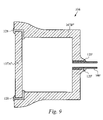
- FIG. 9 illustrates a housing and a fluid tube sealed according to a simultaneous multiple compression sealing process.
- FIG. 1 illustrates a block diagram of a hermetic closed loop fluid system 100 in accordance with the present invention.
- the hermetic closed loop system 100 preferably cools an electronic device 99 such as a computer microprocessor.
- the fluid system 100 preferably includes at least one pump 106 , at least one heat exchanger 102 and at least one heat rejector 104 .
- the heat exchanger 102 is coupled to the heat rejector 104 by one or more fluid lines 108 .
- the heat rejector 104 is coupled to the pump 106 by one or more fluid lines 108 .
- the pump 106 is coupled to the heat exchanger 102 by one or more fluid lines 108 .
- the present system 100 is not limited to the components shown in FIG. 1 and alternatively includes other components and devices.
- the purpose of the hermetic closed fluid loop 100 shown in FIG. 1 is to capture heat generated by the electronic device 99 .
- the fluid within the heat exchanger 102 performs thermal exchange by conduction with the heat produced via the electronic device 99 .
- the fluid within the system 100 can be based on combinations of organic solutions, including but not limited to propylene glycol, ethanol and isopropanol (IPA).
- IPA isopropanol
- the fluid used in the present system 100 also preferably exhibits a low freezing temperature and has anti-corrosive characteristics.
- the fluid exhibits single phase flow while circulating within the system 100 .
- the fluid is heated to a temperature to exhibit two phase flow, wherein the fluid undergoes a phase transition from liquid to a vapor or liquid/vapor mix.
- the amount of fluid which escapes from the system over a given time depends on whether the fluid exhibits single or two phase characteristics.
- the heated fluid flows out from the heat exchanger 102 via the fluid lines 108 to the heat rejector 104 .
- the heat rejector 104 transfers the heat from the heated fluid to the surrounding air, thereby cooling the heated fluid to a temperature which allows the fluid to effectively cool the heat source 99 as it re-enters the heat exchanger 102 .
- the pump 106 pumps the fluid from the heat rejector 104 to the heat exchanger 102 as well as circulates the fluid through the cooling system 100 via the fluid lines 108 .
- the cooling system 100 thereby provides efficient capture and movement of the heat produced by the electronic device 99 .
- the pump 106 is an electroosmotic type pump shown and described in co-pending patent application Ser. No. 10/669,495, filed Sep. 23, 2003, which is hereby incorporated by reference.
- the heat exchanger 102 is shown and described in co-pending patent application Ser. No. 10/680,584, filed Oct. 6, 2003, which is hereby incorporated by reference.
- the heat rejector 104 is shown and described in co-pending patent application Ser. No. 10/699,505, filed Oct. 30, 2003, which is hereby incorporated by reference.
- any type of heat rejector is alternatively contemplated.
- the closed loop fluid system 100 of the present invention is hermetic and is configured to minimize loss of the fluid in the system and to maintain a total volume of the fluid in the system above a predetermined quantity over a desired amount of time.
- an acceptable amount of fluid loss, or acceptable threshold of hermeticity, in the present system 100 is defined based on variety of factors including, but not limited to, the type and characteristics as well as the expected life of the product which utilizes the present system 100 within.
- the life of the product depends on the nature of the product as well as other factors. However, for illustration purposes only, the life of the product herein is designated as 10 years, although any amount of time is alternatively contemplated.
- the present system 100 achieves a hermetic environment by utilizing components which comprise the desired dimensions and materials to minimize the fluid loss over a predetermined amount of time.
- components include, but are not limited to, the heat exchanger 102 , heat rejector 104 , pump 106 and fluid lines 108 ( FIG. 1 ). Consideration must also be made for the interconnections between each of the components and the potential fluid loss resulting therefrom.
- liquid fluid For the fluid system of the present invention 100 to properly operate, a sufficient amount of liquid fluid must be available at the inlet of the pump 106 at all times to allow the pump 106 to continue pumping the fluid throughout the system 100 .
- the total amount of liquid volume depends on a variety of factors including, but not limited to, the type of pump, heat exchanger and heat condensor used, whether the heat-transfer process involves single-phase or two-phase flow, and the materials used.
- the closed-loop fluid system for electronic cooling will lose less than 0.89 gm of fluid/year.
- the closed loop fluid system for electronics cooling will lose less than 1.25 gm of fluid/year.
- the closed-loop fluid system for electronics cooling will lose less than 2.5 gm of fluid/year. It should be noted that these values are for illustration purposes only, and the present invention is not limited to these values or parameters.
- the fluid escapes from the fluid system 100 by permeation of the components used. Diffusion occurs when a single phase or two phase fluid travels through a material from one side to the other side over a period of time. Within the setting of a closed loop fluid system, the fluid escapes from the system to the surroundings of the system by “leaking” through the actual material of the components.
- the rate of diffusion of the fluid through the material is dependent on the permeability characteristics of the material, which is a function of temperature. In addition, the rate of diffusion of the fluid is dependent on the surface area and thickness dimensions of the components which enclose the fluid.
- fluid within a fluid tube 108 having a certain diameter and thickness will diffuse through the tube 108 at a slower rate than through a fluid tube 108 of the same material having a larger diameter and a smaller thickness.
- the pressure differential between the pressure inside and outside of the component affects the rate of diffusion of the fluid.
- the pressure from a two phase fluid, or single phase fluid with a finite amount of vapor is capable of diffusing the vapor into and through the material of the component. Therefore, the dimensions of the component, the pressure of the fluid, as well as the material of the component determine the rate at which the fluid diffuses or escapes from the system 100 .
- the pressure versus temperature relationship of a two phase fluid is a factor in determining the liquid-vapor transition temperature which determines the operating temperature of the fluid in the cooling loop system 100 .
- the overall pressure within system 100 is reduced to the desired level.
- the pressure differential will then tend to cause the vapor within the component to diffuse through the component material to the surrounding area to equalize the pressure between the interior of the component and the surroundings of the component.
- the permeability of vapor through the walls of the component is defined in terms of cubic centimeters (cm 3 ) of vapor at standard temperature and pressure (STP) which is diffused per unit area of a given thickness and pressure difference.
- the interior of the system is at a very low pressure, and there is a gas species in the surrounding atmosphere at a relatively high pressure
- diffusion can allow movement of gas from the outside to the inside.
- a cooling loop filled with fluid and some O 2 and H 2 gas will have essentially no N 2 gas on the inside.
- the surrounding air contains a relatively high fraction of N 2 gas, so that the partial pressure of N 2 on the outside of the loop might be as much as 70% of an atmosphere.
- 70% of an atmosphere is a net pressure difference forcing diffusion of nitrogen from the outside to the inside.
- the system is designed to account for the gas species in the surrounding air as well as for the gas species trapped within the loop.
- the hermetic closed loop fluid system 100 of the present invention utilizes components which are made of low permeable materials and configures the components according to proper dimensions thereby minimizing loss of fluid over the desired operating life of the system 100 .
- the fittings and coupling members used in the present system 100 are made of materials having a low permeability. Therefore, the components, fittings, and coupling members within the system 100 of the present invention are preferably made of ceramics, glass and/or metals.
- the components are made of any other appropriate material which allows a fluid permeability rate of less than 0.01 grams millimeters per meter squared per day (gm-mm/m 2 -day).
- Such appropriate materials include, but are not limited to, metal, ceramic, glass, plastic, metalized plastic, and any combination thereof.
- the amount of a single phase fluid which permeates through a component being made of a material having a permeability rate of 0.01 gm-mm/m 2 -day in one year depends on the dimensions of the component. For instance, a component in the system 100 having a total surface area of 100 cm 2 and a wall thickness of 1 mm will have a fluid loss of less than 0.4 cm 3 in a ten year period. It should be noted that these dimensions are exemplary and any other length, width and thickness dimensions ( FIG. 2 ) are contemplated. It should also be noted that the dimensions and rates described herein are approximations.
- Table 1 lists the approximate permeability rates of Hydrogen, Oxygen, and Nitrogen through various materials.
- a water-filled system includes a surface area of 100 cm 2 , and a thickness of 1 mm.
- the permeation rate for water vapor through Polyethylene (HDPE) is about 3 cm 3 of water vapor at STP per day. This is approximately equivalent to 3 ⁇ 10 ⁇ 3 cm 3 of liquid water loss per day, or about 1 mL loss per year. If any of the components of a polymer-based cooling loop are composed of silicone or polybutadiene rubber, these loss rates can be 10–100 times worse.
- the ability for the fluid to diffuse through the inner walls of the components, which are made of the preferred materials discussed above, is significantly lower than through a plastic, silicone or rubber material.
- the permeability of hydrogen gas through copper at room temperature is approximately 1 ⁇ 10 ⁇ 3 cm 3 (STP)-mm/m 2 /day. Therefore, a component, such as the fluid tube 108 , made of copper which has a surface area of 100 cm 2 area and being 1 mm thick, will allow a permeation or leakage rate of approximately 0.003 cm 3 of hydrogen gas/year. Over a 10 year period, the copper fluid tube 108 will allow less than 0.03 cm 3 of hydrogen to escape into or out of the system 100 .
- These calculations are all based on a situation with an atmosphere (100 kPa) of H 2 pressure on one side of the barrier and no H 2 on the other side, which is an extreme case.
- the permeability rate of nitrogen gas through the 7740 glass material is between 1 and 2 ⁇ 10 ⁇ 16 cm 2 /sec, which converts to about 1 ⁇ 10 ⁇ 6 cm 3 (STP)-mm/m 2 /day.
- STP 1 ⁇ 10 ⁇ 6 cm 3
- a component in the fluid system 100 made of 7740 glass which has a surface area of 100 cm 2 and a thickness of 1 mm will allow less than 4 ⁇ 10 ⁇ 5 cm 3 of STP nitrogen into or out of the system in a year, and less than 4 ⁇ 10 ⁇ 4 cm 3 of STP nitrogen into or out of the system in 10 years.
- nitrogen permeability in polyethylene can be as high as 100 cm 3 (STP)-mm/m 2 -day.
- the present system 100 operates with an internal volume of 100 cm 3 of fluid, 90% of which is liquid and 10% of which is vapor, the permeability value of the polyethylene would allow almost all of the pressurized vapor to diffuse through the walls of the components in a short amount of time.
- nitrogen gas will diffuse through the walls of a component in the present system 100 made of 7740 glass 10 7 times slower than if the component was made of polyethylene.
- polyester has a permeability of approximately 1 cm 3 (STP)-mm/m 2 /day for oxygen and approximately 0.4 cm 3 (STP)-mm/m 2 /day for nitrogen
- EVOH has a permeability of approximately 0.003 cm 3 (STP)-mm/m 2 /day for nitrogen and approximately 0.01 cm 3 (STP)-mm/m 2 /day for oxygen.
- STP Sevron Phillips Chemical Company
- polyester has a permeability of approximately 0.003 cm 3 (STP)-mm/m 2 /day for nitrogen and approximately 0.01 cm 3 (STP)-mm/m 2 /day for oxygen.
- EVOH and polyester are generally a preferred choice of organic material used in other sealing environments, such as for food packaging, they are inadequate for hermetic cooling loop applications.
- the permeability numbers are about 1000 times higher for the organic materials.
- the much larger permeability numbers for hydrogen in the organic materials make them unacceptable for hermetic loop applications.
- the permeability of hydrogen for both polyester and EVOH are 50 times or more worse than for nitrogen and oxygen, and would allow very significant hydrogen diffusion.
- Very thin films of aluminum are currently used in food packaging, and are known to significantly reduce the water vapor permeation through mylar films.
- 100–300 angstroms of aluminum reduces the permeation rate through a plastic film to less than 5 (cm 3 (STP) mm/m 2 /day), which is almost 10 times better than any mm-thickness of any of the polymer films in Table 1, and this residual permeation rate is attributed to defects in the film.
- Macroscopic metal structures do not exhibit any measurable permeation of water vapor or any atmospheric constituents.
- the above permeability values for polyethylene, polyester and EVOH are provided at Standard Temperature and Pressure.
- closed loop fluid system usually operate at temperatures and pressure above the STP temperature range, whereby the permeability values increase with increased temperatures. Therefore, the vapor within a system utilizing polyethylene, polyester or EVOH components will diffuse through the components at faster rate than the figures mentioned herein.
- the type of fluid used within the closed loop system 100 is a design decision, and therefore, the diffusion species contemplated by the present invention can extend beyond nitrogen, oxygen, and hydrogen, as shown in Table 1. Where other diffusion species are contemplated, the choice of barrier material is preferably determined as to minimize diffusion of the diffusion species through the barrier material.
- the components in the system 100 of the present invention which are made of metal are preferably sealed by soldering, welding, brazing, or crimping.
- Components used in the present system 100 which are made of glass parts are preferably sealed with sealing glass, solder or by fusing.
- Components used in the present system 100 which are made of ceramic material are preferably sealed with ceramic-based epoxy or sealed by soldering.
- FIG. 3 illustrates a first interconnection between the fluid tube 108 and a component port 110 .
- the component port 110 comprises the inlet port of the pump housing 106 .
- the fluid tubes 108 are preferably made of Copper, whereby each Copper tube 108 is preferably coupled to each component port 110 with a sealing collar 112 .
- the fluid tubes 108 are made of another appropriate material having a desired low permeability.
- the inlet fluid tube 108 is coupled to the inlet fluid port 110 of the pump 106 , whereby the sealing collar 112 is positioned between the inner surface of the fluid tube 108 and the inner surface of the fluid port 110 .
- the sealing collar 112 is preferably made of Tungsten or any other appropriate material which has a coefficient of thermal expansion (CTE) that closely matches the material of the fluid port 110 . Unless the pump 106 is made of the same material as the fluid tube 108 , the CTE of the sealing collar 112 material will probably not match that of the fluid tube 108 material. However, the sealing collar 112 is preferably selected to have an appropriate ductility to maintain a seal with the fluid tube 108 material regardless of the amount of expansion or contraction experienced by the fluid tube 108 .
- CTE coefficient of thermal expansion
- sealing collar 112 is described in relation to the inlet port 110 of the pump 106 , it is apparent to one skilled in the art that the sealing collar 112 is also preferably utilized between the fluid tubes and the inlet and outlet ports of the other components in the present system 100 .
- the sealing collar 112 is preferably coupled to the fluid hose 108 and the inlet port 110 using compression fitting.
- Compression fitting is preferably accomplished by heating the pump housing 107 , thereby increasing the size of the inlet port 110 .
- a first end of the sealing collar 112 is then placed in the expanded inlet port 110 , and the housing 107 is allowed to cool, and contract, forming a seal around the sealing collar 112 .
- the fluid tube 108 is heated, whereby the fluid tube 108 expands to allow a slip fit over a second end of the sealing collar 112 .
- the sealing collar 112 is then inserted in the expanded fluid tube 108 , and the fluid tube 108 is allowed to cool, and contract, forming a seal around the sealing collar 112 .
- the compression fitting of the inlet port 110 and the fluid tube 108 to the sealing collar 112 can be accomplished by first coupling the sealing collar 112 to the inlet port 110 and then coupling the sealing collar 112 to the fluid tube 108 , as described above, or by reversing the steps.
- the sealing collar 112 can be coupled to the inlet port 110 and the fluid tube 108 simultaneously, that is by heating both the housing 107 and the fluid tube 108 , and then inserting the first end of the sealing collar 112 in the expanded inlet port 110 and inserting the second end of the sealing collar 112 in the expanded fluid hose 108 .
- the housing 107 and the fluid tube 108 are then both allowed to cool, and contract, forming a seal around the first and second ends of the sealing collar 112 .
- FIG. 4 illustrates a second interconnection between the fluid tube 108 and a component port 110 .
- the fluid tube 108 is coupled directly to the inlet port 110 .
- the interconnection between the fluid tube 108 and the inlet port 110 is preferably accomplished by compression fitting, whereby the housing 107 is heated to a sufficiently high temperature to expand the inlet port 110 .
- the fluid tube 108 is then inserted into the expanded inlet port 110 and held in place while the housing 107 cools. As the housing cools, it contracts thermally, and the inlet port 110 also contracts, eventually forming a compression seal around the fluid tube 108 .
- the fluid tube 108 is comprised of a sufficiently ductile material such that when the inlet port 110 contracts around the fluid tube 108 , the fluid tube 108 does not crack or break.
- the amount of compression can be controlled to avoid cracking the housing 107 yet still cause some compression of the fluid tube 108 .
- FIG. 5 illustrates a third interconnection between the fluid tube 108 and a component port 110 .
- a sealing material 120 is placed between the inner surface of the inlet port 110 and the outer surface of the fluid tube 108 .
- the fluid tube 108 is preferably coupled to the inlet port 110 by compression fitting, as described above in relation to FIG. 4 .
- the permeation rate of the sealing material is proportional to the seal area divided by the seal length.
- the seal area is approximately equal to the radius of fluid tube 108 times the width W of the sealing material 120 times 2 times Pi.
- the seal length is the length L of the sealing material 120 .
- the sealing material 120 is preferably solder, although sealing glass or epoxy can also be used. Alternatively, any sealing material with a permeability rate that provides a hermetic seal with a diffusion rate within a predetermined range can be used. Solder forms a particular effective hermetic seal. Solder can be applied to metals that have had proper surface treatments, glasses, and ceramics. When solder is applied to glass and ceramic, the glass and ceramic are preferably metalized prior to applying the solder. Solder melting temperatures can be selected over a broad range. A series of different solders with successively lower melting temperatures can also be used to allow a sequential sealing of joints. In addition to providing a hermetic seal, solder is also advantageous because it's ductility allows some mismatch between the thermal expansion coefficients of the housing, solder, and tube materials.
- epoxies In general, epoxies have marginal or poor permeabilities for vapor diffusion, and are not a preferable choice for a joint material.
- the area/length ratio of the epoxy can be very low, so that there is very little exposed area and a very long path for diffusion from the inside to the outside of the component. If such a configuration is used, the epoxy permeability is acceptable.
- Sealing glasses are also known to have very low permeabilities, and can be used as hermetic sealing compounds in joints between metals and glass.
- Sealing glass is generally a brittle material, so this kind of arrangement requires that the thermal expansion coefficients of the housing, tube and sealing glass are similar.
- the sealing glass generally hardens at a relatively high temperature, e.g. greater than 400 degrees Celsius, so the thermal expansion of the housing, tube, and sealing glass are preferably similar over the range of temperatures from the seal temperature to the use temperatures.
- There are a wide variety of sealing glasses with varying thermal expansion coefficients and there are wide varieties of metal tube materials which have thermal expansion coefficients over a broad range. Careful selection of the tube material and the seal material can allow use with most glass or ceramic housing materials.
- FIG. 6 illustrates a fourth interconnection between the fluid tube 108 and a component port 110 .
- the width of the inlet port 110 is not constant through the entire width of the housing 107 . Instead, the width of the inlet port 110 narrows at some point within the housing 107 , thereby creating a stop.
- the fluid tube 108 is inserted into the inlet port 110 to a point that is short of the stop by an end gap distance g.
- a sealing material 122 forms a seal between the fluid tube 108 and housing 107 , where the sealing material 122 also forms a seal of end gap width g between the end of the fluid tube and the stop within the housing 107 . Forming the stop and providing the sealing material 122 with a small gap distance g acts to reduce the exposed surface area of the sealing material 122 , which reduces diffusion.
- a sealing material can also be used in the case where the fluid tube 108 is coupled to the inlet port 110 via the sealing collar 112 , as described above in relation to FIG. 3 .
- the sealing material can be placed between the outer surface of the first end of the sealing collar 112 and the inner surface of the inlet port 110 .
- the sealing material can also be placed between the outer surface of the second end of the sealing collar 112 and the inner surface of the fluid tube 108 . It is understood that the sealing material can be used to couple the sealing collar 112 to the inlet port 110 , or to couple the sealing collar 112 to the fluid tube 108 , or a combination of the two.
- the housing 107 is preferably comprised of a material with a thermal expansion coefficient sufficiently large such that heating the housing 107 to a relatively high temperature, e.g. 400 degrees Celsius or higher, sufficiently expands the inlet port 110 to allow insertion of the fluid tube 108 , the sealing collar 112 , and/or the sealing material 120 , 122 .
- FIG. 8 illustrates a second housing interconnect in which the end portion of the right half portion 107 B′ bends around a left half portion 107 A′.
- the left half portion 107 A′ is coupled to the right half portion 107 B′ by a sealing material 126 .
- the gap g formed where the right half portion 107 B′ bends around the left half portion 107 A′ is preferably minimized thereby reducing the exposed surface area of the sealing material 126 , which reduces diffusion.
- the two halves 107 A′ and 107 B′ are preferably coupled together using a compression seal.
- the housing 107 can be comprised of more than two separate pieces, which can be sealed together as described above. Each piece of the housing 107 can be similarly configured, as in FIG. 7 , uniquely configured, or a combination thereof.
- the portion of the housing 107 that comprises the inlet port 110 preferably extends beyond the outer surface of the remaining portion of the housing 107 .
- the inlet portion 110 is approximately flush with the housing 107 .
- the seal length L of the sealing material is smaller than the preferred case where the inlet port 110 extends outward from the remaining portion of the housing 107 .
- FIG. 9 illustrates an exemplary pump configuration in which a right half portion 107 B′′ and a left half portion 107 A′′ of the housing 107 can be sealed together simultaneously with the sealing of a fluid tube 108 ′ and the right half portion 107 B′′.
- the sealing is preferably performed using a compression seal where the right half portion 107 B′′ is pre-heated to expand.
- the fluid tube 108 ′ and sealing material 120 ′ are then inserted within an opening in the right half portion 107 B′′, and the left half portion 107 A′′ and sealing material 128 are properly aligned with the right half portion 107 B′′.
- a compression seal is formed between the fluid tube 108 ′ and the right half portion 107 B′′, and the left half portion 107 A′′ and the right half portion 107 B′′.
- the sealing material 120 ′, 128 is placed on the fluid tube 108 and the left half portion 107 A′′ prior to placing in contact with the right half portion 107 B′′.
- the sealing material 120 ′, 128 melts and cures when contacted by the heated right half portion 107 B′′.
Landscapes
- Physics & Mathematics (AREA)
- Condensed Matter Physics & Semiconductors (AREA)
- General Physics & Mathematics (AREA)
- Engineering & Computer Science (AREA)
- Computer Hardware Design (AREA)
- Microelectronics & Electronic Packaging (AREA)
- Power Engineering (AREA)
- Cooling Or The Like Of Electrical Apparatus (AREA)
Abstract
Description
| Permeability Coefficient | ||
| Barrier Material | Diffusing Species | (cm3 (STP)-mm/m2/day) |
| Polyethylene (HDPE) | Nitrogen | 14 |
| Polyethylene (HDPE) | Hydrogen | 126 |
| Polyethylene (HDPE) | Oxygen | 40 |
| Polyethylene (HDPE) | Water Vapor | 300 |
| Polyester (PET) | Nitrogen | 0.4 |
| Polyester (PET) | Hydrogen | 40 |
| Polyester (PET) | Oxygen | 1.1 |
| Polyester (PET) | Water Vapor | 250 |
| EVOH | Nitrogen | 0.003 |
| EVOH | Hydrogen | 1 |
| EVOH | Oxygen | 0.01 |
| EVOH | Water Vapor | 300 |
| Polyimide (Kapton) | Nitrogen | 30 |
| Polyimide (Kapton) | Hydrogen | 1500 |
| Polyimide (Kapton) | |
100 |
| Polyimide (Kapton) | Water Vapor | 300 |
| Copper | Hydrogen | <1 × 10⁻³ |
| Kovar | Hydrogen | <1 × 10⁻² |
| Aluminum | Hydrogen | <1 × 10⁻⁵ |
| 7740 glass | Nitrogen | <1 × 10⁻⁶ |
| Silicone Rubber | Water Vapor | 2,000 |
| Polybutadiene Rubber | Water Vapor | 20,000 |
Claims (66)
Priority Applications (1)
| Application Number | Priority Date | Filing Date | Title |
|---|---|---|---|
| US10/769,717 US7021369B2 (en) | 2003-07-23 | 2004-01-29 | Hermetic closed loop fluid system |
Applications Claiming Priority (2)
| Application Number | Priority Date | Filing Date | Title |
|---|---|---|---|
| US48973003P | 2003-07-23 | 2003-07-23 | |
| US10/769,717 US7021369B2 (en) | 2003-07-23 | 2004-01-29 | Hermetic closed loop fluid system |
Publications (2)
| Publication Number | Publication Date |
|---|---|
| US20050016715A1 US20050016715A1 (en) | 2005-01-27 |
| US7021369B2 true US7021369B2 (en) | 2006-04-04 |
Family
ID=34083575
Family Applications (1)
| Application Number | Title | Priority Date | Filing Date |
|---|---|---|---|
| US10/769,717 Expired - Fee Related US7021369B2 (en) | 2003-07-23 | 2004-01-29 | Hermetic closed loop fluid system |
Country Status (1)
| Country | Link |
|---|---|
| US (1) | US7021369B2 (en) |
Cited By (24)
| Publication number | Priority date | Publication date | Assignee | Title |
|---|---|---|---|---|
| US20060044759A1 (en) * | 2004-08-26 | 2006-03-02 | Chebiam Ramanan V | Electroosmotic pump apparatus that generates low amount of hydrogen gas |
| US20070193642A1 (en) * | 2006-01-30 | 2007-08-23 | Douglas Werner | Tape-wrapped multilayer tubing and methods for making the same |
| US20070235167A1 (en) * | 2006-04-11 | 2007-10-11 | Cooligy, Inc. | Methodology of cooling multiple heat sources in a personal computer through the use of multiple fluid-based heat exchanging loops coupled via modular bus-type heat exchangers |
| US20070262286A1 (en) * | 2006-05-12 | 2007-11-15 | Je-Young Chang | Coolant capable of enhancing corrosion inhibition, system containing same, and method of manufacturing same |
| US20070267188A1 (en) * | 2006-05-18 | 2007-11-22 | Centipede Systems, Inc. | Method and apparatus for setting and controlling temperature |
| WO2008024146A1 (en) * | 2006-08-24 | 2008-02-28 | Microfluidic Systems, Inc. | A liquid impingement unit |
| US20090046429A1 (en) * | 2007-08-07 | 2009-02-19 | Werner Douglas E | Deformable duct guides that accommodate electronic connection lines |
| US20090225515A1 (en) * | 2008-03-10 | 2009-09-10 | James Hom | Thermal bus or junction for the removal of heat from electronic components |
| US20100032143A1 (en) * | 2008-08-05 | 2010-02-11 | Cooligy Inc. | microheat exchanger for laser diode cooling |
| US7806168B2 (en) | 2002-11-01 | 2010-10-05 | Cooligy Inc | Optimal spreader system, device and method for fluid cooled micro-scaled heat exchange |
| US7836597B2 (en) | 2002-11-01 | 2010-11-23 | Cooligy Inc. | Method of fabricating high surface to volume ratio structures and their integration in microheat exchangers for liquid cooling system |
| US20110186270A1 (en) * | 2010-02-01 | 2011-08-04 | Suna Display Co. | Heat transfer device with anisotropic heat dissipating and absorption structures |
| US8157001B2 (en) | 2006-03-30 | 2012-04-17 | Cooligy Inc. | Integrated liquid to air conduction module |
| US20120305218A1 (en) * | 2011-06-01 | 2012-12-06 | Benjamin Masefield | Heat Sink |
| US8414847B2 (en) | 2008-09-30 | 2013-04-09 | Forced Physics, Llc | Method and apparatus for control of fluid temperature and flow |
| US8464781B2 (en) | 2002-11-01 | 2013-06-18 | Cooligy Inc. | Cooling systems incorporating heat exchangers and thermoelectric layers |
| US8517722B1 (en) * | 2010-05-12 | 2013-08-27 | Elemental Scientific, Inc. | Torch assembly |
| US8602092B2 (en) | 2003-07-23 | 2013-12-10 | Cooligy, Inc. | Pump and fan control concepts in a cooling system |
| US9179575B1 (en) * | 2012-03-13 | 2015-11-03 | Rockwell Collins, Inc. | MEMS based device for phase-change autonomous transport of heat (PATH) |
| US9297571B1 (en) | 2008-03-10 | 2016-03-29 | Liebert Corporation | Device and methodology for the removal of heat from an equipment rack by means of heat exchangers mounted to a door |
| US20160128234A1 (en) * | 2014-10-30 | 2016-05-05 | Fujitsu Limited | Cooling device and electronic apparatus |
| US9709324B1 (en) * | 2012-11-09 | 2017-07-18 | Rockwell Collins, Inc. | Liquid cooling with parasitic phase-change pumps |
| US20220141997A1 (en) * | 2019-03-11 | 2022-05-05 | Apr Technologies Ab | Cooling of electronic components with an electrohydrodynamic flow unit |
| US20230422441A1 (en) * | 2022-06-25 | 2023-12-28 | EvansWerks, Inc. | Cooling system and methods |
Families Citing this family (6)
| Publication number | Priority date | Publication date | Assignee | Title |
|---|---|---|---|---|
| CN1980558B (en) * | 2005-12-09 | 2011-09-28 | 鸿富锦精密工业(深圳)有限公司 | Liquid-cooling type radiating combination and liquid-cooling radiating apparatus |
| US7954332B2 (en) * | 2007-01-19 | 2011-06-07 | Alkhorayef Petroleum Company | Temperature control systems and methods |
| US9238398B2 (en) * | 2008-09-25 | 2016-01-19 | B/E Aerospace, Inc. | Refrigeration systems and methods for connection with a vehicle's liquid cooling system |
| TWI506238B (en) * | 2009-12-29 | 2015-11-01 | Foxconn Tech Co Ltd | Micro liquid cooling device |
| JP6555081B2 (en) * | 2015-10-30 | 2019-08-07 | 富士通株式会社 | Sealed loop circulating liquid cooling device and electronic equipment |
| WO2023023095A1 (en) * | 2021-08-16 | 2023-02-23 | Carnegie Mellon University | System and method for an interaction surface with shape-changing tactile elements |
Citations (103)
| Publication number | Priority date | Publication date | Assignee | Title |
|---|---|---|---|---|
| US596062A (en) | 1897-12-28 | Device for preventing bursting of freezing pipes | ||
| US2273505A (en) | 1942-02-17 | Container | ||
| US3654988A (en) | 1970-02-24 | 1972-04-11 | American Standard Inc | Freeze protection for outdoor cooler |
| US3817321A (en) | 1971-01-19 | 1974-06-18 | Bosch Gmbh Robert | Cooling apparatus semiconductor elements, comprising partitioned bubble pump, separator and condenser means |
| US3823572A (en) | 1973-08-15 | 1974-07-16 | American Air Filter Co | Freeze protection device in heat pump system |
| US3923426A (en) | 1974-08-15 | 1975-12-02 | Alza Corp | Electroosmotic pump and fluid dispenser including same |
| US3929154A (en) | 1974-07-29 | 1975-12-30 | Frank E Goodwin | Freeze protection apparatus |
| US4109707A (en) | 1975-07-02 | 1978-08-29 | Honeywell Information Systems, Inc. | Fluid cooling systems for electronic systems |
| US4194559A (en) | 1978-11-01 | 1980-03-25 | Thermacore, Inc. | Freeze accommodating heat pipe |
| US4211208A (en) | 1976-12-24 | 1980-07-08 | Deutsche Forschungs- Und Versuchsanstalt Fur Luft- Und Raumfahrt E.V. | Container for a heat storage medium |
| US4248295A (en) | 1980-01-17 | 1981-02-03 | Thermacore, Inc. | Freezable heat pipe |
| US4485429A (en) | 1982-06-09 | 1984-11-27 | Sperry Corporation | Apparatus for cooling integrated circuit chips |
| US4561040A (en) | 1984-07-12 | 1985-12-24 | Ibm Corporation | Cooling system for VLSI circuit chips |
| US4664181A (en) | 1984-03-05 | 1987-05-12 | Thermo Electron Corporation | Protection of heat pipes from freeze damage |
| US4866570A (en) | 1988-08-05 | 1989-09-12 | Ncr Corporation | Apparatus and method for cooling an electronic device |
| US4894709A (en) | 1988-03-09 | 1990-01-16 | Massachusetts Institute Of Technology | Forced-convection, liquid-cooled, microchannel heat sinks |
| US4896719A (en) | 1988-05-11 | 1990-01-30 | Mcdonnell Douglas Corporation | Isothermal panel and plenum |
| US4908112A (en) | 1988-06-16 | 1990-03-13 | E. I. Du Pont De Nemours & Co. | Silicon semiconductor wafer for analyzing micronic biological samples |
| US5009760A (en) | 1989-07-28 | 1991-04-23 | Board Of Trustees Of The Leland Stanford Junior University | System for measuring electrokinetic properties and for characterizing electrokinetic separations by monitoring current in electrophoresis |
| US5043797A (en) * | 1990-04-03 | 1991-08-27 | General Electric Company | Cooling header connection for a thyristor stack |
| US5058627A (en) | 1989-04-10 | 1991-10-22 | Brannen Wiley W | Freeze protection system for water pipes |
| US5070040A (en) | 1990-03-09 | 1991-12-03 | University Of Colorado Foundation, Inc. | Method and apparatus for semiconductor circuit chip cooling |
| US5088005A (en) | 1990-05-08 | 1992-02-11 | Sundstrand Corporation | Cold plate for cooling electronics |
| US5096388A (en) | 1990-03-22 | 1992-03-17 | The Charles Stark Draper Laboratory, Inc. | Microfabricated pump |
| US5099311A (en) | 1991-01-17 | 1992-03-24 | The United States Of America As Represented By The United States Department Of Energy | Microchannel heat sink assembly |
| US5099910A (en) | 1991-01-15 | 1992-03-31 | Massachusetts Institute Of Technology | Microchannel heat sink with alternating flow directions |
| US5125451A (en) | 1991-04-02 | 1992-06-30 | Microunity Systems Engineering, Inc. | Heat exchanger for solid-state electronic devices |
| US5131233A (en) | 1991-03-08 | 1992-07-21 | Cray Computer Corporation | Gas-liquid forced turbulence cooling |
| US5203401A (en) | 1990-06-29 | 1993-04-20 | Digital Equipment Corporation | Wet micro-channel wafer chuck and cooling method |
| US5218515A (en) | 1992-03-13 | 1993-06-08 | The United States Of America As Represented By The United States Department Of Energy | Microchannel cooling of face down bonded chips |
| US5219278A (en) | 1989-11-10 | 1993-06-15 | Westonbridge International, Ltd. | Micropump with improved priming |
| US5232047A (en) | 1991-04-02 | 1993-08-03 | Microunity Systems Engineering, Inc. | Heat exchanger for solid-state electronic devices |
| US5239200A (en) | 1991-08-21 | 1993-08-24 | International Business Machines Corporation | Apparatus for cooling integrated circuit chips |
| US5263251A (en) | 1991-04-02 | 1993-11-23 | Microunity Systems Engineering | Method of fabricating a heat exchanger for solid-state electronic devices |
| US5309319A (en) | 1991-02-04 | 1994-05-03 | International Business Machines Corporation | Integral cooling system for electric components |
| US5317805A (en) | 1992-04-28 | 1994-06-07 | Minnesota Mining And Manufacturing Company | Method of making microchanneled heat exchangers utilizing sacrificial cores |
| US5325265A (en) | 1988-11-10 | 1994-06-28 | Mcnc | High performance integrated circuit chip package |
| US5336062A (en) | 1990-02-27 | 1994-08-09 | Fraunhofer-Gesellschaft Zur Forderung Der Angewandten Forschung E.V. | Microminiaturized pump |
| US5380956A (en) | 1993-07-06 | 1995-01-10 | Sun Microsystems, Inc. | Multi-chip cooling module and method |
| US5383340A (en) | 1994-03-24 | 1995-01-24 | Aavid Laboratories, Inc. | Two-phase cooling system for laptop computers |
| US5427174A (en) | 1993-04-30 | 1995-06-27 | Heat Transfer Devices, Inc. | Method and apparatus for a self contained heat exchanger |
| US5436793A (en) | 1993-03-31 | 1995-07-25 | Ncr Corporation | Apparatus for containing and cooling an integrated circuit device having a thermally insulative positioning member |
| US5514906A (en) | 1993-11-10 | 1996-05-07 | Fujitsu Limited | Apparatus for cooling semiconductor chips in multichip modules |
| US5544696A (en) | 1994-07-01 | 1996-08-13 | The United States Of America As Represented By The Secretary Of The Air Force | Enhanced nucleate boiling heat transfer for electronic cooling and thermal energy transfer |
| US5548605A (en) | 1995-05-15 | 1996-08-20 | The Regents Of The University Of California | Monolithic microchannel heatsink |
| US5579828A (en) | 1996-01-16 | 1996-12-03 | Hudson Products Corporation | Flexible insert for heat pipe freeze protection |
| US5585069A (en) | 1994-11-10 | 1996-12-17 | David Sarnoff Research Center, Inc. | Partitioned microelectronic and fluidic device array for clinical diagnostics and chemical synthesis |
| US5641400A (en) | 1994-10-19 | 1997-06-24 | Hewlett-Packard Company | Use of temperature control devices in miniaturized planar column devices and miniaturized total analysis systems |
| US5692558A (en) | 1996-07-22 | 1997-12-02 | Northrop Grumman Corporation | Microchannel cooling using aviation fuels for airborne electronics |
| US5696405A (en) | 1995-10-13 | 1997-12-09 | Lucent Technologies Inc. | Microelectronic package with device cooling |
| US5703536A (en) | 1996-04-08 | 1997-12-30 | Harris Corporation | Liquid cooling system for high power solid state AM transmitter |
| US5704416A (en) | 1993-09-10 | 1998-01-06 | Aavid Laboratories, Inc. | Two phase component cooler |
| US5727618A (en) | 1993-08-23 | 1998-03-17 | Sdl Inc | Modular microchannel heat exchanger |
| US5759014A (en) | 1994-01-14 | 1998-06-02 | Westonbridge International Limited | Micropump |
| US5763951A (en) * | 1996-07-22 | 1998-06-09 | Northrop Grumman Corporation | Non-mechanical magnetic pump for liquid cooling |
| US5801442A (en) | 1996-07-22 | 1998-09-01 | Northrop Grumman Corporation | Microchannel cooling of high power semiconductor devices |
| US5800690A (en) | 1996-07-03 | 1998-09-01 | Caliper Technologies Corporation | Variable control of electroosmotic and/or electrophoretic forces within a fluid-containing structure via electrical forces |
| US5835345A (en) | 1996-10-02 | 1998-11-10 | Sdl, Inc. | Cooler for removing heat from a heated region |
| US5836750A (en) | 1997-10-09 | 1998-11-17 | Honeywell Inc. | Electrostatically actuated mesopump having a plurality of elementary cells |
| US5858188A (en) | 1990-02-28 | 1999-01-12 | Aclara Biosciences, Inc. | Acrylic microchannels and their use in electrophoretic applications |
| US5869004A (en) | 1997-06-09 | 1999-02-09 | Caliper Technologies Corp. | Methods and apparatus for in situ concentration and/or dilution of materials in microfluidic systems |
| US5870823A (en) | 1996-11-27 | 1999-02-16 | International Business Machines Corporation | Method of forming a multilayer electronic packaging substrate with integral cooling channels |
| US5874795A (en) | 1995-12-28 | 1999-02-23 | Japan Servo Co., Ltd | Multi-phase permanent-magnet type electric rotating machine |
| US5876655A (en) | 1995-02-21 | 1999-03-02 | E. I. Du Pont De Nemours And Company | Method for eliminating flow wrinkles in compression molded panels |
| US5880017A (en) | 1994-08-08 | 1999-03-09 | Hewlett-Packard Co. | Method of bumping substrates by contained paste deposition |
| US5880524A (en) | 1997-05-05 | 1999-03-09 | Intel Corporation | Heat pipe lid for electronic packages |
| US5936192A (en) | 1996-12-20 | 1999-08-10 | Aisin Seiki Kabushiki Kaisha | Multi-stage electronic cooling device |
| US5940270A (en) | 1998-07-08 | 1999-08-17 | Puckett; John Christopher | Two-phase constant-pressure closed-loop water cooling system for a heat producing device |
| US5942093A (en) | 1997-06-18 | 1999-08-24 | Sandia Corporation | Electro-osmotically driven liquid delivery method and apparatus |
| US5965813A (en) | 1998-07-23 | 1999-10-12 | Industry Technology Research Institute | Integrated flow sensor |
| US5964092A (en) | 1996-12-13 | 1999-10-12 | Nippon Sigmax, Co., Ltd. | Electronic cooling apparatus |
| US5978220A (en) | 1996-10-23 | 1999-11-02 | Asea Brown Boveri Ag | Liquid cooling device for a high-power semiconductor module |
| US5997713A (en) | 1997-05-08 | 1999-12-07 | Nanosciences Corporation | Silicon etching process for making microchannel plates |
| US6007309A (en) | 1995-12-13 | 1999-12-28 | Hartley; Frank T. | Micromachined peristaltic pumps |
| US6010316A (en) | 1996-01-16 | 2000-01-04 | The Board Of Trustees Of The Leland Stanford Junior University | Acoustic micropump |
| US6013164A (en) | 1997-06-25 | 2000-01-11 | Sandia Corporation | Electokinetic high pressure hydraulic system |
| US6019882A (en) | 1997-06-25 | 2000-02-01 | Sandia Corporation | Electrokinetic high pressure hydraulic system |
| US6068752A (en) | 1997-04-25 | 2000-05-30 | Caliper Technologies Corp. | Microfluidic devices incorporating improved channel geometries |
| US6090251A (en) | 1997-06-06 | 2000-07-18 | Caliper Technologies, Inc. | Microfabricated structures for facilitating fluid introduction into microfluidic devices |
| US6096656A (en) | 1999-06-24 | 2000-08-01 | Sandia Corporation | Formation of microchannels from low-temperature plasma-deposited silicon oxynitride |
| US6100541A (en) | 1998-02-24 | 2000-08-08 | Caliper Technologies Corporation | Microfluidic devices and systems incorporating integrated optical elements |
| US6101715A (en) | 1995-04-20 | 2000-08-15 | Daimlerchrysler Ag | Microcooling device and method of making it |
| US6119729A (en) | 1998-09-14 | 2000-09-19 | Arise Technologies Corporation | Freeze protection apparatus for fluid transport passages |
| US6126723A (en) | 1994-07-29 | 2000-10-03 | Battelle Memorial Institute | Microcomponent assembly for efficient contacting of fluid |
| US6129145A (en) | 1997-08-28 | 2000-10-10 | Sumitomo Electric Industries, Ltd. | Heat dissipator including coolant passage and method of fabricating the same |
| US6131650A (en) | 1999-07-20 | 2000-10-17 | Thermal Corp. | Fluid cooled single phase heat sink |
| US6146103A (en) | 1998-10-09 | 2000-11-14 | The Regents Of The University Of California | Micromachined magnetohydrodynamic actuators and sensors |
| US6154363A (en) | 1999-12-29 | 2000-11-28 | Chang; Neng Chao | Electronic device cooling arrangement |
| US6159353A (en) | 1997-04-30 | 2000-12-12 | Orion Research, Inc. | Capillary electrophoretic separation system |
| US6171067B1 (en) | 1997-09-25 | 2001-01-09 | Caliper Technologies Corp. | Micropump |
| US6174675B1 (en) | 1997-11-25 | 2001-01-16 | Caliper Technologies Corp. | Electrical current for controlling fluid parameters in microchannels |
| US6176962B1 (en) | 1990-02-28 | 2001-01-23 | Aclara Biosciences, Inc. | Methods for fabricating enclosed microchannel structures |
| US6186660B1 (en) | 1997-10-09 | 2001-02-13 | Caliper Technologies Corp. | Microfluidic systems incorporating varied channel dimensions |
| US6210986B1 (en) | 1999-09-23 | 2001-04-03 | Sandia Corporation | Microfluidic channel fabrication method |
| US6216343B1 (en) | 1999-09-02 | 2001-04-17 | The United States Of America As Represented By The Secretary Of The Air Force | Method of making micro channel heat pipe having corrugated fin elements |
| US6221226B1 (en) | 1997-07-15 | 2001-04-24 | Caliper Technologies Corp. | Methods and systems for monitoring and controlling fluid flow rates in microfluidic systems |
| US6227809B1 (en) | 1995-03-09 | 2001-05-08 | University Of Washington | Method for making micropumps |
| US6351384B1 (en) * | 1999-08-11 | 2002-02-26 | Hitachi, Ltd. | Device and method for cooling multi-chip modules |
| US20040052049A1 (en) * | 2002-09-13 | 2004-03-18 | Wu Bo Jiu | Integrated fluid cooling system for electronic components |
| US20040070935A1 (en) * | 2002-10-15 | 2004-04-15 | Kabushiki Kaisha Toshiba | Electronic apparatus having a liquid-coolant circulation path and an electric-signal cable |
| US20040125561A1 (en) * | 2002-12-27 | 2004-07-01 | Gwin Paul J | Sealed and pressurized liquid cooling system for microprocessor |
| US20040160741A1 (en) * | 2003-02-13 | 2004-08-19 | Dell Products L.P. | Liquid cooling module |
| US20040188069A1 (en) * | 2002-08-26 | 2004-09-30 | Kentaro Tomioka | Electronic apparatus having a circulating path of liquid coolant |
Family Cites Families (40)
| Publication number | Priority date | Publication date | Assignee | Title |
|---|---|---|---|---|
| US6057149A (en) * | 1995-09-15 | 2000-05-02 | The University Of Michigan | Microscale devices and reactions in microscale devices |
| SE9700205D0 (en) * | 1997-01-24 | 1997-01-24 | Peter Lindberg | Integrated microfluidic element |
| US6391622B1 (en) * | 1997-04-04 | 2002-05-21 | Caliper Technologies Corp. | Closed-loop biochemical analyzers |
| US6277257B1 (en) * | 1997-06-25 | 2001-08-21 | Sandia Corporation | Electrokinetic high pressure hydraulic system |
| US6907921B2 (en) * | 1998-06-18 | 2005-06-21 | 3M Innovative Properties Company | Microchanneled active fluid heat exchanger |
| US6400012B1 (en) * | 1997-09-17 | 2002-06-04 | Advanced Energy Voorhees, Inc. | Heat sink for use in cooling an integrated circuit |
| US6167910B1 (en) * | 1998-01-20 | 2001-01-02 | Caliper Technologies Corp. | Multi-layer microfluidic devices |
| US6313992B1 (en) * | 1998-12-22 | 2001-11-06 | James J. Hildebrandt | Method and apparatus for increasing the power density of integrated circuit boards and their components |
| US6416642B1 (en) * | 1999-01-21 | 2002-07-09 | Caliper Technologies Corp. | Method and apparatus for continuous liquid flow in microscale channels using pressure injection, wicking, and electrokinetic injection |
| ATE556149T1 (en) * | 1999-02-23 | 2012-05-15 | Caliper Life Sciences Inc | MANIPULATION OF MICROPARTICLES IN MICROFLUIDIC SYSTEMS |
| US6553253B1 (en) * | 1999-03-12 | 2003-04-22 | Biophoretic Therapeutic Systems, Llc | Method and system for electrokinetic delivery of a substance |
| US6406605B1 (en) * | 1999-06-01 | 2002-06-18 | Ysi Incorporated | Electroosmotic flow controlled microfluidic devices |
| US6495015B1 (en) * | 1999-06-18 | 2002-12-17 | Sandia National Corporation | Electrokinetically pumped high pressure sprays |
| US6287440B1 (en) * | 1999-06-18 | 2001-09-11 | Sandia Corporation | Method for eliminating gas blocking in electrokinetic pumping systems |
| US6457515B1 (en) * | 1999-08-06 | 2002-10-01 | The Ohio State University | Two-layered micro channel heat sink, devices and systems incorporating same |
| JP2001110956A (en) * | 1999-10-04 | 2001-04-20 | Matsushita Electric Ind Co Ltd | Cooling equipment for electronic component |
| KR100338810B1 (en) * | 1999-11-08 | 2002-05-31 | 윤종용 | cooling device |
| US6415860B1 (en) * | 2000-02-09 | 2002-07-09 | Board Of Supervisors Of Louisiana State University And Agricultural And Mechanical College | Crossflow micro heat exchanger |
| DE60032113T2 (en) * | 2000-02-11 | 2007-06-28 | Stmicroelectronics S.R.L., Agrate Brianza | Integrated device for microfluidic temperature control and its manufacturing method |
| US6301109B1 (en) * | 2000-02-11 | 2001-10-09 | International Business Machines Corporation | Isothermal heat sink with cross-flow openings between channels |
| US6337794B1 (en) * | 2000-02-11 | 2002-01-08 | International Business Machines Corporation | Isothermal heat sink with tiered cooling channels |
| US6417060B2 (en) * | 2000-02-25 | 2002-07-09 | Borealis Technical Limited | Method for making a diode device |
| US6761211B2 (en) * | 2000-03-14 | 2004-07-13 | Delphi Technologies, Inc. | High-performance heat sink for electronics cooling |
| US6290909B1 (en) * | 2000-04-13 | 2001-09-18 | Sandia Corporation | Sample injector for high pressure liquid chromatography |
| FR2809281B1 (en) * | 2000-05-22 | 2002-07-12 | Alstom | ELECTRONIC POWER DEVICE |
| US6915648B2 (en) * | 2000-09-14 | 2005-07-12 | Xdx Inc. | Vapor compression systems, expansion devices, flow-regulating members, and vehicles, and methods for using vapor compression systems |
| US6317326B1 (en) * | 2000-09-14 | 2001-11-13 | Sun Microsystems, Inc. | Integrated circuit device package and heat dissipation device |
| US6388317B1 (en) * | 2000-09-25 | 2002-05-14 | Lockheed Martin Corporation | Solid-state chip cooling by use of microchannel coolant flow |
| US6324058B1 (en) * | 2000-10-25 | 2001-11-27 | Chieh-Jen Hsiao | Heat-dissipating apparatus for an integrated circuit device |
| US6537437B1 (en) * | 2000-11-13 | 2003-03-25 | Sandia Corporation | Surface-micromachined microfluidic devices |
| US6367543B1 (en) * | 2000-12-11 | 2002-04-09 | Thermal Corp. | Liquid-cooled heat sink with thermal jacket |
| JP2002188876A (en) * | 2000-12-20 | 2002-07-05 | Hitachi Ltd | Liquid cooling system and personal computer provided with the system |
| US6698924B2 (en) * | 2000-12-21 | 2004-03-02 | Tank, Inc. | Cooling system comprising a circular venturi |
| US6424531B1 (en) * | 2001-03-13 | 2002-07-23 | Delphi Technologies, Inc. | High performance heat sink for electronics cooling |
| US6587343B2 (en) * | 2001-08-29 | 2003-07-01 | Sun Microsystems, Inc. | Water-cooled system and method for cooling electronic components |
| US6438984B1 (en) * | 2001-08-29 | 2002-08-27 | Sun Microsystems, Inc. | Refrigerant-cooled system and method for cooling electronic components |
| US6981543B2 (en) * | 2001-09-20 | 2006-01-03 | Intel Corporation | Modular capillary pumped loop cooling system |
| US6581388B2 (en) * | 2001-11-27 | 2003-06-24 | Sun Microsystems, Inc. | Active temperature gradient reducer |
| US6591625B1 (en) * | 2002-04-17 | 2003-07-15 | Agilent Technologies, Inc. | Cooling of substrate-supported heat-generating components |
| US6588498B1 (en) * | 2002-07-18 | 2003-07-08 | Delphi Technologies, Inc. | Thermosiphon for electronics cooling with high performance boiling and condensing surfaces |
-
2004
- 2004-01-29 US US10/769,717 patent/US7021369B2/en not_active Expired - Fee Related
Patent Citations (107)
| Publication number | Priority date | Publication date | Assignee | Title |
|---|---|---|---|---|
| US2273505A (en) | 1942-02-17 | Container | ||
| US596062A (en) | 1897-12-28 | Device for preventing bursting of freezing pipes | ||
| US3654988A (en) | 1970-02-24 | 1972-04-11 | American Standard Inc | Freeze protection for outdoor cooler |
| US3817321A (en) | 1971-01-19 | 1974-06-18 | Bosch Gmbh Robert | Cooling apparatus semiconductor elements, comprising partitioned bubble pump, separator and condenser means |
| US3823572A (en) | 1973-08-15 | 1974-07-16 | American Air Filter Co | Freeze protection device in heat pump system |
| US3929154A (en) | 1974-07-29 | 1975-12-30 | Frank E Goodwin | Freeze protection apparatus |
| US3923426A (en) | 1974-08-15 | 1975-12-02 | Alza Corp | Electroosmotic pump and fluid dispenser including same |
| US4109707A (en) | 1975-07-02 | 1978-08-29 | Honeywell Information Systems, Inc. | Fluid cooling systems for electronic systems |
| US4211208A (en) | 1976-12-24 | 1980-07-08 | Deutsche Forschungs- Und Versuchsanstalt Fur Luft- Und Raumfahrt E.V. | Container for a heat storage medium |
| US4194559A (en) | 1978-11-01 | 1980-03-25 | Thermacore, Inc. | Freeze accommodating heat pipe |
| US4248295A (en) | 1980-01-17 | 1981-02-03 | Thermacore, Inc. | Freezable heat pipe |
| US4485429A (en) | 1982-06-09 | 1984-11-27 | Sperry Corporation | Apparatus for cooling integrated circuit chips |
| US4664181A (en) | 1984-03-05 | 1987-05-12 | Thermo Electron Corporation | Protection of heat pipes from freeze damage |
| US4561040A (en) | 1984-07-12 | 1985-12-24 | Ibm Corporation | Cooling system for VLSI circuit chips |
| US4894709A (en) | 1988-03-09 | 1990-01-16 | Massachusetts Institute Of Technology | Forced-convection, liquid-cooled, microchannel heat sinks |
| US4896719A (en) | 1988-05-11 | 1990-01-30 | Mcdonnell Douglas Corporation | Isothermal panel and plenum |
| US4908112A (en) | 1988-06-16 | 1990-03-13 | E. I. Du Pont De Nemours & Co. | Silicon semiconductor wafer for analyzing micronic biological samples |
| US4866570A (en) | 1988-08-05 | 1989-09-12 | Ncr Corporation | Apparatus and method for cooling an electronic device |
| US5325265A (en) | 1988-11-10 | 1994-06-28 | Mcnc | High performance integrated circuit chip package |
| US5058627A (en) | 1989-04-10 | 1991-10-22 | Brannen Wiley W | Freeze protection system for water pipes |
| US5009760A (en) | 1989-07-28 | 1991-04-23 | Board Of Trustees Of The Leland Stanford Junior University | System for measuring electrokinetic properties and for characterizing electrokinetic separations by monitoring current in electrophoresis |
| US5219278A (en) | 1989-11-10 | 1993-06-15 | Westonbridge International, Ltd. | Micropump with improved priming |
| US5336062A (en) | 1990-02-27 | 1994-08-09 | Fraunhofer-Gesellschaft Zur Forderung Der Angewandten Forschung E.V. | Microminiaturized pump |
| US5858188A (en) | 1990-02-28 | 1999-01-12 | Aclara Biosciences, Inc. | Acrylic microchannels and their use in electrophoretic applications |
| US6176962B1 (en) | 1990-02-28 | 2001-01-23 | Aclara Biosciences, Inc. | Methods for fabricating enclosed microchannel structures |
| US5070040A (en) | 1990-03-09 | 1991-12-03 | University Of Colorado Foundation, Inc. | Method and apparatus for semiconductor circuit chip cooling |
| US5096388A (en) | 1990-03-22 | 1992-03-17 | The Charles Stark Draper Laboratory, Inc. | Microfabricated pump |
| US5043797A (en) * | 1990-04-03 | 1991-08-27 | General Electric Company | Cooling header connection for a thyristor stack |
| US5088005A (en) | 1990-05-08 | 1992-02-11 | Sundstrand Corporation | Cold plate for cooling electronics |
| US5203401A (en) | 1990-06-29 | 1993-04-20 | Digital Equipment Corporation | Wet micro-channel wafer chuck and cooling method |
| US5099910A (en) | 1991-01-15 | 1992-03-31 | Massachusetts Institute Of Technology | Microchannel heat sink with alternating flow directions |
| US5099311A (en) | 1991-01-17 | 1992-03-24 | The United States Of America As Represented By The United States Department Of Energy | Microchannel heat sink assembly |
| US5309319A (en) | 1991-02-04 | 1994-05-03 | International Business Machines Corporation | Integral cooling system for electric components |
| US5131233A (en) | 1991-03-08 | 1992-07-21 | Cray Computer Corporation | Gas-liquid forced turbulence cooling |
| US5263251A (en) | 1991-04-02 | 1993-11-23 | Microunity Systems Engineering | Method of fabricating a heat exchanger for solid-state electronic devices |
| US5274920A (en) | 1991-04-02 | 1994-01-04 | Microunity Systems Engineering | Method of fabricating a heat exchanger for solid-state electronic devices |
| US5125451A (en) | 1991-04-02 | 1992-06-30 | Microunity Systems Engineering, Inc. | Heat exchanger for solid-state electronic devices |
| US5232047A (en) | 1991-04-02 | 1993-08-03 | Microunity Systems Engineering, Inc. | Heat exchanger for solid-state electronic devices |
| US5239200A (en) | 1991-08-21 | 1993-08-24 | International Business Machines Corporation | Apparatus for cooling integrated circuit chips |
| US5218515A (en) | 1992-03-13 | 1993-06-08 | The United States Of America As Represented By The United States Department Of Energy | Microchannel cooling of face down bonded chips |
| US5317805A (en) | 1992-04-28 | 1994-06-07 | Minnesota Mining And Manufacturing Company | Method of making microchanneled heat exchangers utilizing sacrificial cores |
| US5436793A (en) | 1993-03-31 | 1995-07-25 | Ncr Corporation | Apparatus for containing and cooling an integrated circuit device having a thermally insulative positioning member |
| US5427174A (en) | 1993-04-30 | 1995-06-27 | Heat Transfer Devices, Inc. | Method and apparatus for a self contained heat exchanger |
| US5380956A (en) | 1993-07-06 | 1995-01-10 | Sun Microsystems, Inc. | Multi-chip cooling module and method |
| US5727618A (en) | 1993-08-23 | 1998-03-17 | Sdl Inc | Modular microchannel heat exchanger |
| US5704416A (en) | 1993-09-10 | 1998-01-06 | Aavid Laboratories, Inc. | Two phase component cooler |
| US5514906A (en) | 1993-11-10 | 1996-05-07 | Fujitsu Limited | Apparatus for cooling semiconductor chips in multichip modules |
| US5759014A (en) | 1994-01-14 | 1998-06-02 | Westonbridge International Limited | Micropump |
| US5383340A (en) | 1994-03-24 | 1995-01-24 | Aavid Laboratories, Inc. | Two-phase cooling system for laptop computers |
| US5544696A (en) | 1994-07-01 | 1996-08-13 | The United States Of America As Represented By The Secretary Of The Air Force | Enhanced nucleate boiling heat transfer for electronic cooling and thermal energy transfer |
| US6126723A (en) | 1994-07-29 | 2000-10-03 | Battelle Memorial Institute | Microcomponent assembly for efficient contacting of fluid |
| US5880017A (en) | 1994-08-08 | 1999-03-09 | Hewlett-Packard Co. | Method of bumping substrates by contained paste deposition |
| US5641400A (en) | 1994-10-19 | 1997-06-24 | Hewlett-Packard Company | Use of temperature control devices in miniaturized planar column devices and miniaturized total analysis systems |
| US5863708A (en) | 1994-11-10 | 1999-01-26 | Sarnoff Corporation | Partitioned microelectronic device array |
| US5585069A (en) | 1994-11-10 | 1996-12-17 | David Sarnoff Research Center, Inc. | Partitioned microelectronic and fluidic device array for clinical diagnostics and chemical synthesis |
| US5876655A (en) | 1995-02-21 | 1999-03-02 | E. I. Du Pont De Nemours And Company | Method for eliminating flow wrinkles in compression molded panels |
| US6227809B1 (en) | 1995-03-09 | 2001-05-08 | University Of Washington | Method for making micropumps |
| US6101715A (en) | 1995-04-20 | 2000-08-15 | Daimlerchrysler Ag | Microcooling device and method of making it |
| US5548605A (en) | 1995-05-15 | 1996-08-20 | The Regents Of The University Of California | Monolithic microchannel heatsink |
| US5696405A (en) | 1995-10-13 | 1997-12-09 | Lucent Technologies Inc. | Microelectronic package with device cooling |
| US6007309A (en) | 1995-12-13 | 1999-12-28 | Hartley; Frank T. | Micromachined peristaltic pumps |
| US5874795A (en) | 1995-12-28 | 1999-02-23 | Japan Servo Co., Ltd | Multi-phase permanent-magnet type electric rotating machine |
| US5579828A (en) | 1996-01-16 | 1996-12-03 | Hudson Products Corporation | Flexible insert for heat pipe freeze protection |
| US6010316A (en) | 1996-01-16 | 2000-01-04 | The Board Of Trustees Of The Leland Stanford Junior University | Acoustic micropump |
| US5703536A (en) | 1996-04-08 | 1997-12-30 | Harris Corporation | Liquid cooling system for high power solid state AM transmitter |
| US5965001A (en) | 1996-07-03 | 1999-10-12 | Caliper Technologies Corporation | Variable control of electroosmotic and/or electrophoretic forces within a fluid-containing structure via electrical forces |
| US5800690A (en) | 1996-07-03 | 1998-09-01 | Caliper Technologies Corporation | Variable control of electroosmotic and/or electrophoretic forces within a fluid-containing structure via electrical forces |
| US5998240A (en) | 1996-07-22 | 1999-12-07 | Northrop Grumman Corporation | Method of extracting heat from a semiconductor body and forming microchannels therein |
| US5692558A (en) | 1996-07-22 | 1997-12-02 | Northrop Grumman Corporation | Microchannel cooling using aviation fuels for airborne electronics |
| US5763951A (en) * | 1996-07-22 | 1998-06-09 | Northrop Grumman Corporation | Non-mechanical magnetic pump for liquid cooling |
| US5801442A (en) | 1996-07-22 | 1998-09-01 | Northrop Grumman Corporation | Microchannel cooling of high power semiconductor devices |
| US5835345A (en) | 1996-10-02 | 1998-11-10 | Sdl, Inc. | Cooler for removing heat from a heated region |
| US5978220A (en) | 1996-10-23 | 1999-11-02 | Asea Brown Boveri Ag | Liquid cooling device for a high-power semiconductor module |
| US5870823A (en) | 1996-11-27 | 1999-02-16 | International Business Machines Corporation | Method of forming a multilayer electronic packaging substrate with integral cooling channels |
| US5964092A (en) | 1996-12-13 | 1999-10-12 | Nippon Sigmax, Co., Ltd. | Electronic cooling apparatus |
| US5936192A (en) | 1996-12-20 | 1999-08-10 | Aisin Seiki Kabushiki Kaisha | Multi-stage electronic cooling device |
| US6068752A (en) | 1997-04-25 | 2000-05-30 | Caliper Technologies Corp. | Microfluidic devices incorporating improved channel geometries |
| US6159353A (en) | 1997-04-30 | 2000-12-12 | Orion Research, Inc. | Capillary electrophoretic separation system |
| US5880524A (en) | 1997-05-05 | 1999-03-09 | Intel Corporation | Heat pipe lid for electronic packages |
| US5997713A (en) | 1997-05-08 | 1999-12-07 | Nanosciences Corporation | Silicon etching process for making microchannel plates |
| US6090251A (en) | 1997-06-06 | 2000-07-18 | Caliper Technologies, Inc. | Microfabricated structures for facilitating fluid introduction into microfluidic devices |
| US5869004A (en) | 1997-06-09 | 1999-02-09 | Caliper Technologies Corp. | Methods and apparatus for in situ concentration and/or dilution of materials in microfluidic systems |
| US5942093A (en) | 1997-06-18 | 1999-08-24 | Sandia Corporation | Electro-osmotically driven liquid delivery method and apparatus |
| US6013164A (en) | 1997-06-25 | 2000-01-11 | Sandia Corporation | Electokinetic high pressure hydraulic system |
| US6019882A (en) | 1997-06-25 | 2000-02-01 | Sandia Corporation | Electrokinetic high pressure hydraulic system |
| US6221226B1 (en) | 1997-07-15 | 2001-04-24 | Caliper Technologies Corp. | Methods and systems for monitoring and controlling fluid flow rates in microfluidic systems |
| US6129145A (en) | 1997-08-28 | 2000-10-10 | Sumitomo Electric Industries, Ltd. | Heat dissipator including coolant passage and method of fabricating the same |
| US6171067B1 (en) | 1997-09-25 | 2001-01-09 | Caliper Technologies Corp. | Micropump |
| US6186660B1 (en) | 1997-10-09 | 2001-02-13 | Caliper Technologies Corp. | Microfluidic systems incorporating varied channel dimensions |
| US5836750A (en) | 1997-10-09 | 1998-11-17 | Honeywell Inc. | Electrostatically actuated mesopump having a plurality of elementary cells |
| US6174675B1 (en) | 1997-11-25 | 2001-01-16 | Caliper Technologies Corp. | Electrical current for controlling fluid parameters in microchannels |
| US6100541A (en) | 1998-02-24 | 2000-08-08 | Caliper Technologies Corporation | Microfluidic devices and systems incorporating integrated optical elements |
| US5940270A (en) | 1998-07-08 | 1999-08-17 | Puckett; John Christopher | Two-phase constant-pressure closed-loop water cooling system for a heat producing device |
| US5965813A (en) | 1998-07-23 | 1999-10-12 | Industry Technology Research Institute | Integrated flow sensor |
| US6119729A (en) | 1998-09-14 | 2000-09-19 | Arise Technologies Corporation | Freeze protection apparatus for fluid transport passages |
| US6146103A (en) | 1998-10-09 | 2000-11-14 | The Regents Of The University Of California | Micromachined magnetohydrodynamic actuators and sensors |
| US6096656A (en) | 1999-06-24 | 2000-08-01 | Sandia Corporation | Formation of microchannels from low-temperature plasma-deposited silicon oxynitride |
| US6131650A (en) | 1999-07-20 | 2000-10-17 | Thermal Corp. | Fluid cooled single phase heat sink |
| US6351384B1 (en) * | 1999-08-11 | 2002-02-26 | Hitachi, Ltd. | Device and method for cooling multi-chip modules |
| US6216343B1 (en) | 1999-09-02 | 2001-04-17 | The United States Of America As Represented By The Secretary Of The Air Force | Method of making micro channel heat pipe having corrugated fin elements |
| US6210986B1 (en) | 1999-09-23 | 2001-04-03 | Sandia Corporation | Microfluidic channel fabrication method |
| US6154363A (en) | 1999-12-29 | 2000-11-28 | Chang; Neng Chao | Electronic device cooling arrangement |
| US20040188069A1 (en) * | 2002-08-26 | 2004-09-30 | Kentaro Tomioka | Electronic apparatus having a circulating path of liquid coolant |
| US20040052049A1 (en) * | 2002-09-13 | 2004-03-18 | Wu Bo Jiu | Integrated fluid cooling system for electronic components |
| US20040070935A1 (en) * | 2002-10-15 | 2004-04-15 | Kabushiki Kaisha Toshiba | Electronic apparatus having a liquid-coolant circulation path and an electric-signal cable |
| US20040125561A1 (en) * | 2002-12-27 | 2004-07-01 | Gwin Paul J | Sealed and pressurized liquid cooling system for microprocessor |
| US20040160741A1 (en) * | 2003-02-13 | 2004-08-19 | Dell Products L.P. | Liquid cooling module |
Non-Patent Citations (99)
| Title |
|---|
| "Autonomous displacement of a solution in a microchannel by another solution", Research Disclosure, Jun. 2001, pp. 1046-1047. |
| "Chip Cooling Device", IBM Technical Disclosure Bulletin, vol. 30, No. 9, Feb. 1988, pp. 435-436. |
| "Circuit Module Cooling with Coaxial Bellow Providing Inlet, Outlet and Redundant Connections to Water-Cooled Element", IBM Technical Bulletin, vol. 30, No. 5, Oct. 1987, pp. 345-347. |
| "Circuit Module Cooling with Multiple Pistons Contacting a Heat Spreader/Electrical Buffer Plate in Contact with Chip", IBM Technical Disclosure Bulletin, vol. 31, No. 12, May 1989, p. 5-7. |
| "Circuit Package with Circulating Boiling Liquid and Local Heat Exchanger to Limit Vapor in Coolant Outlet", IBM Technical Disclosure Bulletin, vol. 31, No. 12 May 1989, p. 34. |
| "Cold Plate for Thermal Conduction Module with Inlet for Cooling Water Near Highest Power Chips", IBM Technical Disclosure Bulletin, vol. 30, No. 5, Oct. 1987, p. 413. |
| "Cold Plate for Thermal conduction Module with Only Peripheral Mounting bolts, Large Surface Area Fin Inserts and Reduced Water Flow and Thermal Resistances", IBM Technical Disclosure Bulletin, vol. 31, No. 12, May 1989, p. 59. |
| "Cooling System for Chip Carrier on Card", IBM Technical Disclosure Bulletin, vol. 31, No. 4, Sep. 1988, pp. 39-40. |
| "Enhanced Cooling of Thermal Conduction Module", IBM Technical Disclosure Bulletin, vol. 30, No. 5, Oct. 1987, p. 426. |
| "Forced Boiling Cooling System with Jet Enhancement for Crititical Heat Flux Extension", IBM Technical Disclosure Bulletin, vol. 39, No. 10, Oct. 1996, p. 143. |
| "Heat Exchanger Modules for Data Process with Valves Operated by Pressure form Cooling Water Pump", IBM Technical Disclosure Bulletin, vol. 30, No. 5, Oct. 1987, p. 419. |
| "Heat Sink Fabrication Method", IBM Technical Disclosure Bulletin, vol. 27, No. 10A, Mar. 1985, p. 5656-5657. |
| "Integrally Grooved Semiconductor Chip and Heat Sink", Oct. 1971, IBM Technical Disclosure Bulletin, vol. 14, No. 5, p. 1425. |
| "Means of Removing More Heat From a TCM (Or Other Liquid-Cooled Logic Package) By Reducing the Coolant Temperature", IBM Technical Disclosure Bulletin, vol. 32 No. 5A, Oct. 1989, pp. 153-154. |
| "Miniature Heat Exchanger for Corrosive Media", IBM Technical Disclosure Bulletin, vol. 38, No. 1, Jan. 1995, pp. 55-56. |
| "Multi-Chip Package with Cooling by a Spreader Plate in Contact with a Chip having Cylindrical Holes Mating with an Inverse Frame Providing Water Flow Within its Pins", IBM Technical Disclosure Bulletin, vol. 31, No. 5, Oct. 1988, pp. 141-142. |
| "Pin Fin Array Heat Pipe Apparatus", IBM Technical Disclosure Bulletin, vol. 37, No. 9, Sep. 1994, p. 171. |
| "Piping System with Valves Controlled by Processor for Heating Circuit Modules in a Selected Temperature Profile for Sealing Integrity Test Under Temperature Stress", IBM Technical Disclosure Bulletin, vol. 30, No. 5, Oct. 1987, p. 336. |
| "Self-Contained Active Heat Dissipation Device", IBM Technical Disclosure Bulletin vol. 39, No. 4, Apr. 1996, pp. 115-116. |
| "TCM-Like Circuit Module with Local Heat Sink Resting on Chip and Chip Seperated From Coolant by Bellows with Pins and Deflector Plate Attached to Local Heat Sink and Extending Above Bellows into Region of Coolant Flow", IBM Technical Disclosure Bulletin, vol. 31, No. 11, pp. 305-306. |
| "Thermal Conduction Module with Liquid Dielectric and Pistons with Surface Treatment for Enhanced Nucleate Boiling", IBM Technical Disclosure Bulletin, vol. 27, No. 12, May 1985, p. 6904. |
| "Thermal Control Hardware for Accelerated Run-In Testing of Multi-Chip Modules", IBM Technical Disclosure Bulletin, vol. 32, No. 5A, Oct. 1989, p. 129-130. |
| "Thin Heat Pipe for Cooling Components on Printed Circuit Boards", IBM Technical Disclosure Bulletin, vol. 34, No. 7B, Dec. 1991, pp. 321-322. |
| "Water-Cooled Circuit Module with Grooves Forming Water Passages Near Heat-Producing Devices", IBM Technical Disclosure Bulletin, vol. 31, No. 12, May 1989, pp. 49-50. |
| A. H. Johnson, "Device Cooling", IBM Technical Disclosure Bulletin, vol. 20, No. 10, Mar. 1978, pp. 3919-3920. |
| A. J. Arnold et al., "Heat Sink Design for Cooling Modules in a Forced Air Environment", IBM Technical Disclosure Bulletin, vol. 22, No. 6, Nov. 1979, pp. 2297-2298. |
| A. J. Arnold, "Electronic Packaging Structure", IBM Technical Disclosure Bulletin, vol. 20, No. 11B, Apr. 1978, pp. 4820-4822. |
| A. J. Arnold, "Structure for the Removal of Heat from an Integrated Circuit Module", IBM Technical Disclosure Bulletin, vol. 22, No. 6, Nov. 1979, pp. 2294-2296. |
| A. L. Pacuzzo et al., "Integrated Circuit Module Package Cooling Structure", IBM Technical Disclosure Bulletin, vol. 20, No. 10, Mar. 1978, pp. 3898-3899. |
| A. Rostami et al., "Liquid Flow and Heat Transfer in Microchannels: a Review", 2000, Heat and Technology, vol. 18, No. 2, pp. 59-68. |
| Andreas Manz et al., Electroosmotic pumping and electrophoretic separations for miniaturized chemical analysis systems, Sep. 16, 1994, J. Micromech. Microeng. 4 (1994), pp. 257-265, printed in the U.K. |
| Angela Rasmussen et al., "Fabrication Techniques to Realize CMOS-Compatible Microfluidic Microchannels", Journal of Microelectromechanical, Vo. 10, No. 2, Jun. 2001, pp. 286-297. |
| B. J. Ronkese, "Centerless Ceramic Package with Directly Connected Heat Sink", IBM Technical Disclosure Bulletin, vol. 20, No. 9, Feb. 1978, p. 3577-3578. |
| C. J. Keller et al., "Jet Cooling Cup for Cooling Semiconductor Devices", IBM Technical Disclosure Bulletin, vol. 20, No. 9, Feb. 1978, pp. 3575-3576. |
| D. Balderes et al., "Liquid Cooling of a Multichip Module Package", IBM Technical Disclosure Bulletin, vol. 20, No. 11A, Apr. 1978, pp. 4336-4337. |
| E. B. Cummings et al., Irrotationality of uniform electroosmosis, Sep. 1999, Part of the SPIE Conference on Microfluidic Devices and Systems II, SPIE vol. 3877, pp. 180-189. |
| E. G. Loeffel et al., "Liquid Cooled Module with Compliant Membrane", IBM Technical Disclosure Bulletin, vol. 20, No. 2, Jul. 1977, pp. 673-674. |
| E. P. Damm, Jr., "Convection Cooling Apparatus", IBM Technical Disclosure Bulletin, vol. 20, No. 7, Dec. 1977, pp. 2755-2756. |
| E. W. Kreutz et al., "Simulation of micro-channel heat sinks for optoelectronic microsystems", Microelectronics Journal 31(2000) pp. 787-790. |
| G. Mohiuddin Mala et al., "Heat transfer and fluid flow in microchannels", 1997, Int. J. Mass transfer, vol. 40, No. 13, pp. 3079-3088, printed in Great Britain. |
| Gad Hetsroni et al., "Nonuniform Temperature Distribution in Electronic Devices Cooled by Flow in Parallel Microchannels", IEEE Transactions on Components and Packaging Technologies, Mar. 2001, vol. 24, No. 1, pp. 16-23. |
| H. D. Edmonds et al., "Heat Exchange Element for Semiconductor Device Cooling", IBM Technical Disclosure Bulletin, vol. 23, No. 3, Aug. 1980, p. 1057. |
| Haim H. Bau, Optimization of conduits' shape in micro heat exchangers, Dec. 10, 1997, International Journal of Heat and Mass Transfer 41 (1998), pp. 2717-2723. |
| Issam Mudawar et al., "Enhancement of Critical Heat Flux from High Power Microelectronic Heat Sources in a Flow Channel", Journal of Electronic Packaging, Sep. 1990, vol. 112, pp. 241-248. |
| J. A. Dorler et al., "Temperature Triggerable Fluid Coupling System for cooling Semiconductor Dies", IBM Technical Disclosure Bulletin, vol. 20, No. 11A, Apr. 1978, pp. 4386-4388. |
| J. C. Y. Koh et al., "Heat Transfer of Microstructure for Integrated Circuits", 1986, Int. Comm. Heat Mass Transfer, vol. 13, pp. 89-98. |
| J. H. Wang et al., "Thermal-Hydraulic Characteristic of Micro Heat Exchangers", 1991, DSC-vol. 32, Micromechanical Sensors, Actuators, and Systems, pp. 331-339. |
| J. Landrock et al., "Cooling System for Semiconductor Chips", IBM Technical Disclosure Bulletin, vol. 23, No. 4, Sep. 1980, p. 1483. |
| J. M. Cuta et al., "Fabrication and Testing of Micro-Channel Heat Exchangers", SPIE Microlithography and Metrology in Micromaching, vol. 2640, 1995, pp. 152-160. |
| J. M. Eldridge et al., "Heat-Pipe Vapor Cooling Etched Silicon Structure", IBM Technical Disclosure Bulletin, vol. 25, No. 8, Jan. 1983, pp. 4118-4119. |
| J. R. Skobem, "Thermoelectrically Cooled Module", IBM Technical Disclosure Bulletin, vol. 27, No. 1A, Jun. 1984, p. 30. |
| J. Riseman, "Structure for Cooling by Nucleate Boiling", IBM Technical Disclosure Bulletin, vol. 18, No. 11, Apr. 1976, p. 3700. |
| Jaisree Moorthy et al., Active control of electroosmotic flow in microchannels using light, Jan. 26, 2001, Sensors and Actuators B 75, pp. 223-229. |
| James P. Slupe et al., "An idea for maintaining a stable thermal environment for electronic devices", Research Disclosure, Aug. 2001, p. 1312. |
| Jeffery D. Barner et al., "Thermal Ink Jet Print Head Carriage with Integral Liquid Cooling Capabilities", Xerox Disclosure Journal-vol. 21, No. 1, Jan./Feb. 1996, pp. 33-34. |
| Jerry K. Keska Ph. D. et al., "An Experimental Study on an Enhanced Microchannel Heat Sink for Microelectronics Applications", EEP-vol. 26-2, Advances in Electronic Packaging, 1999, vol. 2, pp. 1235-1259. |
| John M. Waldvogel, "A Heat Transfer Enhancement Method for Forced Convection Bonded-Fin Heatsinks", Motorola, Dec. 1997, Technical Developments, pp. 158-159. |
| John M. Waldvogel, "Aluminum Silicon Carbide Phase Change Heat Spreader", Motorola, Jun. 1999, Technical Developments, pp. 226-230. |
| Joseph C. Tramontana, "Semiconductor Laser Body Heat Sink", Xerox Disclosure Journal, vol. 10, No. 6, Nov./Dec. 1985, pp. 379-381. |
| K. C. Gallagher et al., "Cooling System for Data Processor with Flow Restricter in Secondary Loop to Limit Bypass-Cooling Water Flow", IBM Technical Disclosure Bulletin, vol. 26, No. 5, Oct. 1983, p. 2658. |
| K. S. Sachar, "Liquid Jet Cooling of Integrated Circuit Chips", vol. 20, No. 9, Feb. 1978, pp. 3727-3728. |
| Kendra V. Sharp et al., "Liquid Flows in Microchannels", 2002, vol. 6, pp. 6-1 to 6-38. |
| Lian Zhang et al., "Measurements and Modeling of Two-Phase Flow in Microchannels with Nearly Constant Heat Flux Boundary Conditions", Journal of Microelectromechanical Systems, vol. 11, No. 1, Feb. 2002, pp. 12-19. |
| Linan Jiang et al., "A Micro-Channel Heat Sink with Integrated Temperature Sensors for Phase Transition Study", 1999, 12<SUP>th</SUP> IEEE International Conference on Micro Electro Mechanical Systems, pp. 159-164. |
| Linan Jiang et al., "Fabrication and characterization of a microsystem for a micro-scale heat transfer study", J. Micromech. Microeng. 9 (1999) pp. 422-428, printed in the U.K. |
| Linan Jiang et al., "Forced Convection Boiling in a Microchannel Heat Sink", Journal of Microelectromechanical Systems, vol. 10, No. 1, Mar. 2001, pp. 80-87. |
| Lung-Jieh Yang et al., "A Micro Fluidic System of Micro Channels with On-Site Sensors by Silicon Bulk Micromaching", Sep. 1999, Microfluidic Devices and Systems II, vol. 3877, pp. 267-272. |
| M. B. Bowers et al., "High flux boiling in low flow rate, low pressure drop mini-channel and micro-channel heat sinks", 1994, Int. J. Heat Mass Transfer, vol. 37, No. 2, pp. 321-332. |
| M. B. Bowers et al.,, Two-Phase Electronic Cooling Using Mini-Channel and Micro-Channel Heat Sinks: Part 2-Flow Rate and Pressure Drop Constraints, Dec. 1994, Journal of Electronic Packaging 116, pp. 298-305. |
| M. J. Brady et al., "Etched Silicon Integrated Circuit Heat Sink", IBM Technical Disclosure Bulletin, vol. 27, No. 1B, Jun. 1984, p. 627. |
| Michael B. Kleiner et al., "High Performance Forced Air Cooling Scheme Employing Microchannel Heat Exchangers", 1995, IEEE Transactions on Components, Packaging, and Manufacturing Technology-Part A, vol. 18, No. 4, pp. 795-804. |
| Muhammad M. Rahman et al., "Experimental Measurements of Fluid Flow and Heat Transfer in Microchannel Cooling Passages in a Chip Substrate", 1993, EEP-vol. 4-2, Advances in Electronic Packages, pp. 685-692. |
| Muhammad Mustafizur Rahman, "Measurements of Heat Transfer in Microchannel Heat Sinks", Int. Comm. Heat Mass Transfer, vol. 27, No. 4, May 2000, pp. 495-506. |
| N. P. Bailey et al., "Cooling Device for Controlled Rectifier", IBM Technical Disclosure Bulletin, vol. 21, No. 11, Apr. 1979, pp. 4609-4610. |
| Nelson Kuan, "Experimental Evaluation of Micro Heat Exchangers Fabricated in Silicon", 1996, HTD-vol. 331, National Heat Transfer Conference, vol. 9, pp. 131-136. |
| P. Hwang et al., "Conduction Cooling Module", IBM Technical Disclosure Bulletin, vol. 20, No. 11A, Apr. 1978, pp. 4334-4335. |
| R. C. Chu et al., "Process for Nucleate Boiling Enhancement", IBM Technical Disclosure Bulletin, vol. 18, No. 7, Dec. 1975, p. 2227. |
| R. C. Chu et al., "Silicon Heat Sink for Semiconductor Chip", IBM Technical Disclosure Bulletin, vol. 24, No. 11A, Apr. 1982, p. 5743. |
| R. D. Durand et al., "Flexible Thermal Conductor for Electronic Module", IBM Technical Disclosure Bulletin, vol. 20, No. 11A, Apr. 1978, p. 4343. |
| R. P. Chrisfield et al., "Distributed Power/Thermal Control", IBM Technical Disclosure Bulletin, vol. 22, No. 3, Aug. 1979, pp. 1131-1132. |
| R. W. Noth, "Heat Transfer from Silicon Chips and Wafers", IBM Technical Disclosure Bulletin, vol. 17, No. 12, May 1975, p. 3544. |
| Sarah Arulanandam et al., "Liquid transport in rectangular microchannels by electroosmotic pumping", Colloid and Surfaces A: Physicochemical and Engineering Aspects 161 (2000), pp. 89-102. |
| Shuchi Shoji et al., "Microflow devices and systems", J. Microcech. Microeng. 4 (1994), pp. 157-171, printed in the U.K. |
| Shung-Wen Kang et al., "The Performance Test and Analysis of Silicon-Based Microchannel Heat Sink", Jul. 1999, Terahertz and Gigahertz Photonics, vol. 3795, pp. 259-270. |
| Snezana Konecni et al., "Convection Cooling of Microelectronic Chips", 1992, InterSociety Conference on Thermal Phenomena, pp. 138-144. |
| Stephen C. Jacobson et al., "Fused Quartz Substrates for Microchip Electrophoresis", Analytical Chemistry, Vo. 67, No. 13, Jul. 1, 1995, pp. 2059-2063. |
| Stephen C. Jacobson et al., Fused Quartz Substrates for Microchip Electrophoresis, Jul. 1, 1995, Analytical Chemistry, vol. 67, No. 13, pp. 2059-2063. |
| U. P. Hwang et al., "Cold Plate For Thermal Conduction Module with Improved Flow Pattern and Flexible Base", IBM Technical Disclosure Bulletin, vol. 25, No. 9, Feb. 1983, p. 4517. |
| V. K. Dwivedi et al., Fabrication of very smooth walls and bottoms of silicon microchannels for heat dissipation of semiconductor devices, Jan. 25, 2000, Microelectronics Journal 31 (2000), pp. 405-410. |
| V. W. Antonetti et al., "Integrated Module Heat Exchanger", IBM Technical Disclosure Bulletin, vol. 20, No. 11A, Apr. 1978, p. 4498. |
| V. Y. Doo et al., "High Performance Package for Memory", IBM Technical Disclosure Bulletin, vol. 21, No. 2, Jul. 1978, pp. 585-586. |
| V. Y. Doo et al., "Method of Effective Cooling of a High Power Silicon Chip", IBM Technical Disclosure Bulletin, vol. 20, No. 4, Sep. 1977, p. 1436-1437. |
| V. Y. Doo et al., Semiconductor Chip Cooling Package, IBM Technical Disclosure Bulletin, vol. 20, No. 4, Sep. 1977, pp. 1440-1441. |
| W. E. Ahearn et al., "Silicon Heat Sink Method to Control Integrated Circuit Chip Operating Temperatures", IBM Technical Disclosure Bulletin, vol. 21, No. 8, Jan. 1979, pp. 3378-3380. |
| W. J. Kleinfelder et al., "Liquid-Filled Bellows Heat Sink", IBM Technical Disclosure Bulletin, vol. 21, No. 10, Mar. 1979, pp. 4125-4126. |
| X. F. Peng et al., "Forced convection and flow boiling heat transfer for liquid flowing through Microchannels", 1993, Int. J. Heat Mass Transfer, vol. 36, No. 14, pp. 3421-3427. |
| X. F. Peng et al., "Heat Transfer Characteristics of Water Flowing through Microchannels", Experimental Heat Transfer An International Journal, vol. 7, No. 4; Oct.-Dec. 1994, pp. 265-283. |
| Yongendra Joshi, "Heat out of small packages", Dec. 2001, Mechanical Engineer, pp. 56-58. |
| Youngcheol Joo et al., "Fabrication of Monolithic Microchannels for IC Chip Cooling", 1995, IEEE Micro Electro Mechanical Systems, pp. 362-367. |
Cited By (36)
| Publication number | Priority date | Publication date | Assignee | Title |
|---|---|---|---|---|
| US8464781B2 (en) | 2002-11-01 | 2013-06-18 | Cooligy Inc. | Cooling systems incorporating heat exchangers and thermoelectric layers |
| US7836597B2 (en) | 2002-11-01 | 2010-11-23 | Cooligy Inc. | Method of fabricating high surface to volume ratio structures and their integration in microheat exchangers for liquid cooling system |
| US7806168B2 (en) | 2002-11-01 | 2010-10-05 | Cooligy Inc | Optimal spreader system, device and method for fluid cooled micro-scaled heat exchange |
| US8602092B2 (en) | 2003-07-23 | 2013-12-10 | Cooligy, Inc. | Pump and fan control concepts in a cooling system |
| US7149085B2 (en) * | 2004-08-26 | 2006-12-12 | Intel Corporation | Electroosmotic pump apparatus that generates low amount of hydrogen gas |
| US20060044759A1 (en) * | 2004-08-26 | 2006-03-02 | Chebiam Ramanan V | Electroosmotic pump apparatus that generates low amount of hydrogen gas |
| US20070193642A1 (en) * | 2006-01-30 | 2007-08-23 | Douglas Werner | Tape-wrapped multilayer tubing and methods for making the same |
| US7913719B2 (en) | 2006-01-30 | 2011-03-29 | Cooligy Inc. | Tape-wrapped multilayer tubing and methods for making the same |
| US8157001B2 (en) | 2006-03-30 | 2012-04-17 | Cooligy Inc. | Integrated liquid to air conduction module |
| US7715194B2 (en) | 2006-04-11 | 2010-05-11 | Cooligy Inc. | Methodology of cooling multiple heat sources in a personal computer through the use of multiple fluid-based heat exchanging loops coupled via modular bus-type heat exchangers |
| US20070235167A1 (en) * | 2006-04-11 | 2007-10-11 | Cooligy, Inc. | Methodology of cooling multiple heat sources in a personal computer through the use of multiple fluid-based heat exchanging loops coupled via modular bus-type heat exchangers |
| US20070262286A1 (en) * | 2006-05-12 | 2007-11-15 | Je-Young Chang | Coolant capable of enhancing corrosion inhibition, system containing same, and method of manufacturing same |
| US7309453B2 (en) * | 2006-05-12 | 2007-12-18 | Intel Corporation | Coolant capable of enhancing corrosion inhibition, system containing same, and method of manufacturing same |
| US8025097B2 (en) | 2006-05-18 | 2011-09-27 | Centipede Systems, Inc. | Method and apparatus for setting and controlling temperature |
| US20070267188A1 (en) * | 2006-05-18 | 2007-11-22 | Centipede Systems, Inc. | Method and apparatus for setting and controlling temperature |
| WO2008024146A1 (en) * | 2006-08-24 | 2008-02-28 | Microfluidic Systems, Inc. | A liquid impingement unit |
| US20090046429A1 (en) * | 2007-08-07 | 2009-02-19 | Werner Douglas E | Deformable duct guides that accommodate electronic connection lines |
| US7746634B2 (en) | 2007-08-07 | 2010-06-29 | Cooligy Inc. | Internal access mechanism for a server rack |
| US20090225515A1 (en) * | 2008-03-10 | 2009-09-10 | James Hom | Thermal bus or junction for the removal of heat from electronic components |
| US8250877B2 (en) | 2008-03-10 | 2012-08-28 | Cooligy Inc. | Device and methodology for the removal of heat from an equipment rack by means of heat exchangers mounted to a door |
| US9297571B1 (en) | 2008-03-10 | 2016-03-29 | Liebert Corporation | Device and methodology for the removal of heat from an equipment rack by means of heat exchangers mounted to a door |
| US20100032143A1 (en) * | 2008-08-05 | 2010-02-11 | Cooligy Inc. | microheat exchanger for laser diode cooling |
| US8299604B2 (en) | 2008-08-05 | 2012-10-30 | Cooligy Inc. | Bonded metal and ceramic plates for thermal management of optical and electronic devices |
| US8254422B2 (en) | 2008-08-05 | 2012-08-28 | Cooligy Inc. | Microheat exchanger for laser diode cooling |
| US8986627B2 (en) | 2008-09-30 | 2015-03-24 | Forced Physics, Llc | Method and apparatus for control of fluid temperature and flow |
| US8414847B2 (en) | 2008-09-30 | 2013-04-09 | Forced Physics, Llc | Method and apparatus for control of fluid temperature and flow |
| US10113774B2 (en) | 2008-09-30 | 2018-10-30 | Forced Physics, Llc | Method and apparatus for control of fluid temperature and flow |
| US10697671B2 (en) | 2008-09-30 | 2020-06-30 | Forced Physics, Llc | Method and apparatus for control of fluid temperature and flow |
| US20110186270A1 (en) * | 2010-02-01 | 2011-08-04 | Suna Display Co. | Heat transfer device with anisotropic heat dissipating and absorption structures |
| US8517722B1 (en) * | 2010-05-12 | 2013-08-27 | Elemental Scientific, Inc. | Torch assembly |
| US20120305218A1 (en) * | 2011-06-01 | 2012-12-06 | Benjamin Masefield | Heat Sink |
| US9179575B1 (en) * | 2012-03-13 | 2015-11-03 | Rockwell Collins, Inc. | MEMS based device for phase-change autonomous transport of heat (PATH) |
| US9709324B1 (en) * | 2012-11-09 | 2017-07-18 | Rockwell Collins, Inc. | Liquid cooling with parasitic phase-change pumps |
| US20160128234A1 (en) * | 2014-10-30 | 2016-05-05 | Fujitsu Limited | Cooling device and electronic apparatus |
| US20220141997A1 (en) * | 2019-03-11 | 2022-05-05 | Apr Technologies Ab | Cooling of electronic components with an electrohydrodynamic flow unit |
| US20230422441A1 (en) * | 2022-06-25 | 2023-12-28 | EvansWerks, Inc. | Cooling system and methods |
Also Published As
| Publication number | Publication date |
|---|---|
| US20050016715A1 (en) | 2005-01-27 |
Similar Documents
| Publication | Publication Date | Title |
|---|---|---|
| US7021369B2 (en) | Hermetic closed loop fluid system | |
| US7344363B2 (en) | Remedies to prevent cracking in a liquid system | |
| US9885526B2 (en) | Cooling system for vehicle sensor modules | |
| KR101801823B1 (en) | Polymer-based pulsating heat pipe and manufacturing method thereof | |
| CA2178981C (en) | Heat exchanger and heat pump circuit | |
| EP0722618A1 (en) | Two-phase component cooler | |
| EP2647926A2 (en) | Refrigeration cycle apparatus | |
| US9528729B2 (en) | Heat transfer unit and temperature adjustment device | |
| US6032726A (en) | Low-cost liquid heat transfer plate and method of manufacturing therefor | |
| US20090175736A1 (en) | System and method for providing a thermal transpiration gag pump using a nanoporous ceramic material | |
| US20060075758A1 (en) | Air-conditioning and heating system utilizing thermo-electric solid state devices | |
| US20090044928A1 (en) | Method and apparatus for preventing cracking in a liquid cooling system | |
| CN1658744B (en) | Liquid cooling system and an electronic apparatus | |
| CN104442283A (en) | Heating-medium heating unit and vehicle air conditioner using the same | |
| KR920007633B1 (en) | Method and apparatus for testing of refrigerant leaks | |
| JP4239491B2 (en) | Assembly method of heat storage unit | |
| US6564859B2 (en) | Efficient heat pumping from mobile platforms using on platform assembled heat pipe | |
| CN102411253A (en) | Cooling device and projector | |
| US20220167529A1 (en) | Oscillating heat pipe | |
| JP2000329110A (en) | Pressure cylinder | |
| FR2658332A1 (en) | DEVICE FOR TEMPERATURE CONTROL OF A TOOL OR REACTOR USING A HEAT PUMP FLUID. | |
| Strain | Experimental comparison of heat pipes and thermosyphons containing methanol and acteone | |
| JP4297364B2 (en) | Hinge mechanism, flow path movable heat transfer device, and flow path movable heat pipe | |
| JP2001194040A (en) | Circulation heating/cooling system | |
| US20170108293A1 (en) | Crimp Joint with O-Rings Enhanced with Adhesive and Incorporated to Manifold Feeder Tubes |
Legal Events
| Date | Code | Title | Description |
|---|---|---|---|
| AS | Assignment |
Owner name: COOLIGY, INC., CALIFORNIA Free format text: ASSIGNMENT OF ASSIGNORS INTEREST;ASSIGNORS:WERNER, DOUGLAS;MUNCH, MARK;REEL/FRAME:014955/0254 Effective date: 20040129 |
|
| AS | Assignment |
Owner name: COOLIGY, INC., CALIFORNIA Free format text: ASSIGNMENT OF ASSIGNORS INTEREST;ASSIGNOR:KENNY, THOMAS;REEL/FRAME:015565/0119 Effective date: 20040708 |
|
| CC | Certificate of correction | ||
| FEPP | Fee payment procedure |
Free format text: PAYOR NUMBER ASSIGNED (ORIGINAL EVENT CODE: ASPN); ENTITY STATUS OF PATENT OWNER: LARGE ENTITY Free format text: PAT HOLDER NO LONGER CLAIMS SMALL ENTITY STATUS, ENTITY STATUS SET TO UNDISCOUNTED (ORIGINAL EVENT CODE: STOL); ENTITY STATUS OF PATENT OWNER: LARGE ENTITY |
|
| REFU | Refund |
Free format text: REFUND - SURCHARGE, PETITION TO ACCEPT PYMT AFTER EXP, UNINTENTIONAL (ORIGINAL EVENT CODE: R2551); ENTITY STATUS OF PATENT OWNER: LARGE ENTITY |
|
| FPAY | Fee payment |
Year of fee payment: 4 |
|
| FPAY | Fee payment |
Year of fee payment: 8 |
|
| FPAY | Fee payment |
Year of fee payment: 8 |
|
| AS | Assignment |
Owner name: LIEBERT CORPORATION, OHIO Free format text: ASSIGNMENT OF ASSIGNORS INTEREST;ASSIGNOR:COOLIGY, INC.;REEL/FRAME:040593/0364 Effective date: 20161207 |
|
| AS | Assignment |
Owner name: JPMORGAN CHASE BANK, N.A., AS COLLATERAL AGENT, NEW YORK Free format text: SECURITY AGREEMENT;ASSIGNORS:ASCO POWER TECHNOLOGIES, L.P.;AVOCENT CORPORATION;AVOCENT FREMONT, LLC;AND OTHERS;REEL/FRAME:041944/0892 Effective date: 20170228 Owner name: JPMORGAN CHASE BANK, N.A., AS COLLATERAL AGENT, NE Free format text: SECURITY AGREEMENT;ASSIGNORS:ASCO POWER TECHNOLOGIES, L.P.;AVOCENT CORPORATION;AVOCENT FREMONT, LLC;AND OTHERS;REEL/FRAME:041944/0892 Effective date: 20170228 |
|
| AS | Assignment |
Owner name: JPMORGAN CHASE BANK, N.A., AS COLLATERAL AGENT, NEW YORK Free format text: ABL SECURITY AGREEMENT;ASSIGNORS:ASCO POWER TECHNOLOGIES, L.P.;AVOCENT CORPORATION;AVOCENT FREMONT, LLC;AND OTHERS;REEL/FRAME:041941/0363 Effective date: 20170228 Owner name: JPMORGAN CHASE BANK, N.A., AS COLLATERAL AGENT, NE Free format text: ABL SECURITY AGREEMENT;ASSIGNORS:ASCO POWER TECHNOLOGIES, L.P.;AVOCENT CORPORATION;AVOCENT FREMONT, LLC;AND OTHERS;REEL/FRAME:041941/0363 Effective date: 20170228 |
|
| FEPP | Fee payment procedure |
Free format text: MAINTENANCE FEE REMINDER MAILED (ORIGINAL EVENT CODE: REM.) |
|
| LAPS | Lapse for failure to pay maintenance fees |
Free format text: PATENT EXPIRED FOR FAILURE TO PAY MAINTENANCE FEES (ORIGINAL EVENT CODE: EXP.) |
|
| STCH | Information on status: patent discontinuation |
Free format text: PATENT EXPIRED DUE TO NONPAYMENT OF MAINTENANCE FEES UNDER 37 CFR 1.362 |
|
| FP | Lapsed due to failure to pay maintenance fee |
Effective date: 20180404 |
|
| AS | Assignment |
Owner name: VERTIV CORPORATION, OHIO Free format text: CHANGE OF NAME;ASSIGNOR:LIEBERT CORPORATION;REEL/FRAME:047749/0820 Effective date: 20180830 |
|
| AS | Assignment |
Owner name: VERTIV IT SYSTEMS, INC. (F/K/A AVOCENT CORPORATION), OHIO Free format text: RELEASE BY SECURED PARTY;ASSIGNOR:JPMORGAN CHASE BANK, N.A.;REEL/FRAME:052065/0757 Effective date: 20200302 Owner name: VERTIV CORPORATION (F/K/A LIEBERT CORPORATION), OHIO Free format text: RELEASE BY SECURED PARTY;ASSIGNOR:JPMORGAN CHASE BANK, N.A.;REEL/FRAME:052065/0757 Effective date: 20200302 Owner name: VERTIV IT SYSTEMS, INC. (F/K/A AVOCENT FREMONT, LLC), OHIO Free format text: RELEASE BY SECURED PARTY;ASSIGNOR:JPMORGAN CHASE BANK, N.A.;REEL/FRAME:052065/0757 Effective date: 20200302 Owner name: VERTIV CORPORATION (F/K/A EMERSON NETWORK POWER, ENERGY SYSTEMS, NORTH AMERICA, INC.), OHIO Free format text: RELEASE BY SECURED PARTY;ASSIGNOR:JPMORGAN CHASE BANK, N.A.;REEL/FRAME:052065/0757 Effective date: 20200302 Owner name: VERTIV IT SYSTEMS, INC. (F/K/A AVOCENT HUNTSVILLE, LLC), OHIO Free format text: RELEASE BY SECURED PARTY;ASSIGNOR:JPMORGAN CHASE BANK, N.A.;REEL/FRAME:052065/0757 Effective date: 20200302 Owner name: VERTIV IT SYSTEMS, INC. (F/K/A AVOCENT REDMOND CORP.), OHIO Free format text: RELEASE BY SECURED PARTY;ASSIGNOR:JPMORGAN CHASE BANK, N.A.;REEL/FRAME:052065/0757 Effective date: 20200302 |