US7019840B2 - Dual-beam interferometer for ultra-smooth surface topographical measurements - Google Patents
Dual-beam interferometer for ultra-smooth surface topographical measurements Download PDFInfo
- Publication number
- US7019840B2 US7019840B2 US10/690,447 US69044703A US7019840B2 US 7019840 B2 US7019840 B2 US 7019840B2 US 69044703 A US69044703 A US 69044703A US 7019840 B2 US7019840 B2 US 7019840B2
- Authority
- US
- United States
- Prior art keywords
- light
- light beam
- beam splitter
- beams
- receiving
- Prior art date
- Legal status (The legal status is an assumption and is not a legal conclusion. Google has not performed a legal analysis and makes no representation as to the accuracy of the status listed.)
- Expired - Fee Related, expires
Links
Images


Classifications
-
- G—PHYSICS
- G01—MEASURING; TESTING
- G01B—MEASURING LENGTH, THICKNESS OR SIMILAR LINEAR DIMENSIONS; MEASURING ANGLES; MEASURING AREAS; MEASURING IRREGULARITIES OF SURFACES OR CONTOURS
- G01B11/00—Measuring arrangements characterised by the use of optical techniques
- G01B11/30—Measuring arrangements characterised by the use of optical techniques for measuring roughness or irregularity of surfaces
- G01B11/306—Measuring arrangements characterised by the use of optical techniques for measuring roughness or irregularity of surfaces for measuring evenness
-
- G—PHYSICS
- G11—INFORMATION STORAGE
- G11B—INFORMATION STORAGE BASED ON RELATIVE MOVEMENT BETWEEN RECORD CARRIER AND TRANSDUCER
- G11B5/00—Recording by magnetisation or demagnetisation of a record carrier; Reproducing by magnetic means; Record carriers therefor
- G11B2005/0002—Special dispositions or recording techniques
- G11B2005/0005—Arrangements, methods or circuits
- G11B2005/001—Controlling recording characteristics of record carriers or transducing characteristics of transducers by means not being part of their structure
-
- G—PHYSICS
- G11—INFORMATION STORAGE
- G11B—INFORMATION STORAGE BASED ON RELATIVE MOVEMENT BETWEEN RECORD CARRIER AND TRANSDUCER
- G11B5/00—Recording by magnetisation or demagnetisation of a record carrier; Reproducing by magnetic means; Record carriers therefor
- G11B5/012—Recording on, or reproducing or erasing from, magnetic disks
Definitions
- the present invention relates to characterization of a flat surface. More specifically, the present invention pertains to the use of an optical interferometer to analyze the flatness of a flat surface. Further still, the present invention presents an apparatus and method for profiling a smooth surface, such as the surface of a magnetic recording disc.
- the computer industry employs magnetic discs for the purpose of storing information.
- computer systems employ disc drive systems for transferring and storing large amounts of data between magnetic discs and the host computer.
- the magnetic discs are typically circular in shape, though other shapes are used.
- One or more discs may be used in a disc drive system, depending on the needs of the system and the capacity of the drive.
- the surface of a magnetic disc be as flat as possible. Uniform flatness aids in maintaining a constant fly-height of the slider, where the magnetic read/write head operates over the disc surface. This, in turn, ensures accurate writing/reading of magnetic data by the read/write head to and from the disc. Flat surface topography also allows the slider and attached magnetic head to fly more closely to the disc surface, permitting a tighter concentration of magnetic data to be embedded in the disc. Thus, periodic surface characterization of magnetic discs is part of the quality control employed in the manufacturing process.
- An optical interferometer is a tool that provides the unique advantages of non-contact operation, high resolution, wide spatial frequency coverage and high throughput.
- conventional interferometers are extremely sensitive to environmental vibration.
- the surface topography is inferred by measuring the optical path length difference between an object beam and a reference beam.
- the reference beam length is usually fixed to be a constant length.
- Environmental vibration can cause body movement between the interferometer and the test object, which in turn can introduce a spurious change of optical path length in the object beam.
- the disc surface experiences vertical vibration, the optical path length difference between the object and reference beams can no longer be kept constant. This vibration-induced optical path length change will then be confounded with the signal of interest originating from the surface topography of the test object, e.g., a magnetic disc surface.
- interferometers are known as common-path interferometers.
- common-path interferometers There are three types of common-path interferometers; the heterodyne interferometer, the interferometer with a bifringent lens, and the scanning shearing interferometer.
- a common feature of these interferometer designs is the use of a single lens to deliver two beams to the object surface. The two beams are offset in striking the target surface. The two beams are typically generated by using a birefringent lens or a Wollaston prism.
- the separation distance “d” between the two beams as they strike the target surface is fixed.
- the separation distance is limited by the numerical aperture of the lens and/or Wollaston prism. The maximum measurable spatial frequency is subsequently limited by these components.
- an optical interferometer that insures a constant optical path length difference between the object and reference beams while the disc is experiencing the environmental vibration, which should cause the disc surface moving up and down. Still further, a need exists for an optical interferometer that permits adjustment of the separation distance between the two beams as they strike the target surface.
- the interferometer tool is designed to provide an optical, non-contact testing method for measuring and characterizing ultra-smooth surfaces.
- Examples of applications for the interferometer tool include the surfaces of magnetic recording discs and of semiconductor wafers.
- the interferometer of the present invention is a common-path interferometer.
- the interferometer directs two beams focused at two distinct points on the testing surface.
- An offset distance “d” between the two beams is provided on the target surface.
- the separation distance “d” is adjustable.
- the interferometer requires neither a birefringent lens nor a Wollaston prism to generate the two separated beams; but uses instead known optical components.
- the feature of adjustable separation distance in the interferometer provides an efficient and accurate hardware low pass filter with which to meet the different spatial frequency requirements for various applications. Further, the reduced sensitivity to the environmental vibration qualifies this type of interferometer for applications requiring a portable device.
- the optical interferometer first comprises a light source for generating a light beam.
- the light beam is initially in the P-polarization state.
- the light beam is first directed to a first beam splitter.
- the beam splitter receives the light beam, and divides it into first and second beams.
- the first and second beams are of substantially equal intensity.
- a half wave plate is provided for receiving the second beam from the first beam splitter.
- the half wave plate converts the second light beam from its P-polarization state to the S-polarization state.
- the optical interferometer also comprises a polarizing cube beam splitter.
- the polarizing cube beam splitter receives and transmits the first light beam to the reflective surface, i.e., the test object.
- the polarizing cube beam splitter further receives and reflects the second light beam to the reflective surface.
- the first and second light beams are directed such that the first and second light beams are received at the reflective surface an offset distance “d” apart.
- the first and second light beams are reflected back to the first beam splitter. Upon reflection, the light beams are split again and then the beams that travel in a same direction will be recombined.
- the process of splitting and recombining beams forms new first and second light beams.
- the new second light beam is constructed by the half intensity of the first beam and the half intensity of the second beam, and produces interference fringes as a result of the modulation of the optical path length difference between the new first and second beams.
- the new second light beam is directed to a photodiode.
- the photodiode receives the new second light beam, and converts the intensity of new second beam into electrical signals. These signals are representative of irregularities in the target surface and are later processed for analysis.
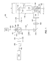
- FIG. 1 presents a schematic diagram of parts comprising the dual beam optical interferometer of the present invention, in one embodiment.
- FIG. 2 is a schematic representation of a target surface, such as the upper surface of a magnetic disc. Two beams as generated in the diagram of FIG. 1 are seen striking the target surface in offset fashion.
- FIG. 1 presents a diagram of a dual-beam, common path optical interferometer 100 of the present invention, in one embodiment.
- two beams 110 and 120 are generated through the interferometer 100 .
- the beams 110 , 120 are directed towards a target surface 150 under analysis.
- the target surface 150 is a mirror-like, highly reflective, ultra-smooth disc surface, such as the surface of a magnetic data storage disc.
- the present invention has utility in measuring smoothness of other smooth surfaces, such as silicon dioxide wafers.
- a light source 200 is first provided.
- the light source 200 defines a He—Ne laser.
- the laser 200 supplies a single, polarized laser beam 105 , in which the beam 105 is continuous.
- the beam 105 may be in either the P-polarization state or the S-polarization state, depending upon the configuration of other components as will be shown.
- the polarized beam 105 is transmitted through an optical isolator 250 .
- the optical isolator 250 serves to direct the light beam 105 , and prevents the light beam 105 from returning to the laser 200 during the disc testing process.
- An example of a suitable optical isolator is product no. 501010 manufactured by Linos Photonics.
- the polarized beam 105 is transmitted through the optical isolator 250 , it is directed to a first beam splitter 240 .
- the beam splitter 240 is an intensity beam splitter.
- the beam splitter 240 divides the single beam 105 into two parts of substantially equal intensity.
- the two beams are designated as beam one 110 and beam two 120 .
- Beam one 110 and beam two 120 each remain in their original state of polarization at this point.
- the polarization state is the P-polarization state.
- Each beam 110 , 120 is transmitted to a mirror.
- Beam one 110 is transmitted through the beam splitter 240 to mirror one 112 , while beam two 120 is redirected at 90 degrees by the first beam splitter 240 to mirror two 212 .
- mirror one 112 reflects beam one 110 at 45 degrees.
- mirror two 212 reflects beam two 120 at 45 degrees. The result is that each beam 110 , 120 is redirected at 90 degrees towards the same location, i.e., a polarizing cube beam splitter 160 .
- beam one 110 passes through a long working distance objective (“LWO one”) 114 .
- LWO one 114 serves to focus beam one 110 onto a target surface 150 .
- Beam one 110 passes through the polarizing cube beam splitter 160 before hitting the target surface 150 . Because the beam 110 is in its P-polarization state, it is transmitted essentially straight through the cube beam splitter 160 and onto the target surface 150 .
- beam two 120 moves from mirror two 212 and also moves towards a long working distance objective.
- the long working distance objective is “LWO two” 124 .
- beam two 120 passes through a half-wave plate (“HWP”) 126 before it is focused onto the target surface 150 by LWO two 124 .
- the HWP 126 is aligned so that the transmitted beam 120 ′ consists primarily of S-polarized light.
- the light 120 ′ received and focused by the long working distance objective two 124 is in the S-polarization state.
- the S-polarized beam 120 ′ is received by the cube beam splitter 160 .
- the S-polarized beam 120 ′ is not transmitted through the cube beam splitter 160 , but is reflected onto the target surface 150 at a designated angle. In the arrangement shown in FIG. 1 , the reflection angle is 45 degrees.
- the objective LWO one 114 and mirror one 112 are built together as a block assembly.
- the block assembly is shown schematically in phantom at 118 .
- the assembly 118 is connected to a piezoelectric translator (not shown).
- the piezoelectric translator provides movement of the block 118 parallel to beam one 110 with an accuracy and resolution of less than 1 nanometer resolution. Bilateral movement of the block 118 is shown by arrow “a.” This allows the apparatus 100 to accurately control and adjust the separation distance “d” between beam one 110 and beam two 120 as the beams 110 , 120 strike the target surface 150 .
- FIG. 2 is a schematic representation of a target surface 150 , such as the upper surface of a magnetic disc.
- Two beams 110 , 120 ′ as generated in the diagram of FIG. 1 are seen striking the target surface 150 in offset fashion. Beam one 110 and beam two 120 ′ reflect off the target surface 150 . The reflected beams are shown as 210 and 220 , respectively.
- FIG. 2 is an enlarged view of a portion of FIG. 1 .
- the target surface 150 appears planar.
- a surface irregularity is visible.
- a magnetic disc surface is not always perfectly planar, but may have topographical variations.
- a topographical variation is demonstrated by local amplitude “dH.”
- a magnetic disc having a significant surface amplitude dH within a short wavelength is considered defective.
- each beam 110 , 120 ′ is reflected back towards the polarizing cube beam splitter 160 .
- the beams 210 , 220 reflect back from the focal points along their respective original paths.
- reflected beam one 210 returns through the LWO one 114 , against mirror one 112 , and back to the original beam splitter 240 .
- Reflected beam two 220 reflects against the polarizing cube beam splitter 160 , passes through the LWO two 214 , reflects again against mirror two 212 , and returns to the intensity beam splitter 240 .
- Beam two 220 returns to its original polarization state after transmitting through half wave plate 126 .
- the beams 210 and 220 can interfere with each other once they recombine again at beam splitter 240 .
- the two reflected beams 210 , 220 are each split at the original beam splitter 240 .
- the reflected first beam 210 splits into beams 410 and 411 Beam 410 travels back towards optical isolator 250 , while beam 411 reflects to a photodiode 300 .
- the second reflected beam 220 also splits into two beams, to wit, beams 420 and 421 . Beam 420 is reflected towards the optical isolator 250 , while beam 421 travels on to the photodiode 300 .
- Each beam 410 , 411 and 420 , 421 is comprised in approximately 50/50 ratios of the reflected first 210 and second 220 beams.
- a new recombined first beam 310 is thus formed by beams 410 and 420
- a new recombined second beam 320 is thus formed by beams 411 and 421 at the intensity beam splitter 240 .
- the newly constituted first beam 310 travels towards to the laser 200 . However, the new first beam 310 is blocked by the optical isolator 250 before it returns into the laser 200 .
- the newly constituted second beam 320 travels towards the photodiode 300 .
- This new second beam 320 received at the photodiode 300 produces interference fringes as a result of the modulation of the optical path length difference between the two beams 210 , 220 .
- the photodiode 300 captures these moving or changing fringes, which are observed as temporal variations in light intensity.
- the photodiode 300 then delivers a voltage signal proportional to the temporal light intensity change.
- This voltage signal “s,” in turn, can be analyzed by subsequent digital signal processing as is known in the art.
- I 1 and I 2 are the intensities of beam 411 and beam two 421 , respectively
- ⁇ is the phase difference between the two beams 411 (or 210 ), 421 (or 220 ).
- ⁇ is the wavelength of the laser light.
- ⁇ L 2( d+dH ) (3)
- the first term in the equation (4) is a constant because the beam separation d is pre-determined based on the minimum spatial wavelength required to be detected. Therefore, the phase angle ⁇ is a function of dH, which is itself a function of the local surface slope.
- df/dx slope, or df/dx ⁇ dS.
- dx is d, the separation of beam one 110 and beam two 120 ′.
- the profile or topography of the surface 150 can then be calculated by integration of the slope information.
- equation (1) there are two other unknowns, to wit, I 1 and I 2 , that must be resolved before equation (1) can be solved. These two unknowns can be obtained by using I max and I min techniques.
- the I max and I min techniques are described in J. Wang and I Grant, “ ESPI, Phase Mapping, NDT The Techniques Applied to Real - Time, Thermal Loading, ” Applied Optics 34, 3620–3627 (1995).
- the approach for obtaining I max and I min can be determined by moving the block assembly 118 backward and forward with the piezoelectric translator in order to vary the optical path length difference between the two beams, ⁇ L, such that a full cycle or more of moving interference fringes are generated. As long as the moving distance is greater than laser light wavelength, a full cycle moving fringe will be generated. The intensities of the moving fringes can be detected by the photodiode 300 . From there, the I max and I min can then be obtained. We can then re-write Equation (1) as:
- I I a +I b ⁇ cos( ⁇ ) (6)
- the profiling dynamic range is determined by the local height difference, dH, which is caused by the slope of the surface topography.
- the maximum dH which can be observed without causing a phase unwrapping problem is given by the second term of Equation (2) when it is set equal to ⁇ .
- ⁇ 4 ⁇ ⁇ ⁇ ⁇ ⁇ ⁇ dH ⁇ ⁇ ⁇ or ( 7 )
- dH ⁇ 4 ( 8 )
- a He—Ne laser has a known wavelength of 0.6328 ⁇ m.
- the maximum dH is 0.133 ⁇ m. This range is much greater than the maximum local slope on an ultra-smooth surface, such as a hard disc surface.
- a typical hard disc whose surface topography in the circumferential direction can be depicted by a sinusoidal function with 5 ⁇ m amplitude, or 10 ⁇ m peak-to-peak in amplitude, has a maximum dH of 0.004 ⁇ m for a radius of 25.4 mm and a sampling interval d of 10 ⁇ m. Therefore, this interferometer does not require phase unwrapping for most applications involving smooth surfaces. This increases the accuracy of the measurement and reduces the data processing time.
- the dual beam interferometer of the present invention may be made with various applications. Because the body movement between the profiling interferometer 100 and the testing object 150 will have little or no effect on the surface topography measurement, this type profiler 100 is well-suited to portable applications.
- the profiler 100 could be used for measuring HMS_Wq of the disc 150 on all kind of spindles, include measuring the discs in assembled hard disk drives.
- the profiler 100 may also be used for measuring disc edge roll-off without the need for an ultra-flat motion stage.
- the light source 200 may generate a continuous light beam 105 that is in the S-polarization state rather than the P-polarization state.
- the half wave plate 126 would be in the path of beam one 110 rather than in the path of beam two 120 .
Abstract
Description
I=I 1 +I 2+2√{square root over (I 1 ·I 2)}·cos(φ) (1)
where, I1 and I2 are the intensities of
ΔL=2(d+dH) (3)
dS=dHId (5)
I=I a +I b·cos(φ) (6)
Claims (24)
Priority Applications (1)
| Application Number | Priority Date | Filing Date | Title |
|---|---|---|---|
| US10/690,447 US7019840B2 (en) | 2003-06-17 | 2003-10-21 | Dual-beam interferometer for ultra-smooth surface topographical measurements |
Applications Claiming Priority (2)
| Application Number | Priority Date | Filing Date | Title |
|---|---|---|---|
| US47929403P | 2003-06-17 | 2003-06-17 | |
| US10/690,447 US7019840B2 (en) | 2003-06-17 | 2003-10-21 | Dual-beam interferometer for ultra-smooth surface topographical measurements |
Publications (2)
| Publication Number | Publication Date |
|---|---|
| US20040257582A1 US20040257582A1 (en) | 2004-12-23 |
| US7019840B2 true US7019840B2 (en) | 2006-03-28 |
Family
ID=33519349
Family Applications (1)
| Application Number | Title | Priority Date | Filing Date |
|---|---|---|---|
| US10/690,447 Expired - Fee Related US7019840B2 (en) | 2003-06-17 | 2003-10-21 | Dual-beam interferometer for ultra-smooth surface topographical measurements |
Country Status (1)
| Country | Link |
|---|---|
| US (1) | US7019840B2 (en) |
Cited By (8)
| Publication number | Priority date | Publication date | Assignee | Title |
|---|---|---|---|---|
| FR2674958A1 (en) * | 1991-04-03 | 1992-10-09 | Saplest Production | Method and installation for non destructive measurement of the density of a cellular (honeycombed) polymer article |
| US20050179879A1 (en) * | 2003-10-30 | 2005-08-18 | Asml Netherlands B.V. | Lithographic apparatus, interferometer and device manufacturing method |
| US20070229815A1 (en) * | 2004-06-02 | 2007-10-04 | Komatsu Electronic Metals Co., Ltd. | Apparatus and Method for Inspecting Semiconductor Wafer |
| TWI472715B (en) * | 2013-07-18 | 2015-02-11 | Univ Nan Kai Technology | An interferometric configuration based of synchronous measurement of dynamic surface profile |
| CN104858547A (en) * | 2015-04-17 | 2015-08-26 | 温州职业技术学院 | Laser processing head based on double-beam spatial characteristic adjustment |
| CN109935244A (en) * | 2019-03-26 | 2019-06-25 | 北京清正泰科技术有限公司 | A kind of contact hard disc magnetic head and preparation method thereof |
| CN109949832A (en) * | 2019-03-26 | 2019-06-28 | 北京清正泰科技术有限公司 | A kind of contact head sliding block formed based on superslide structure |
| CN110779448A (en) * | 2019-09-19 | 2020-02-11 | 中北大学 | Double-interference type high-frame-frequency sampling micro-displacement measurement method based on vortex rotation |
Families Citing this family (2)
| Publication number | Priority date | Publication date | Assignee | Title |
|---|---|---|---|---|
| DE102007054734B4 (en) * | 2007-11-16 | 2009-12-24 | GFE Gesellschaft für Fertigungstechnik u. Entwicklung Schmalkalden e.V. | Method for detecting a surface profile |
| JP2015011747A (en) * | 2013-06-28 | 2015-01-19 | 株式会社東芝 | Disc storage device, and management method of storage region |
Citations (18)
| Publication number | Priority date | Publication date | Assignee | Title |
|---|---|---|---|---|
| US4128337A (en) | 1977-06-13 | 1978-12-05 | Visidyne, Inc. | Method of and apparatus for interferometric background suppression |
| US4833314A (en) | 1987-02-13 | 1989-05-23 | Hughes Aircraft Company | Variable phase stop for use in interferometers |
| US5469259A (en) * | 1994-01-03 | 1995-11-21 | International Business Machines Corporation | Inspection interferometer with scanning autofocus, and phase angle control features |
| US5574560A (en) | 1994-02-26 | 1996-11-12 | Dr. Johannes Heidenhain Gmbh | Dual-beam interferometer with a phase grating |
| US5671050A (en) | 1994-11-07 | 1997-09-23 | Zygo Corporation | Method and apparatus for profiling surfaces using diffracative optics |
| US5699160A (en) * | 1996-09-23 | 1997-12-16 | International Business Machines Corporation | Optical apparatus for inspecting laser texture |
| US5703684A (en) * | 1996-09-23 | 1997-12-30 | International Business Machines Corporation | Apparatus for optical differential measurement of glide height above a magnetic disk |
| US5710631A (en) * | 1995-04-11 | 1998-01-20 | International Business Machines Corporation | Apparatus and method for storing interferometric images of scanned defects and for subsequent static analysis of such defects |
| US5737079A (en) | 1994-11-07 | 1998-04-07 | Rayleigh Optical Corporation | System and method for interferometric measurement of aspheric surfaces utilizing test plate provided with computer-generated hologram |
| US5784163A (en) * | 1996-09-23 | 1998-07-21 | International Business Machines Corporation | Optical differential profile measurement apparatus and process |
| US5838441A (en) | 1997-07-23 | 1998-11-17 | The United States Of America As Represented By The National Security Agency | Wide field of view coherent light detector and locator |
| US5877856A (en) * | 1996-05-14 | 1999-03-02 | Carl Zeiss Jena Gmbh | Methods and arrangement for increasing contrast in optical coherence tomography by means of scanning an object with a dual beam |
| US5999261A (en) | 1998-02-10 | 1999-12-07 | Seagate Technology, Inc. | Split phase high performance, high frequency, high dynamic range interferometer |
| US6034924A (en) | 1998-04-03 | 2000-03-07 | The Board Of Trustees Of The Leland Stanford Junior Univerisity | Folded sagnac sensor array |
| US6097486A (en) | 1998-04-03 | 2000-08-01 | The Board Of Trustees Of The Leland Stanford Junior University | Fiber optic acoustic sensor array based on Sagnac interferometer |
| US6278657B1 (en) | 1998-04-03 | 2001-08-21 | The Board Of Trustees Of The Leland Stanford Junior University | Folded sagnac sensor array |
| US6657216B1 (en) * | 2002-06-17 | 2003-12-02 | Nanometrics Incorporated | Dual spot confocal displacement sensor |
| US6690473B1 (en) * | 1999-02-01 | 2004-02-10 | Sensys Instruments Corporation | Integrated surface metrology |
Family Cites Families (1)
| Publication number | Priority date | Publication date | Assignee | Title |
|---|---|---|---|---|
| US5535441A (en) * | 1994-09-30 | 1996-07-09 | Hughes Electronics Corp. | Method and device for canceling frequency offsets |
-
2003
- 2003-10-21 US US10/690,447 patent/US7019840B2/en not_active Expired - Fee Related
Patent Citations (19)
| Publication number | Priority date | Publication date | Assignee | Title |
|---|---|---|---|---|
| US4128337A (en) | 1977-06-13 | 1978-12-05 | Visidyne, Inc. | Method of and apparatus for interferometric background suppression |
| US4833314A (en) | 1987-02-13 | 1989-05-23 | Hughes Aircraft Company | Variable phase stop for use in interferometers |
| US5469259A (en) * | 1994-01-03 | 1995-11-21 | International Business Machines Corporation | Inspection interferometer with scanning autofocus, and phase angle control features |
| US5574560A (en) | 1994-02-26 | 1996-11-12 | Dr. Johannes Heidenhain Gmbh | Dual-beam interferometer with a phase grating |
| US5737079A (en) | 1994-11-07 | 1998-04-07 | Rayleigh Optical Corporation | System and method for interferometric measurement of aspheric surfaces utilizing test plate provided with computer-generated hologram |
| US5671050A (en) | 1994-11-07 | 1997-09-23 | Zygo Corporation | Method and apparatus for profiling surfaces using diffracative optics |
| US5710631A (en) * | 1995-04-11 | 1998-01-20 | International Business Machines Corporation | Apparatus and method for storing interferometric images of scanned defects and for subsequent static analysis of such defects |
| US5877856A (en) * | 1996-05-14 | 1999-03-02 | Carl Zeiss Jena Gmbh | Methods and arrangement for increasing contrast in optical coherence tomography by means of scanning an object with a dual beam |
| US5703684A (en) * | 1996-09-23 | 1997-12-30 | International Business Machines Corporation | Apparatus for optical differential measurement of glide height above a magnetic disk |
| US5784163A (en) * | 1996-09-23 | 1998-07-21 | International Business Machines Corporation | Optical differential profile measurement apparatus and process |
| US5699160A (en) * | 1996-09-23 | 1997-12-16 | International Business Machines Corporation | Optical apparatus for inspecting laser texture |
| US5838441A (en) | 1997-07-23 | 1998-11-17 | The United States Of America As Represented By The National Security Agency | Wide field of view coherent light detector and locator |
| US5999261A (en) | 1998-02-10 | 1999-12-07 | Seagate Technology, Inc. | Split phase high performance, high frequency, high dynamic range interferometer |
| US6034924A (en) | 1998-04-03 | 2000-03-07 | The Board Of Trustees Of The Leland Stanford Junior Univerisity | Folded sagnac sensor array |
| US6097486A (en) | 1998-04-03 | 2000-08-01 | The Board Of Trustees Of The Leland Stanford Junior University | Fiber optic acoustic sensor array based on Sagnac interferometer |
| US6278657B1 (en) | 1998-04-03 | 2001-08-21 | The Board Of Trustees Of The Leland Stanford Junior University | Folded sagnac sensor array |
| US6529444B2 (en) | 1998-04-03 | 2003-03-04 | The Board Of Trustees Of The Leland Stanford Junior University | Folded sagnac sensor array |
| US6690473B1 (en) * | 1999-02-01 | 2004-02-10 | Sensys Instruments Corporation | Integrated surface metrology |
| US6657216B1 (en) * | 2002-06-17 | 2003-12-02 | Nanometrics Incorporated | Dual spot confocal displacement sensor |
Non-Patent Citations (7)
| Title |
|---|
| G.E. Sommargren, "Optical heterodyne profilometry," App. Opt., 20, (4) 610-618, 1981. |
| J.M. Zavislan and J.M. Eastman, "Microprofiling of precision surfaces," in Measurement and effects of surface defects and Quality of Polish, Proc. SPIE, 525, 169-173, 1985. |
| Jianmin Wang and Ian Grant, "ESPI, Phase mapping, NDT the techniques applied to real-time, thermal loading," Appl. Opt. 34, 3620-3627, (1995). |
| Jianmin Wang and Jason Pressesky, "Quadrature Phase Shift Interferometer (QPSI) Decoding Algorithm," Seagate disclosure, STL 3304, 2003. |
| M.J. Downs, N.M. Mason and J.C. Nelson, "Measurement of the profiles of 'super-smooth' surface using optical interferometry," in Surface Measurement and Charachterization, Proc. SPIE, 1009, 14-17, 1988. |
| Shih-Fu Lee, Young Hu and David S. Kuo, "Monitoring magnetic disk waviness using head AAB tranfer function and HMS modulation," Seagate disclosure, STL 3025, 2001. |
| T.C. Bristow and D. Lindquist, "Surface measurements with a non-contact Normarski-profiling instrument," in Interfermetric Metrology, Proc. SPIE, 816, 106-110, 1987. |
Cited By (11)
| Publication number | Priority date | Publication date | Assignee | Title |
|---|---|---|---|---|
| FR2674958A1 (en) * | 1991-04-03 | 1992-10-09 | Saplest Production | Method and installation for non destructive measurement of the density of a cellular (honeycombed) polymer article |
| US20050179879A1 (en) * | 2003-10-30 | 2005-08-18 | Asml Netherlands B.V. | Lithographic apparatus, interferometer and device manufacturing method |
| US7251042B2 (en) * | 2003-10-30 | 2007-07-31 | Asml Netherlands B.V. | Lithographic apparatus, interferometer and device manufacturing method |
| US20070229815A1 (en) * | 2004-06-02 | 2007-10-04 | Komatsu Electronic Metals Co., Ltd. | Apparatus and Method for Inspecting Semiconductor Wafer |
| US7522290B2 (en) * | 2004-06-02 | 2009-04-21 | Sumco Tech Xiv Corporation | Apparatus and method for inspecting semiconductor wafer |
| TWI472715B (en) * | 2013-07-18 | 2015-02-11 | Univ Nan Kai Technology | An interferometric configuration based of synchronous measurement of dynamic surface profile |
| CN104858547A (en) * | 2015-04-17 | 2015-08-26 | 温州职业技术学院 | Laser processing head based on double-beam spatial characteristic adjustment |
| CN109935244A (en) * | 2019-03-26 | 2019-06-25 | 北京清正泰科技术有限公司 | A kind of contact hard disc magnetic head and preparation method thereof |
| CN109949832A (en) * | 2019-03-26 | 2019-06-28 | 北京清正泰科技术有限公司 | A kind of contact head sliding block formed based on superslide structure |
| CN110779448A (en) * | 2019-09-19 | 2020-02-11 | 中北大学 | Double-interference type high-frame-frequency sampling micro-displacement measurement method based on vortex rotation |
| CN110779448B (en) * | 2019-09-19 | 2021-10-26 | 中北大学 | Double-interference type high-frame-frequency sampling micro-displacement measurement method based on vortex rotation |
Also Published As
| Publication number | Publication date |
|---|---|
| US20040257582A1 (en) | 2004-12-23 |
Similar Documents
| Publication | Publication Date | Title |
|---|---|---|
| US6271924B1 (en) | Noncontact acoustic optic scanning laser vibrometer for determining the difference between an object and a reference surface | |
| US4844616A (en) | Interferometric dimensional measurement and defect detection method | |
| US5349440A (en) | Interferometric laser profilometer including a multimode laser diode emitting a range of stable wavelengths | |
| US7405830B2 (en) | Vibration-insensitive interferometer | |
| US20060262291A1 (en) | Dynamic reference plane compensation | |
| US7019840B2 (en) | Dual-beam interferometer for ultra-smooth surface topographical measurements | |
| US4498771A (en) | Method and means for interferometric surface topography | |
| JPH03504647A (en) | single beam ac interferometer | |
| US5481360A (en) | Optical device for measuring surface shape | |
| JP2008516369A (en) | Approach between optical lens and carrier in near field | |
| US5600441A (en) | Interferometer and method for measuring the distance of an object surface with respect to the surface of a rotating disk | |
| JPH0455243B2 (en) | ||
| US6710881B1 (en) | Heterodyne interferometry for small spacing measurement | |
| US6259530B1 (en) | Method and device for measuring the depths of bottoms of craters in a physico-chemical analyzer | |
| KR100503007B1 (en) | Apparatus for detecting sub-resonance of actuator for optical pickup | |
| JPH0256604B2 (en) | ||
| JP4843789B2 (en) | Nanometer displacement measuring method and apparatus by laser speckle | |
| US20100128282A1 (en) | Phase difference comparison to measure very small spacing between bodies | |
| US7916308B2 (en) | Method and optical profiler | |
| JP4536873B2 (en) | Three-dimensional shape measuring method and apparatus | |
| JP3325078B2 (en) | Non-contact three-dimensional shape measuring device | |
| JP2541197Y2 (en) | Interference shape measuring instrument | |
| JP3139862B2 (en) | Surface defect inspection equipment | |
| JP3217543B2 (en) | Hard disk head flying height measurement device | |
| Clegg et al. | Normal incidence polarization interferometry flying height testing |
Legal Events
| Date | Code | Title | Description |
|---|---|---|---|
| AS | Assignment |
Owner name: SEAGATE TECHNOLOGY LLC, CALIFORNIA Free format text: ASSIGNMENT OF ASSIGNORS INTEREST;ASSIGNORS:WANG, JIANMIN;PRESSESKY, JASON;WANG, LI-PING;REEL/FRAME:014622/0433 Effective date: 20031007 |
|
| AS | Assignment |
Owner name: JPMORGAN CHASE BANK, N.A., AS ADMINISTRATIVE AGENT Free format text: SECURITY AGREEMENT;ASSIGNORS:MAXTOR CORPORATION;SEAGATE TECHNOLOGY LLC;SEAGATE TECHNOLOGY INTERNATIONAL;REEL/FRAME:022757/0017 Effective date: 20090507 Owner name: WELLS FARGO BANK, NATIONAL ASSOCIATION, AS COLLATE Free format text: SECURITY AGREEMENT;ASSIGNORS:MAXTOR CORPORATION;SEAGATE TECHNOLOGY LLC;SEAGATE TECHNOLOGY INTERNATIONAL;REEL/FRAME:022757/0017 Effective date: 20090507 |
|
| FPAY | Fee payment |
Year of fee payment: 4 |
|
| FEPP | Fee payment procedure |
Free format text: PAYOR NUMBER ASSIGNED (ORIGINAL EVENT CODE: ASPN); ENTITY STATUS OF PATENT OWNER: LARGE ENTITY Free format text: PAYER NUMBER DE-ASSIGNED (ORIGINAL EVENT CODE: RMPN); ENTITY STATUS OF PATENT OWNER: LARGE ENTITY |
|
| AS | Assignment |
Owner name: SEAGATE TECHNOLOGY INTERNATIONAL, CALIFORNIA Free format text: RELEASE;ASSIGNOR:JPMORGAN CHASE BANK, N.A., AS ADMINISTRATIVE AGENT;REEL/FRAME:025662/0001 Effective date: 20110114 Owner name: SEAGATE TECHNOLOGY HDD HOLDINGS, CALIFORNIA Free format text: RELEASE;ASSIGNOR:JPMORGAN CHASE BANK, N.A., AS ADMINISTRATIVE AGENT;REEL/FRAME:025662/0001 Effective date: 20110114 Owner name: SEAGATE TECHNOLOGY LLC, CALIFORNIA Free format text: RELEASE;ASSIGNOR:JPMORGAN CHASE BANK, N.A., AS ADMINISTRATIVE AGENT;REEL/FRAME:025662/0001 Effective date: 20110114 Owner name: MAXTOR CORPORATION, CALIFORNIA Free format text: RELEASE;ASSIGNOR:JPMORGAN CHASE BANK, N.A., AS ADMINISTRATIVE AGENT;REEL/FRAME:025662/0001 Effective date: 20110114 |
|
| AS | Assignment |
Owner name: THE BANK OF NOVA SCOTIA, AS ADMINISTRATIVE AGENT, Free format text: SECURITY AGREEMENT;ASSIGNOR:SEAGATE TECHNOLOGY LLC;REEL/FRAME:026010/0350 Effective date: 20110118 |
|
| AS | Assignment |
Owner name: EVAULT INC. (F/K/A I365 INC.), CALIFORNIA Free format text: TERMINATION AND RELEASE OF SECURITY INTEREST IN PATENT RIGHTS;ASSIGNOR:WELLS FARGO BANK, NATIONAL ASSOCIATION, AS COLLATERAL AGENT AND SECOND PRIORITY REPRESENTATIVE;REEL/FRAME:030833/0001 Effective date: 20130312 Owner name: SEAGATE TECHNOLOGY LLC, CALIFORNIA Free format text: TERMINATION AND RELEASE OF SECURITY INTEREST IN PATENT RIGHTS;ASSIGNOR:WELLS FARGO BANK, NATIONAL ASSOCIATION, AS COLLATERAL AGENT AND SECOND PRIORITY REPRESENTATIVE;REEL/FRAME:030833/0001 Effective date: 20130312 Owner name: SEAGATE TECHNOLOGY INTERNATIONAL, CAYMAN ISLANDS Free format text: TERMINATION AND RELEASE OF SECURITY INTEREST IN PATENT RIGHTS;ASSIGNOR:WELLS FARGO BANK, NATIONAL ASSOCIATION, AS COLLATERAL AGENT AND SECOND PRIORITY REPRESENTATIVE;REEL/FRAME:030833/0001 Effective date: 20130312 Owner name: SEAGATE TECHNOLOGY US HOLDINGS, INC., CALIFORNIA Free format text: TERMINATION AND RELEASE OF SECURITY INTEREST IN PATENT RIGHTS;ASSIGNOR:WELLS FARGO BANK, NATIONAL ASSOCIATION, AS COLLATERAL AGENT AND SECOND PRIORITY REPRESENTATIVE;REEL/FRAME:030833/0001 Effective date: 20130312 |
|
| FPAY | Fee payment |
Year of fee payment: 8 |
|
| FEPP | Fee payment procedure |
Free format text: MAINTENANCE FEE REMINDER MAILED (ORIGINAL EVENT CODE: REM.) |
|
| LAPS | Lapse for failure to pay maintenance fees |
Free format text: PATENT EXPIRED FOR FAILURE TO PAY MAINTENANCE FEES (ORIGINAL EVENT CODE: EXP.) |
|
| STCH | Information on status: patent discontinuation |
Free format text: PATENT EXPIRED DUE TO NONPAYMENT OF MAINTENANCE FEES UNDER 37 CFR 1.362 |
|
| FP | Lapsed due to failure to pay maintenance fee |
Effective date: 20180328 |