US7011141B2 - Apparatus and method for producing single crystal metallic objects - Google Patents
Apparatus and method for producing single crystal metallic objects Download PDFInfo
- Publication number
- US7011141B2 US7011141B2 US10/652,906 US65290603A US7011141B2 US 7011141 B2 US7011141 B2 US 7011141B2 US 65290603 A US65290603 A US 65290603A US 7011141 B2 US7011141 B2 US 7011141B2
- Authority
- US
- United States
- Prior art keywords
- mold
- notch
- sorter
- passage
- single crystal
- Prior art date
- Legal status (The legal status is an assumption and is not a legal conclusion. Google has not performed a legal analysis and makes no representation as to the accuracy of the status listed.)
- Expired - Lifetime, expires
Links
- 239000013078 crystal Substances 0.000 title claims abstract description 21
- 238000004519 manufacturing process Methods 0.000 title description 5
- 238000005266 casting Methods 0.000 claims abstract description 20
- 229910052751 metal Inorganic materials 0.000 claims abstract description 15
- 239000002184 metal Substances 0.000 claims abstract description 15
- 230000008646 thermal stress Effects 0.000 claims abstract description 14
- 238000004891 communication Methods 0.000 claims abstract description 10
- 239000012530 fluid Substances 0.000 claims abstract description 10
- 238000000034 method Methods 0.000 claims description 19
- 238000007711 solidification Methods 0.000 claims description 12
- 230000008023 solidification Effects 0.000 claims description 12
- 238000003776 cleavage reaction Methods 0.000 claims description 4
- 230000007017 scission Effects 0.000 claims description 4
- 230000007547 defect Effects 0.000 abstract 1
- 230000008569 process Effects 0.000 description 11
- 238000013461 design Methods 0.000 description 8
- 238000002474 experimental method Methods 0.000 description 8
- 230000035882 stress Effects 0.000 description 6
- 230000000694 effects Effects 0.000 description 5
- 230000002787 reinforcement Effects 0.000 description 5
- PNEYBMLMFCGWSK-UHFFFAOYSA-N aluminium oxide Inorganic materials [O-2].[O-2].[O-2].[Al+3].[Al+3] PNEYBMLMFCGWSK-UHFFFAOYSA-N 0.000 description 4
- 239000000919 ceramic Substances 0.000 description 4
- OKTJSMMVPCPJKN-UHFFFAOYSA-N Carbon Chemical compound [C] OKTJSMMVPCPJKN-UHFFFAOYSA-N 0.000 description 3
- 238000013459 approach Methods 0.000 description 3
- 239000004568 cement Substances 0.000 description 3
- 229910002804 graphite Inorganic materials 0.000 description 3
- 239000010439 graphite Substances 0.000 description 3
- 238000012986 modification Methods 0.000 description 3
- 230000004048 modification Effects 0.000 description 3
- 229910052782 aluminium Inorganic materials 0.000 description 2
- XAGFODPZIPBFFR-UHFFFAOYSA-N aluminium Chemical compound [Al] XAGFODPZIPBFFR-UHFFFAOYSA-N 0.000 description 2
- 239000003795 chemical substances by application Substances 0.000 description 2
- 239000004744 fabric Substances 0.000 description 2
- 239000000835 fiber Substances 0.000 description 2
- 239000000463 material Substances 0.000 description 2
- 230000002028 premature Effects 0.000 description 2
- 230000002411 adverse Effects 0.000 description 1
- 239000000956 alloy Substances 0.000 description 1
- 229910045601 alloy Inorganic materials 0.000 description 1
- 230000015572 biosynthetic process Effects 0.000 description 1
- 229910010293 ceramic material Inorganic materials 0.000 description 1
- 238000006243 chemical reaction Methods 0.000 description 1
- 238000005336 cracking Methods 0.000 description 1
- 230000007812 deficiency Effects 0.000 description 1
- 238000007598 dipping method Methods 0.000 description 1
- 230000005611 electricity Effects 0.000 description 1
- 230000002708 enhancing effect Effects 0.000 description 1
- 230000003993 interaction Effects 0.000 description 1
- 239000007788 liquid Substances 0.000 description 1
- 238000005058 metal casting Methods 0.000 description 1
- 230000006911 nucleation Effects 0.000 description 1
- 238000010899 nucleation Methods 0.000 description 1
- 230000008520 organization Effects 0.000 description 1
- 230000037361 pathway Effects 0.000 description 1
- 239000000843 powder Substances 0.000 description 1
- 230000002035 prolonged effect Effects 0.000 description 1
- 230000001902 propagating effect Effects 0.000 description 1
- 239000002002 slurry Substances 0.000 description 1
- 238000012360 testing method Methods 0.000 description 1
Images

Classifications
-
- C—CHEMISTRY; METALLURGY
- C30—CRYSTAL GROWTH
- C30B—SINGLE-CRYSTAL GROWTH; UNIDIRECTIONAL SOLIDIFICATION OF EUTECTIC MATERIAL OR UNIDIRECTIONAL DEMIXING OF EUTECTOID MATERIAL; REFINING BY ZONE-MELTING OF MATERIAL; PRODUCTION OF A HOMOGENEOUS POLYCRYSTALLINE MATERIAL WITH DEFINED STRUCTURE; SINGLE CRYSTALS OR HOMOGENEOUS POLYCRYSTALLINE MATERIAL WITH DEFINED STRUCTURE; AFTER-TREATMENT OF SINGLE CRYSTALS OR A HOMOGENEOUS POLYCRYSTALLINE MATERIAL WITH DEFINED STRUCTURE; APPARATUS THEREFOR
- C30B11/00—Single-crystal growth by normal freezing or freezing under temperature gradient, e.g. Bridgman-Stockbarger method
- C30B11/002—Crucibles or containers for supporting the melt
Definitions
- the present invention relates generally to the field of process of forming metallic objects through directional solidification and more particularly to an optimized mold design for use in such process.
- the process of directional solidification is well known in the production and manufacture of turbine elements such as rotor blades, stator vanes as well as other airfoil components having a single crystal structure.
- the process involves providing a seed cavity at the base of the mold, wherein the restrictive shape of the pathway from the seed cavity to the part-defining cavity (sometimes referred to as the sorter or selector) encourages the formation of a single crystal structure during solidification of a molten alloy.
- the mold is then withdrawn from a heated environment or otherwise linearly cooled such that the propagating single crystal structure proceeds up the length of the part, thereby resulting in the entire part having this structure.
- Examples of conventional directional solidification processes may be found in U.S. Pat. Nos. 3,494,709, 4,940,073 and 5,062,469.
- Suitable molds for use in such directional solidification processes traditionally include ceramic molds formed using the investment or “lost wax method” wherein a wax pattern having the desired shape of the mold is first formed. The wax pattern is then covered with a layer of ceramic material, from which the wax is then removed, thereby leaving a ceramic mold of the desired shape.
- a mold for enabling casting of single crystal metallic articles including a part-defining cavity, a sorter passage positioned vertically beneath and in fluid communication with the part-defining cavity, and a seed cavity positioned vertically beneath and in fluid communication with the sorter passage.
- the sorter passage includes a shape suitable for encouraging a single crystal structure in solidifying molten metal.
- a portion of the mold between the sorter passage and the part-defining cavity includes a notch for facilitating breakage of a cast article proximate the notch during thermal stress build-up.
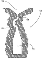
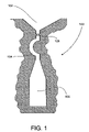
- FIG. 1 is a sectional view of a portion of a mold constructed in accordance with one embodiment of the present invention.
- FIGS. 2 and 3 are exploded sectional views of alternate embodiments of a notch positioned in a portion of a mold between a sorter passage and a part-defining cavity.
- FIG. 1 there is shown a sectional view of a portion of a mold 100 constructed in accordance with one embodiment of the present invention.
- the mold 100 includes a part-defining cavity 102 (the majority of which is not shown). Molten metal flows downwardly through the part-defining cavity 102 and through a sorter passage 104 and into a seed cavity 106 .
- the cross-section of the sorter passage 104 is generally cylindrical, although alternate shapes may be utilized without departing from the scope of the present invention.
- the mold Upon filling with molten metal, the mold is directionally cooled, starting with the seed cavity 106 . As it cools, the metal solidifies in the seed cavity 106 as a plurality of elongated grains which extend upwardly toward the sorter passage 104 .
- the geometry of the sorter passage 104 and the part-defining cavity 102 is such that it acts as a locking point to build up a large thermal stresses above it. If left unmanaged, the thermal stress can cause mold breakage. According to a first embodiment of the present invention, such adverse effects are reduced by constructing the portion of the mold between the sorter passage 104 and the part-defining cavity 102 to include a notch 108 . The presence of notch 108 provides a stress release point in the resultant metal casting, such that the mold can remain intact without breakage.
- notch 108 should be sufficiently small so as to result in breakage of the casting from the thermal stresses before such stresses can damage the mold. Conversely, the notch 108 cannot be too severe so as to restrict the flow of molten metal through the sorter passage and into the seed cavity. Additionally, a severe notch may also make the assembly and handling of the wax pattern used to form the mold more difficult.
- the diameter of the circumferentially notched portion should be greater than or equal to 1/16 inch or half of the overall diameter of the passage.
- the angle of the notch may also have important effects on mold performance. More particularly, it has been found that configuring the notch as a circumferential notch in the same plane as the cleavage plane of the intended single crystal orientation results in desirable breakage of the cast part.
- FIG. 2 One embodiment of such an angled notch is shown in FIG. 2 .
- FIG. 3 One example of an alternate notch embodiment is shown in FIG. 3 , wherein the notch 108 is simply formed on one side of the area above the sorter passage 104 .
- the mold design of the present invention is also easy to implement in that it does not require modification in the casting conditions or in the mold making process. Additionally, since the breakage occur in the sorter passage area, it has no undesirable effects on the cast part itself. Accordingly, no re-design of the part is necessary.
- stage-1 bucket which requires the use of a seed/sorter assembly (described above) to develop a single crystal structure.
- a “bucket” is a critical airfoil component that is devised to convert the energy of the hot gas coming out of the combustor to turn rotors and generate electricity.
- stage-1 is the first next to the combustor. Due to the high temperature and large force that a stage-1 bucket has to endure, it is desirable to be made of a single crystal structure, particularly in advanced engines.
- the stage-1 bucket used in this set of experiments is about 15-inches long with complex geometry.
- the molds used in the experiments were made from wax patterns with or without a notch above the sorter passage. Additionally, the molds were also made with a number of different mold reinforcement techniques. In order to show mold cracks, the metal surfaces were chemically etched after the casting runs to show the degree of reaction with aluminum resulting from mold cracks. Table 1 summarizes the mold conditions and the casting results of these experiments.
- coats refers to the number of stucco layers used to build up the thickness of mold
- reinforcement refers to features added during the mold-building process. Additionally, reinforcement features used in this set of experiments further include the following elements:
- Tube An alumina tube that is attached to a selected location of the mold, typically, near the trailing-edge (TE) of the bucket component. The attachment is typically done in the middle of the mold dipping process, so that the alumina tube is embedded in the wall of the finished mold.
- TE trailing-edge
- Clamshell A half of an alumina tube embedded in the mold.
- Nextel Woven cloth of alumina thread, which is applied to the mold during the mold building process by using a ceramic cement agent.
- Safil blanket A blanket made of Safil fiber, which is soaked with slurry and applied to the outer surface of the mold.
- Graphite Woven cloth made of graphite fiber, which is applied to the mold during the mold building process by using a ceramic cement agent.
Abstract
Description
| TABLE 1 | ||||||
| Notched | Fracture | |||||
| LMC | Mold | Coats | Reinforcement | Sorter | at Notch | Score |
| 70 | 1 | 28 | TE tube | no | — | |
| 71 | 2 | 28 | TE tube | no | — | 3 |
| 72 | 3 | 28 | TE clamshell | no | — | 4 |
| 73 | 4 | 30 | tube + clamshell + nextel + cement | no | — | 6 |
| 74 | 5 | 32 | safil blanket | yes | no | 8 |
| 75 | 6 | 30 | clamshell + nextel + graphite + | yes | no | 6 |
| safil | ||||||
| 76 | 7 | 28 | low density stucco; safil blanket | yes | yes | 8 |
| 77 | 8 | 30 | low density stucco | yes | yes | 8 |
Claims (11)
Priority Applications (1)
| Application Number | Priority Date | Filing Date | Title |
|---|---|---|---|
| US10/652,906 US7011141B2 (en) | 2003-09-02 | 2003-09-02 | Apparatus and method for producing single crystal metallic objects |
Applications Claiming Priority (1)
| Application Number | Priority Date | Filing Date | Title |
|---|---|---|---|
| US10/652,906 US7011141B2 (en) | 2003-09-02 | 2003-09-02 | Apparatus and method for producing single crystal metallic objects |
Publications (2)
| Publication Number | Publication Date |
|---|---|
| US20050045300A1 US20050045300A1 (en) | 2005-03-03 |
| US7011141B2 true US7011141B2 (en) | 2006-03-14 |
Family
ID=34217777
Family Applications (1)
| Application Number | Title | Priority Date | Filing Date |
|---|---|---|---|
| US10/652,906 Expired - Lifetime US7011141B2 (en) | 2003-09-02 | 2003-09-02 | Apparatus and method for producing single crystal metallic objects |
Country Status (1)
| Country | Link |
|---|---|
| US (1) | US7011141B2 (en) |
Families Citing this family (3)
| Publication number | Priority date | Publication date | Assignee | Title |
|---|---|---|---|---|
| US20090126893A1 (en) * | 2007-11-19 | 2009-05-21 | General Electric Company | Liquid Metal Directional Casting Process |
| US20090126894A1 (en) * | 2007-11-19 | 2009-05-21 | General Electric Company | Liquid metal directional casting apparatus |
| EP2060342A1 (en) * | 2007-11-19 | 2009-05-20 | General Electric Company | Liquid metal directional casting apparatus and process |
Citations (11)
| Publication number | Priority date | Publication date | Assignee | Title |
|---|---|---|---|---|
| US3260505A (en) | 1963-10-21 | 1966-07-12 | United Aircraft Corp | Gas turbine element |
| US3494709A (en) | 1965-05-27 | 1970-02-10 | United Aircraft Corp | Single crystal metallic part |
| US3568757A (en) * | 1968-07-22 | 1971-03-09 | United Aircraft Corp | Mold for producing single crystals |
| US3572419A (en) * | 1969-03-13 | 1971-03-23 | United Aircraft Corp | Doubly-oriented single crystal castings |
| US3981346A (en) | 1974-10-03 | 1976-09-21 | United Technologies Corporation | Method and apparatus for directional solidification |
| US4475582A (en) * | 1982-01-27 | 1984-10-09 | United Technologies Corporation | Casting a metal single crystal article using a seed crystal and a helix |
| US4549599A (en) | 1978-10-19 | 1985-10-29 | United Technologies Corporation | Preventing mold and casting cracking in high rate directional solidification processes |
| US4804311A (en) | 1981-12-14 | 1989-02-14 | United Technologies Corporation | Transverse directional solidification of metal single crystal articles |
| US4940073A (en) | 1989-07-19 | 1990-07-10 | Pcc Airfoils, Inc. | Mold for casting a single crystal metal article |
| US5062469A (en) | 1989-07-19 | 1991-11-05 | Pcc Airfoils, Inc. | Mold and method for casting a single crystal metal article |
| US6497272B1 (en) | 1999-10-14 | 2002-12-24 | Howmet Research Corporation | Single crystal casting mold |
Family Cites Families (3)
| Publication number | Priority date | Publication date | Assignee | Title |
|---|---|---|---|---|
| US4507720A (en) * | 1982-07-26 | 1985-03-26 | Safe-T-Plug, Inc. | Automotive/home power interconnection system |
| US5327987A (en) * | 1992-04-02 | 1994-07-12 | Abdelmalek Fawzy T | High efficiency hybrid car with gasoline engine, and electric battery powered motor |
| DE19842657A1 (en) * | 1998-09-17 | 2000-03-23 | Volkswagen Ag | Two-battery system |
-
2003
- 2003-09-02 US US10/652,906 patent/US7011141B2/en not_active Expired - Lifetime
Patent Citations (12)
| Publication number | Priority date | Publication date | Assignee | Title |
|---|---|---|---|---|
| US3260505A (en) | 1963-10-21 | 1966-07-12 | United Aircraft Corp | Gas turbine element |
| US3494709A (en) | 1965-05-27 | 1970-02-10 | United Aircraft Corp | Single crystal metallic part |
| US3542120A (en) * | 1965-05-27 | 1970-11-24 | United Aircraft Corp | Apparatus for producing single crystal metallic alloy objects |
| US3568757A (en) * | 1968-07-22 | 1971-03-09 | United Aircraft Corp | Mold for producing single crystals |
| US3572419A (en) * | 1969-03-13 | 1971-03-23 | United Aircraft Corp | Doubly-oriented single crystal castings |
| US3981346A (en) | 1974-10-03 | 1976-09-21 | United Technologies Corporation | Method and apparatus for directional solidification |
| US4549599A (en) | 1978-10-19 | 1985-10-29 | United Technologies Corporation | Preventing mold and casting cracking in high rate directional solidification processes |
| US4804311A (en) | 1981-12-14 | 1989-02-14 | United Technologies Corporation | Transverse directional solidification of metal single crystal articles |
| US4475582A (en) * | 1982-01-27 | 1984-10-09 | United Technologies Corporation | Casting a metal single crystal article using a seed crystal and a helix |
| US4940073A (en) | 1989-07-19 | 1990-07-10 | Pcc Airfoils, Inc. | Mold for casting a single crystal metal article |
| US5062469A (en) | 1989-07-19 | 1991-11-05 | Pcc Airfoils, Inc. | Mold and method for casting a single crystal metal article |
| US6497272B1 (en) | 1999-10-14 | 2002-12-24 | Howmet Research Corporation | Single crystal casting mold |
Also Published As
| Publication number | Publication date |
|---|---|
| US20050045300A1 (en) | 2005-03-03 |
Similar Documents
| Publication | Publication Date | Title |
|---|---|---|
| US8113780B2 (en) | Castings, casting cores, and methods | |
| US9476307B2 (en) | Castings, casting cores, and methods | |
| EP1634665B1 (en) | Composite core for use in precision investment casting | |
| US8137068B2 (en) | Castings, casting cores, and methods | |
| CN102166643B (en) | Method for preventing monocrystal blades from having mixed crystal defects | |
| US20050087319A1 (en) | Refractory metal core wall thickness control | |
| CA1222677A (en) | Method and means for casting articles having a predetermined crystalline orientation | |
| US3844727A (en) | Cast composite structure with metallic rods | |
| JP2009208152A (en) | Method for producing ceramic investment shell mold | |
| US3598167A (en) | Method and means for the production of columnar-grained castings | |
| KR100629998B1 (en) | Ceramic shell mold provided with reinforcement, and related process | |
| EP0768130B1 (en) | Turbine nozzle and related casting method for optimal fillet wall thickness control | |
| CN111168004B (en) | Method for forming single crystal part by gel casting integrated casting based on spiral crystal selector with seed crystal block embedded structure | |
| CN105855469A (en) | Preparation method of ceramic shell for casting blade of gas turbine | |
| US7011141B2 (en) | Apparatus and method for producing single crystal metallic objects | |
| CN100587135C (en) | Method for preparing Ni3Al-based single-crystal refractory alloy by employing combination of seed crystal method and screw selecting method | |
| EP3381582B1 (en) | Method of making complex internal passages in turbine airfoils | |
| US6568456B1 (en) | Method for manufacture of a directionally solidified columnar grained article | |
| US4244551A (en) | Composite shell molds for the production of superalloy castings | |
| JP2003001367A (en) | Casting apparatus, manufacturing method therefor, and usage therefor | |
| US3373795A (en) | Gating of unshrouded airfoils to permit directional solidification | |
| CN100587134C (en) | Method for preparing Ni3Al based single-crystal high-temperature alloy by employing seed crystal | |
| JPH09317402A (en) | Monocrystal stationary blade for gas turbine and stationary blade segment, and manufacture thereof | |
| CN114761151A (en) | Casting mold, method for manufacturing the same, and casting method | |
| US6103993A (en) | Hollow rotor blade of columnar structure having a single crystal column in which a series of holes are laser drilled |
Legal Events
| Date | Code | Title | Description |
|---|---|---|---|
| AS | Assignment |
Owner name: GENERAL ELECTRIC COMPANY, NEW YORK Free format text: ASSIGNMENT OF ASSIGNORS INTEREST;ASSIGNORS:HUANG, SHYH-CHIN (NMN);GIGLIOTTI, MICHAEL FRANCIS X., JR.;RUTKOWSKI, STEPHEN FRANCIS;AND OTHERS;REEL/FRAME:014466/0399;SIGNING DATES FROM 20030811 TO 20030822 |
|
| AS | Assignment |
Owner name: ENERGY, U.S. DEPARTMENT OF, DISTRICT OF COLUMBIA Free format text: CONFIRMATORY LICENSE;ASSIGNOR:GENERAL ELECTRIC COMPANY;REEL/FRAME:014417/0964 Effective date: 20040218 |
|
| FEPP | Fee payment procedure |
Free format text: PAYOR NUMBER ASSIGNED (ORIGINAL EVENT CODE: ASPN); ENTITY STATUS OF PATENT OWNER: LARGE ENTITY |
|
| AS | Assignment |
Owner name: GENERAL ELECTRIC COMPANY, NEW YORK Free format text: ASSIGNMENT OF ASSIGNORS INTEREST;ASSIGNORS:HUANG, SHYH-CHIN;GIGLIOTTI, JR., MICHAEL FRANCIS X.;RUTKOWSKI, STEPHEN FRANCIS;AND OTHERS;REEL/FRAME:016417/0532;SIGNING DATES FROM 20040224 TO 20040308 |
|
| STCF | Information on status: patent grant |
Free format text: PATENTED CASE |
|
| FPAY | Fee payment |
Year of fee payment: 4 |
|
| FPAY | Fee payment |
Year of fee payment: 8 |
|
| MAFP | Maintenance fee payment |
Free format text: PAYMENT OF MAINTENANCE FEE, 12TH YEAR, LARGE ENTITY (ORIGINAL EVENT CODE: M1553) Year of fee payment: 12 |