US7009147B1 - Operational modes for a cooking appliance employing combination cooking technology - Google Patents

Operational modes for a cooking appliance employing combination cooking technology Download PDF

Info

Publication number
US7009147B1
US7009147B1 US11/033,556 US3355605A US7009147B1 US 7009147 B1 US7009147 B1 US 7009147B1 US 3355605 A US3355605 A US 3355605A US 7009147 B1 US7009147 B1 US 7009147B1
Authority
US
United States
Prior art keywords
low power
mode
temperature
heating device
cooking appliance
Prior art date
Legal status (The legal status is an assumption and is not a legal conclusion. Google has not performed a legal analysis and makes no representation as to the accuracy of the status listed.)
Expired - Fee Related
Application number
US11/033,556
Inventor
Robert A. Schulte
Current Assignee (The listed assignees may be inaccurate. Google has not performed a legal analysis and makes no representation or warranty as to the accuracy of the list.)
ACP of Delaware Inc
Original Assignee
Maytag Corp
Priority date (The priority date is an assumption and is not a legal conclusion. Google has not performed a legal analysis and makes no representation as to the accuracy of the date listed.)
Filing date
Publication date
Application filed by Maytag Corp filed Critical Maytag Corp
Priority to US11/033,556 priority Critical patent/US7009147B1/en
Assigned to MAYTAG CORPORATION reassignment MAYTAG CORPORATION ASSIGNMENT OF ASSIGNORS INTEREST (SEE DOCUMENT FOR DETAILS). Assignors: SCHULTE, ROBERT A.
Application granted granted Critical
Publication of US7009147B1 publication Critical patent/US7009147B1/en
Assigned to ACP OF DELAWARE, INC. reassignment ACP OF DELAWARE, INC. ASSIGNMENT OF ASSIGNORS INTEREST (SEE DOCUMENT FOR DETAILS). Assignors: MAYTAG CORPORATION
Expired - Fee Related legal-status Critical Current
Anticipated expiration legal-status Critical

Links

Images

Classifications

    • FMECHANICAL ENGINEERING; LIGHTING; HEATING; WEAPONS; BLASTING
    • F24HEATING; RANGES; VENTILATING
    • F24CDOMESTIC STOVES OR RANGES ; DETAILS OF DOMESTIC STOVES OR RANGES, OF GENERAL APPLICATION
    • F24C7/00Stoves or ranges heated by electric energy
    • F24C7/06Arrangement or mounting of electric heating elements
    • FMECHANICAL ENGINEERING; LIGHTING; HEATING; WEAPONS; BLASTING
    • F24HEATING; RANGES; VENTILATING
    • F24CDOMESTIC STOVES OR RANGES ; DETAILS OF DOMESTIC STOVES OR RANGES, OF GENERAL APPLICATION
    • F24C15/00Details
    • F24C15/32Arrangements of ducts for hot gases, e.g. in or around baking ovens
    • F24C15/322Arrangements of ducts for hot gases, e.g. in or around baking ovens with forced circulation
    • F24C15/325Arrangements of ducts for hot gases, e.g. in or around baking ovens with forced circulation electrically-heated
    • HELECTRICITY
    • H05ELECTRIC TECHNIQUES NOT OTHERWISE PROVIDED FOR
    • H05BELECTRIC HEATING; ELECTRIC LIGHT SOURCES NOT OTHERWISE PROVIDED FOR; CIRCUIT ARRANGEMENTS FOR ELECTRIC LIGHT SOURCES, IN GENERAL
    • H05B6/00Heating by electric, magnetic or electromagnetic fields
    • H05B6/64Heating using microwaves
    • H05B6/647Aspects related to microwave heating combined with other heating techniques
    • H05B6/6473Aspects related to microwave heating combined with other heating techniques combined with convection heating
    • H05B6/6476Aspects related to microwave heating combined with other heating techniques combined with convection heating the refrigerating air being used for convection

Definitions

  • the present invention pertains to the art of cooking appliances and, more particularly, to operating various heating devices in a cooking appliance to maintain a selected temperature and, if no cooking operation is initiated for a predetermined period of time, automatically lowering the selected temperature to conserve energy.
  • the various heating techniques are operated singly or in combination to heat an oven cavity to achieve the selected temperature.
  • the heating devices are operated at full power to achieve the selected temperature in a short period of time. After the selected temperature has been achieved, the heating devices are thereafter operated so as to maintain the selected temperature in the oven cavity. More specifically, the heating devices are again operated singly or in various combinations to maintain the temperature in the oven cavity between predetermined, upper and lower temperature limits established based on the selected temperature.
  • the oven will continue to operate the heating devices in an effort to maintain the selected temperature indefinitely.
  • the oven is typically turned on at the beginning of daily operations and not shut off until the end of the day.
  • the present invention is directed to operating a cooking appliance using combined cooking techniques.
  • the cooking appliance includes a cabinet within which is established an oven cavity having top, bottom, rear and opposing side walls that define a frontal opening, and a door for selectively closing the frontal opening.
  • the cooking appliance combines various heating devices to establish and maintain a selected temperature in the oven cavity. More specifically, a radiant heating device, a convection fan and a convection heating device are operated to heat the oven cavity to a temperature selected through a control element or a temperature set by a controller based upon a particular operational mode.
  • the controller initiates a pre-heat mode.
  • the radiant heating device and convection fan can be set to any desired power level, while the convection heater is preferably operated at full power in order to rapidly establish the selected temperature.
  • the radiant heating device and convection heating device are operated at full power and the convection fan is operated at full speed.
  • the controller automatically transitions to a ready mode of operation.
  • the controller reduces the heat output by both the radiant heating device and the convection heating device while, at the same time, lowering the speed of the convection fan in order to maintain the selected temperature. The controller then maintains the temperature of the oven cavity between upper and lower limits that establish an average value approximating the selected temperature.
  • the controller automatically switches to operating in a first low power mode. More specifically, the controller reads a signal that the door was opened as a sign indicating that a food item was placed in the oven cavity. If the door is not opened, maintaining the selected temperature would waste a considerable amount of energy. In any event, during the first low power mode, the controller operates the heating devices and fan in a manner that establishes a lower temperature for the oven cavity. In the first low power mode, heat output by the radiant heating device and convection heating device is reduced, and the convection fan speed is lowered so as to maintain oven cavity temperature at a level below the selected temperature. In a manner similar to that described above, oven cavity temperature is maintained between upper and lower limits which establish an average value that approximates a first low power setting. In accordance with the invention, the first low power setting is lower than the average value of the selected temperature.
  • the controller automatically transitions to a second low power mode of operation.
  • the heat output by the heating devices and the speed of the convection fan are further reduced below the level set for the first low power mode.
  • the reduction of heat output and fan speed establishes an even lower temperature for the oven cavity.
  • the controller automatically establishes upper and lower temperature limits that are below those employed in the first low power mode.
  • the controller reduces heat output by the radiant heating device and the speed of the convection fan by phase firing one or more semi-conductor devices.
  • the heat output by the convection heating device is reduced through cycling of a relay.
  • the heating devices and fan are operated to re-establish the selected temperature and control inputs can be used to set, for example, a cook time.
  • control inputs are locked out until the oven cavity re-establishes the selected temperature.
  • the upper and lower temperature limits for each of the ready mode, first low power mode and second low power mode are pre-set in the controller.
  • each of these temperature limits may be adjusted by the consumer.
  • the first and second low power mode temperatures, as well as the predetermined periods of time, can be adjusted by a consumer to suit particular needs.
  • FIG. 1 is an upper right perspective view of a cooking appliance incorporating a combination heating system constructed in accordance with the present invention
  • FIG. 2 is a front view of the cooking appliance of FIG. 1 with a cooking chamber of the appliance exposed;
  • FIG. 3 is an upper right perspective view of the cooking appliance of FIG. 1 with an outer cabinet portion of the appliance removed;
  • FIG. 4 is a cross-sectional side view of the cooking appliance constructed in accordance with the present invention.
  • FIG. 5 is a plan view of a top portion of a cooking chamber of the appliance
  • FIG. 6A is a first portion flow-chart representing the operational mode of the combination cooking system of the present invention.
  • FIG. 6B is a second portion of the flow chart of FIG. 6A ;
  • FIG. 7 is a flow-chart representing a door open mode of operation for the combination cooking appliance of the present invention.
  • a cooking appliance constructed in accordance with the present invention is generally indicated at 2 .
  • cooking appliance 2 includes a base frame 3 to which is secured an outer cabinet shell 4 having top and opposing side panels 6 – 8 .
  • Cooking appliance 2 is also provided with a front face or wall 9 and a rear panel 10 .
  • an intake air vent 12 Arranged at a lower portion of front wall 9 is an intake air vent 12 through which, as will be discussed more fully below, an ambient air flow enters into cabinet shell 4 .
  • cabinet shell 4 includes a plurality of air discharge vents, indicated generally at 14 , arranged on side panel 7 . Vents 14 enable cooling air to exit from within cooking appliance 2 , thereby removing heat from within cabinet shell 4 .
  • Cabinet shell 4 is secured over base frame 3 through a plurality of fasteners 16 , with the fasteners 16 arranged along front wall 9 being secured at tabs 17 (see FIG. 3 ).
  • a cooking chamber 20 having top, bottom, rear and opposing side walls 21 – 25 .
  • a door 29 is pivotally mounted to front wall 9 to selectively enable access to cooking chamber 20 .
  • door 29 includes a handle 30 and a window 31 for viewing the contents of cooking chamber 20 during a cooking operation.
  • window 31 includes a screen that prevents microwave energy fields from escaping from within cooking chamber 20 during a cooking operation.
  • handle 30 is adapted to interconnect to upper and lower latching mechanisms 34 and 35 so as to retain door 29 in a closed position.
  • latching mechanisms 34 and 35 serve as an interlock that prevents operation of cooking appliance 2 whenever door 29 is opened.
  • Cooking appliance 2 is shown to include upper and side control panels 39 and 40 , each of which includes a respective set of control buttons or elements 41 and 42 .
  • the sets of control elements 41 and 42 in combination with a digital display 44 and a controller or CPU 45 , enable a user to establish particular cooking operations for cooking appliance 2 .
  • control elements 41 can be used to establish the heating parameters of cooking appliance 2
  • control elements 42 enable stored cooking times and/or operations to be readily selected. Since the general programming of cooking appliance 2 does not form part of the present invention, these features will not be described further herein.
  • cooking appliance 2 includes a plenum cover 62 arranged at an upper portion of cooking chamber 20 .
  • plenum cover 62 includes a plurality of openings, indicated generally at 63 , that enable an exhaust air flow to pass from cooking chamber 20 .
  • a bifurcated air plenum 67 Arranged behind plenum cover 62 is a bifurcated air plenum 67 (see FIG. 4 ) that provides air flow management for cooking chamber 20 during a cooking operation. More specifically, an air emitter plate 72 extends rearward from a lower portion of plenum cover 62 to rear wall 23 of cooking chamber 20 .
  • air emitter plate 72 includes a plurality of strategically placed openings 73 that are exposed to a lower portion of bifurcated plenum 67 .
  • a radiant heating device 80 including first and second radiant heating elements 82 and 83 (see FIG. 2 ), preferably extends along air emitter plate 72 . More specifically, radiant heating elements 82 and 83 are constituted by sheathed, electric resistive elements, each having a serpentine-like pattern that extends fore-to-aft across a section of air emitter plate 72 . In the most preferred embodiment, each heating element 82 , 83 is capable of delivering 900 watts of energy into cooking chamber 20 .
  • each heating element 82 , 83 is configured to produce 60 watts/in 2 of power.
  • Cooking appliance 2 also includes a convection air intake vent 85 having a plurality of convection air openings 86 positioned on rear wall 23 of cooking chamber 20 .
  • cooking appliance 2 includes a microwave heating device 100 incorporating first and second magnetrons 102 and 103 (see FIG. 3 ) that are adapted to generate and direct a combined microwave energy field into cooking chamber 20 .
  • first and second magnetrons 102 and 103 include respective first and second rotating antenna assemblies 107 and 108 .
  • Each rotating antenna assembly 107 , 108 includes an antenna portion 110 , 111 , a housing portion 113 , 114 and a gear member 116 , 117 respectively.
  • antenna assemblies 107 and 108 are arranged below bottom wall 22 of cooking chamber 20 .
  • antenna portions 110 and 111 are rotated so as to develop a uniform, constructive standing microwave energy field within cooking chamber 20 . That is, antenna assemblies 107 and 108 are rotated by a drive motor 120 having a drive gear 121 which is drivingly connected to each of gears 116 and 117 of antenna assemblies 107 and 108 , preferably through a gear train (not shown).
  • magnetrons 102 and 103 are arranged in a microwave housing portion 131 of cooking appliance 2 .
  • Microwave housing portion 131 includes an angled divider 133 and a vertical divider 134 .
  • vertical divider 134 is formed with an opening leading beneath magnetron 102 .
  • cooking appliance 2 is provided with a microwave cooling system 135 that includes a blower assembly 136 which is drivingly connected to a drive motor 138 positioned within a duct 139 .
  • Duct 139 extends from drive motor 138 to an opening 141 arranged below angled divider 133 .
  • cooking appliance 2 includes an air intake system 160 having an associated drive motor 162 coupled to an impeller 163 .
  • Drive motor 162 rotates impeller 163 so as to draw in an ambient air flow A through intake air vent 12 .
  • Intake air vent 12 leads to an intake air duct 166 , while passing about drive motor 120 for antenna assemblies 107 and 108 .
  • a majority of the air flow A is circulated within a rear control housing portion 170 in order to cool a plurality of electronic components 172 , including a main control board 175 which is adapted to receive input and/or programming instructions through control elements 41 , 42 in order to establish and set various cooking operations for cooking appliance 2 .
  • drive motor 162 operates a convection fan 200 positioned within a convection fan housing 202 that, in the embodiment shown, is arranged behind rear wall 23 of cooking chamber 20 . More specifically, convection fan 200 is drivingly connected for concurrent rotation with impeller 163 through a drive shaft 205 such that operation of drive motor 162 is translated to convection fan 200 to establish a convective air flow B. Convective air flow B is passed over a convection air heating element 210 and delivered into cooking chamber 20 through openings 73 in air emitter plate 72 . More specifically, as will be discussed further below, convective air flow B is directed into bifurcated air plenum 67 before passing into cooking chamber 20 .
  • bifurcated air plenum 67 includes an angled divider plate 216 that defines a tapered air delivery portion 220 and a corresponding tapered exhaust portion 221 .
  • air delivery portion 220 is essentially defined by air emitter plate 72 , angled divider plate 216 and part of rear wall 23
  • exhaust portion 221 is defined by plenum cover 62 , top wall 21 and angled divider plate 216 .
  • air flow B developed through operation of convection fan 200 is heated by heating element 210 , directed into air delivery portion 220 of bifurcated air plenum 67 and then lead into cooking chamber 20 through openings 73 .
  • the tapering of air delivery portion 220 is provided so that air initially entering bifurcated air plenum 67 from convection fan 200 passes through openings 73 in air emitter plate 72 with substantially the same pressure as air reaching an end portion (not separately labeled) of tapered air delivery portion 220 .
  • convective air flow B circulates about cooking chamber 20 .
  • This heated air flow has been found to particularly enhance the even cooking of a food item.
  • a first portion of convective air flow B passes into convection air intake vent 85 through openings 86 .
  • the convective air flow B is heated/reheated by heating element 210 before being passed back into cooking chamber 20 .
  • a second, preferably smaller portion of convective air flow B passes through openings 63 in plenum cover 62 and is directed out of cooking appliance 2 . More specifically, plenum cover 62 leads into tapered exhaust portion 221 .
  • the exhaust air flow D entering into tapered exhaust portion 221 is passed upward into an exhaust duct 229 before exiting through an exhaust outlet 230 that, in the embodiment shown, is arranged at an upper rear portion of cooking appliance 2 .
  • convection fan 200 preferably draws or siphons a portion of air flow A.
  • one or more openings 235 are provided in duct 166 in order to introduce fresh ambient air to the overall, circulating air flow. In this manner, certain cooking effluents, including moisture and steam, exit cooking chamber 20 through exhaust outlet 230 , while a fresh supply of air is introduced into the remaining, recirculated air flow due to the presence of opening(s) 235 .
  • cooking appliance 2 includes a conductive heating device 250 that, in the most preferred form of the invention, defines bottom wall 22 of cooking chamber 20 .
  • Conductive heating device 250 is preferably constituted by a ceramic stone plate adapted to support food items within cooking chamber 20 .
  • Conductive heating device 250 advantageously provides a thermal conduction path for heating and browning of a food item. More specifically, upon activation of cooking appliance 2 , radiant heat produced by heating elements 82 and 83 combines with convective air flow B generated by convection fan 200 to heat conduction heating device 250 .
  • Conductive heating device 250 is transparent to microwave energy so that microwave energy fields emitted by magnetrons 102 and 103 pass upward into cooking chamber 20 and further contribute to the overall cooking operation.
  • conductive heating device 250 is supported upon a plurality of support brackets, such as those indicated at 255 and 256 , to enable or facilitate removal of conductive heating device 250 for cleaning or other purposes.
  • air emitter plate 72 is preferably formed from anodized cast aluminum and provided with a pair of fore-to-aft extending recessed channels 280 .
  • Recessed channels 280 are provided with a plurality of openings 284 .
  • Heating elements 82 and 83 are nested within recessed channels 280 adjacent openings 284 . As shown, each heating element 82 , 83 includes a pair of electrodes 286 and 287 spaced from side walls 24 and 25 by an insulator 290 .
  • heating elements 82 and 83 provide a source of radiant heat, but convective air flow B passing through openings 284 is heated by the additional thermal energy generated by heating elements 82 and 83 as air flow B passes from air delivery portion 210 of air plenum 67 into cooking chamber 20 . Therefore, by being routed between, across and around respective ones of the various strategically placed openings 284 , heating elements 82 and 83 evenly distribute thermal and infrared energy to the food being cooked.
  • a food item for example, an open-faced sandwich placed within cooking chamber 20
  • a four-way combination cooking operation i.e. radiant, microwave, convection and conductive heating techniques.
  • the combination of the aforementioned heating techniques serves to cook the food item in an expeditious manner, while maintaining the required food quality.
  • combining the aforementioned heating techniques enables cooking appliance 2 to be readily adapted to cook a wide range of food items in an efficient and effective manner, while also establishing an overall compact unit.
  • cooking appliance 2 is activated through manipulating one of the plurality of control elements 41 or 42 to start a cooking operation as represented in step 400 .
  • CPU 45 initiates a preheat mode indicated at step 410 .
  • CPU 45 preferably activates radiant device 80 , convention fan 200 and convection heating element 210 at full power in order to establish a selected temperature within oven cavity 20 .
  • CPU 45 checks to see whether door 29 has been opened in step 420 .
  • control algorithm 390 transitions into a door open mode in step 430 , with the door open mode being detailed in FIG. 7 . If door 29 is opened at an initial stage of the pre-heat or cooking operation, the door open mode (step 430 ) commences at a normal door open mode in step 432 .
  • CPU 45 operates radiant device 80 , convection fan 20 and convection heating element 210 at a first power level or setting.
  • the first power level or setting can be set to simply maintain the selected temperature in oven cavity 20 or at lower settings in order to reduce heat loss when door 29 is opened.
  • CPU 45 checks whether door 29 has closed in step 433 .
  • step 450 CPU 45 shifts to a first low power door open mode in step 450 .
  • radiant device 80 , convection fan 20 and convection heating element 210 are activated at a first low power or second setting. In this manner, the oven is powered down slightly to conserve energy, but not so much so that re-establishing the selected temperature will substantially extend the cooking process.
  • CPU 45 determines whether door 20 remains open in step 451 .
  • CPU 45 shifts to a second low power door open mode in step 455 . While in the second low power door open mode (step 455 ), CPU 45 operates radiant device 80 , convection fan 20 and convection heating element 210 at a second low power level or third setting to further conserve energy. At this point, CPU 45 will maintain the second low power door open mode of operation until door 29 is closed, whereupon operation of cooking appliance 2 returns to control algorithm 390 .
  • CPU 45 determines whether the selected temperature has been established in oven cavity 20 in step 440 . If not, cooking appliance 2 continues pre-heating. However, once the selected temperature has been reached, CPU 45 automatically shifts to a ready mode of operation as indicated in step 460 .
  • the ready mode step 460
  • the heat output of radiant device 80 and the speed of convection fan 200 can be set to any desired level (preferably reduced), while convection heating element 210 cycles, to maintain the selected temperature.
  • the outputs of radiant device 80 and convection fan 200 are established by phase firing corresponding semiconductors 462 and 463 that are operatively associated with radiant device 80 and convection fan 200 (see FIG. 1 ).
  • the output of convection heating element 210 is reduced, preferably by cycling an associated relay 464 (also see FIG. 1 ).
  • CPU 45 determines whether door 29 has been opened in step 470 . If open, operational control algorithm 390 shifts to the door open mode (step 430 ) and, when door 29 is sensed to be closed, a cooking operation is initiated to cook a food item within oven cavity 20 .
  • microwave cooking techniques can be employed through the activation of microwave heating device 100 . In fact, a wide range of heating sources could be employed, either individually or in combination.
  • CPU 45 senses whether a first time period has expired in step 480 .
  • CPU 45 can sense the expiration of the first time period using a variety of methods, such as through the use of an incremental or decremental counter, other timing devices or the like. If the first time period has not yet expired, cooking appliance 2 continues operation in the ready mode. If, however, the first time period has expired, CPU 45 automatically transitions to a first low power mode in step 490 to conserve energy (see FIG. 6B ).
  • step 490 the heat output by radiant device 80 and the speed of convection fan 200 are once again reduced by phase firing semiconductors 462 and 463 associated with radiant device 80 and convection fan 200 . Likewise, the heat output by convection heating element 210 is also reduced, preferably by cycling relay 464 .
  • CPU 45 again determines whether door 29 has been opened in step 500 . If so, control algorithm 390 shifts to the first low power door open mode (step 450 ). Once door 29 is closed, the first low power door open mode (step 450 ) shifts back to the control algorithm 390 .
  • an overall cook time is adjusted in step 503 to account for any heat that may have escaped from oven cavity 20 when door 29 was open. If door 29 has not been opened after a second predetermined period of time when checked in step 510 , CPU 45 automatically switches to a second low power mode of operation in step 520 .
  • step 520 when in the second low power mode (step 520 ), the heat output by radiant device 80 and speed of convection fan 200 are again reduced by phase firing semiconductors 462 and 463 and the heat output by convection heating element 210 is reduced by cycling relay 464 . In this manner, the energy consumed by cooking appliance 2 can be further reduced in the event that a food item is not placed within oven cavity 20 after an extended period of time.
  • CPU 45 senses whether door 29 has been opened in step 530 . If so, control algorithm 390 shifts to the second low power door open mode (step 455 ).
  • step 455 if door 29 is opened while in the second low power door open mode (step 455 ), display 44 is flashed and control button elements 41 and 42 are locked out (step 532 ) until CPU 45 operates radiant device 80 , convection fan 200 and convection heating element 210 to re-establish the preset or selected oven cavity temperature. If door 29 is not opened while in the second low power door open mode (step 455 ), cooking appliance continues to operate in a manner so as to conserve the overall energy consumed by the various heating devices.
  • each of the upper and lower temperature limits associated with the ready mode (step 460 ), the first low power mode (step 490 ) and the second low power mode (step 520 ) is user adjustable. That is, while the initial values are preferably pre-set, the end user can adjust and tailor operation of the cooking appliance to suit particular needs and operating environments. Likewise, each of the various time delays can be adjusted to suit specific needs of the end user. In this manner, the cooking appliance can be individually tailored, while still minimizing the consumption of energy.

Abstract

A cooking appliance includes a controller for establishing a plurality of operating modes for heating an oven cavity. Specifically, the controller establishes one of a pre-heat mode, a ready mode, a first low power mode and a second low power mode for controlling a temperature of the oven cavity. Upon selecting a temperature for the oven cavity, the controller operates a radiant heating device, a convection fan and a convection heating device at full power to establish the selected temperature. After the selected temperature is achieved, the controller switches to a ready mode and reduces heat output of both the radiant heating device and the convection heating device, while also reducing fan speed. After respective periods of time in which a door of the appliance is not opened, the controller switches to first and second low power modes to conserve energy.

Description

BACKGROUND OF THE INVENTION
1. Field of the Invention
The present invention pertains to the art of cooking appliances and, more particularly, to operating various heating devices in a cooking appliance to maintain a selected temperature and, if no cooking operation is initiated for a predetermined period of time, automatically lowering the selected temperature to conserve energy.
2. Discussion of the Prior Art
In general, it is known to combine various heating techniques to establish a particular temperature in a cooking appliance. That is, once a particular cooking temperature is selected and input into the appliance by a consumer, the various heating techniques are operated singly or in combination to heat an oven cavity to achieve the selected temperature. In many cases, during an initial pre-heat mode, the heating devices are operated at full power to achieve the selected temperature in a short period of time. After the selected temperature has been achieved, the heating devices are thereafter operated so as to maintain the selected temperature in the oven cavity. More specifically, the heating devices are again operated singly or in various combinations to maintain the temperature in the oven cavity between predetermined, upper and lower temperature limits established based on the selected temperature.
If the cooking operation is not started within a short period of time after completion of the pre-heat mode, a considerable amount of energy is wasted in order to maintain the oven cavity at the selected temperature. That is, if a consumer becomes distracted or, for whatever reason, cannot start cooking, the oven will continue to operate the heating devices in an effort to maintain the selected temperature indefinitely. In a commercial environment, often times the oven is started early and then used only periodically during the day. That is, in order to avoid the time delay associated with pre-heating the oven cavity, the oven is typically turned on at the beginning of daily operations and not shut off until the end of the day. Even though the oven may only be used periodically during a given shift, it would be impractical to turn the oven on and off, as the delay required for pre-heating the oven would delay the preparation and presentation of meals to the consumer. Therefore, particularly in commercial environments, a great deal of energy is lost maintaining the cooking appliance at the selected temperature.
Based on the above, there exists a need in the art for a cooking appliance that operates in a manner so as to conserve energy. More specifically, there exists a need for an appliance that controls operation of various heating elements in order to establish a selected temperature for an oven cavity and, if no cooking operation is initiated for a predetermined period of time, automatically reduces operation of the heating elements to conserve energy.
SUMMARY OF THE INVENTION
The present invention is directed to operating a cooking appliance using combined cooking techniques. In accordance with a preferred embodiment, the cooking appliance includes a cabinet within which is established an oven cavity having top, bottom, rear and opposing side walls that define a frontal opening, and a door for selectively closing the frontal opening. In accordance with the invention, the cooking appliance combines various heating devices to establish and maintain a selected temperature in the oven cavity. More specifically, a radiant heating device, a convection fan and a convection heating device are operated to heat the oven cavity to a temperature selected through a control element or a temperature set by a controller based upon a particular operational mode.
In accordance with a preferred embodiment of the present invention, once a particular temperature is selected, the controller initiates a pre-heat mode. During the pre-heat mode, the radiant heating device and convection fan can be set to any desired power level, while the convection heater is preferably operated at full power in order to rapidly establish the selected temperature. In one preferred embodiment, the radiant heating device and convection heating device are operated at full power and the convection fan is operated at full speed. Once the selected temperature is reached, the controller automatically transitions to a ready mode of operation. During the ready mode, the controller reduces the heat output by both the radiant heating device and the convection heating device while, at the same time, lowering the speed of the convection fan in order to maintain the selected temperature. The controller then maintains the temperature of the oven cavity between upper and lower limits that establish an average value approximating the selected temperature.
If the door is not opened within predetermined period of time, the controller automatically switches to operating in a first low power mode. More specifically, the controller reads a signal that the door was opened as a sign indicating that a food item was placed in the oven cavity. If the door is not opened, maintaining the selected temperature would waste a considerable amount of energy. In any event, during the first low power mode, the controller operates the heating devices and fan in a manner that establishes a lower temperature for the oven cavity. In the first low power mode, heat output by the radiant heating device and convection heating device is reduced, and the convection fan speed is lowered so as to maintain oven cavity temperature at a level below the selected temperature. In a manner similar to that described above, oven cavity temperature is maintained between upper and lower limits which establish an average value that approximates a first low power setting. In accordance with the invention, the first low power setting is lower than the average value of the selected temperature.
In accordance with the most preferred embodiment of the present invention, if the door is not opened after another predetermined period of time, the controller automatically transitions to a second low power mode of operation. During the second low power mode, the heat output by the heating devices and the speed of the convection fan are further reduced below the level set for the first low power mode. The reduction of heat output and fan speed establishes an even lower temperature for the oven cavity. In general, the controller automatically establishes upper and lower temperature limits that are below those employed in the first low power mode.
In further accordance with the most preferred embodiment of the invention, the controller reduces heat output by the radiant heating device and the speed of the convection fan by phase firing one or more semi-conductor devices. On the other hand, the heat output by the convection heating device is reduced through cycling of a relay. In addition, if the door is opened during either the ready mode or the first low power mode, the heating devices and fan are operated to re-establish the selected temperature and control inputs can be used to set, for example, a cook time. On the other hand, if the door is opened in the second low power mode, control inputs are locked out until the oven cavity re-establishes the selected temperature. In still further accordance with the most preferred embodiment of the invention, the upper and lower temperature limits for each of the ready mode, first low power mode and second low power mode are pre-set in the controller. However, each of these temperature limits may be adjusted by the consumer. In addition, the first and second low power mode temperatures, as well as the predetermined periods of time, can be adjusted by a consumer to suit particular needs.
Additional objects, features and advantages of the present invention will become more readily apparent from the following detailed description of a preferred embodiment when taken in conjunction with the drawings wherein like reference numerals refer to corresponding parts in the several views.
BRIEF DESCRIPTION OF THE DRAWINGS
FIG. 1 is an upper right perspective view of a cooking appliance incorporating a combination heating system constructed in accordance with the present invention;
FIG. 2 is a front view of the cooking appliance of FIG. 1 with a cooking chamber of the appliance exposed;
FIG. 3 is an upper right perspective view of the cooking appliance of FIG. 1 with an outer cabinet portion of the appliance removed;
FIG. 4 is a cross-sectional side view of the cooking appliance constructed in accordance with the present invention;
FIG. 5 is a plan view of a top portion of a cooking chamber of the appliance;
FIG. 6A is a first portion flow-chart representing the operational mode of the combination cooking system of the present invention;
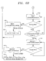
FIG. 6B is a second portion of the flow chart of FIG. 6A; and
FIG. 7 is a flow-chart representing a door open mode of operation for the combination cooking appliance of the present invention.
DETAILED DESCRIPTION OF THE PREFERRED EMBODIMENT
With initial reference to FIGS. 1–3, a cooking appliance constructed in accordance with the present invention is generally indicated at 2. As shown, cooking appliance 2 includes a base frame 3 to which is secured an outer cabinet shell 4 having top and opposing side panels 68. Cooking appliance 2 is also provided with a front face or wall 9 and a rear panel 10. Arranged at a lower portion of front wall 9 is an intake air vent 12 through which, as will be discussed more fully below, an ambient air flow enters into cabinet shell 4. In addition, cabinet shell 4 includes a plurality of air discharge vents, indicated generally at 14, arranged on side panel 7. Vents 14 enable cooling air to exit from within cooking appliance 2, thereby removing heat from within cabinet shell 4. Cabinet shell 4 is secured over base frame 3 through a plurality of fasteners 16, with the fasteners 16 arranged along front wall 9 being secured at tabs 17 (see FIG. 3).
As best seen in FIG. 2, arranged within cabinet shell 4 is a cooking chamber 20 having top, bottom, rear and opposing side walls 2125. In a manner known in the art, a door 29 is pivotally mounted to front wall 9 to selectively enable access to cooking chamber 20. Toward that end, door 29 includes a handle 30 and a window 31 for viewing the contents of cooking chamber 20 during a cooking operation. Although not shown, window 31 includes a screen that prevents microwave energy fields from escaping from within cooking chamber 20 during a cooking operation. In the embodiment shown, handle 30 is adapted to interconnect to upper and lower latching mechanisms 34 and 35 so as to retain door 29 in a closed position. In addition, latching mechanisms 34 and 35 serve as an interlock that prevents operation of cooking appliance 2 whenever door 29 is opened.
Cooking appliance 2 is shown to include upper and side control panels 39 and 40, each of which includes a respective set of control buttons or elements 41 and 42. The sets of control elements 41 and 42, in combination with a digital display 44 and a controller or CPU 45, enable a user to establish particular cooking operations for cooking appliance 2. For instance, control elements 41 can be used to establish the heating parameters of cooking appliance 2, while control elements 42 enable stored cooking times and/or operations to be readily selected. Since the general programming of cooking appliance 2 does not form part of the present invention, these features will not be described further herein.
As further shown in FIG. 2, cooking appliance 2 includes a plenum cover 62 arranged at an upper portion of cooking chamber 20. As will be discussed more fully below, plenum cover 62 includes a plurality of openings, indicated generally at 63, that enable an exhaust air flow to pass from cooking chamber 20. Arranged behind plenum cover 62 is a bifurcated air plenum 67 (see FIG. 4) that provides air flow management for cooking chamber 20 during a cooking operation. More specifically, an air emitter plate 72 extends rearward from a lower portion of plenum cover 62 to rear wall 23 of cooking chamber 20. In accordance with a preferred embodiment of the invention, air emitter plate 72 includes a plurality of strategically placed openings 73 that are exposed to a lower portion of bifurcated plenum 67. A radiant heating device 80, including first and second radiant heating elements 82 and 83 (see FIG. 2), preferably extends along air emitter plate 72. More specifically, radiant heating elements 82 and 83 are constituted by sheathed, electric resistive elements, each having a serpentine-like pattern that extends fore-to-aft across a section of air emitter plate 72. In the most preferred embodiment, each heating element 82, 83 is capable of delivering 900 watts of energy into cooking chamber 20. More preferably, each heating element 82, 83 is configured to produce 60 watts/in2 of power. Cooking appliance 2 also includes a convection air intake vent 85 having a plurality of convection air openings 86 positioned on rear wall 23 of cooking chamber 20.
As shown best with reference to FIGS. 3 and 4, cooking appliance 2 includes a microwave heating device 100 incorporating first and second magnetrons 102 and 103 (see FIG. 3) that are adapted to generate and direct a combined microwave energy field into cooking chamber 20. As seen in FIG. 4, first and second magnetrons 102 and 103 include respective first and second rotating antenna assemblies 107 and 108. Each rotating antenna assembly 107, 108 includes an antenna portion 110, 111, a housing portion 113, 114 and a gear member 116, 117 respectively. In accordance with a preferred form of the invention, antenna assemblies 107 and 108 are arranged below bottom wall 22 of cooking chamber 20. In further accordance with the invention, antenna portions 110 and 111 are rotated so as to develop a uniform, constructive standing microwave energy field within cooking chamber 20. That is, antenna assemblies 107 and 108 are rotated by a drive motor 120 having a drive gear 121 which is drivingly connected to each of gears 116 and 117 of antenna assemblies 107 and 108, preferably through a gear train (not shown).
Referring to FIG. 3, magnetrons 102 and 103 are arranged in a microwave housing portion 131 of cooking appliance 2. Microwave housing portion 131 includes an angled divider 133 and a vertical divider 134. Although not shown, vertical divider 134 is formed with an opening leading beneath magnetron 102. In order to prevent magnetrons 102 and 103 from overheating, cooking appliance 2 is provided with a microwave cooling system 135 that includes a blower assembly 136 which is drivingly connected to a drive motor 138 positioned within a duct 139. Duct 139 extends from drive motor 138 to an opening 141 arranged below angled divider 133. With this arrangement, activation of cooking appliance 2 causes drive motor 138 to rotate, whereby blower assembly 136 establishes a cooling air flow. The cooling air flow is guided through opening 141 toward magnetron 103 due to the presence of angled divider 133. The cooling air flow circulates about magnetron 103, through vertical divider 134, across magnetron 102 and up along angled divider 133, in order to provide a cooling effect for magnetrons 102 and 103, before exiting cooking appliance 2 through vents 14.
In addition to microwave cooling system 135, cooking appliance 2 includes an air intake system 160 having an associated drive motor 162 coupled to an impeller 163. Drive motor 162 rotates impeller 163 so as to draw in an ambient air flow A through intake air vent 12. Intake air vent 12 leads to an intake air duct 166, while passing about drive motor 120 for antenna assemblies 107 and 108. A majority of the air flow A is circulated within a rear control housing portion 170 in order to cool a plurality of electronic components 172, including a main control board 175 which is adapted to receive input and/or programming instructions through control elements 41, 42 in order to establish and set various cooking operations for cooking appliance 2.
In addition to driving impeller 163, drive motor 162 operates a convection fan 200 positioned within a convection fan housing 202 that, in the embodiment shown, is arranged behind rear wall 23 of cooking chamber 20. More specifically, convection fan 200 is drivingly connected for concurrent rotation with impeller 163 through a drive shaft 205 such that operation of drive motor 162 is translated to convection fan 200 to establish a convective air flow B. Convective air flow B is passed over a convection air heating element 210 and delivered into cooking chamber 20 through openings 73 in air emitter plate 72. More specifically, as will be discussed further below, convective air flow B is directed into bifurcated air plenum 67 before passing into cooking chamber 20.
In further accordance with the preferred form of the invention, bifurcated air plenum 67 includes an angled divider plate 216 that defines a tapered air delivery portion 220 and a corresponding tapered exhaust portion 221. In the embodiment shown, air delivery portion 220 is essentially defined by air emitter plate 72, angled divider plate 216 and part of rear wall 23, while exhaust portion 221 is defined by plenum cover 62, top wall 21 and angled divider plate 216. In any event, air flow B developed through operation of convection fan 200 is heated by heating element 210, directed into air delivery portion 220 of bifurcated air plenum 67 and then lead into cooking chamber 20 through openings 73. The tapering of air delivery portion 220 is provided so that air initially entering bifurcated air plenum 67 from convection fan 200 passes through openings 73 in air emitter plate 72 with substantially the same pressure as air reaching an end portion (not separately labeled) of tapered air delivery portion 220.
As a portion of the cooking operation is constituted by convection heating, convective air flow B circulates about cooking chamber 20. This heated air flow has been found to particularly enhance the even cooking of a food item. As further represented in FIG. 4, a first portion of convective air flow B passes into convection air intake vent 85 through openings 86. The convective air flow B is heated/reheated by heating element 210 before being passed back into cooking chamber 20. At the same time, a second, preferably smaller portion of convective air flow B passes through openings 63 in plenum cover 62 and is directed out of cooking appliance 2. More specifically, plenum cover 62 leads into tapered exhaust portion 221. The exhaust air flow D entering into tapered exhaust portion 221 is passed upward into an exhaust duct 229 before exiting through an exhaust outlet 230 that, in the embodiment shown, is arranged at an upper rear portion of cooking appliance 2. To replace the lost air flow, convection fan 200 preferably draws or siphons a portion of air flow A. For this purpose, one or more openings 235 are provided in duct 166 in order to introduce fresh ambient air to the overall, circulating air flow. In this manner, certain cooking effluents, including moisture and steam, exit cooking chamber 20 through exhaust outlet 230, while a fresh supply of air is introduced into the remaining, recirculated air flow due to the presence of opening(s) 235.
In further accordance with the present invention, cooking appliance 2 includes a conductive heating device 250 that, in the most preferred form of the invention, defines bottom wall 22 of cooking chamber 20. Conductive heating device 250 is preferably constituted by a ceramic stone plate adapted to support food items within cooking chamber 20. Conductive heating device 250 advantageously provides a thermal conduction path for heating and browning of a food item. More specifically, upon activation of cooking appliance 2, radiant heat produced by heating elements 82 and 83 combines with convective air flow B generated by convection fan 200 to heat conduction heating device 250. Conductive heating device 250 is transparent to microwave energy so that microwave energy fields emitted by magnetrons 102 and 103 pass upward into cooking chamber 20 and further contribute to the overall cooking operation. In further accordance with the invention, conductive heating device 250 is supported upon a plurality of support brackets, such as those indicated at 255 and 256, to enable or facilitate removal of conductive heating device 250 for cleaning or other purposes.
With particular reference to FIG. 5, air emitter plate 72 is preferably formed from anodized cast aluminum and provided with a pair of fore-to-aft extending recessed channels 280. Recessed channels 280 are provided with a plurality of openings 284. Heating elements 82 and 83 are nested within recessed channels 280 adjacent openings 284. As shown, each heating element 82, 83 includes a pair of electrodes 286 and 287 spaced from side walls 24 and 25 by an insulator 290. With this mounting arrangement, not only do heating elements 82 and 83 provide a source of radiant heat, but convective air flow B passing through openings 284 is heated by the additional thermal energy generated by heating elements 82 and 83 as air flow B passes from air delivery portion 210 of air plenum 67 into cooking chamber 20. Therefore, by being routed between, across and around respective ones of the various strategically placed openings 284, heating elements 82 and 83 evenly distribute thermal and infrared energy to the food being cooked.
With this overall combined cooking arrangement, a food item, for example, an open-faced sandwich placed within cooking chamber 20, can be exposed to a four-way combination cooking operation, i.e. radiant, microwave, convection and conductive heating techniques. The combination of the aforementioned heating techniques serves to cook the food item in an expeditious manner, while maintaining the required food quality. In addition, combining the aforementioned heating techniques enables cooking appliance 2 to be readily adapted to cook a wide range of food items in an efficient and effective manner, while also establishing an overall compact unit.
Having described a preferred construction of cooking appliance 2 of the present invention, reference will now be made to FIGS. 6–7 in describing a preferred control algorithm indicated generally at 390. Initially, cooking appliance 2 is activated through manipulating one of the plurality of control elements 41 or 42 to start a cooking operation as represented in step 400. At this point, CPU 45 initiates a preheat mode indicated at step 410. During the pre-heat mode (step 410), CPU 45 preferably activates radiant device 80, convention fan 200 and convection heating element 210 at full power in order to establish a selected temperature within oven cavity 20. While in the preheat mode, CPU 45 checks to see whether door 29 has been opened in step 420. In connection with the invention, numerous methods of sensing whether door 29 is or has been opened can be employed. One preferred method is set forth in U.S. patent application Ser. No. 10/991,941 entitled “Door Position Sensing System for Cooking Appliance Including Combination Heating System” filed Nov. 19, 2004, which is incorporated herein by reference. In any event, if CPU 45 determines that door 29 has been opened, control algorithm 390 transitions into a door open mode in step 430, with the door open mode being detailed in FIG. 7. If door 29 is opened at an initial stage of the pre-heat or cooking operation, the door open mode (step 430) commences at a normal door open mode in step 432. During the normal door open mode (step 432), CPU 45 operates radiant device 80, convection fan 20 and convection heating element 210 at a first power level or setting. Depending upon particular selections made, the first power level or setting can be set to simply maintain the selected temperature in oven cavity 20 or at lower settings in order to reduce heat loss when door 29 is opened. At this point, CPU 45 checks whether door 29 has closed in step 433.
If door 29 has not been closed after expiration of a first predetermined door open time as represented in step 434, CPU 45 shifts to a first low power door open mode in step 450. When operating in the first low power door open mode (step 450), radiant device 80, convection fan 20 and convection heating element 210 are activated at a first low power or second setting. In this manner, the oven is powered down slightly to conserve energy, but not so much so that re-establishing the selected temperature will substantially extend the cooking process. While in the first low power door open mode (step 450), CPU 45 determines whether door 20 remains open in step 451. If door 29 is not closed after a second predetermined period of time (step 452), CPU 45 shifts to a second low power door open mode in step 455. While in the second low power door open mode (step 455), CPU 45 operates radiant device 80, convection fan 20 and convection heating element 210 at a second low power level or third setting to further conserve energy. At this point, CPU 45 will maintain the second low power door open mode of operation until door 29 is closed, whereupon operation of cooking appliance 2 returns to control algorithm 390.
After returning to control algorithm 390, CPU 45 determines whether the selected temperature has been established in oven cavity 20 in step 440. If not, cooking appliance 2 continues pre-heating. However, once the selected temperature has been reached, CPU 45 automatically shifts to a ready mode of operation as indicated in step 460. During the ready mode (step 460), the heat output of radiant device 80 and the speed of convection fan 200 can be set to any desired level (preferably reduced), while convection heating element 210 cycles, to maintain the selected temperature. Preferably, the outputs of radiant device 80 and convection fan 200 are established by phase firing corresponding semiconductors 462 and 463 that are operatively associated with radiant device 80 and convection fan 200 (see FIG. 1). In addition to lowering the heat output of radiant device 80 and speed of convection fan 200, the output of convection heating element 210 is reduced, preferably by cycling an associated relay 464 (also see FIG. 1). In the ready mode (step 460), CPU 45 also determines whether door 29 has been opened in step 470. If open, operational control algorithm 390 shifts to the door open mode (step 430) and, when door 29 is sensed to be closed, a cooking operation is initiated to cook a food item within oven cavity 20. At this point, it should be noted that, in addition to radiant device 80, convection fan 200 and convection heating element 210, microwave cooking techniques can be employed through the activation of microwave heating device 100. In fact, a wide range of heating sources could be employed, either individually or in combination.
If it is determined that door 29 is not open in the ready mode (step 470 in FIG. 6A), CPU 45 senses whether a first time period has expired in step 480. CPU 45 can sense the expiration of the first time period using a variety of methods, such as through the use of an incremental or decremental counter, other timing devices or the like. If the first time period has not yet expired, cooking appliance 2 continues operation in the ready mode. If, however, the first time period has expired, CPU 45 automatically transitions to a first low power mode in step 490 to conserve energy (see FIG. 6B).
In the first low power mode (step 490), the heat output by radiant device 80 and the speed of convection fan 200 are once again reduced by phase firing semiconductors 462 and 463 associated with radiant device 80 and convection fan 200. Likewise, the heat output by convection heating element 210 is also reduced, preferably by cycling relay 464. While in the first low power mode (step 490), CPU 45 again determines whether door 29 has been opened in step 500. If so, control algorithm 390 shifts to the first low power door open mode (step 450). Once door 29 is closed, the first low power door open mode (step 450) shifts back to the control algorithm 390. At the same time, an overall cook time is adjusted in step 503 to account for any heat that may have escaped from oven cavity 20 when door 29 was open. If door 29 has not been opened after a second predetermined period of time when checked in step 510, CPU 45 automatically switches to a second low power mode of operation in step 520.
In a manner similar to that described above, when in the second low power mode (step 520), the heat output by radiant device 80 and speed of convection fan 200 are again reduced by phase firing semiconductors 462 and 463 and the heat output by convection heating element 210 is reduced by cycling relay 464. In this manner, the energy consumed by cooking appliance 2 can be further reduced in the event that a food item is not placed within oven cavity 20 after an extended period of time. While in the second low power mode, CPU 45 senses whether door 29 has been opened in step 530. If so, control algorithm 390 shifts to the second low power door open mode (step 455).
In accordance with the most preferred embodiment of the invention, if door 29 is opened while in the second low power door open mode (step 455), display 44 is flashed and control button elements 41 and 42 are locked out (step 532) until CPU 45 operates radiant device 80, convection fan 200 and convection heating element 210 to re-establish the preset or selected oven cavity temperature. If door 29 is not opened while in the second low power door open mode (step 455), cooking appliance continues to operate in a manner so as to conserve the overall energy consumed by the various heating devices.
In further accordance with the most preferred embodiment of the invention, each of the upper and lower temperature limits associated with the ready mode (step 460), the first low power mode (step 490) and the second low power mode (step 520) is user adjustable. That is, while the initial values are preferably pre-set, the end user can adjust and tailor operation of the cooking appliance to suit particular needs and operating environments. Likewise, each of the various time delays can be adjusted to suit specific needs of the end user. In this manner, the cooking appliance can be individually tailored, while still minimizing the consumption of energy.
Although described with reference to a preferred embodiment of the present invention, it should be readily apparent to one of ordinary skill in the art that various changes and/or modifications can be made to the invention without departing from the spirit thereof. For instance, although preferred operations are established for the convection heater, radiant heater and convection fan throughout door open conditions, it should be realized that the convection heater, radiant heater and convection fan could be adjusted to various levels as desired. That is, they can be increased to maintain cavity temperature or reduced to minimize the escaping of heat depending on the desired operation. In general, the invention is only intended to be limited by the scope of the following claims.

Claims (38)

1. A cooking appliance comprising:
an oven cavity including top, bottom, rear and opposing side walls that define a frontal opening;
a door pivotally mounted relative to the oven cavity for selectively closing the frontal opening;
at least one heating device for heating the oven cavity;
a control element for selecting a desired temperature for the oven cavity; and
a controller for selectively operating the at least one heating device in one of a plurality of operational modes based upon an initial selected oven cavity temperature and a time in which the door is in a predetermined position.
2. The cooking appliance according to claim 1, wherein the operational modes include a pre-heat mode, a ready mode, a first low power mode and a second low power mode.
3. The cooking appliance according to claim 2, wherein the at least one heating device includes a radiant heating device arranged in the oven cavity, a convection fan for directing a convective airflow into the oven cavity, and a convection heating device for heating the convective airflow.
4. The cooking appliance according to claim 3 wherein, during the pre-heat mode, the controller operates each of the radiant heating device, the convection fan and the convection heating device at full power so as to establish a selected temperature in the oven cavity.
5. The cooking appliance according to claim 4, wherein the controller automatically transitions from the pre-heat mode to the ready mode once the selected temperature is established in the oven cavity.
6. The cooking appliance according to claim 4, wherein, during the ready mode, the controller reduces both an amount of heat output by the radiant heating device and a speed of the convection fan, while cycling operation of the convection heating device, to maintain the selected temperature.
7. The cooking appliance according to claim 6, wherein the controller maintains the selected temperature of the oven cavity between an upper temperature limit and a lower temperature limit, said upper and lower temperature limits being associated with the selected temperature.
8. The cooking appliance according to claim 7, wherein the upper and lower temperature limits are adjustable.
9. The cooking appliance according to claim 3, wherein the controller automatically transitions from operating in the ready mode to operating in the first low power mode if the door of the appliance is not opened for a predetermined period of time.
10. The cooking appliance according to claim 9, wherein the predetermined period of time is adjustable.
11. The cooking appliance according to claim 9, wherein, during the first low power mode, the controller automatically reduces both an amount of heat output by the radiant heating device and a speed of the convection fan, while cycling operation of the convection heating device, to establish a first low temperature, said first low temperature being lower than the selected temperature.
12. The cooking appliance according to claim 11, wherein the controller maintains the first low temperature of the oven cavity between an upper temperature limit and a lower temperature limit, said upper and lower temperature limits being associated with the first low temperature.
13. The cooking appliance according to claim 12, wherein the upper and lower temperature limits associated with the first low temperature are adjustable.
14. The cooking appliance according to claim 11, wherein the controller automatically transitions from operating in the first low power mode to operating in the second low power mode if the door of the appliance is not opened for a predetermined period of time, said predetermined period of time being associated with the first low power mode.
15. The cooking appliance according to claim 14, wherein the predetermined period of time associated with the first low power mode is adjustable.
16. The cooking appliance according to claim 14, wherein, during the second low power mode, the controller reduces both an amount of heat output by the radiant heating device and a speed of the convection fan while cycling operation of the convection heating device, to establish a second low temperature, said second low temperature being lower than the first low temperature.
17. The cooking appliance according to claim 16, wherein the controller maintains the second low temperature of the oven cavity between an upper temperature limit and a lower temperature limit, said upper and lower temperature limits being associated with the second low temperature.
18. The cooking appliance according to claim 17, wherein the upper and lower temperature limits associated with the second low temperature are adjustable.
19. The cooking appliance according to claim 16, wherein the controller phase fires a semi-conductor to reduce heat output by the radiant heating device.
20. The cooking appliance according to claim 16, wherein the controller phase fires a semi-conductor to reduce the speed of the convection fan.
21. The cooking device according to claim 16, wherein the controller signals a relay to cycle operation of the convection heater.
22. The cooking device according to claim 3, wherein the at least one heating device further includes a microwave heating device adapted to perform a portion of the cooking operation.
23. The cooking device according to claim 2, wherein the operational modes further include a first low power door open mode, said first low power door open mode being activated if the door is opened during the first low power mode.
24. The cooking device according to claim 23, wherein the controller automatically adjusts a cook time upon termination of the first low power door open mode.
25. The cooking device according to claim 23, wherein the operational modes further include a second low power door open mode, said second low power door open mode being activated if the door is opened during the second low power mode.
26. The cooking device according to claim 25, wherein the controller locks out the control element upon completion of the second low power door open mode, said control element remaining locked out until the oven cavity has returned to the desired temperature.
27. A cooking appliance comprising:
an oven cavity including top, bottom, rear and opposing side walls that define a frontal opening;
a door pivotally mounted relative to the oven cavity for selectively closing the frontal opening;
at least one heating device for heating the oven cavity;
a control element for selecting a desired temperature for the oven cavity; and
means for operating the at least one heating device in one of a plurality of distinct operational modes, with at least two of the plurality of operational modes being operable only when the door is open.
28. The cooking appliance according to claim 27, wherein the operational modes include a pre-heat mode, a ready mode, a first low power mode and a second low power mode, a first low power door open mode and a second low power door open mode.
29. The cooking device according to claim 28, wherein the controller automatically adjusts a cook time upon termination of the first low power door open mode.
30. The cooking device according to claim 28, wherein the controller locks out the control element upon completion of the second low power door open mode, said control element remaining locked out until the oven cavity has returned to the desired temperature.
31. A method of operating a cooking appliance having an oven cavity comprising:
selecting a desired temperature for a cooking operation through at least one control element;
initiating a pre-heat operational mode during which at least one heating device is operated at substantially full power to establish the desired temperature in the oven cavity;
switching to a ready mode after the desired temperature is established;
maintaining the desired temperature between upper and lower temperature limits;
sensing whether a door of the appliance has been opened;
switching to a first low power mode if the door of the appliance is not opened for a first predetermined period of time, wherein the at least one heating device is operated in the first low power mode so as to establish a temperature in the oven cavity which is lower than the desired temperature; and
switching to a second low power mode if the door of the appliance is not opened for a second predetermined period of time, said second low power mode establishing a temperature for the appliance which is lower than the temperature established in the first low power mode.
32. The method of claim 31, wherein the desired temperature is maintained between the upper and lower temperature limits by reducing a heat output level of a radiant heating device and a speed of a convection fan, while also cycling a convection heating device.
33. The method of claim 32, further comprising: independently adjusting each of the first and second predetermined periods of time.
34. The method of claim 32, wherein the heat output by the radiant heating device is reduced by phase firing a semi-conductor.
35. The method of claim 31, further comprising: switching to a first low power door open mode if the door of the appliance is opened during the first low power mode.
36. The method of claim 35, further comprising: automatically adjusting a cook time once the first low power door open mode is terminated.
37. The method of claim 31, further comprising: switching to a second low power door open mode if the door of the appliance is opened during the second low power mode.
38. The method of claim 37 wherein, following the second low power door open mode, the at least one control element is locked out until the oven cavity returns to the desired temperature.
US11/033,556 2005-01-12 2005-01-12 Operational modes for a cooking appliance employing combination cooking technology Expired - Fee Related US7009147B1 (en)

Priority Applications (1)

Application Number Priority Date Filing Date Title
US11/033,556 US7009147B1 (en) 2005-01-12 2005-01-12 Operational modes for a cooking appliance employing combination cooking technology

Applications Claiming Priority (1)

Application Number Priority Date Filing Date Title
US11/033,556 US7009147B1 (en) 2005-01-12 2005-01-12 Operational modes for a cooking appliance employing combination cooking technology

Publications (1)

Publication Number Publication Date
US7009147B1 true US7009147B1 (en) 2006-03-07

Family

ID=35966234

Family Applications (1)

Application Number Title Priority Date Filing Date
US11/033,556 Expired - Fee Related US7009147B1 (en) 2005-01-12 2005-01-12 Operational modes for a cooking appliance employing combination cooking technology

Country Status (1)

Country Link
US (1) US7009147B1 (en)

Cited By (40)

* Cited by examiner, † Cited by third party
Publication number Priority date Publication date Assignee Title
US20060070612A1 (en) * 2004-09-30 2006-04-06 Maytag Corporation Cooking appliance control system
US20060237424A1 (en) * 2003-03-27 2006-10-26 Bsh Bosch Und Siemens Hausgerate Gmbh Method for operating a baking oven
US20070246452A1 (en) * 2006-04-20 2007-10-25 Electrolux Home Products, Inc. Variable speed convection in cooking applications
WO2007128471A1 (en) * 2006-05-05 2007-11-15 Electrolux Home Products Corporation N.V. Cooking oven, especially household finishing oven
EP2005866A1 (en) * 2007-06-21 2008-12-24 Electrolux Home Products Corporation N.V. Method for cooking a dish
US20090095738A1 (en) * 2007-10-09 2009-04-16 Acp, Inc. Cooking Appliance Including Combination Heating System
US20100147825A1 (en) * 2008-12-16 2010-06-17 Whirlpool Corporation Priority controlled multi-fan convection oven
US20100147824A1 (en) * 2008-12-16 2010-06-17 Whirlpool Corporation Convection cooking in multi-fan convection oven
US20100270293A1 (en) * 2007-10-09 2010-10-28 Acp, Inc. Air Circuit for Cooking Appliance Including Combination Heating System
US20100282097A1 (en) * 2007-10-09 2010-11-11 Acp, Inc. Temperature Control for Cooking Appliance Including Combination Heating System
DE102009024546A1 (en) * 2009-06-08 2010-12-09 Convotherm Elektrogeräte GmbH Cooking device i.e. hot-air steamer, for use in commercial kitchen in e.g. system catering industry, has cooking device component e.g. aerator, that assumes energy saving mode while reaching target temperature, in standby mode
EP2009958A3 (en) * 2007-06-25 2011-03-30 Daewoo Electronics Corporation Method of preheating microwave oven
US20110088682A1 (en) * 2007-11-16 2011-04-21 Wolfedale Engineering Limited Temperature control apparatus and method for a barbeque grill
US20130284161A1 (en) * 2012-04-26 2013-10-31 General Electric Company Oven appliance with features for selecting convection air flow direction
US20160097543A1 (en) * 2014-10-07 2016-04-07 General Electric Company Oven preheat boost using cooktop lockout
US20160116171A1 (en) * 2014-10-22 2016-04-28 General Electric Company Oven airflow control
US20160166111A1 (en) * 2013-07-09 2016-06-16 Strix Limited Apparatus for heating food
US20160205728A1 (en) * 2015-01-13 2016-07-14 General Electric Company Microwave appliances
US9874358B2 (en) 2015-05-05 2018-01-23 Appliance Innovation, Inc. Oven based on a combination of heated air and infrared heating element
CN107850314A (en) * 2015-09-02 2018-03-27 松下知识产权经营株式会社 Heating device
CN109497111A (en) * 2018-11-16 2019-03-22 新麦机械(中国)有限公司 A kind of food bakes and banks up with earth system and its control method
US10281156B2 (en) * 2013-04-23 2019-05-07 Alto-Shaam, Inc. Zero clearance combination oven
US20190231126A1 (en) * 2017-08-09 2019-08-01 Sharkninja Operating Llc Cooking device and components thereof
USD873602S1 (en) 2018-08-09 2020-01-28 Sharkninja Operating Llc Lid part of a food preparation device
USD874211S1 (en) 2018-08-09 2020-02-04 Sharkninja Operating Llc Food preparation device and parts thereof
USD903414S1 (en) 2018-08-09 2020-12-01 Sharkninja Operating Llc Cooking basket
USD914436S1 (en) 2018-06-19 2021-03-30 Sharkninja Operating Llc Air diffuser with food preparation pot
USD918654S1 (en) 2019-06-06 2021-05-11 Sharkninja Operating Llc Grill plate
USD922126S1 (en) 2019-06-06 2021-06-15 Sharkninja Operating Llc User interface for a food preparation device
US11033146B2 (en) 2019-02-25 2021-06-15 Sharkninja Operating Llc Cooking device and components thereof
US11134808B2 (en) 2020-03-30 2021-10-05 Sharkninja Operating Llc Cooking device and components thereof
USD932833S1 (en) 2018-08-09 2021-10-12 Sharkninja Operating Llc Reversible cooking rack
US20220160169A1 (en) * 2019-01-24 2022-05-26 Breville Pty Limited User interface for a cooking appliance
CN114641099A (en) * 2022-03-09 2022-06-17 广东精装照明有限公司 Electric ceramic stove integrated circuit and electric ceramic stove
US20230038969A1 (en) * 2012-08-29 2023-02-09 Samsung Electronics Co., Ltd. Cooking apparatus and control method thereof
US11604027B2 (en) * 2018-06-21 2023-03-14 Cfa Properties, Inc. Modular humidity control and heat preservation system
US11639797B2 (en) 2015-05-05 2023-05-02 Ovention, Inc. Cooking oven having an active vent
RU2801259C2 (en) * 2019-01-24 2023-08-04 Бревилль Пти Лимитед Food cooking device
US11751710B2 (en) 2019-02-25 2023-09-12 Sharkninja Operating Llc Guard for cooking system
US11918153B2 (en) 2018-06-21 2024-03-05 Cfa Properties, Inc. Food transportation and humidity control elements

Citations (18)

* Cited by examiner, † Cited by third party
Publication number Priority date Publication date Assignee Title
US3627959A (en) 1970-03-19 1971-12-14 Sage Laboratories Magnetic latching and switching
US3784776A (en) 1970-04-20 1974-01-08 Tokyo Shibaura Electric Co Electromagnetic locking mechanism for a microwave oven
US3823294A (en) 1970-08-31 1974-07-09 Gen Corp Door locking system for an electrical apparatus
US4054769A (en) 1976-03-04 1977-10-18 The Tappan Company Microwave oven interlock switch safety
US4096370A (en) 1977-06-15 1978-06-20 Litton Systems, Inc. Microwave oven door interlock switch system
US4117294A (en) 1975-06-12 1978-09-26 U.S. Philips Corporation Safety arrangement for microwave ovens
DE3236290A1 (en) 1982-09-30 1984-04-05 Bosch-Siemens Hausgeräte GmbH, 7000 Stuttgart Device for monitoring the closed state of microwave oven doors
EP0397209A2 (en) 1989-05-12 1990-11-14 VOGT electronic Aktiengesellschaft Electronic door surveillance of microwave ovens
EP0456846A1 (en) 1988-12-02 1991-11-21 VOGT electronic Aktiengesellschaft Electronic safety-device for a microwave oven door
EP0550897A2 (en) 1991-12-31 1993-07-14 Daewoo Electronics Co., Ltd Microwave oven door control device
JP2000164336A (en) * 1998-11-30 2000-06-16 Matsushita Electric Ind Co Ltd Heating device
US6087643A (en) * 1997-06-19 2000-07-11 Daewoo Electronics Co., Ltd. Method for controlling cavity lamp of microwave oven
US6331699B1 (en) * 1998-11-19 2001-12-18 Sharp Kabushiki Kaisha Microwave heating apparatus requiring reduced power in a standby state
US6337468B1 (en) 1998-07-14 2002-01-08 General Electric Company Rapid recovery oven control and method
US20030024925A1 (en) 2001-01-11 2003-02-06 Graves Todd Vincent Speedcooking oven including a convection / bake mode
US6521870B2 (en) 2001-01-11 2003-02-18 General Electric Company Thermal/convection oven including halogen lamps
US6528772B1 (en) 1999-01-13 2003-03-04 General Electric Company Speed cooking oven and control apparatus
US6570138B2 (en) * 2001-02-15 2003-05-27 Alto-Shaam, Inc. Method and apparatus for anticipating rapid temperature fluctuations within an enclosed heated cavity

Patent Citations (19)

* Cited by examiner, † Cited by third party
Publication number Priority date Publication date Assignee Title
US3627959A (en) 1970-03-19 1971-12-14 Sage Laboratories Magnetic latching and switching
US3784776A (en) 1970-04-20 1974-01-08 Tokyo Shibaura Electric Co Electromagnetic locking mechanism for a microwave oven
US3823294A (en) 1970-08-31 1974-07-09 Gen Corp Door locking system for an electrical apparatus
US4117294A (en) 1975-06-12 1978-09-26 U.S. Philips Corporation Safety arrangement for microwave ovens
US4054769A (en) 1976-03-04 1977-10-18 The Tappan Company Microwave oven interlock switch safety
US4096370A (en) 1977-06-15 1978-06-20 Litton Systems, Inc. Microwave oven door interlock switch system
DE3236290A1 (en) 1982-09-30 1984-04-05 Bosch-Siemens Hausgeräte GmbH, 7000 Stuttgart Device for monitoring the closed state of microwave oven doors
EP0456846A1 (en) 1988-12-02 1991-11-21 VOGT electronic Aktiengesellschaft Electronic safety-device for a microwave oven door
EP0397209A2 (en) 1989-05-12 1990-11-14 VOGT electronic Aktiengesellschaft Electronic door surveillance of microwave ovens
EP0550897A2 (en) 1991-12-31 1993-07-14 Daewoo Electronics Co., Ltd Microwave oven door control device
US5293020A (en) 1991-12-31 1994-03-08 Daewoo Electronics Co., Ltd. Microwave oven door control device
US6087643A (en) * 1997-06-19 2000-07-11 Daewoo Electronics Co., Ltd. Method for controlling cavity lamp of microwave oven
US6337468B1 (en) 1998-07-14 2002-01-08 General Electric Company Rapid recovery oven control and method
US6331699B1 (en) * 1998-11-19 2001-12-18 Sharp Kabushiki Kaisha Microwave heating apparatus requiring reduced power in a standby state
JP2000164336A (en) * 1998-11-30 2000-06-16 Matsushita Electric Ind Co Ltd Heating device
US6528772B1 (en) 1999-01-13 2003-03-04 General Electric Company Speed cooking oven and control apparatus
US20030024925A1 (en) 2001-01-11 2003-02-06 Graves Todd Vincent Speedcooking oven including a convection / bake mode
US6521870B2 (en) 2001-01-11 2003-02-18 General Electric Company Thermal/convection oven including halogen lamps
US6570138B2 (en) * 2001-02-15 2003-05-27 Alto-Shaam, Inc. Method and apparatus for anticipating rapid temperature fluctuations within an enclosed heated cavity

Cited By (119)

* Cited by examiner, † Cited by third party
Publication number Priority date Publication date Assignee Title
US20060237424A1 (en) * 2003-03-27 2006-10-26 Bsh Bosch Und Siemens Hausgerate Gmbh Method for operating a baking oven
US7309846B2 (en) * 2003-03-27 2007-12-18 Bsh Bosch Und Siemens Hausgeraete Gmbh Method for operating a baking oven
US20060070612A1 (en) * 2004-09-30 2006-04-06 Maytag Corporation Cooking appliance control system
US7126088B2 (en) * 2004-09-30 2006-10-24 Maytag Corporation Cooking appliance control system
US20070246452A1 (en) * 2006-04-20 2007-10-25 Electrolux Home Products, Inc. Variable speed convection in cooking applications
WO2007128471A1 (en) * 2006-05-05 2007-11-15 Electrolux Home Products Corporation N.V. Cooking oven, especially household finishing oven
US20090064986A1 (en) * 2006-05-05 2009-03-12 Electrolux Home Products Corporation N.V. Cooking oven, especially household finishing oven
AU2007247452B2 (en) * 2006-05-05 2011-01-27 Electrolux Home Products Corporation N.V. Cooking oven, especially household finishing oven
WO2008137307A3 (en) * 2007-05-07 2010-11-25 Electrolux Home Products Inc. Variable speed convection in cooking applications
WO2008137307A2 (en) * 2007-05-07 2008-11-13 Electrolux Home Products Inc. Variable speed convection in cooking applications
AU2008247927B2 (en) * 2007-05-07 2012-09-13 Electrolux Home Products Inc. Variable speed convection in cooking applications
CN102027294B (en) * 2007-05-07 2013-02-13 伊莱克斯家用产品公司 Variable speed convection in cooking applications
EP2005866A1 (en) * 2007-06-21 2008-12-24 Electrolux Home Products Corporation N.V. Method for cooking a dish
EP2009958A3 (en) * 2007-06-25 2011-03-30 Daewoo Electronics Corporation Method of preheating microwave oven
US20100282097A1 (en) * 2007-10-09 2010-11-11 Acp, Inc. Temperature Control for Cooking Appliance Including Combination Heating System
US20100270293A1 (en) * 2007-10-09 2010-10-28 Acp, Inc. Air Circuit for Cooking Appliance Including Combination Heating System
US9006619B2 (en) 2007-10-09 2015-04-14 Acp, Inc. Cooking appliance including combination heating system
US20090095738A1 (en) * 2007-10-09 2009-04-16 Acp, Inc. Cooking Appliance Including Combination Heating System
US8294070B2 (en) 2007-10-09 2012-10-23 Acp, Inc. Air circuit for cooking appliance including combination heating system
US8642928B2 (en) 2007-10-09 2014-02-04 Acp, Inc. Temperature control for cooking appliance including combination heating system
US9329606B2 (en) * 2007-11-16 2016-05-03 Wolfedale Engineering Limited Temperature control apparatus and method for a barbeque grill
US10180691B2 (en) 2007-11-16 2019-01-15 Wolfedale Engineering Limited Temperature control apparatus for a barbeque grill
US20110088682A1 (en) * 2007-11-16 2011-04-21 Wolfedale Engineering Limited Temperature control apparatus and method for a barbeque grill
US20100147825A1 (en) * 2008-12-16 2010-06-17 Whirlpool Corporation Priority controlled multi-fan convection oven
US20100147824A1 (en) * 2008-12-16 2010-06-17 Whirlpool Corporation Convection cooking in multi-fan convection oven
US8304695B2 (en) 2008-12-16 2012-11-06 Whirlpool Corporation Priority controlled multi-fan convection oven
US8097833B2 (en) 2008-12-16 2012-01-17 Whirlpool Corporation Convection cooking in multi-fan convection oven
DE102009024546A1 (en) * 2009-06-08 2010-12-09 Convotherm Elektrogeräte GmbH Cooking device i.e. hot-air steamer, for use in commercial kitchen in e.g. system catering industry, has cooking device component e.g. aerator, that assumes energy saving mode while reaching target temperature, in standby mode
US20130284161A1 (en) * 2012-04-26 2013-10-31 General Electric Company Oven appliance with features for selecting convection air flow direction
US20230038969A1 (en) * 2012-08-29 2023-02-09 Samsung Electronics Co., Ltd. Cooking apparatus and control method thereof
US10281156B2 (en) * 2013-04-23 2019-05-07 Alto-Shaam, Inc. Zero clearance combination oven
US20160166111A1 (en) * 2013-07-09 2016-06-16 Strix Limited Apparatus for heating food
US10682014B2 (en) * 2013-07-09 2020-06-16 Strix Limited Apparatus for heating food
US20160097543A1 (en) * 2014-10-07 2016-04-07 General Electric Company Oven preheat boost using cooktop lockout
US9506657B2 (en) * 2014-10-07 2016-11-29 Haier U.S. Appliance Solutions, Inc. Oven preheat boost using cooktop lockout
US20160116171A1 (en) * 2014-10-22 2016-04-28 General Electric Company Oven airflow control
US20160205728A1 (en) * 2015-01-13 2016-07-14 General Electric Company Microwave appliances
US11639797B2 (en) 2015-05-05 2023-05-02 Ovention, Inc. Cooking oven having an active vent
US9874358B2 (en) 2015-05-05 2018-01-23 Appliance Innovation, Inc. Oven based on a combination of heated air and infrared heating element
EP3346189A4 (en) * 2015-09-02 2018-08-29 Panasonic Intellectual Property Management Co., Ltd. Cooking apparatus
US20180119962A1 (en) * 2015-09-02 2018-05-03 Panasonic intellectual property Management co., Ltd Cooking apparatus
CN107850314A (en) * 2015-09-02 2018-03-27 松下知识产权经营株式会社 Heating device
US10895385B2 (en) 2015-09-02 2021-01-19 Panasonic Intellectual Property Management Co., Ltd. Cooking apparatus
US10674868B2 (en) 2017-08-09 2020-06-09 Sharkninja Operating Llc Cooking device and components thereof
US10390656B2 (en) 2017-08-09 2019-08-27 Sharkninja Operating Llc Cooking device and components thereof
US10413121B2 (en) 2017-08-09 2019-09-17 Sharkninja Operating Llc Cooking device and components thereof
US10413122B2 (en) 2017-08-09 2019-09-17 Sharkninja Operating Llc Cooking device and components thereof
US10485378B2 (en) 2017-08-09 2019-11-26 Sharkninja Operating Llc Cooking device and components thereof
US11109710B2 (en) 2017-08-09 2021-09-07 Sharkninja Operating Llc Cooking device and components thereof
US11889950B2 (en) 2017-08-09 2024-02-06 Sharkninja Operating Llc Cooking device and components thereof
US11759048B2 (en) 2017-08-09 2023-09-19 Sharkninja Operating Llc Cooking device and components thereof
US11759049B2 (en) 2017-08-09 2023-09-19 Sharkninja Operating Llc Cooking device and components thereof
US11627834B2 (en) 2017-08-09 2023-04-18 Sharkninja Operating Llc Cooking system for cooking food
US11266267B2 (en) 2017-08-09 2022-03-08 Sharkninja Operating Llc Cooking device and components thereof
US20190231126A1 (en) * 2017-08-09 2019-08-01 Sharkninja Operating Llc Cooking device and components thereof
US10646070B2 (en) 2017-08-09 2020-05-12 Sharkninja Operating Llc Cooking device and components thereof
US10653270B2 (en) 2017-08-09 2020-05-19 Sharkninja Operating Llc Cooking device and components thereof
US10660472B2 (en) 2017-08-09 2020-05-26 Sharkninja Operating Llc Cooking device and components thereof
US10405697B2 (en) 2017-08-09 2019-09-10 Sharkninja Operating Llc Cooking device and components thereof
US10682011B2 (en) 2017-08-09 2020-06-16 Sharkninja Operating Llc Cooking device and components thereof
US11266268B2 (en) 2017-08-09 2022-03-08 Sharkninja Operating Llc Cooking device and components thereof
US11547242B2 (en) 2017-08-09 2023-01-10 Sharkninja Operating Llc Cooking device and components thereof
US10405698B2 (en) 2017-08-09 2019-09-10 Sharkninja Operating Llc Cooking device and components thereof
US11547243B2 (en) 2017-08-09 2023-01-10 Sharkninja Operating Llc Cooking device and components thereof
US20190231127A1 (en) * 2017-08-09 2019-08-01 Sharkninja Operating Llc Cooking device and components thereof
US11278151B2 (en) 2017-08-09 2022-03-22 Sharkninja Operating Llc Cooking device and components thereof
US11089903B2 (en) 2017-08-09 2021-08-17 Sharkninja Operating Llc Cooking device and components thereof
US11445856B2 (en) 2017-08-09 2022-09-20 Sharkninja Operating Llc Cooking device and components thereof
US11399657B2 (en) 2017-08-09 2022-08-02 Sharkninja Operating Llc Cooking device and components thereof
US11363910B2 (en) * 2017-08-09 2022-06-21 Sharkninja Operating Llc Cooking device and components thereof
US11304561B2 (en) * 2017-08-09 2022-04-19 Sharkninja Operating Llc Cooking device and components thereof
US11089902B2 (en) 2017-08-09 2021-08-17 Sharkninja Operating Llc Cooking device and components thereof
USD948938S1 (en) 2018-06-19 2022-04-19 Sharkninja Operating Llc Air diffuser
USD914447S1 (en) 2018-06-19 2021-03-30 Sharkninja Operating Llc Air diffuser
USD914436S1 (en) 2018-06-19 2021-03-30 Sharkninja Operating Llc Air diffuser with food preparation pot
US11604027B2 (en) * 2018-06-21 2023-03-14 Cfa Properties, Inc. Modular humidity control and heat preservation system
US11918153B2 (en) 2018-06-21 2024-03-05 Cfa Properties, Inc. Food transportation and humidity control elements
USD903415S1 (en) 2018-08-09 2020-12-01 Sharkninja Operating Llc Cooking basket
USD903413S1 (en) 2018-08-09 2020-12-01 Sharkninja Operating Llc Cooking basket
USD873602S1 (en) 2018-08-09 2020-01-28 Sharkninja Operating Llc Lid part of a food preparation device
USD932833S1 (en) 2018-08-09 2021-10-12 Sharkninja Operating Llc Reversible cooking rack
USD874211S1 (en) 2018-08-09 2020-02-04 Sharkninja Operating Llc Food preparation device and parts thereof
USD934027S1 (en) 2018-08-09 2021-10-26 Sharkninja Operating Llc Reversible cooking rack
USD876874S1 (en) 2018-08-09 2020-03-03 Sharkninja Operating Llc User interface for a food preparation device
USD935259S1 (en) 2018-08-09 2021-11-09 Sharkninja Operating Llc Food preparation device
USD940503S1 (en) 2018-08-09 2022-01-11 Sharkninja Operating Llc Cooking basket
USD941090S1 (en) 2018-08-09 2022-01-18 Sharkninja Operating Llc Cooking basket
USD929794S1 (en) 2018-08-09 2021-09-07 Sharkninja Operating Llc Food preparation device
USD929793S1 (en) 2018-08-09 2021-09-07 Sharkninja Operating Llc Food preparation device
USD929173S1 (en) 2018-08-09 2021-08-31 Sharkninja Operating Llc Food preparation device
USD883015S1 (en) 2018-08-09 2020-05-05 Sharkninja Operating Llc Food preparation device and parts thereof
USD883016S1 (en) 2018-08-09 2020-05-05 Sharkninja Operating Llc Food preparation device and parts thereof
USD883014S1 (en) 2018-08-09 2020-05-05 Sharkninja Operating Llc Food preparation device
USD883017S1 (en) 2018-08-09 2020-05-05 Sharkninja Operating Llc User interface for food preparation device
USD903414S1 (en) 2018-08-09 2020-12-01 Sharkninja Operating Llc Cooking basket
USD931680S1 (en) 2018-08-09 2021-09-28 Sharkninja Operating Llc Cooking basket
USD920732S1 (en) 2018-08-09 2021-06-01 Sharkninja Operating Llc Food preparation device
CN109497111B (en) * 2018-11-16 2023-09-29 新麦机械(中国)股份有限公司 Food baking system and control method thereof
CN109497111A (en) * 2018-11-16 2019-03-22 新麦机械(中国)有限公司 A kind of food bakes and banks up with earth system and its control method
US20220160169A1 (en) * 2019-01-24 2022-05-26 Breville Pty Limited User interface for a cooking appliance
RU2801259C2 (en) * 2019-01-24 2023-08-04 Бревилль Пти Лимитед Food cooking device
US11766152B2 (en) 2019-02-25 2023-09-26 Sharkninja Operating Llc Cooking device and components thereof
US11832761B2 (en) 2019-02-25 2023-12-05 Sharkninja Operating Llc Cooking device and components thereof
US11033146B2 (en) 2019-02-25 2021-06-15 Sharkninja Operating Llc Cooking device and components thereof
US11147415B2 (en) 2019-02-25 2021-10-19 Sharkninja Operating Llc Cooking device and components thereof
US11051654B2 (en) 2019-02-25 2021-07-06 Sharkninja Operating Llc Cooking device and components thereof
US11751710B2 (en) 2019-02-25 2023-09-12 Sharkninja Operating Llc Guard for cooking system
US11363911B2 (en) 2019-02-25 2022-06-21 Sharkninja Operating Llc Cooking device and components thereof
US11751722B2 (en) 2019-02-25 2023-09-12 Sharkninja Operating Llc Cooking device and components thereof
USD934631S1 (en) 2019-06-06 2021-11-02 Sharkninja Operating Llc Grill plate
USD918654S1 (en) 2019-06-06 2021-05-11 Sharkninja Operating Llc Grill plate
USD922126S1 (en) 2019-06-06 2021-06-15 Sharkninja Operating Llc User interface for a food preparation device
USD982375S1 (en) 2019-06-06 2023-04-04 Sharkninja Operating Llc Food preparation device
USD1015798S1 (en) 2019-06-06 2024-02-27 Sharkninja Operating Llc Food preparation device
US11678765B2 (en) 2020-03-30 2023-06-20 Sharkninja Operating Llc Cooking device and components thereof
US11647861B2 (en) 2020-03-30 2023-05-16 Sharkninja Operating Llc Cooking device and components thereof
US11134808B2 (en) 2020-03-30 2021-10-05 Sharkninja Operating Llc Cooking device and components thereof
CN114641099A (en) * 2022-03-09 2022-06-17 广东精装照明有限公司 Electric ceramic stove integrated circuit and electric ceramic stove
CN114641099B (en) * 2022-03-09 2024-02-20 广东精装照明有限公司 Electric ceramic stove integrated circuit and electric ceramic stove

Similar Documents

Publication Publication Date Title
US7009147B1 (en) Operational modes for a cooking appliance employing combination cooking technology
CA2446494C (en) Cooking appliance having accelerated cooking system
US6815644B1 (en) Multirack cooking in speedcook ovens
US7109447B2 (en) Control system for cooking appliance employing convection and radiant cooking
US7235763B2 (en) Cooking appliance including combination heating system
US9006619B2 (en) Cooking appliance including combination heating system
US8304695B2 (en) Priority controlled multi-fan convection oven
CA2459604C (en) Methods and apparatus for operating a speedcooking oven
US7109448B2 (en) Control system for cooking appliance employing radiant cooking
US8097833B2 (en) Convection cooking in multi-fan convection oven
US20070029312A1 (en) Electric oven and method of operating the same
KR20060070910A (en) An electric oven range
US20010004077A1 (en) Built-in microwave oven
US20100198410A1 (en) Method of controlling oven
CA2988304A1 (en) Cooking apparatus
CA2454010C (en) Ventilation system for a cooking appliance
US6881054B2 (en) Combination radiant/convection gas cooking appliance
CA2498788A1 (en) Door position sensing system for cooking appliance including combination heating system
JP2004093048A (en) Heating cookware
US20050236405A1 (en) Cold start control system for microwave cooking appliance
JP2009281637A (en) Cooking device
KR100999763B1 (en) Microwave oven and controlling methood of thereof
JP3878061B2 (en) Cooker
JPH05340542A (en) Heating cooker
KR101211585B1 (en) Microwave oven with controlling heater device

Legal Events

Date Code Title Description
FEPP Fee payment procedure

Free format text: PAYOR NUMBER ASSIGNED (ORIGINAL EVENT CODE: ASPN); ENTITY STATUS OF PATENT OWNER: LARGE ENTITY

AS Assignment

Owner name: MAYTAG CORPORATION, IOWA

Free format text: ASSIGNMENT OF ASSIGNORS INTEREST;ASSIGNOR:SCHULTE, ROBERT A.;REEL/FRAME:016159/0042

Effective date: 20041223

REMI Maintenance fee reminder mailed
LAPS Lapse for failure to pay maintenance fees
STCH Information on status: patent discontinuation

Free format text: PATENT EXPIRED DUE TO NONPAYMENT OF MAINTENANCE FEES UNDER 37 CFR 1.362

FP Lapsed due to failure to pay maintenance fee

Effective date: 20100307

AS Assignment

Owner name: ACP OF DELAWARE, INC., IOWA

Free format text: ASSIGNMENT OF ASSIGNORS INTEREST;ASSIGNOR:MAYTAG CORPORATION;REEL/FRAME:025744/0325

Effective date: 20060906