CROSS-REFERENCE TO OTHER APPLICATIONS
This application claims the benefit of U.S. Provisional Application No. 60/116,847, filed Jan. 22, 1999, which is incorporated herein by reference in its entirety.
The following applications of common assignee are related to the present application, and are incorporated herein by reference in their entireties:
“Method and System for Down-Converting Electromagnetic Signals,” Ser. No. 09/176,022, filed on Oct. 21, 1998.
“Method and System for Frequency Up-Conversion,” Ser. No. 09/176,154, filed on Oct. 21, 1998.
“Method and System for Ensuring Reception of a Communications Signal,” Ser. No. 09/176,415, filed on Oct. 21, 1998.
“Integrated Frequency Translation and Selectivity,” Ser. No. 09/175,966, filed on Oct. 21, 1998.
“Image-Reject Down-Converter and Embodiments Thereof, Such as the Family Radio Service,” Serial No. 09/476,091, filed Jan. 3, 2000.
“Analog Zero IF FM Decoder and Embodiments Thereof, Such as the Family Radio Service,” Serial No. 09/476,092, filed Jan. 3, 2000.
“Multi-Mode, Multi-Band Communication System,” Serial No. 09/476,330, filed Jan. 3, 2000.
BACKGROUND OF THE INVENTION
1. Field of the Invention
The present invention is generally directed toward receiver-transmitter systems referred to as Family Radio Service (FRS) units, although the invention is not limited to this embodiment. The Family Radio Service is one of the Citizens Band Radio Services. It is intended for the use of family, friends, and associates to communicate among themselves within a neighborhood or while on group outings. There are fourteen discreet FRS channels available for use on a “take turns” basis. The FRS unit channel frequencies are:
| | 1 | 462.5625 |
| | 2 | 462.5875 |
| | 3 | 462.6125 |
| | 4 | 462.6375 |
| | 5 | 462.6625 |
| | 6 | 462.6875 |
| | 7 | 462.7125 |
| | 8 | 467.5625 |
| | 9 | 467.5875 |
| | 10 | 467.6125 |
| | 11 | 467.6375 |
| | 12 | 467.6625 |
| | 13 | 467.6875 |
| | 14 | 467.7125 |
| | |
Other selected technical specifications are:
-
- (a) Frequency modulation (although phase modulation is allowed);
- (b) Frequency tolerance of each FRS unit must be maintained within 0.00025%;
- (c) The authorized bandwidth for an FRS unit is 12.5 kHz; and
- (d) Effective radiated power (ERP) shall not, under any condition of modulation, exceed 0.500 W.
The operating rules for the FRS are found at 47 C.F.R. 95.191–95.194. For additional technical information, see 47 C.F.R. 95.601–95.669.
2. Related Art
A variety of Family Radio Service (FRS) transceivers are commercially available. Generally, operation of a conventional FRS transceiver is limited to a single FRS channel.
SUMMARY OF THE INVENTION
Briefly stated, the invention is directed to a receiver having multi-mode and multi-band functionality and capabilities. According to the invention, the receiver is capable of selectively operating over a plurality of bands and channels. The receiver operates in a plurality of modes, including but not limited to a single band/channel mode, and a multiple band/channel mode. The receiver may form a portion of a transceiver. The transceiver may also include a transmitter. In an embodiment, the transceiver is a family radio service (FRS) unit, although the invention is not limited to this embodiment.
Further features and advantages of the invention, as well as various embodiments of the invention, are described in detail below with reference to the accompanying drawings.
BRIEF DESCRIPTION OF THE FIGURES
The present invention will be described with reference to the accompanying drawings, wherein:
FIG. 1 is a block diagram of a receiver according to an embodiment of the invention;
FIG. 2 is a block diagram of a receiver according to an alternative embodiment of the invention;
FIG. 3 is a flowchart of the invention when operating according to a single band/channel mode;
FIG. 4 is a flowchart of the invention when operating according to a multiple band/channel mode;
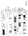
FIGS. 5A–5D depict some frequency allocations operable with the present invention;
FIG. 6 is a block diagram of a transceiver according to an embodiment of the invention; and
FIG. 7 illustrates an exemplary use scenario used to described the operation of an embodiment of the invention.
DETAILED DESCRIPTION OF THE PREFERRED EMBODIMENTS
Overview of the Invention
The invention is directed to a receiver having multi-mode and multi-band functionality and capabilities. According to the invention, the receiver is capable of selectively operating over a plurality of bands and channels. In an embodiment, the receiver operates in the following modes: (1) single band/channel mode; or (2) multiple band/channel mode.
In the single band/channel mode, the receiver is configured to receive information in a particular channel of a particular frequency band. The receiver may be dynamically reconfigured to listen to other channels and/or other bands.
In the multiple band/channel mode, the receiver is configured to receive information in one or more channels in one or more frequency bands. For example, and without limitation, the receiver could be configured to receive information from a plurality of channels of a single band, or one or more channels of a plurality of bands. A channel in a band that is being monitored (i.e., a channel in a band that the receiver is listening to) is herein referred to as a channel/band combination.
The receiver preferably listens to each channel/band combination for a finite period of time. After the time period of a given channel/band combination expires, the receiver listens to another channel/band combination for a limited amount of time.
In an embodiment, the receiver listens to the channel/band combinations in a round robin manner. The receiver listens to each channel/band combination for the same time duration. In other embodiments, the receiver listens to the channel/band combinations in other orders. For example, a user may specify the order in which the channel/band combinations are listened to by the receiver. The user may specify that some channel/band combinations are listened to more often than others. The user may specify that some channel/band combinations are listened to for durations different than the durations associated with other channel/band combinations.
In an embodiment, as shown in FIG. 6, the receiver 604 is a component of a transceiver 602. The transceiver 602 also includes a transmitter 606.
In an embodiment, the transceiver 602 is an FRS unit that is enabled for multi-mode and multi-band operation, where the bands of operation include bands other than that associated with FRS. It is noted that this FRS embodiment is discussed herein for illustrative purposes only. The invention is not limited to this embodiment. As will be apparent to persons skilled in the relevant art(s) based on the discussion herein, the invention is applicable to other applications of receivers and transceivers.
Transmitters that are operable with the present invention include those described in pending U.S. non-provisional application “Method and System for Frequency Up-Conversion,” Ser. No. 09/176,154, filed Oct. 21, 1998, which is incorporated herein by reference in its entirety. Other transmitters applicable with the present invention include those described in copending U.S. patent applications “Image-Reject Down-Converter and Embodiments Thereof, Such as the Family Radio Service,” Ser. No. 09/476,091, “Analog Zero IF FM Decoder and Embodiments Thereof, Such as the Family Radio Service,” Ser. No. 09/476,092, and “Multi-Mode, Multi-Band Communication System,” Ser. No. 09/476,330, which are incorporated by reference in their entireties.
In an embodiment, the receiver is operable at a plurality of frequency bands. For example, the receiver is operable at at least all U.S. frequency allocations from 10 KHz to 4 GHz, as illustrated in FIGS. 5A–5C. FIG. 5D illustrates the orientation of FIGS. 5A–5C. As indicated in FIG. 5D, for illustrative purposes, FIG. 5A partially overlaps with FIG. 5B, which partially overlaps with FIG. 5C. It should be understood that this embodiment is described for illustrative purposes. The invention is not limited to these bands. As will be appreciated by persons skilled in the relevant art(s) based on the discussion herein, embodiments of the invention are applicable at other frequency ranges.
Structure of the Invention
FIG. 1 is a block diagram of a receiver 102 according to an embodiment of the invention. The receiver 102 includes one or more input filters and/or Z match modules 106, an input selector 116, a universal frequency translator 118, an output selector 120, one or more output filters 122, one or more decoders 132, a control signal generator 142, and a controller 144.
In an embodiment, the input filters and/or Z match (impedance match) modules 106 include filter and/or Z match modules 108, 110, 112, 114 (four such modules are shown in FIG. 1, but the invention is not limited to this embodiment). Each input filter and/or Z match module 108, 110, 112, 114 operates to select or pass a frequency band. Accordingly, each input filter and/or Z match module 108, 110, 112, 114 operates as a band select filter. Preferably, each input filter and/or Z match module 108, 110, 112, 114 is configured to pass a frequency band of interest.
Where necessary, each input filter and/or Z match module 108, 110, 112, 114 also operates to impedance match the input to downstream circuitry. A variety of filters and Z match modules operable for use with the present invention will be apparent to persons skilled in the relevant art(s) based on the discussion herein. Filters and Z match modules are also described in U.S. non-provisional applications “Method and System for Down-Converting Electromagnetic Signals,” Ser. No. 09/176,022, filed Oct. 21, 1998, “Integrated Frequency Translation and Selectivity,” Ser. No. 09/175,966, filed Oct. 21, 1998, “Image-Reject Down-Converter and Embodiments Thereof, Such as the Family Radio Service,” Ser. No. 09/476,091, “Analog Zero IF FM Decoder and Embodiments Thereof, Such as the Family Radio Service,” Ser. No. 09/476,092, and “Multi-Mode, Multi-Band Communication System,” Ser. No. 09/476,330, which are incorporated herein by reference in their entireties.
In an alternative embodiment, the receiver 102 includes a single filter and/or Z match module that is adjustable over a plurality of frequency bands. In another embodiment, the receiver 102 includes a plurality of filters and/or Z match modules that are adjustable over a plurality of frequency bands. Reference is made, for example, to U.S. non-provisional application “Integrated Frequency Translation and Selectivity,” Ser. No. 09/175,966, filed Oct. 21, 1998, incorporated herein by reference in its entirety.
In an embodiment, the input selector 116 operates to select one of a plurality of input signals. The selected input signal is passed to an output. In an embodiment, the input selector 116 includes a switch 117. The switch 117 includes a plurality of input nodes and an output node. The switch 117 connects one of the input nodes to the output node. A variety of switching devices or other types of devices capable of performing the functionality of the input selector 116 will be apparent to persons skilled in the relevant art(s) based on the discussion herein.
In an embodiment, the universal frequency translator (UFT) 118 down-converts an input signal 119. The UFT 118 may down-convert the input signal 119 to an IF signal, or to a demodulated baseband signal. In particular, the rate of a control signal 150 determines whether the input signal 119 is down-converted to an IF signal, or down-converted to a demodulated baseband signal. Other down-conversion options are also possible using the UFT 118. Generally, relationships between the input signal 119, the rate of the control signal 150, and the down-converted output signal 121 are illustrated below:
(Freq. of input signal 119)=n·(Freq. of control signal 150)±(Freq. of down-converted output signal 121)
For the examples contained herein, for illustrative purposes only and without limitation, only the “+” condition will be discussed. The value of n represents a harmonic or sub-harmonic of the input signal 119 (e.g., n=0.5, 1, 2, 3, . . . ).
The UFT 118 is further described in U.S. non-provisional application “Method and System for Down-Converting Electromagnetic Signals,” Ser. No. 09/176,022, filed Oct. 21, 1998, “Image-Reject Down-Converter and Embodiments Thereof, Such as the Family Radio Service,” Ser. No. 09/476,091, “Analog Zero IF FM Decoder and Embodiments Thereof, Such as the Family Radio Service,” Ser. No. 09/476,092, and “Multi-Mode, Multi-Band Communication System,” Ser. No. 09/476,330, which are incorporated herein by reference in their entireties.
The control signal generator 142 generates a control signal 150. The frequency of the control signal 150 is adjustable. In an embodiment, the control signal generator 142 includes a voltage controlled oscillator (VCO). VCO and other types of devices operable for performing the functionality of the control signal generator 142 will be apparent to persons skilled in the relevant art(s) based on the discussion herein. In embodiments, the control signal generator 142 may include circuitry to modify characteristics of the control signal 150, such as adjusting the pulse widths of the control signal 150. Such aspects are described in U.S. non-provisional application “Method and System for Down-Converting Electromagnetic Signals,” Ser. No. 09/176,022, filed Oct. 21, 1998, incorporated herein by reference in its entirety.
In an embodiment, the output selector 120 operates to route an input signal to one of a plurality of output nodes. In an embodiment, the output selector 120 includes a switch 123. The switch 123 includes an input node and a plurality of output nodes. The switch 123 connects one of the output nodes to the input node. A variety of switching devices or other types of devices capable of performing the functionality of the output selector 120 will be apparent to persons skilled in the relevant art(s) based on the discussion herein.
In an embodiment, the output filters 122 include filters 124, 126, 128, 130 (four such modules are shown in FIG. 1, but the invention is not limited to this embodiment). Each filter 124, 126, 128, 130 operates to select or pass a frequency channel. Accordingly, each filter 124, 126, 128, 130 operates as a channel select filter. Preferably, each filter 124, 126, 128, 130 is configured to pass a frequency channel of interest. A variety of filters operable for use with the present invention will be apparent to persons skilled in the relevant art(s) based on the discussion herein. Filters are also described in U.S. non-provisional application “Integrated Frequency Translation and Selectivity,” Ser. No. 09/175,966, filed Oct. 21, 1998, incorporated herein by reference in its entirety.
In an alternative embodiment, the receiver 102 includes a single output filter that is adjustable over a plurality of frequency bands. In another embodiment, the receiver 102 includes a plurality of output filters modules that are adjustable over a plurality of frequency bands. Reference is made, for example, to U.S. non-provisional application “Integrated Frequency Translation and Selectivity,” Ser. No. 09/175,966, filed Oct. 21, 1998, incorporated herein by reference in its entirety.
In an embodiment, the receiver 102 includes decoders 132. Decoders 132 preferably include a plurality of decoders 134, 136, 138, 140 (four such devices are shown in FIG. 1, but the invention is not limited to this example). Decoders 134, 136, 138, 140 decode an input signal to obtain an output signal 148. The decoders 134, 136, 138, 140 are preferably configured to operate with signals of interest. A variety of decoders operable for use with the present invention will be apparent to persons skilled in the relevant art(s) based on the discussion herein.
The operation of many if not all of the components of the receiver 102 is adjustable. Such adjustability is discussed above, and further discussed below. According to an embodiment, a controller 144 issues commands to the components of the receiver 102. Such commands control the operation of such components. In an embodiment, the controller 144 is implemented using a microprocessor and/or a digital signal processor (DSP). The controller 144 may receive instructions and/or data from users 146.
The operation of the receiver 102 shall now be described.
The receiver 102 receives input signals 104 over some communication medium. The communication medium may be any communication medium, including but not limited to a wireless medium or a wired medium, or a combination thereof. The input signals 104 may include information present in a plurality of channels of a plurality of frequency bands. For example, the input signals 104 may include, without limitation, information present in one or more AM channels, one or more FM channels, one or more CB channels, one or more TV channels, one or more FRS channels, one or more Weatherband channels, local area networks, etc.
The input signals 104 are received by the input filters and/or Z match modules 108, 110, 112, 114. Each of the input filters and/or Z match modules 108, 110, 112, 114 are configured to pass a frequency band of interest. For example, the input filter and/or Z match module 108 may be configured to pass the AM band. The input filter and/or Z match module 110 may be configured to pass a band of frequencies associated with a local area network (LAN). The input filter and/or Z match module 112 may be configured to pass the FRS band. The input filter and/or Z match module 114 may be configured to pass the Weather band. The input filters and/or Z match modules 108, 110, 112, 114 pass those input signals 104 that fall within their respective bands.
The filter and/or Z match modules 108, 110, 112, 114 generate filtered signals. These filtered signals are received by the input selector 116. At any instance of time, the input selector 116 routes one of these filtered signals to the universal frequency translator (UFT) 118. Switching and routing by the input selector 116 is controlled by the controller 144. The filtered signal that is routed to the UFT 118 corresponds to a channel/band combination that is currently being processed or monitored (this channel/band combination is referred to as the “current channel/band”).
The UFT 118 down-converts the filtered signal that it receives from the input selector 116 to a lower frequency suitable for down-stream processing. The operation of the UFT 118 is controlled by the controller 144. For example, the controller 144 establishes the frequency of the control signal 150 generated by the control signal generator 142, which controls the down-conversion operation performed by the UFT 118.
The output selector 120 routes the down-converted signal to an output filter 122 associated with the current channel/band. Switching and routing performed by the output selector 120 is controlled by the controller 144. Assume, for example purposes, that the filter 126 is associated with the current channel/band. In this case, the output selector 120 routes the down-converted signal to the filter 126.
The filter 126 is configured to pass a channel within the band of the “current channel/band.” The channel filtered signal is passed to the decoder 136 coupled to the filter 126.
The decoder 136 decodes the channel filtered signal to obtain the output signal 148. The output signal 148 is thereafter processed in an application dependent manner.
FIG. 2 illustrates a receiver 202 according to an alternative embodiment of the invention. The receiver 202 includes a unified down-converting and filtering (UDF) module 206.
The UDF module 206 performs frequency selectivity and frequency translation as a single unified (i.e., integrated) operation. By performing frequency selectivity and translation as a single unified operation, the invention achieves high frequency selectivity prior to frequency translation. The invention achieves high frequency selectivity at any input frequency (the input frequency refers to the frequency of the input spectrum being filtered and translated), including but not limited to RF (radio frequency) and greater frequencies. It should be understood that the invention is not limited to this example of RF and greater frequencies. The invention is intended, adapted, and capable of working with lower than radio frequencies.
The effect achieved by the UDF module 206 is to perform the frequency selectivity operation prior to the performance of the frequency translation operation. Thus, the UDF module 206 effectively performs input filtering.
According to embodiments of the present invention, such input filtering involves a relatively narrow bandwidth. For example, in the embodiment of FIG. 2, such input filtering represents channel select filtering, where the filter bandwidth may be, for example and without limitation, 50 KHz to 150 KHz. It should be understood, however, that the invention is not limited to these frequencies. The invention is intended, adapted, and capable of achieving filter bandwidths of less than and greater than these values.
The UDF module 206 of the present invention includes a number of advantages. For example, high selectivity at high frequencies is realizable using the UDF module 206. This feature of the invention is evident by the high Q factors that are attainable. For example, and without limitation, the UDF module 206 can be designed with a filter center frequency fC on the order of 900 MHZ, and a filter bandwidth on the order of 50 KHz. This represents a Q of 18,000, as indicated by the equation
(900·106)÷(50·103)=18,000
It should be understood that the invention is not limited to filters with high Q factors. The filters contemplated by the present invention may have lesser or greater Qs, depending on the application, design, and/or implementation. Also, the scope of the invention includes filters where Q factor as described herein is not applicable.
The invention exhibits additional advantages. For example, the filtering center frequency fC and other filtering characteristics of the UDF module 206 can be electrically adjusted, either statically or dynamically.
Also, the frequency translation characteristics of the UDF module 206 can be electrically adjusted, either statically or dynamically.
Also, the UDF module 206 can be designed to amplify input signals 204.
Further, the UDF module 206 can be implemented without large resistors, capacitors, or inductors. Also, the UDF module 206 does not require that high tolerances be maintained on its individual components, i.e., its resistors, capacitors, inductors, etc. As a result, the architecture of the UDF module 206 is friendly to integrated circuit design techniques and processes.
The UDF module 206 operationally replaces the band select filtering, frequency translation, and channel select filtering operations performed by the input filters and/or Z match modules 106, the UFT 118, and the output filters 122 of the receiver 102 of FIG. 1.
The output of the UDF module 206 is a channel filtered and down-converted signal corresponding to the current channel/band. The filtering and down-conversion characteristics of the UDF module 206 are adjusted pursuant to the current channel/band (so as to appropriately process the current channel/band) based on commands issued by the controller 212 to the UDF 206 and the control signal generator 210.
The channel filtered and down-converted signal generated by the UDF module 206 is received by decoder(s) 216. The receiver 202 may include an output selector (not shown), similar to that described with respect to FIG. 1, to route the channel filtered and down-converted signal to one of the decoders 216 associated with the current channel/band. Alternatively, the decoders 216 may represent an adjustable decoder whose operation is controlled by the controller 212. The decoder then decodes the channel filtered and down-converted signal to produce the output signal 218. The output signal 218 is thereafter processed in an application dependent manner.
The UDF module is further described in U.S. non-provisional application “Integrated Frequency Translation and Selectivity,” Ser. No. 09/175,966, filed Oct. 21, 1998, incorporated herein by reference in its entirety.
Operation of the Invention
The operation of the receiver 604 is further described below. The receiver 604 may represent either the receiver 102 of FIG. 1, or the receiver 202 of FIG. 2. Other embodiments of the receiver 604 will be apparent to persons skilled in the relevant art(s) based on the discussion herein.
For illustrative purposes, and without limitation, the receiver 604 is considered to be a component of a transceiver 602. The transceiver 602 also includes a transmitter 606. In an embodiment, the transceiver 602 is an FRS unit enabled for multi-mode and multi-band operation, although the invention is not limited to this embodiment.
Exemplary Scenario
Consider an exemplary scenario 702 shown in FIG. 7.
A user 704 (also represented by user 146/214) has the FRS unit 602, which is coupled to a computer 718 via a wireless or wired connection (alternatively, the computer 718 may be integrated with the FRS unit 602). The user 704 is using the FRS unit 602 to communicate with user 706 (FCC rules permitting), who may be a family member. User 706 includes a second FRS unit 707, and communicates with user 704 via FRS channel 724.
The user 704 also wishes to communicate with user 720 (FCC rules permitting), who may be another family member. The user 720 includes a third FRS unit 722, and communicates with user 704 via FRS channel 726.
The user 704 also wishes to receive an FM channel 730 from FM station 708, an FM channel 732 from FM station 710, a weather channel 734 from weather station 712, a TV channel 736 from TV station 714, and network communication 738 from a local area network (LAN) 716. Such network communication 738 may be routed to and processed by computer 718.
The invention enables the user 704 to receive all of these signals (and others) using the FRS unit 602.
Referring to FIG. 1, the filter and/or Z match modules 108 and 110 may be configured for the FM band. The filters 124 and 126 may be configured for FM channels 730 and 732, respectively. Also, decoders 134 and 136 may be configured for FM channels 730 and 732, respectively. The filter and/or Z match module 112 may be configured for the weather band, and filter 128 and decoder 138 may be configured for the weather channel 734. The filter and/or Z match module 114 may be configured for an appropriate TV band, and the filter 130 and decoder 140 may be configured for TV channel 736. Other filter and/or Z match modules 106, output filters 122, and decoders 132 may be similarly configured for network communication 738, FRS channel 726, and FRS channel 724.
When user 704 wishes to receive FM channel 730, the user 704 can enter an appropriate command(s) into the FRS unit 602 to cause the FRS unit 602 to enable and/or adjust the components contained therein for operation with the FM channel 730. For example, the input selector 116 will switch to connect the filter and/or Z match module 108 to the UFT 118. The output selector 120 will switch to connect the UFT 118 to the filter 124. Also, the control signal generator 142 will generate a control signal 150 having a frequency appropriate for down-converting the FM channel 730. The user 704 may issue such commands by, for example, pressing keys on a keypad of the FRS unit 602. Other means for issuing commands are envisioned, such as voice activation.
The user 704 can easily switch to any of the other sources of information of interest. For example, if the user 704 wishes to receive the TV channel 736, the user 704 can enter an appropriate command into the FRS unit 602 to cause the FRS unit 602 to enable and/or adjust the components contained therein for operation with the TV channel 736. For example, the input selector 116 will switch to connect the filter and/or Z match module 114 to the UFT 118. The output selector 120 will switch to connect the UFT 118 to the filter 130. Also, the control signal generator 142 will generate a control signal 150 having a frequency appropriate for down-converting the TV channel 736. The user 704 may issue such commands by, for example, pressing keys on a keypad of the FRS unit 602. Other means for issuing commands are envisioned, such as voice activation.
Other modes of operation are envisioned and are within the scope and spirit of the present invention. For example, in an embodiment, the receiver 102 (or 202) has a scan mode. In the scan mode, the controller 144 automatically scans among the programmed channel/band combinations. Specifically, the components within the FRS unit 602 are adjusted for operation with a channel/band combination. After some time period, which may be pre-programmed, user programmed, dynamically programmed, random, fixed, etc., the components within the FRS unit 602 are adjusted for operation with a different channel/band combination. Such scanning operation continues until receipt of some command. It is noted that the scanning mode is not limited to programmed channel/band combinations. The receiver 102 can be instructed to scan throughout the frequency spectrum in any order and/or increment. Such functionality is achieved, in an embodiment, by taking advantage of the dynamic adjustability of the components of the receiver 102, as described above.
Also during the scan mode, or the multiple band/channel mode, the receiver can be instructed to recognize and act upon particular content. For example, and without limitation, the receiver can be instructed to listen and recognize particular content while monitoring a weather band. Such content may be a storm warning, for example. The receiver can be instructed to act in predefined ways upon receipt and recognization of such content. For example, while monitoring a weather band, if a storm warning is received, then the receiver may be programmed to issue an audible alarm and/or to switch to the weather band until further user command to enable the user to receive weather updates.
Channel/band combinations can be programmed in the receiver 102. For example, the FM channel 730 is programmed in the receiver 102 by adjusting or otherwise establishing the filter and/or Z match 108 for operation in the FM band, by adjusting or otherwise establishing the filter 124 and the decoder 134 for operation with the FM channel 730, programming the controller 144 with information sufficient for generating a control signal 150 (using the control signal generator 142) having a frequency suitable for down-converting the FM channel 730, and also programming the controller 144 with information to control the input selector 116 and the output selector 120 when operating with the FM channel 730.
Channel/band combinations can be pre-programmed, user programmed, downloaded from an information source such as the Internet or a computer, or via any well known programming means.
The operation of the FRS unit 602 is further described below.
Single Band/Channel Operation
The invention supports a variety of modes, as indicated above. Additional modes of operation will be apparent to persons skilled in the relevant art(s) based on the discussion herein.
One of the modes supported by the invention is a single band/channel mode. In this mode, the receiver is configured to receive information in a particular channel of a particular frequency band. The receiver may be dynamically reconfigured to listen to other channels and/or other bands.
FIG. 3 illustrates a flowchart 302 that depicts in greater detail the operation of the receiver when in the single band/channel mode. It is noted that the ordering of the steps shown in FIG. 3 is not mandatory. Other orderings of the steps of FIG. 3 are possible and within the scope and spirit of the present invention. Such other orderings will be apparent to persons skilled in the relevant art(s) based on the discussion herein.
In step 304, a band is selected.
In step 306, a channel within the selected band is selected. The selected channel/band combination represents the channel and band that are to be monitored/received by the receiver. The band and channel can be selected in steps 304 and 306 using any of the procedures discussed above, such as having a user enter an appropriate command, during the scan function, due to an interrupt or time-based command, etc.
In step 308, with respect to the embodiment of FIG. 1, the controller 144 selects the input filter and/or Z match module 106, the output filter 122, and the decoder 132 that are configured for operation with the selected channel/band. Alternatively, with respect to the embodiment of FIG. 2, the controller 212 instructs/adjusts the UDF 206 and selects the decoder 216 for appropriate operation with the selected channel/band.
In step 310, the controller 144/212 causes the control signal generator 142/210 to generate a control signal 150/208 having a frequency suitable for down-converting the selected channel/band.
Steps 304–310 may be repeated for another channel/band.
Multiple Band/Channel Operation
The receiver also supports a multiple band/channel mode. As noted above, in the multiple band/channel mode, the receiver is configured to receive information in one or more channels in one or more frequency bands. For example, and without limitation, the receiver could be configured to receive information in a plurality of channels of a single band, or one or more channels of a plurality of bands. A channel in a band that is being monitored (i.e., a channel in a band that the receiver is listening to) is herein referred to as a channel/band combination.
The receiver preferably listens to each channel/band combination for a finite period of time. After the time period of a given channel/band combination expires, the receiver listens to another channel/band combination for a limited amount of time.
In an embodiment, the receiver listens to the channel/band combinations in a round robin manner. The receiver listens to each channel/band combination for the same time duration. In other embodiments, the receiver listens to the channel/band combinations in other orders. For example, a user may specify the order in which the channel/band combinations are listened to by the receiver. The user may specify that some channel/band combinations are listened to more often than others. The user may specify that some channel/band combinations are listened to for durations different than the durations associated with other channel/band combinations.
FIG. 4 illustrates a flowchart 402 which depicts in greater detail the operation of the receiver when operating in the multiple band/channel mode.
In step 404, one or more bands are selected.
In step 406, for each of the selected bands, one or more channels are selected. The selected channel/band combinations represent the channels and bands that are to be monitored/received by the receiver. The bands and channels can be selected in steps 404 and 406 using any of the procedures discussed above, such as having a user enter appropriate commands, during the scan function, due to an interrupt or time-based command, etc. As discussed above, in some scan modes, the receiver is instructed to search over the entire frequency spectrum, or a specified portion of the spectrum. In this case, the channel/band combinations represent frequencies in the specified portion of the spectrum.
In step 408, one of the channel/band combinations is selected for monitoring.
In step 410, with respect to the embodiment of FIG. 1, the controller 144 selects the input filter and/or Z match module 106, the output filter 122, and the decoder 132 that are configured for operation with the selected channel/band combination. Alternatively, with respect to the embodiment of FIG. 2, the controller 212 instructs/adjusts the UDF 206 and selects the decoder 216 for appropriate operation with the selected channel/band combination.
In step 412, the controller 144/212 causes the control signal generator 142/210 to generate a control signal 150/208 having a frequency suitable for down-converting the selected channel/band combination.
In step 414, the selected channel/band combination is monitored.
In step 416, the controller 144/212 determines whether a time duration associated with the selected channel/band combination has expired. The time duration may differ for different channel/band combinations, or may be the same for all.
If the time duration has not expired, then the receiver continues to monitor the selected channel/band combination. This is represented by the return to step 414. If the time duration has expired, then another channel/band combination is selected. This is represented by the return to step 408.
CONCLUSION
While various embodiments of the present invention have been described above, it should be understood that they have been presented by way of example only, and not limitation. Thus, the breadth and scope of the present invention should not be limited by any of the above-described exemplary embodiments, but should be defined only in accordance with the following claims and their equivalents.