US7004043B2 - Elevated support pole with automatic electrical connection and disconnection - Google Patents
Elevated support pole with automatic electrical connection and disconnection Download PDFInfo
- Publication number
- US7004043B2 US7004043B2 US10/714,810 US71481003A US7004043B2 US 7004043 B2 US7004043 B2 US 7004043B2 US 71481003 A US71481003 A US 71481003A US 7004043 B2 US7004043 B2 US 7004043B2
- Authority
- US
- United States
- Prior art keywords
- pole
- carriage
- electrical
- elongate
- support pole
- Prior art date
- Legal status (The legal status is an assumption and is not a legal conclusion. Google has not performed a legal analysis and makes no representation as to the accuracy of the status listed.)
- Expired - Lifetime, expires
Links
Images


Classifications
-
- G—PHYSICS
- G08—SIGNALLING
- G08B—SIGNALLING OR CALLING SYSTEMS; ORDER TELEGRAPHS; ALARM SYSTEMS
- G08B13/00—Burglar, theft or intruder alarms
- G08B13/18—Actuation by interference with heat, light, or radiation of shorter wavelength; Actuation by intruding sources of heat, light, or radiation of shorter wavelength
- G08B13/189—Actuation by interference with heat, light, or radiation of shorter wavelength; Actuation by intruding sources of heat, light, or radiation of shorter wavelength using passive radiation detection systems
- G08B13/194—Actuation by interference with heat, light, or radiation of shorter wavelength; Actuation by intruding sources of heat, light, or radiation of shorter wavelength using passive radiation detection systems using image scanning and comparing systems
- G08B13/196—Actuation by interference with heat, light, or radiation of shorter wavelength; Actuation by intruding sources of heat, light, or radiation of shorter wavelength using passive radiation detection systems using image scanning and comparing systems using television cameras
- G08B13/19634—Electrical details of the system, e.g. component blocks for carrying out specific functions
-
- G—PHYSICS
- G08—SIGNALLING
- G08B—SIGNALLING OR CALLING SYSTEMS; ORDER TELEGRAPHS; ALARM SYSTEMS
- G08B13/00—Burglar, theft or intruder alarms
- G08B13/18—Actuation by interference with heat, light, or radiation of shorter wavelength; Actuation by intruding sources of heat, light, or radiation of shorter wavelength
- G08B13/189—Actuation by interference with heat, light, or radiation of shorter wavelength; Actuation by intruding sources of heat, light, or radiation of shorter wavelength using passive radiation detection systems
- G08B13/194—Actuation by interference with heat, light, or radiation of shorter wavelength; Actuation by intruding sources of heat, light, or radiation of shorter wavelength using passive radiation detection systems using image scanning and comparing systems
- G08B13/196—Actuation by interference with heat, light, or radiation of shorter wavelength; Actuation by intruding sources of heat, light, or radiation of shorter wavelength using passive radiation detection systems using image scanning and comparing systems using television cameras
- G08B13/19617—Surveillance camera constructional details
- G08B13/19619—Details of casing
-
- G—PHYSICS
- G08—SIGNALLING
- G08B—SIGNALLING OR CALLING SYSTEMS; ORDER TELEGRAPHS; ALARM SYSTEMS
- G08B13/00—Burglar, theft or intruder alarms
- G08B13/18—Actuation by interference with heat, light, or radiation of shorter wavelength; Actuation by intruding sources of heat, light, or radiation of shorter wavelength
- G08B13/189—Actuation by interference with heat, light, or radiation of shorter wavelength; Actuation by intruding sources of heat, light, or radiation of shorter wavelength using passive radiation detection systems
- G08B13/194—Actuation by interference with heat, light, or radiation of shorter wavelength; Actuation by intruding sources of heat, light, or radiation of shorter wavelength using passive radiation detection systems using image scanning and comparing systems
- G08B13/196—Actuation by interference with heat, light, or radiation of shorter wavelength; Actuation by intruding sources of heat, light, or radiation of shorter wavelength using passive radiation detection systems using image scanning and comparing systems using television cameras
- G08B13/19617—Surveillance camera constructional details
- G08B13/19632—Camera support structures, e.g. attachment means, poles
-
- F—MECHANICAL ENGINEERING; LIGHTING; HEATING; WEAPONS; BLASTING
- F21—LIGHTING
- F21V—FUNCTIONAL FEATURES OR DETAILS OF LIGHTING DEVICES OR SYSTEMS THEREOF; STRUCTURAL COMBINATIONS OF LIGHTING DEVICES WITH OTHER ARTICLES, NOT OTHERWISE PROVIDED FOR
- F21V21/00—Supporting, suspending, or attaching arrangements for lighting devices; Hand grips
- F21V21/36—Hoisting or lowering devices, e.g. for maintenance
-
- Y—GENERAL TAGGING OF NEW TECHNOLOGICAL DEVELOPMENTS; GENERAL TAGGING OF CROSS-SECTIONAL TECHNOLOGIES SPANNING OVER SEVERAL SECTIONS OF THE IPC; TECHNICAL SUBJECTS COVERED BY FORMER USPC CROSS-REFERENCE ART COLLECTIONS [XRACs] AND DIGESTS
- Y10—TECHNICAL SUBJECTS COVERED BY FORMER USPC
- Y10T—TECHNICAL SUBJECTS COVERED BY FORMER US CLASSIFICATION
- Y10T74/00—Machine element or mechanism
- Y10T74/18—Mechanical movements
- Y10T74/18568—Reciprocating or oscillating to or from alternating rotary
- Y10T74/18576—Reciprocating or oscillating to or from alternating rotary including screw and nut
- Y10T74/18688—Limit stop
Definitions
- the present invention relates generally to elevated support structures, and more particularly to a support pole for raising and lowering an object between an elevated position and a lower position.
- U.S. Pat. No. 6,447,150 discloses a support pole for raising and lowering equipment, and is incorporated herein by reference.
- This support pole provides a cable transport mechanism for carrying an electrical cable connected to the equipment mounted on a carriage as the carriage is raised and lowered.
- a plug and socket arrangement allows the cable to be manually connected and disconnected from a power source, surveillance equipment, and/or other associated equipment.
- International Publication WO 01/75849 A2 also incorporated herein by reference, discloses another form of cable transport mechanism, wherein the cables are carried by pulleys.
- U.S. patent application Publication No. US-2003-0024144-A1 also incorporated herein by reference, discloses another support pole having similar means of cable transport.
- the present invention provides an improved pole for supporting equipment such as surveillance cameras, lights, flags, signs, antennas and weather monitoring equipment in an elevated position a distance above the ground or some other base surface.
- the pole includes a lifting mechanism for raising and lowering the equipment between the elevated position and a lower position.
- the pole of the present invention provides a relatively economical and aesthetically appealing device that is readily operable and easily serviced.
- the pole of the present invention includes one or more fixed conductors extending through the pole.
- a high-voltage conductor can extend through a first channel of the pole
- a low-voltage conductor can extend through a second channel of the pole, to isolate the conductors from one another and thereby minimize or prevent interference with signals carried by the low-voltage conductor that could otherwise result from proximity with the high-voltage conductor.
- the conductor(s) is/are preferably connected to a first connection block at or near the top of the pole.
- a second connection block is preferably mounted to the carriage, and is positioned and configured to releasably engage the first connection block, directly or through one or more intermediate adapter(s), as the carriage moves into its raised position proximal the top of the pole to provide power to equipment mounted to the carriage and/or to communicate surveillance video and/or other signals between equipment mounted to the carriage and remote equipment.
- the present invention is a support pole for supporting an object in an elevated position.
- the support pole preferably includes an elongate pole having a top and a bottom, and a channel extending at least partly between the top and the bottom.
- the support pole preferably also includes a threaded rod rotationally mounted within the channel, the rod comprising a detachable coupling for engaging a drive tool.
- the support pole preferably also includes a carriage in engagement with the threaded rod, whereby rotation of the rod imparts translational movement upon the carriage through the channel.
- the present invention is a support pole for raising and lowering a supported object between a lower position and an elevated position.
- the support pole preferably includes an elongate pole having a top and a bottom, and a channel extending at least partly between the top and the bottom.
- the support pole preferably also includes a carriage translationally mounted within the channel.
- the support pole preferably also includes a drive mechanism for imparting translational movement of the carriage along the channel, wherein the drive mechanism is substantially housed within the elongate pole.
- the present invention is a support pole for raising and lowering a supported object between a lower position and an elevated position.
- the support pole preferably includes an elongate pole having a top, a bottom, and a channel extending at least partly between the top and the bottom.
- the support pole preferably also includes a threaded rod rotationally mounted within the channel, the rod comprising a detachable coupling for engaging a drive tool.
- the support pole preferably also includes a carriage in engagement with the threaded rod, whereby rotation of the rod imparts translational movement upon the carriage through the channel, the carriage comprising a mounting bracket for attachment of the supported object.
- the support pole preferably also includes a an electrical source affixed in the upper portion of the elongate pole with a complimentary receiving end affixed to the carriage, whereby upward translational movement of the carriage completes the electrical circuit.
- detachable electrical connections allow the supported device to be lowered for servicing while the electrical source remains affixed in the upper region of the elongate pole 30 .
- the present invention is a support pole including an elongate pole having a first end and a second end, and defining a channel extending at least partway between the first and second ends.
- the pole preferably further includes a first electrical coupling mounted at one end of the elongate pole, and at least one electrical conductor fixed to said elongate pole and in electrical connection with the first electrical coupling.
- the pole preferably also includes a carriage translationally mounted within the channel of the pole, and having a second electrical coupling mounted thereto for releasable engagement with the first electrical coupling.
- the pole preferably also includes a drive mechanism to translationally move the carriage along at least a portion of the pole's length and thereby bring the second electrical coupling into engagement with the first electrical coupling.
- the present invention is a support pole including an elongate pole having a top and a bottom, and having a first electrical connector block at or near the top of the pole.
- the pole preferably also includes a carriage translationally mounted to the elongate pole, and a second electrical connector block mounted to the carriage.
- the pole preferably also includes a stabilizer frame sliding within the elongate pole, and having an intermediate electrical coupling for releasable engagement between the first and second electrical connector blocks.
- the present invention is a support pole including an elongate pole having a top end and a bottom end, and having a first electrical coupling mounted proximal the top end of the pole.
- the pole preferably also includes a carriage translationally mounted to the pole, and a second electrical coupling for releasable engagement with the first electrical coupling when the carriage is in a raised position proximal the top end of the pole.
- the pole preferably also includes at least one guidepin providing alignment between the first and second electrical couplings as the carriage moves into the raised position.
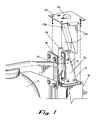
- FIGS. 1 a and 1 b show front and side views, respectively, of a pole according to an example form of the present invention, supporting a surveillance camera housing in an elevated position, and in broken lines showing a surveillance camera housing in a lowered position.
- FIGS. 2 a – 2 d show alternate mounting embodiments of a pole according to example forms of the present invention.
- FIG. 3 shows a cross-sectional view of a portion of the pole of FIG. 1 , taken at section line 3 — 3 , according to an example form of the present invention.
- FIG. 4 shows another cross-sectional view of a portion of the pole of FIG. 1 , taken at section line 4 — 4 , according to an example form of the present invention.
- FIGS. 5 a and 5 b show an exploded perspective view and a top sectional view, respectively, of a carriage portion and elongate pole portion of the pole of FIG. 1 , according to an example form of the present invention.
- FIGS. 6 a and b show a perspective view and a side elevational view, respectively, of an upper portion of the pole of FIG. 1 , supporting a supported object in an elevated position.
- FIG. 7 is an exploded perspective view of the carriage of FIG. 1 being received within the pole, according to a preferred form of the present invention.
- FIG. 8 is an exploded perspective view showing details of drive portions of the pole of FIG. 1 , according to an example form of the present invention.
- FIG. 9 is an assembled perspective view of a base portion of the pole of FIG. 1 , according to a preferred form of the present invention, showing a flexible drive shaft portion extended out of the pole's interior.
- FIG. 10 shows a schematic diagram of a remote control panel of the present invention, according to an example form.
- FIG. 11 is a perspective view of an electrical connection subsystem portion of the pole according to an example form of the invention.
- FIG. 12 is another perspective view of the electrical connection subsystem portion of the pole shown in FIG. 11 .
- FIG. 13 is a detailed perspective view of the electrical connection subsystem portion of the pole shown in FIG. 11 .
- FIG. 14 is another perspective view of the electrical connection subsystem portion of the pole shown in FIG. 11 , shown as it is brought into engagement for electrical connection.
- FIG. 15 is a rear perspective view of the electrical connection subsystem portion of the pole shown in FIG. 11 .
- FIG. 16 is a detailed perspective view of connector block portions of the electrical connection subsystem of the pole shown in FIG. 11 .
- FIGS. 17 a and 17 b are perspective views of an alternate embodiment of the pole of the present invention, including banner display elements, shown in lowered and raised positions, respectively.
- the present invention is a support pole 10 for raising and lowering one or more supported objects 12 , such as a surveillance camera, a light, an infrared illuminator, a flag, a banner, a sign, an antenna, weather monitoring equipment, and/or the like.
- the pole supports the object(s) 12 in an elevated position, shown in solid lines in FIGS. 1 a and 1 b , and permits the object(s) to be lowered to a lower position, shown in broken lines as element 12 ′, for maintenance, installation, service, etc.
- the support pole 10 includes a base plate 14 for mounting to a sidewalk or other surface, as with anchor bolts or other attachment means.
- the support pole 10 is mounted to a telephone emergency call station 16 .
- the support pole 10 is mounted to an existing pole such as a telephone pole or sign pole, preferably using mounting brackets 20 .
- the support pole 10 is mounted to a wall 18 or other structure.
- the support pole 10 is mounted to a transformer base 22 or other enclosure.
- the support pole 10 preferably comprises an elongate pole portion 30 , having a top 32 , a bottom 34 , and a channel 36 extending at least partly between the top and the bottom.
- the elongate pole portion 30 is preferably formed as an extrusion of a substantially rigid material such as aluminum, steel or plastic.
- the height of the elongate pole portion 30 is between about 10′ to about 20′, and most preferably about 16′. Of course, those skilled in the art will recognize that the height may be greater or less than the stated example dimensions, depending upon a particular intended application.
- the channel 36 will extend substantially the entire distance from the top 32 to the bottom 34 , thereby allowing the supported object to be raised and lowered along substantially the entire length of the elongate pole portion 30 .
- the support pole 10 is mounted to the top of a telephone call station 16 , it may be desirable that the supported object 12 be lowered to immediately adjacent the bottom 34 of the elongate pole portion 30 to permit a person standing on the ground or on a short ladder to reach the supported object.
- the channel 36 may extend along only a portion of the height of the elongate pole portion 30 , ending a distance from either the top 32 or the bottom 34 .
- the support pole 10 may be easier to service the supported object 12 at a position several feet above the ground than at ground level, in which instance the channel 36 need not extend all the way to the bottom 34 of the pole.
- the lower position of the supported object 12 will be within or just above the reach of a person of average height, whereby a short ladder is utilized to access the supported object.
- the elongate pole portion 30 is preferably a multi-sided or round extrusion having a partially hollow interior comprising one or more chambers extending substantially continuously along the height of the pole.
- the elongate pole portion 30 preferably comprises first and second side walls 40 , 42 , a back wall 44 , and a front wall 46 .
- Outer surfaces of the elongate pole portion 30 can optionally be provided with fluting or other decorative features, and/or informational indicia such as signage.
- One or more recesses are preferably formed in the outer surface of the pole 30 to receive changeable graphics for aesthetic, advertising or identification purposes.
- the front wall 46 preferably defines an opening or slot 48 extending at least partly along its length, defining the opening to the channel 36 .
- a gasket 50 preferably seals the slot 48 to prevent external elements such as rain, dust, insects and debris from entering into the interior chambers of the pole, but to allow passage of a carriage (described below) through the slot.
- the gasket 50 comprises cooperating first and second ribs formed of a resilient material such as rubber.
- the elongate pole portion 30 is preferably extruded to include keeper slots on opposed sides of the slot 48 to hold the gasket ribs.
- the gasket 50 can be affixed along the slot 48 by fasteners or adhesive.
- An endcap 52 is preferably attached at or integrally formed with the top 32 of the elongate pole portion 30 , as can be seen with reference to FIGS. 6 a , 6 b .
- a flashing light or other indicator can be attached at the top 32 of the elongate pole portion 30 , for example, to indicate the location of a telephone call station.
- the endcap 52 preferably comprises a drip ledge 54 overhanging the front wall 46 to prevent rain from running into the slot 48 .
- a lifting bracket 85 is preferably affixed to the pole 10 adjacent the top 32 .
- the lifting bracket 85 preferably comprises one or more openings or couplers for connection to a crane or other external lifting mechanism during installation, and/or for mounting a lightning rod or other component to the pole.
- One or more flanges 56 preferably provide structural bracing at the bottom 34 of the elongate pole portion 30 , as shown in FIGS. 1 and 3 .
- the bottom portion 34 of the pole preferably defines an interior chamber providing sufficient space to house any electronics and other equipment necessary for operation of the supported object.
- the support pole 10 preferably further comprises a carriage 70 , mounted for translational movement within the channel 36 , between a lower position and an elevated position.
- the carriage 70 preferably comprises a carriage body portion 72 defining a threaded bore 74 aligned generally coaxially with the elongate pole portion 30 , and generally parallel to the slot 48 of the channel 36 .
- the carriage 70 preferably further comprises one or more carriage guides 76 . Most preferably, first and second carriage guides 76 a , 76 b are mounted on opposite sides of the carriage body 72 .
- Each carriage guide 76 is preferably generally wedge-shaped when viewed from the side, in a viewing direction perpendicular to the axis of the bore 74 ; and is generally rectangular in cross-section when viewed end-on, in a viewing direction parallel to the axis of the bore 74 .
- Each carriage guide 76 preferably includes a beveled, inclined surface 78 , facing toward the top 32 of the elongate pole portion 30 .
- the surface 78 is preferably inclined at an acute angle ⁇ relative to the axis of the bore 74 ; and as seen best with reference to FIG. 4 , the surface 78 is preferably beveled at an angle ⁇ relative to the sides of the carriage guide 76 .
- the carriage preferably further comprises a mounting bracket 80 attached to the carriage body 72 by a connecting strut 82 .
- the connecting strut 82 preferably traverses the slot 48 along the length of the channel 36 , between and in sealing contact with the ribs of the gasket 50 .
- the connecting strut 82 preferably has rounded edges to prevent damage to the gasket 50 , and slopes downwardly from the carriage body 72 to the mounting bracket 80 , toward the bottom 34 of the elongate pole portion 30 , so that any rainwater contacting the strut 82 runs toward the exterior of the channel 36 .
- the mounting bracket 80 is preferably a generally flat metal plate, offset a small distance outside the channel 36 , and preferably does not physically contact the channel.
- the mounting bracket 80 preferably traverses immediately adjacent and external of the channel 36 , and is sized and shaped to substantially cover any opening formed between the gasket 50 and the strut 82 as the gasket parts to permit passage of the strut, thereby excluding any rain or debris from entering the interior of the channel.
- the mounting bracket 80 preferably defines one or more holes 84 for receiving bolts or other fasteners for attaching a supported object 12 to the carriage 70 .
- the holes 84 can be internally threaded or can be unthreaded through holes.
- the mounting bracket 80 preferably also defines a cable opening 86 for passing a cable connecting the supported object 12 to a remote location.
- the strut 82 preferably defines a conduit in communication with the cable opening 86 , and a cable clamp 88 is preferably mounted to the carriage 70 for securing the cable thereto.
- the elongate pole portion 30 preferably comprises one or more carriage guide tracks 90 extending lengthwise within the channel 36 .
- first and second guide tracks 90 a , 90 b are provided on opposite sides of the channel 36 , extending generally parallel to and adjacent the sidewalls 40 , 42 .
- Each track 90 a , 90 b is preferably configured to engage a respective carriage guide 76 a , 76 b , and constrain the carriage 70 to translational movement along the longitudinal axis of the channel 36 , thereby preventing any significant twisting, pivotal or transverse movement of the carriage.
- Each track 90 a , 90 b is preferably formed as part of the channel 36 by extruding an opposed pair of fins 92 along the interior front and back surfaces of the channel.
- the tracks 90 a , 90 b and the carriage guides 76 a , 76 b preferably comprise contacting surfaces presenting a low coefficient of friction, whereby the carriage 70 slides smoothly within the channel 36 .
- the tracks 90 a , 90 b are preferably formed of smooth aluminum, and the carriage guides 76 a , 76 b are preferably formed of ultra-high molecular weight (UHMW) polyethylene.
- UHMW ultra-high molecular weight
- the tracks 90 may be periodically lubricated if needed, and/or self-lubricating materials of construction can be utilized.
- the support pole 10 preferably further comprises a drive mechanism for imparting translational movement of the carriage 70 along the channel.
- the drive mechanism is substantially entirely housed within the elongate pole 30 , thereby protecting the drive mechanism from the elements, shielding personnel from injury by contact with moving parts, and improving the aesthetics of the overall device.
- the drive mechanism preferably comprises a threaded rod 100 rotationally mounted within the channel 36 , and extending between the elevated position and the lower position.
- the threaded rod is preferably between about 3 ⁇ 4′′ to 1 ′′ in diameter, and has an Acme single thread profile with a pitch of about six threads per inch (6 tpi).
- a support bracket or block 102 is preferably mounted in the base of the elongate pole portion 30 , adjacent or proximal the bottom 34 , for supporting the threaded rod 100 .
- a bearing 104 is preferably provided between the support bracket 102 and the threaded rod 100 to facilitate smooth rotation and constrain the bottom end of the rod in position, preventing any significant axial or transverse motion of the rod.
- a top plate 106 is preferably mounted at the top 32 of the elongate pole portion 30 , and defines an opening and/or bearing 108 constraining the top end of the rod 100 to rotational motion.
- the threaded rod 100 preferably engages the threaded bore 74 of the carriage 70 , whereby rotation of the rod 100 imparts translational movement upon the carriage 70 through the channel 36 .
- Rotation of the rod 100 in a first rotational direction e.g., clockwise
- rotation of the rod 100 in a second rotational direction e.g., counter-clockwise
- a second rotational direction e.g., counter-clockwise
- the threaded rod 100 is preferably connected to a detachable coupling for engagement of a drive tool 128 .
- the lower end of the rod 100 preferably comprises a first element of a detachable coupling 119 , adapted to cooperatively engage a second detachable coupling element of a flexible drive shaft 120 at a first end 121 of the flexible drive shaft.
- the flexible drive shaft 120 can be permanently coupled to the rod 100 .
- the second end 122 of the flexible drive shaft 120 is preferably releasably or permanently coupled to a drive tool 128 .
- the drive tool 128 can be manually driven, such as a wrench or a handcrank, or can be power driven, such as an electrical or pneumatic motor.
- the coupling is adapted to detachably couple with a portable cordless drillmotor.
- the flexible drive shaft 120 can be permanently or detachably coupled to the threaded rod 100 .
- the flexible drive shaft 120 has a length that permits the shaft to be housed within the interior of the base of the elongate pole portion 30 , beneath the support bracket 102 , when not in use; and to be accessed for use through an access opening 124 in the elongate pole portion 30 , whereby the coupling 122 can be withdrawn to a position external of the elongate pole portion 30 for connection to the drive tool.
- a cover plate 126 preferably covers the access opening 124 when the drive shaft 120 is not in use.
- the entire drive mechanism is housed within the pole.
- the pole can include an electrical drive motor mounted within its base portion and having an output drive coupled to the threaded rod 100 .
- the supported object 12 must be coupled, electronically or otherwise, to one or more remote devices and/or power sources.
- a supported surveillance camera is typically coupled electronically and/or optically to a remote power source and to remote monitoring and/or recording devices.
- the present invention optionally comprises a remote control panel 200 mounted to the base of the support pole 10 , which allows a user to verify the operation of a pan/tilt mechanism 201 of a surveillance camera housing carried as the supported object 12 in certain particular applications of the support pole. Provision of the remote control panel 200 permits testing of the pan/tilt mechanism 201 without the need for climbing a ladder or lowering the camera housing.
- the remote control panel 200 preferably comprises a video connector 202 for connection to an external video monitor.
- the remote control panel 200 preferably further comprises a control signal connector 204 for connection of an external controller 206 , such as a programmed computer, for selectively controlling the pan/tilt mechanism 201 .
- a power connector 208 for connection to an external power source 210 , and/or an internal power source (unshown) are also preferably provided.
- the remote control panel 200 is preferably connected to the communication and video lines that are used to normally control the pan/tilt mechanism 201 and transmit video signals, but does not affect the normal operation of the pan/tilt mechanism.
- Video output signals from the supported surveillance camera are transmitted via the video connector 202 to the connected video monitor as the controller 206 is operated to actuate the pan/tilt mechanism 201 .
- the remote control panel 200 preferably also comprises a control signal interface 212 for converting the electrical signal levels from the controller 206 to the electrical signal levels of the pan/tilt mechanism 201 .
- the remote control panel 200 preferably also comprises a control signal isolator 214 for isolating control wires from external equipment.
- the control signal isolator 214 can comprise means for manually isolating control wires from external equipment, or alternatively can comprise means for automatically isolating control wires from external equipment by detecting the presence of signals from the controller 206 .
- the support pole 10 preferably further comprises a stabilizer frame 140 , for bracing the threaded rod 100 to reduce vibration during rotation of the rod 100 .
- the stabilizer frame generally comprises an upper stabilizer block 142 , a lower stabilizer block 144 spaced a distance d from the upper plate, and one or more connecting members 146 extending between the upper and lower blocks.
- the distance d is preferably about 1 ⁇ 3 to 1 ⁇ 2 the length of the threaded rod 100 .
- Each of the upper and lower blocks 142 , 144 define an opening 148 , 150 having an inner diameter approximately equal to or slightly larger than the outer diameter of the threaded rod 100 .
- the upper and lower blocks 142 , 144 are preferably formed of UHMW polyethylene or other low-friction material.
- the stabilizer frame is mounted within the channel 36 , with the threaded rod 100 engaged within the openings 148 , 150 , and with the carriage 70 between the upper and lower blocks 142 , 144 .
- the upper and lower blocks 142 , 144 are preferably sized and shaped to slide in close registration within the channel 36 , for example, between the fins 92 forming the guide tracks 90 . In this manner, the upper and lower blocks provide bracing against lateral vibration of the rod 100 as the rod is rotated.
- the stabilizer frame is preferably carried along with the carriage 70 as the carriage traverses the channel 36 .
- the upper block 142 will brace the threaded rod near the midpoint of the rod's length when the carriage 70 is below the midpoint of the rod's length.
- the top of the carriage will contact the upper block 142 , and carry the stabilizer frame 140 upwardly through the channel.
- the lower block 144 of the stabilizer frame 140 will be positioned at about the midpoint of the threaded rod 100 .
- the threaded rod 100 is constrained against lateral deflection at its top and bottom ends by bearings 108 , 104 , respectively, in the absence of the bracing provided by the stabilizer frame, the rod would be prone to maximum vibratory deflection at or near its midpoint.
- the threaded rod is braced at or near the point of greatest susceptibility to vibration throughout the traverse of the carriage 70 .
- the support pole 10 of the present invention preferably further comprises at least one carriage lock, which will be described with particular reference to FIGS. 7 , 11 and 12 .
- a pair of carriage locks 170 a , 170 b are affixed within the guide tracks 90 a , 90 b , adjacent the top 32 of the elongate pole 30 , for example by attachment to the top plate 106 .
- the carriage locks 170 a , 170 b preferably comprise beveled, inclined surfaces supplementary to the beveled, inclined surfaces 78 of the carriage guides 76 a , 76 b .
- the beveled, inclined surfaces of the carriage guides 76 a , 76 b contact and engage the beveled, inclined surfaces of the carriage locks 170 a , 170 b to lock the carriage 70 in position and thereby prevent vibration and lateral movement of the supported object 12 in the elevated position.
- the cooperating beveled, inclined surfaces provide increased surface area of contact between the carriage locks 170 a , 170 b and the carriage guides 76 a , 76 b , and provide compressive forces therebetween in both an axial and a lateral direction, thereby providing more solid bracing against movement and vibration than would be provided by contact between non-inclined and/or non-beveled surfaces.
- the support pole 10 of the present invention preferably further comprises an electrical connection mechanism or subsystem for providing electrical power to a supported object 12 mounted on the carriage 70 , and/or for providing signal communication between the supported object to a remote device when the carriage is in its raised or elevated position.
- Electric power and/or signals is/are conducted to the upper portion of the elongate pole 30 by one or more fixed wires or electrical conductors extending through at least a portion of the length of the pole. For example, as shown in FIG.
- high-voltage conductors 230 a are fixedly mounted within a first cable duct 190 a
- low-voltage conductors 230 b are fixedly mounted within a second cable duct 190 b , which are preferably isolated and/or electrically shielded from one another, for example by arrangement of the cable ducts 190 a , 190 b on opposite sides of the channel 36 .
- the high-voltage conductor may carry, for example, 120V or 240V AC for powering a light source; and the low voltage conductor may carry, for example, 12V or 24V AC or DC for powering a surveillance camera, and/or signal voltage from a camera to a display monitor or the like.
- the fixed mounting of the conductors in the pole prevents possible damage to the conductors, such as compromising their insulation or detaching wire connections, which could result from movement of the conductors through the pole.
- the provision of separate cable ducts for high-voltage and low-voltage conductors reduces or eliminates potential interference with low-voltage signals that could result from proximity to high-voltage conductors, allows one set of conductors to be accessed without the need for de-energizing the other, and reduces any likelihood of confusion between conductors during installation or repair.
- the pole 10 of the present invention preferably further comprises at least one detachable electrical coupling configured for automatic connection of the fixed conductors 230 to equipment mounted on the carriage 70 when the carriage is brought into its raised position, and for automatic disconnection of the equipment from the conductors as the carriage is lowered out of its raised position.
- power and/or signals are communicated between the elevated equipment and one or more remote sources or monitoring stations during normal operation, but the equipment is de-energized when lowered for repair or inspection, thereby reducing risk of injury to repair personnel.
- This arrangement also eliminates the need for cable transport within the pole as the equipment is raised and lowered, thereby reducing complexity and cost of the equipment and eliminating the risk of damage to cables and associated equipment during transport; and also eliminates the need for manually connecting and disconnecting the equipment when the carriage is to be raised or lowered.
- the at least one fixed conductor(s) 230 are electrically connected to a first connector block 232 mounted at or adjacent the top end 32 of the elongate pole 30 , for example by attachment to the top plate 106 .
- a second connector block 238 is mounted to or integrally formed with the carriage 70 , and is configured for releasable engagement with the first connector block 232 to provide an electrically-conductive connection between the conductors 230 and the equipment mounted to the carriage when the carriage is in its raised position.
- the second connector block 238 is preferably affixed between the connector strut 82 and the bore 74 of carriage body 72 so as to not impede rotation of the rod 100 .
- the second connector block 238 is preferably in electrical connection with the supported object 12 via a cable or conductor extending through the connector strut 82 .
- the first and second connector blocks 232 , 238 can be interengaging couplings configured for direct engagement and disengagement therebetween, as for example in the form of male and female plug and socket electrical connectors.
- the first and second connector blocks 232 , 238 indirectly engage and disengage one another through an intermediate coupling 234 .
- the intermediate coupling 234 is mounted to or integrally formed with the upper stabilizing block 142 of the stabilizer frame 140 .
- the intermediate coupling 234 preferably comprises an upper electrical interface 234 a for releasable engagement and electrical connection with the first connector block 232 , and a lower electrical interface 234 b for releasable engagement and electrical connection with the second connector block 238 .
- the upper and lower electrical interfaces 234 a , 234 b are preferably connected by wires 236 or other conductors as shown in FIG. 16 .
- the intermediate coupling 234 and the first and second connector blocks 232 , 238 comprise Goldfish power connectors, Part Nos. GFSH109FIH and/or GFSH109MIH, commercially available from Positronic Industries of Springfield, Mo.
- the carriage 70 As shown in FIGS. 11 and 13 , as the carriage 70 is raised through the channel 36 toward its raised position (shown in solid lines in FIG. 1 ), the second connector block 238 is brought into engagement with the lower electrical interface 234 b .
- the carriage carries the stabilizer frame 140 upwardly as described above.
- the carriage 70 drives the upper electrical interface 234 a into connection with the first connector block 232 , as shown in FIG. 14 , thereby automatically completing the electrical connection between the conductor(s) 230 and the equipment mounted on the carriage 70 .
- the second connector block 238 Upon lowering of the carriage 70 from its raised position toward its lowered position, the second connector block 238 is disengaged from the lower electrical interface 234 b , and/or the upper electrical interface 234 a is disengaged from the first connector block 232 , as shown in FIG. 12 .
- the carriage contacts the lower stabilizer block 144 , and drives the stabilizer frame 140 downwardly as described above, completing the disengagement of the components, and automatically disconnecting the conductor(s) 230 from the equipment mounted on the carriage 70 .
- the present invention preferably further comprises one or more guidepins 240 (upper and a lower guidepins 240 a , 240 b are depicted) mounted to the upper stabilizer block 142 of the stabilizer frame 140 for engagement within one or more cooperating recesses 244 a , 244 b formed in or adjacent the first connector block 232 and the second connector block 238 respectively.
- the guidepins can project from one or both connector blocks and the recess(es) can be formed in the upper stabilizer block.
- the guidepins preferably are collapsible and biased outwardly by springs 242 to absorb impact forces and to slow the carriage as it enters the raised position.
- springs 242 can be provided in place of the springs 242 to slow the carriage and reduce impact.
- the lower guidepin 240 b is received within the recess 244 b on the second connector block 238 , and the recess 244 a in the first connector block 232 receives the upper guidepin 240 a , providing precise alignment of the electrical couplings as they are brought into connection.
- the springs 242 are compressed, thereby slowing the velocity of the carriage to prevent damage to the components and reduce noise.
- one of the high or low voltage conductors is fixedly mounted to the pole and coupled and de-coupled by way of a detachable electrical coupling means as described above; and the other of the high or low voltage conductors travels up and down through the pole as the carriage is raised and lowered, as for example over a pulley transport mechanism in the manner shown and described by U.S. Pat. No. 6,447,150 and or International Publication WO 01/75849 A2, both incorporated by reference herein.
- FIGS. 17 a and 17 b depict a further embodiment of the pole of the present invention, comprising a banner display system, shown in a lowered and a raised configuration, respectively.
- One or more lower banner posts 220 are preferably mounted to the pole between the top 32 and the bottom 34 .
- Two lower banner posts 220 are depicted, permitting a pair of banners to be displayed simultaneously.
- the lower banner posts 220 are optionally detachably mounted to the pole to permit selective positioning depending upon the size of the banner to be displayed.
- the lower banner posts 220 are permanently mounted in a fixed position on the pole.
- One or more upper banner posts 222 are preferably mounted to the carriage 70 , whereby the upper banner posts are raised and lowered along with the carriage.
- the mounting bracket 80 is preferably modified to include one or more side flanges for mounting the upper banner post(s) 222 .
- the bottom of a banner 224 is secured to the lower banner posts 220
- the top of the banner is secured to the upper banner posts 222 .
- the carriage 70 and attached upper banner post(s) 222 are lowered to install and remove the banner(s) 224 , and raised to display the banner(s).
- one or more supported object such as a surveillance camera, a light, etc.
- the carriage 70 is preferably lowered to the lower position shown in broken lines in FIG. 1 for installation and maintenance of the supported object.
- the drive mechanism is actuated to rotationally drive the threaded rod 100 , thereby moving the carriage 70 upwardly through the channel 36 , into the elevated position shown in solid lines in FIG. 1 .
- the carriage locks 170 engage the carriage guides 76 to prevent vibration of the supported object.
- an electrical connection is automatically made between the supported object(s) mounted to the carriage and one or more fixed conductor(s) extending through the pole, by releasably engaging one or more electrical coupling(s) mounted to the carriage with one or more electrical coupling(s) mounted at the top of the pole and connected to the fixed conductors.
- the supported object is then used according to standard practice. For example, a supported surveillance camera obtains images from a monitored area surrounding the support pole 10 , and sends signals to remote monitoring and/or recording devices. To service the supported object, the drive means is actuated in a reverse direction to lower the carriage 70 .
- the electrical connection between the supported object(s) mounted to the carriage and the one or more fixed conductor(s) extending through the pole is automatically disconnected by disengagement of the electrical couplings.
- the supported object is raised back into the elevated position as described above.
Abstract
Description
Claims (29)
Priority Applications (1)
| Application Number | Priority Date | Filing Date | Title |
|---|---|---|---|
| US10/714,810 US7004043B2 (en) | 2000-04-04 | 2003-11-17 | Elevated support pole with automatic electrical connection and disconnection |
Applications Claiming Priority (5)
| Application Number | Priority Date | Filing Date | Title |
|---|---|---|---|
| US19491900P | 2000-04-04 | 2000-04-04 | |
| US09/566,350 US6447150B1 (en) | 2000-04-04 | 2000-05-08 | Pole with lifting mount |
| PCT/US2001/010618 WO2001075849A2 (en) | 2000-04-04 | 2001-04-03 | Pole with lifting mount for supporting object |
| US10/256,725 US6665968B2 (en) | 2000-04-04 | 2002-09-27 | Pole with lifting mount and banner display |
| US10/714,810 US7004043B2 (en) | 2000-04-04 | 2003-11-17 | Elevated support pole with automatic electrical connection and disconnection |
Related Parent Applications (1)
| Application Number | Title | Priority Date | Filing Date |
|---|---|---|---|
| US10/256,725 Continuation-In-Part US6665968B2 (en) | 2000-04-04 | 2002-09-27 | Pole with lifting mount and banner display |
Publications (2)
| Publication Number | Publication Date |
|---|---|
| US20040139812A1 US20040139812A1 (en) | 2004-07-22 |
| US7004043B2 true US7004043B2 (en) | 2006-02-28 |
Family
ID=32718966
Family Applications (1)
| Application Number | Title | Priority Date | Filing Date |
|---|---|---|---|
| US10/714,810 Expired - Lifetime US7004043B2 (en) | 2000-04-04 | 2003-11-17 | Elevated support pole with automatic electrical connection and disconnection |
Country Status (1)
| Country | Link |
|---|---|
| US (1) | US7004043B2 (en) |
Cited By (16)
| Publication number | Priority date | Publication date | Assignee | Title |
|---|---|---|---|---|
| WO2006023740A2 (en) * | 2004-08-18 | 2006-03-02 | Kerem Tepecik | Vertical track device for raising and lowering fixtures thereon |
| US7432875B1 (en) * | 2004-09-07 | 2008-10-07 | Sergi Paul D | System for attaching the mast of an antenna to a support post |
| US20100051767A1 (en) * | 2008-09-04 | 2010-03-04 | Bulent Erel | Elevated support system |
| US20100118556A1 (en) * | 2008-11-12 | 2010-05-13 | Long Charles R | Exterior Lighting System |
| US20100140421A1 (en) * | 2007-06-05 | 2010-06-10 | Bong-Joo Lee | Up-and-down apparatus of the adapter |
| US20110095147A1 (en) * | 2009-10-22 | 2011-04-28 | Mensching Herman E | Apparatus for adjusting the length of a boat lift leg |
| US20110298686A1 (en) * | 2010-06-03 | 2011-12-08 | Qwest Communications International Inc. | Antenna installation apparatus and method |
| US8130168B1 (en) | 2009-10-13 | 2012-03-06 | Pds Electronics, Inc. | Apparatus for raising and lowering an antena |
| US8454208B2 (en) * | 2011-05-12 | 2013-06-04 | Catapult Engineering, Llc | Retractable energy conserving solar or other powered landscape light including method of replacing retractable landscape light |
| US8516752B2 (en) * | 2010-06-18 | 2013-08-27 | Valmont Industries, Inc. | Support pole having a track |
| US8686919B1 (en) | 2011-06-06 | 2014-04-01 | Paul D. Sergi | Apparatus for allowing pivotal movement of an antenna mast relative to its support post |
| US8991122B2 (en) | 2012-06-15 | 2015-03-31 | Jay Abbey | Precast light pole foundation |
| US9054810B2 (en) | 2013-02-11 | 2015-06-09 | Centurylink Intellectual Property Llc | Distributed outdoor network apparatus and methods |
| US9553350B2 (en) | 2015-05-14 | 2017-01-24 | Micro Wireless Solutions, Corp. | Antenna mount assembly |
| US9605838B2 (en) * | 2015-06-11 | 2017-03-28 | Kyung Hwan Kim | Safe lighting system using wall mounted lift |
| US10851936B1 (en) * | 2018-05-16 | 2020-12-01 | Glenn Joseph Bronson | Camera mount plate and module access slide for poles used for roadside electronic systems |
Families Citing this family (22)
| Publication number | Priority date | Publication date | Assignee | Title |
|---|---|---|---|---|
| US20040179093A1 (en) * | 2003-03-04 | 2004-09-16 | Sabit Inan | Remote camera system |
| TWI246954B (en) * | 2004-10-26 | 2006-01-11 | Global Ind Holdings Ltd | Tool box hanging base |
| US7165870B2 (en) * | 2005-01-19 | 2007-01-23 | Mckenney Jerry D | Vibration dampening device for light fixtures |
| AT506355B1 (en) * | 2008-01-29 | 2009-11-15 | Alpine En Oesterreich Gmbh | DEVICE FOR HEIGHT-ADJUSTABLE MOUNTING OF LIGHTING BODIES TO UPPER-LINKING MUSTS |
| US8074955B2 (en) * | 2008-07-07 | 2011-12-13 | Cooper Technologies Company | Method and apparatus for improving the strength of a utility pole |
| US8448906B2 (en) * | 2008-08-21 | 2013-05-28 | Knoll, Inc. | Support apparatus |
| CN103256460A (en) * | 2012-02-16 | 2013-08-21 | 纬创资通股份有限公司 | Powered slide rail assembly |
| DK2818922T3 (en) | 2013-06-27 | 2016-07-25 | Vitronic Dr -Ing Stein Bildverarbeitungssysteme Gmbh | Traffic monitoring device |
| WO2016070239A1 (en) * | 2014-11-07 | 2016-05-12 | Stockl Christian | Pole for a banner |
| USD841073S1 (en) | 2015-06-04 | 2019-02-19 | Parabit Systems, Inc. | Surveillance camera enclosure |
| USD833504S1 (en) | 2015-12-30 | 2018-11-13 | Parabit Systems, Inc. | Surveillance camera enclosure |
| US9983462B2 (en) * | 2015-12-30 | 2018-05-29 | Parabit Systems, Inc. | Adjustable camera enclosure |
| US10761409B2 (en) | 2018-01-12 | 2020-09-01 | Parabit Systems, Inc. | Surveillance camera enclosure |
| USD887477S1 (en) | 2018-01-12 | 2020-06-16 | Parabit Systems, Inc. | Surveillance camera enclosure |
| USD863401S1 (en) | 2018-05-16 | 2019-10-15 | Parabit Systems, Inc. | Surveillance camera enclosure |
| USD870791S1 (en) | 2018-06-26 | 2019-12-24 | Parabit Systems, Inc. | Surveillance camera enclosure |
| USD896864S1 (en) | 2018-12-26 | 2020-09-22 | Parabit Systems, Inc. | Surveillance camera enclosure |
| USD896865S1 (en) | 2018-12-26 | 2020-09-22 | Parabit Systems, Inc. | Surveillance camera enclosure |
| EP3948064A2 (en) * | 2019-04-02 | 2022-02-09 | American Sterilizer Company | Lighting assemblies for medical device suspension system |
| CN112460518B (en) * | 2020-11-19 | 2022-06-24 | 东莞市景润装饰有限公司 | Intelligent installation system and replacement method for indoor lighting system |
| USD992635S1 (en) | 2021-08-02 | 2023-07-18 | Parabit Systems, Inc. | Surveillance camera enclosure |
| BE1030085B1 (en) * | 2021-12-23 | 2023-07-24 | Trafiroad Nv | Mounting system for an ANPR camera on a pole |
Citations (38)
| Publication number | Priority date | Publication date | Assignee | Title |
|---|---|---|---|---|
| US2738492A (en) | 1952-02-18 | 1956-03-13 | M & A Mfg Co | Signal light for automotive vehicles |
| US2908408A (en) | 1958-02-12 | 1959-10-13 | Jr Maurice T Reed | Screw driven tailgate loader |
| US3610584A (en) | 1969-01-21 | 1971-10-05 | Pfaff & Kendall | Lowering device mechanism |
| US3822051A (en) | 1971-08-13 | 1974-07-02 | A Karapita | Telescopic support |
| US4025782A (en) | 1976-02-24 | 1977-05-24 | Lca Corporation | Pole and device for raising and lowering lighting fixtures thereon |
| US4051525A (en) | 1976-05-17 | 1977-09-27 | Anderson Safeway Guard Rail Corporation | Raisable and lowerable surveillance camera assembly |
| US4149230A (en) * | 1977-09-22 | 1979-04-10 | Gar Design Research, Inc. | Visual latching condition indicating system for tall pole carrier assembly |
| US4162708A (en) * | 1975-02-03 | 1979-07-31 | Dakota Electron, Inc. | Tool carrying vehicle with laser control apparatus |
| US4173268A (en) | 1976-10-29 | 1979-11-06 | Hans Nussbaum | Hoist mechanism |
| US4198022A (en) | 1978-03-10 | 1980-04-15 | Johns-Manville Corporation | Power cable guide for high-mast luminaire raising and lowering system |
| DE3101202A1 (en) | 1981-01-16 | 1982-11-11 | Werner 7180 Crailsheim Neumayer | Retaining mast for light systems, traffic-light systems and signalling systems |
| US4537083A (en) | 1981-10-23 | 1985-08-27 | Imasco-Cdc Research Foundation | Device for imparting continuous passive motion to human joints |
| US4593883A (en) | 1984-12-10 | 1986-06-10 | Nelson Richard P | Portable lifting, loading and transporting device |
| US4618886A (en) | 1985-06-19 | 1986-10-21 | Quick-Set Incorporated | Surveillance camera mount |
| US4656569A (en) | 1985-10-22 | 1987-04-07 | Hugh Buskell | Elevating apparatus particularly for the canopy of a lamp standard |
| US4658212A (en) * | 1983-12-27 | 1987-04-14 | Tokai Electric Wire Company Limited | Connector terminal examination device |
| US4717353A (en) * | 1987-01-21 | 1988-01-05 | Mcdermott Incorporated | Docking head and plate |
| US4878160A (en) * | 1988-03-11 | 1989-10-31 | Reneau George W | Outdoor lightpole |
| US4974134A (en) | 1989-11-29 | 1990-11-27 | Bourne Steven M | Illumination device having underground storage position |
| USD314501S (en) | 1988-01-11 | 1991-02-12 | Pagano Raymond V | Video camera bracket |
| US5224675A (en) | 1991-11-01 | 1993-07-06 | Pelco | Mounting apparatus |
| US5255882A (en) | 1990-06-19 | 1993-10-26 | Diehl Gmbh & Co. | Setting device with a nut controllable by a spindle |
| WO1994016267A1 (en) | 1993-01-08 | 1994-07-21 | Arnesson Per O | A lifting device for the controlled vertical transfer of objects |
| US5349878A (en) | 1991-09-05 | 1994-09-27 | Rockwell International Corporation | Horizontal seat position adjuster |
| US5398026A (en) | 1992-04-03 | 1995-03-14 | Handsaker; Jerrold L. | Retractable boat signaling means |
| US5406327A (en) | 1992-11-30 | 1995-04-11 | Dessins Et Techniques De L'ingenierie | Tensioning device for the power-supply and coaxial cables of a camera which is moved in a video surveillance tunnel |
| US5429519A (en) * | 1992-09-03 | 1995-07-04 | Sumitomo Wiring Systems, Ltd. | Connector examining device |
| US5550727A (en) | 1995-07-24 | 1996-08-27 | Fenyvesy; Thomas P. | Outdoor illuminator |
| US5647758A (en) * | 1995-02-23 | 1997-07-15 | Molex Incorporated | Electrical connector assembly with biased guide means |
| FR2752805A1 (en) | 1996-09-04 | 1998-03-06 | Timeat | Road traffic surveillance video camera maintenance system |
| US5743324A (en) * | 1994-06-10 | 1998-04-28 | Rotelec | Disconnectable electrical connection system for a moving assembly |
| US5887841A (en) | 1996-06-13 | 1999-03-30 | Newberg; Timothy P. | Pole support for use in mast assembly to adjust sail tension |
| US5975726A (en) | 1997-09-19 | 1999-11-02 | Quality Lighting | High mast lighting system |
| US6081240A (en) | 1998-02-19 | 2000-06-27 | Hemmingsen, Ii; Robert J. | Satellite antenna alignment device |
| US6354749B1 (en) | 1998-09-09 | 2002-03-12 | Videolarm, Inc. | Housing for surveillance camera |
| US6375369B1 (en) | 1999-04-22 | 2002-04-23 | Videolarm, Inc. | Housing for a surveillance camera |
| US6447150B1 (en) | 2000-04-04 | 2002-09-10 | Videolarm, Inc. | Pole with lifting mount |
| FR2824624A1 (en) | 2001-05-11 | 2002-11-15 | Tahar Lahdiri | Electric lighting column with motorized light bulb changing, use mobile bulb support running on column rack and pinion system transporting bulb from low level into high energized position |
Family Cites Families (4)
| Publication number | Priority date | Publication date | Assignee | Title |
|---|---|---|---|---|
| US307759A (en) * | 1884-11-11 | Walter glass | ||
| US314501A (en) * | 1885-03-24 | Churn | ||
| US4890713A (en) * | 1988-07-22 | 1990-01-02 | Pagano Raymond V | Pan and tilt motor for surveillance camera |
| DE4008340A1 (en) * | 1990-03-15 | 1991-09-26 | Hartig E Videor Tech | PROTECTIVE HOUSING FOR OPTICAL DEVICES |
-
2003
- 2003-11-17 US US10/714,810 patent/US7004043B2/en not_active Expired - Lifetime
Patent Citations (38)
| Publication number | Priority date | Publication date | Assignee | Title |
|---|---|---|---|---|
| US2738492A (en) | 1952-02-18 | 1956-03-13 | M & A Mfg Co | Signal light for automotive vehicles |
| US2908408A (en) | 1958-02-12 | 1959-10-13 | Jr Maurice T Reed | Screw driven tailgate loader |
| US3610584A (en) | 1969-01-21 | 1971-10-05 | Pfaff & Kendall | Lowering device mechanism |
| US3822051A (en) | 1971-08-13 | 1974-07-02 | A Karapita | Telescopic support |
| US4162708A (en) * | 1975-02-03 | 1979-07-31 | Dakota Electron, Inc. | Tool carrying vehicle with laser control apparatus |
| US4025782A (en) | 1976-02-24 | 1977-05-24 | Lca Corporation | Pole and device for raising and lowering lighting fixtures thereon |
| US4051525A (en) | 1976-05-17 | 1977-09-27 | Anderson Safeway Guard Rail Corporation | Raisable and lowerable surveillance camera assembly |
| US4173268A (en) | 1976-10-29 | 1979-11-06 | Hans Nussbaum | Hoist mechanism |
| US4149230A (en) * | 1977-09-22 | 1979-04-10 | Gar Design Research, Inc. | Visual latching condition indicating system for tall pole carrier assembly |
| US4198022A (en) | 1978-03-10 | 1980-04-15 | Johns-Manville Corporation | Power cable guide for high-mast luminaire raising and lowering system |
| DE3101202A1 (en) | 1981-01-16 | 1982-11-11 | Werner 7180 Crailsheim Neumayer | Retaining mast for light systems, traffic-light systems and signalling systems |
| US4537083A (en) | 1981-10-23 | 1985-08-27 | Imasco-Cdc Research Foundation | Device for imparting continuous passive motion to human joints |
| US4658212A (en) * | 1983-12-27 | 1987-04-14 | Tokai Electric Wire Company Limited | Connector terminal examination device |
| US4593883A (en) | 1984-12-10 | 1986-06-10 | Nelson Richard P | Portable lifting, loading and transporting device |
| US4618886A (en) | 1985-06-19 | 1986-10-21 | Quick-Set Incorporated | Surveillance camera mount |
| US4656569A (en) | 1985-10-22 | 1987-04-07 | Hugh Buskell | Elevating apparatus particularly for the canopy of a lamp standard |
| US4717353A (en) * | 1987-01-21 | 1988-01-05 | Mcdermott Incorporated | Docking head and plate |
| USD314501S (en) | 1988-01-11 | 1991-02-12 | Pagano Raymond V | Video camera bracket |
| US4878160A (en) * | 1988-03-11 | 1989-10-31 | Reneau George W | Outdoor lightpole |
| US4974134A (en) | 1989-11-29 | 1990-11-27 | Bourne Steven M | Illumination device having underground storage position |
| US5255882A (en) | 1990-06-19 | 1993-10-26 | Diehl Gmbh & Co. | Setting device with a nut controllable by a spindle |
| US5349878A (en) | 1991-09-05 | 1994-09-27 | Rockwell International Corporation | Horizontal seat position adjuster |
| US5224675A (en) | 1991-11-01 | 1993-07-06 | Pelco | Mounting apparatus |
| US5398026A (en) | 1992-04-03 | 1995-03-14 | Handsaker; Jerrold L. | Retractable boat signaling means |
| US5429519A (en) * | 1992-09-03 | 1995-07-04 | Sumitomo Wiring Systems, Ltd. | Connector examining device |
| US5406327A (en) | 1992-11-30 | 1995-04-11 | Dessins Et Techniques De L'ingenierie | Tensioning device for the power-supply and coaxial cables of a camera which is moved in a video surveillance tunnel |
| WO1994016267A1 (en) | 1993-01-08 | 1994-07-21 | Arnesson Per O | A lifting device for the controlled vertical transfer of objects |
| US5743324A (en) * | 1994-06-10 | 1998-04-28 | Rotelec | Disconnectable electrical connection system for a moving assembly |
| US5647758A (en) * | 1995-02-23 | 1997-07-15 | Molex Incorporated | Electrical connector assembly with biased guide means |
| US5550727A (en) | 1995-07-24 | 1996-08-27 | Fenyvesy; Thomas P. | Outdoor illuminator |
| US5887841A (en) | 1996-06-13 | 1999-03-30 | Newberg; Timothy P. | Pole support for use in mast assembly to adjust sail tension |
| FR2752805A1 (en) | 1996-09-04 | 1998-03-06 | Timeat | Road traffic surveillance video camera maintenance system |
| US5975726A (en) | 1997-09-19 | 1999-11-02 | Quality Lighting | High mast lighting system |
| US6081240A (en) | 1998-02-19 | 2000-06-27 | Hemmingsen, Ii; Robert J. | Satellite antenna alignment device |
| US6354749B1 (en) | 1998-09-09 | 2002-03-12 | Videolarm, Inc. | Housing for surveillance camera |
| US6375369B1 (en) | 1999-04-22 | 2002-04-23 | Videolarm, Inc. | Housing for a surveillance camera |
| US6447150B1 (en) | 2000-04-04 | 2002-09-10 | Videolarm, Inc. | Pole with lifting mount |
| FR2824624A1 (en) | 2001-05-11 | 2002-11-15 | Tahar Lahdiri | Electric lighting column with motorized light bulb changing, use mobile bulb support running on column rack and pinion system transporting bulb from low level into high energized position |
Cited By (31)
| Publication number | Priority date | Publication date | Assignee | Title |
|---|---|---|---|---|
| US20060042879A1 (en) * | 2004-08-18 | 2006-03-02 | Kerem Tepecik | Vertical track device for raising and lowering fixtures thereon |
| WO2006023740A3 (en) * | 2004-08-18 | 2007-11-29 | Kerem Tepecik | Vertical track device for raising and lowering fixtures thereon |
| WO2006023740A2 (en) * | 2004-08-18 | 2006-03-02 | Kerem Tepecik | Vertical track device for raising and lowering fixtures thereon |
| US7432875B1 (en) * | 2004-09-07 | 2008-10-07 | Sergi Paul D | System for attaching the mast of an antenna to a support post |
| US20100140421A1 (en) * | 2007-06-05 | 2010-06-10 | Bong-Joo Lee | Up-and-down apparatus of the adapter |
| US8403302B2 (en) | 2008-09-04 | 2013-03-26 | Videolarm, Inc. | Elevated support system |
| US20100051767A1 (en) * | 2008-09-04 | 2010-03-04 | Bulent Erel | Elevated support system |
| US20100118556A1 (en) * | 2008-11-12 | 2010-05-13 | Long Charles R | Exterior Lighting System |
| US8328397B2 (en) * | 2008-11-12 | 2012-12-11 | Long Charles R | Exterior lighting system |
| US8130168B1 (en) | 2009-10-13 | 2012-03-06 | Pds Electronics, Inc. | Apparatus for raising and lowering an antena |
| US20110095147A1 (en) * | 2009-10-22 | 2011-04-28 | Mensching Herman E | Apparatus for adjusting the length of a boat lift leg |
| US8282053B2 (en) * | 2009-10-22 | 2012-10-09 | Mensching Herman E | Apparatus for adjusting the length of a boat lift leg |
| US20110298686A1 (en) * | 2010-06-03 | 2011-12-08 | Qwest Communications International Inc. | Antenna installation apparatus and method |
| US8373612B2 (en) * | 2010-06-03 | 2013-02-12 | Qwest Communications International Inc. | Antenna installation apparatus and method |
| US8836607B2 (en) * | 2010-06-03 | 2014-09-16 | Centurylink Intellectual Property Llc | Antenna installation apparatus and method |
| US8599100B2 (en) | 2010-06-03 | 2013-12-03 | Centurylink Intellectual Property Llc | Antenna installation apparatus and method |
| US10181635B2 (en) | 2010-06-03 | 2019-01-15 | Centurylink Intellectual Property Llc | Antenna installation apparatus and method |
| US8516752B2 (en) * | 2010-06-18 | 2013-08-27 | Valmont Industries, Inc. | Support pole having a track |
| US8454208B2 (en) * | 2011-05-12 | 2013-06-04 | Catapult Engineering, Llc | Retractable energy conserving solar or other powered landscape light including method of replacing retractable landscape light |
| US8686919B1 (en) | 2011-06-06 | 2014-04-01 | Paul D. Sergi | Apparatus for allowing pivotal movement of an antenna mast relative to its support post |
| US8991122B2 (en) | 2012-06-15 | 2015-03-31 | Jay Abbey | Precast light pole foundation |
| US9624640B2 (en) | 2012-06-15 | 2017-04-18 | Jay Abbey | Precast light pole foundation |
| US9054810B2 (en) | 2013-02-11 | 2015-06-09 | Centurylink Intellectual Property Llc | Distributed outdoor network apparatus and methods |
| US9438344B2 (en) | 2013-02-11 | 2016-09-06 | Centurylink Intellectual Property Llc | Distributed outdoor network apparatus and methods |
| US9843393B2 (en) | 2013-02-11 | 2017-12-12 | Centurylink Intellectual Property Llc | Distributed outdoor network apparatus and methods |
| US10374712B2 (en) | 2013-02-11 | 2019-08-06 | Centurylink Intellectual Property Llc | Distributed outdoor network apparatus and methods |
| US9553350B2 (en) | 2015-05-14 | 2017-01-24 | Micro Wireless Solutions, Corp. | Antenna mount assembly |
| US10044091B2 (en) | 2015-05-14 | 2018-08-07 | Micro Wireless Solutions, Corp. | Antenna equipment mount |
| US9605838B2 (en) * | 2015-06-11 | 2017-03-28 | Kyung Hwan Kim | Safe lighting system using wall mounted lift |
| US10851936B1 (en) * | 2018-05-16 | 2020-12-01 | Glenn Joseph Bronson | Camera mount plate and module access slide for poles used for roadside electronic systems |
| US11209120B1 (en) | 2018-05-16 | 2021-12-28 | Glenn Joseph Bronson | Camera mount plate and module access slide for poles used for roadside electronic systems |
Also Published As
| Publication number | Publication date |
|---|---|
| US20040139812A1 (en) | 2004-07-22 |
Similar Documents
| Publication | Publication Date | Title |
|---|---|---|
| US7004043B2 (en) | Elevated support pole with automatic electrical connection and disconnection | |
| US6665968B2 (en) | Pole with lifting mount and banner display | |
| US5570546A (en) | System for raising and lowering communications equipment | |
| US4051525A (en) | Raisable and lowerable surveillance camera assembly | |
| US6349503B1 (en) | Fluid powered barrier system | |
| EP1967784A2 (en) | Improved line and rope system and method for movement of an object through three-dimensional space | |
| WO2006023740A2 (en) | Vertical track device for raising and lowering fixtures thereon | |
| US11209120B1 (en) | Camera mount plate and module access slide for poles used for roadside electronic systems | |
| US20040194361A1 (en) | Up-and-down display sign | |
| US20050188571A1 (en) | Elevated sign system with lowering mechanism to enable ground level servicing | |
| KR101681036B1 (en) | buried distribution board for street lamps | |
| WO2005059856A1 (en) | Elevated support pole with automatic electrical connection and disconnection | |
| US7189047B2 (en) | Apparatus for moving a battery | |
| CN217233021U (en) | A security fence for building engineering construction management | |
| CN2323530Y (en) | Telescopic type electric lifting frame for TV set | |
| US20040261303A1 (en) | Display apparatus | |
| KR102613821B1 (en) | Frame for rail installation | |
| CN116768066B (en) | Bridge crane remote centralized control system | |
| CN219346029U (en) | Monitoring equipment fixing device | |
| CN218122707U (en) | Three-roller gate with recognition function | |
| KR102638944B1 (en) | Camera assembly auto-lift device for rotating CCTV camera and fixed surveillance cameras | |
| CN211949759U (en) | Sliding safety bracket for building construction | |
| CN218032154U (en) | Wall-mounted upward pull type LED display screen suitable for stand | |
| CN210072088U (en) | Outdoor rain-proof safety inspection door of preventing wind | |
| CN116163249A (en) | Electric lifting type road traffic limiting equipment |
Legal Events
| Date | Code | Title | Description |
|---|---|---|---|
| AS | Assignment |
Owner name: VIDEOLARM, INC., GEORGIA Free format text: ASSIGNMENT OF ASSIGNORS INTEREST;ASSIGNOR:JEN, CHUNG-HUA;REEL/FRAME:014992/0064 Effective date: 20040123 Owner name: VIDEOLARM, INC., GEORGIA Free format text: ASSIGNMENT OF ASSIGNORS INTEREST;ASSIGNORS:EREL, BULENT;PAGANO, RAYMOND V.;PFAFFENBERGER, JAMES L., II;AND OTHERS;REEL/FRAME:014991/0207 Effective date: 20040216 |
|
| STCF | Information on status: patent grant |
Free format text: PATENTED CASE |
|
| FPAY | Fee payment |
Year of fee payment: 4 |
|
| AS | Assignment |
Owner name: HSBC BANK USA, NATIONAL ASSOCIATION, NEW YORK Free format text: NOTICE OF SECURITY INTEREST IN PATENTS AND PATENT APPLICATIONS;ASSIGNOR:VIDEOLARM, INC.;REEL/FRAME:026003/0300 Effective date: 20110318 |
|
| FEPP | Fee payment procedure |
Free format text: PAT HOLDER NO LONGER CLAIMS SMALL ENTITY STATUS, ENTITY STATUS SET TO UNDISCOUNTED (ORIGINAL EVENT CODE: STOL); ENTITY STATUS OF PATENT OWNER: LARGE ENTITY |
|
| FPAY | Fee payment |
Year of fee payment: 8 |
|
| AS | Assignment |
Owner name: MOOG INC., NEW YORK Free format text: MERGER;ASSIGNOR:VIDEOLARM, INC.;REEL/FRAME:031892/0464 Effective date: 20131205 |
|
| FEPP | Fee payment procedure |
Free format text: 11.5 YR SURCHARGE- LATE PMT W/IN 6 MO, LARGE ENTITY (ORIGINAL EVENT CODE: M1556) |
|
| MAFP | Maintenance fee payment |
Free format text: PAYMENT OF MAINTENANCE FEE, 12TH YEAR, LARGE ENTITY (ORIGINAL EVENT CODE: M1553) Year of fee payment: 12 |