US6996264B2 - Indentation hardness test system - Google Patents
Indentation hardness test system Download PDFInfo
- Publication number
- US6996264B2 US6996264B2 US10/679,823 US67982303A US6996264B2 US 6996264 B2 US6996264 B2 US 6996264B2 US 67982303 A US67982303 A US 67982303A US 6996264 B2 US6996264 B2 US 6996264B2
- Authority
- US
- United States
- Prior art keywords
- composite image
- processor
- real
- time images
- stage
- Prior art date
- Legal status (The legal status is an assumption and is not a legal conclusion. Google has not performed a legal analysis and makes no representation as to the accuracy of the status listed.)
- Expired - Lifetime, expires
Links
- 238000007541 indentation hardness test Methods 0.000 title claims abstract description 15
- 239000002131 composite material Substances 0.000 claims abstract description 61
- 238000007373 indentation Methods 0.000 claims description 21
- 238000000034 method Methods 0.000 claims description 10
- 238000010586 diagram Methods 0.000 claims description 8
- 238000012360 testing method Methods 0.000 description 16
- 238000004590 computer program Methods 0.000 description 7
- 239000000463 material Substances 0.000 description 6
- 238000012546 transfer Methods 0.000 description 5
- 230000008901 benefit Effects 0.000 description 2
- 230000001276 controlling effect Effects 0.000 description 2
- 230000002596 correlated effect Effects 0.000 description 2
- 229910003460 diamond Inorganic materials 0.000 description 2
- 239000010432 diamond Substances 0.000 description 2
- 238000007542 hardness measurement Methods 0.000 description 2
- 238000012986 modification Methods 0.000 description 2
- 230000004048 modification Effects 0.000 description 2
- 230000008569 process Effects 0.000 description 2
- 238000012545 processing Methods 0.000 description 2
- KXGFMDJXCMQABM-UHFFFAOYSA-N 2-methoxy-6-methylphenol Chemical compound [CH]OC1=CC=CC([CH])=C1O KXGFMDJXCMQABM-UHFFFAOYSA-N 0.000 description 1
- 238000012937 correction Methods 0.000 description 1
- 238000013461 design Methods 0.000 description 1
- 238000011156 evaluation Methods 0.000 description 1
- 230000006870 function Effects 0.000 description 1
- 238000004519 manufacturing process Methods 0.000 description 1
- 230000007246 mechanism Effects 0.000 description 1
- 229910052751 metal Inorganic materials 0.000 description 1
- 239000002184 metal Substances 0.000 description 1
- 150000002739 metals Chemical class 0.000 description 1
- 238000012544 monitoring process Methods 0.000 description 1
- 239000005011 phenolic resin Substances 0.000 description 1
- 229920001568 phenolic resin Polymers 0.000 description 1
- 238000003908 quality control method Methods 0.000 description 1
- 238000012827 research and development Methods 0.000 description 1
- 238000012552 review Methods 0.000 description 1
Images


Classifications
-
- G—PHYSICS
- G01—MEASURING; TESTING
- G01N—INVESTIGATING OR ANALYSING MATERIALS BY DETERMINING THEIR CHEMICAL OR PHYSICAL PROPERTIES
- G01N3/00—Investigating strength properties of solid materials by application of mechanical stress
- G01N3/40—Investigating hardness or rebound hardness
- G01N3/48—Investigating hardness or rebound hardness by performing impressions under impulsive load by indentors, e.g. falling ball
-
- G—PHYSICS
- G01—MEASURING; TESTING
- G01N—INVESTIGATING OR ANALYSING MATERIALS BY DETERMINING THEIR CHEMICAL OR PHYSICAL PROPERTIES
- G01N3/00—Investigating strength properties of solid materials by application of mechanical stress
- G01N3/08—Investigating strength properties of solid materials by application of mechanical stress by applying steady tensile or compressive forces
-
- G—PHYSICS
- G01—MEASURING; TESTING
- G01N—INVESTIGATING OR ANALYSING MATERIALS BY DETERMINING THEIR CHEMICAL OR PHYSICAL PROPERTIES
- G01N3/00—Investigating strength properties of solid materials by application of mechanical stress
- G01N3/40—Investigating hardness or rebound hardness
- G01N3/42—Investigating hardness or rebound hardness by performing impressions under a steady load by indentors, e.g. sphere, pyramid
-
- G—PHYSICS
- G01—MEASURING; TESTING
- G01N—INVESTIGATING OR ANALYSING MATERIALS BY DETERMINING THEIR CHEMICAL OR PHYSICAL PROPERTIES
- G01N2203/00—Investigating strength properties of solid materials by application of mechanical stress
- G01N2203/0058—Kind of property studied
- G01N2203/0076—Hardness, compressibility or resistance to crushing
-
- G—PHYSICS
- G01—MEASURING; TESTING
- G01N—INVESTIGATING OR ANALYSING MATERIALS BY DETERMINING THEIR CHEMICAL OR PHYSICAL PROPERTIES
- G01N2203/00—Investigating strength properties of solid materials by application of mechanical stress
- G01N2203/02—Details not specific for a particular testing method
- G01N2203/06—Indicating or recording means; Sensing means
- G01N2203/0641—Indicating or recording means; Sensing means using optical, X-ray, ultraviolet, infrared or similar detectors
- G01N2203/0647—Image analysis
Definitions
- a computer program listing appendix on one compact disc includes the following files:
- the present invention is generally directed to a test system and, more specifically, to an indentation hardness test system.
- Hardness testing has been found to be useful for material evaluation and quality control of manufacturing processes and research and development endeavors.
- the hardness of an object although empirical in nature, can be correlated to tensile strength for many metals and provides an indicator of wear-resistance and ductility of a material.
- a typical indentation hardness tester utilizes a calibrated machine to force a diamond indenter (of a desired geometry) into the surface of a material being evaluated.
- the indentation dimension (dimensions) is (are) then measured with a light microscope after load removal.
- a determination of the hardness of the material under test may then be obtained by dividing the force applied to the indenter by the projected area of the permanent impression made by the indenter.
- an operator of an indentation hardness tester is required to position indents into a part at precise distances from various part geometries.
- an operator may be required to place a series of five evenly spaced indents 302 into a surface of a tooth 102 A of a portion of, for example, a gear 102 being tested and mounted within a plastic 104 to form a test assembly 22 .
- the indents 302 may be spaced 200 microns ( ⁇ 5 microns) from each other and centered in a face of the tooth 102 A.
- the tooth 102 A is approximately 0.5 cm wide by 0.5 cm tall and the tester has two magnifications, i.e., a high power 50 ⁇ objective with a field of view 200 microns wide and a 5 ⁇ magnification with a field of view 2000 microns wide, and assuming that an image of the tooth 102 A is displayed on a display having a width of 640 pixels, the width of each pixel is about 0.3 microns at 50 ⁇ and about 3.0 microns at 5 ⁇ magnification.
- a 5 ⁇ magnification only allows an operator to see about 1 ⁇ 5 th of the top surface of a tooth and a 50 ⁇ magnification only allows the operator to see about 1/50 th of the top surface of a tooth. It should be appreciated that such a view does not allow an operator to precisely know if a stage that is used to position the test assembly 22 is positioned in the center of the top surface of the tooth. Thus, to ensure that indentations are perpendicular to the top of the tooth 102 A and a specified distance from the top surface of the tooth 102 A, traditional software packages have allowed an operator to position a “T” bar along a displayed image.
- an operator would position the top portion of the “T” bar along the top edge of the tooth 102 A through a combination of moving the stage and rotating the “T” bar.
- the operator has a relatively good idea of the required orientation of the “T” bar, but not enough resolution to position it within 5 microns of the edge.
- locating the top edge of the tooth within 5 microns is possible, but the orientation is difficult because the edge is not straight at this magnification.
- the present invention is generally directed to an indentation hardness test system that includes a frame having a movable turret, a movable stage for receiving a part, a camera, a display, a processor and a memory subsystem.
- the turret includes a first objective lens of a microscope and an indenter and the movable stage is configured for receiving a part to be tested.
- the camera captures images of the part through the microscope, which can then be provided on the display.
- the processor is electrically coupled to the turret, the movable stage, the camera and the display, as well as the memory subsystem.
- the memory subsystem stores code that, when executed, instructs the processor to perform a number of steps.
- the code instructs the processor to capture and store a series of real-time images of the part using the camera.
- the code also instructs the processor to store stage coordinates, associated with each of the images, and to display a composite image of the part, which includes the series of real-time images assembled according to the associated stage coordinates, on the display.
- the images are stored at a lower resolution than the captured images.
- the code instructs the processor to perform the additional step of displaying a background pattern in the composite image for the portions of the part that have not been captured.
- the code instructs the processor to perform the additional step of normalizing the series of real-time images when at least one of the images was captured by a second objective lens, with a different focal length than the first objective lens, before displaying the composite image of the part.
- the code instructs the processor to perform the additional step of displaying an outline of the part in a composite image.
- the step of displaying an outline of the part in the composite image may also include the steps of: examining a frame of an image stream of the part to locate an edge of the part and moving the part in a direction parallel to the edge of the part such that the edge remains in the field of view for a next frame until the outline of the part is complete.
- the code may also cause the processor to perform the additional steps of overlaying a current position image of the part in the composite image and indicating a location of the current positioned image.
- the code may allow the processor to perform the additional steps of overlaying an indent position diagram on the composite image and displaying a proposed indent location within an indentation outline that represents a geometry and size (based upon an expected indenter), an expected orientation of the indenter, an expected indenter load and an expected hardness of the part.
- FIG. 1 is a perspective view of an exemplary indentation hardness tester, according to one embodiment of the present invention
- FIG. 1A is an electrical block diagram of an exemplary indentation hardness test system configured according to one embodiment of the present invention
- FIG. 2 is a perspective view of a test assembly that includes a portion of a gear mounted in a plastic;
- FIG. 3 is an enlarged fragmentary top plan view of a portion of a tooth of the gear of FIG. 2 showing desired indent positions;
- FIG. 4A is a view of a portion of the tooth of the gear of FIG. 2 at 50 ⁇ magnification, displayed on a monitor of a prior art indentation hardness test system;
- FIG. 4B is a view of a different portion of the tooth of the gear of FIG. 2 at 5 ⁇ magnification, displayed on a monitor of a prior art indentation hardness test system;
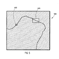
- FIG. 5 is a view of a composite image, including the 50 ⁇ and 5 ⁇ magnification areas of FIGS. 4A and 4B , respectively, displayed on a monitor of an indentation hardness test system configured according to one embodiment of the present invention
- FIG. 6 is an exemplary data structure diagram used to determine individual image locations in a composite image of a part
- FIG. 7 is a flow chart of a routine for creating a composite image of a part.
- FIGS. 8A-8G are exemplary displays provided by an indentation test system according to one embodiment of the present invention.
- a system can be implemented using an indentation hardness tester that includes: a light microscope, a digital camera positioned to collect images through the microscope, an electrically controlled stage capable of moving a test assembly, i.e., an associated part to be tested or a portion of a part mounted in a plastic, in at least two dimensions in a plane perpendicular to the lens of the light microscope, and a processor (or computer system) connected to both the camera and the stage such that the processor can display images acquired by the camera while monitoring and controlling the movements of the stage and its associated part.
- a test assembly i.e., an associated part to be tested or a portion of a part mounted in a plastic
- FIG. 1 shows a partial perspective view of an exemplary indentation hardness tester according to one embodiment of the present invention.
- the indentation hardness test system 10 includes a frame 20 with an attached motorized turret 14 , including objective lenses 16 A and 16 B, which form a portion of a light microscope, and an indenter 18 , e.g., a Knoop or Vickers indenter. It should be appreciated that additional objective lenses may be mounted on the turret 14 , if desired.
- a stage 12 is movably attached to the frame 20 such that different areas of a test assembly 22 , which is attached to the stage 12 , may be inspected.
- FIG. 1A depicts an exemplary electrical block diagram of various electrical components that may be included within the definition of the test system 10 .
- a processor. 40 is coupled to a memory subsystem 42 , an input device 44 (e.g., a joystick, a knob, a mouse and/or a keyboard) and a display 46 .
- a frame grabber 48 which is coupled between the processor 40 and a camera 52 , functions to capture frames of digital data provided by the camera 52 .
- the camera 52 may, for example, provide an RS-170 video signal to the frame grabber 48 that is digitized at a rate of 30 Hz.
- the processor 40 is also coupled to and controls a turret motor 54 to properly and selectively position the objective lenses 16 A and 16 B and the indenter 18 (e.g., a diamond tipped device), as desired. It should be appreciated that additional indenters may also be located on the turret 14 , if desired.
- the processor 40 is also coupled to stage motors (e.g., three stage motors that move the stage in three dimensions) 56 and provides commands to the stage motors 56 to cause the stage to be moved, in two or three dimensions for image capture and focusing, as desired.
- the stage motors 56 also provide position coordinates of the stage that are, as is further discussed below, correlated with the images provided by the camera 52 .
- the position coordinates of the stage may be provided by, for example, encoders associated with each of the stage motors 56 , and may, for example, be provided to the processor 40 at a rate of about 30 Hz via an RS-232 interface.
- the processor 40 may communicate with a separate stage controller that also includes its own input device, e.g., a joystick.
- the processor 40 , the memory subsystem 42 , the input device 44 and the display 46 may be incorporated within a personal computer (PC).
- the frame grabber 48 takes the form of a card that plugs into a motherboard associated with the processor 40 .
- processor may include a general purpose processor, a microcontroller (i.e., an execution unit with memory, etc., integrated within a single integrated circuit), an application specific integrated circuit (ASIC), a programmable logic device (PLD) or a digital signal processor (DSP).
- ASIC application specific integrated circuit
- PLD programmable logic device
- DSP digital signal processor
- the test assembly 22 includes a part to be tested, i.e., a portion of a gear 102 , that is mounted in the material 104 , e.g., a phenolic resin, for testing.
- the tooth 102 A of the gear 102 may typically have a face with dimensions of about 0.5 cm by 0.5 cm in which indentations are to be placed in a desired indentation pattern. As is shown in FIG. 3 , five evenly spaced indents 302 are depicted.
- a part that is to be subjected to indentation hardness testing is often measured in centimeters, while the dimensions of the indentations typically range from 10 to 100 microns.
- a typical field of view for a light microscope may range from 100 microns to 5000 microns.
- a traditional indentation hardness tester with objective lenses of 5 ⁇ and 50 ⁇ allows an operator of the system to see about 1 ⁇ 5 th of the top portion of a typical tooth at the 5 ⁇ magnification and only about 1/50 th of the top surface of the tooth at the 50 ⁇ magnification.
- a composite image 500 provides a wider field of view to allow the operator to more precisely determine where the indents are to be positioned on the tooth.
- the processor 40 collects a series of real-time images and stage coordinates as an operator manually traverses the part. In doing so, the processor 40 executes a routine that assembles the data into, i.e., renders, a composite (or panoptic) image that shows the portions of the part that have passed under an objective lens of the microscope, whose objective lens is mounted to the turret of the test system. It should be appreciated that irrespective of the magnification of the image provided, a composite image may be stored at a lower resolution, e.g., a resolution of approximately 5 microns per pixel, if memory limitations are of concern.
- a data structure diagram 600 is depicted, which is utilized to associate data with a composite image.
- the exemplary storage mechanism is based on a tree design.
- the processor 40 stores images in a time-stamped image queue, e.g., a first-in first-out (FIFO) buffer, and stage positions are recorded in a time-stamped position queue, e.g., another first-in first-out (FIFO) buffer, located in the memory subsystem 46 .
- a routine is implemented that searches for a stage position and velocity information for the period surrounding the time that the image was acquired.
- the processor 40 accurately determines where the stage 12 was when the image was acquired. This technique allows for accurate positioning of a given image in the composite image. Further, as the direction and velocity of the part is known when a given one of images is taken, Fast Fourier Transform (FFT) techniques, or other image processing techniques, may be utilized to de-blur the image.
- FFT Fast Fourier Transform
- a routine 700 is depicted that records the quality of the data of a given image, based on the objective lens 16 A or 16 B selected and the stage 12 velocity. In this manner, new image data only replaces old image data when an operator retraces a portion of the part if the calculated quality is not significantly worse.
- the routine 700 is initiated, at which point control transfers to step 702 .
- the processor 40 receives stage positions from the stage motors 56 and time-stamped images from the camera 52 , via the frame grabber 48 .
- step 706 the processor 40 interpolates the stage positions to determine the location of the stage when the image was captured.
- step 708 the processor 40 determines whether the quality (as determined by, for example, stage velocity and a current objective lens) of a particular image has improved in decision step 710 . If the quality of the image has improved, control transfers to step 711 , where the old image is replaced with a new image. Otherwise, control transfers from step 710 to step 712 , where the processor 40 retains the old image and utilizes it in the display of the composite image on the display 46 .
- a composite image created according to the present invention is well suited for high-speed modification and retrieval while using a minimal amount of computer memory, in comparison to that required for a single large dimension image. This is achieved by storing the composite image in a series of discrete sized two-dimensional tiles, organized in a binary tree by stage position (see FIG. 6 ).
- the processor 40 determines whether the operator has completed the image gathering process. If so, control transfers to step 716 , where the routine 700 terminates. Otherwise, control transfers to step 704 , where the processor 40 continues to receive and store stage positions and time-stamped images.
- portions of the part that have not been explored are indicated in a contrasting color or pattern, e.g., a lightly shaded non-gray color, with the position of the lens, i.e., a current live view, embedded in the composite image and positioned with respect to its current position on the part.
- the live view may be indicated by, for example, a thin-lined rectangle overlaid on the composite image.
- a routine is provided that allows automatic traversal of the contours of the entire part during the image capture process.
- the stage is automatically moved to that location and a live view is embedded in the composite image.
- the resolution of the live view inside the thin-lined rectangle is about 0.3 microns per pixel and outside of the rectangle the resolution is about 5 microns per pixel.
- the system may be advantageously configured such that an operator may manually move the stage with a joystick or other input device.
- the movement of the stage may be indicated in multiple ways. For example, a live view may be fixed, allowing the part to move past the objective lens or, alternatively, the composite image may be fixed and a location of the live view may move.
- Another solution that yields a more accurate rotation angle involves allowing the “T” bar to be larger than the field of view for any objective and uses a composite image to accurately position the “T” bar. As previously mentioned, this allows an operator to zoom in on any location of the part and a live view of that portion of the part may be provided at a required resolution.
- an indentation test system configured according to the present invention may implement multiple windows, each showing the composite image and being separately sizeable, zoomable and panable, if desired.
- the present invention allows the conventional “T” bar to be dispensed with and replaced with an improved similar “T” shape, whose top is elongated and can easily be aligned with the part and whose base consists of the proposed indent locations.
- shapes e.g., a line segment and a circle of a known radius, other than the “T” shape may be desirable depending upon the application.
- FIG. 8A shows a display 800 of a composite image of the gear 102 after tracing, i.e., capturing images, of an edge 802 of the gear 102 .
- the display 800 includes an embedded live image 804 with portion of the gear 102 that has not yet been captured denoted with a background pattern 806 .
- FIG. 8B shows a display 810 , which depicts a magnified view of the tooth 102 A, which includes the embedded live image 804 and a “T” shape 811 that is used to facilitate the placement of indent locations according to the present invention.
- FIG. 8A shows a display 800 of a composite image of the gear 102 after tracing, i.e., capturing images, of an edge 802 of the gear 102 .
- the display 800 includes an embedded live image 804 with portion of the gear 102 that has not yet been captured denoted with a background pattern 806 .
- FIG. 8B shows a display 810 , which depicts a magnified view
- FIG. 8C shows a display 820 that is a further magnified view of the composite image of the tooth 102 A shown in the display 810 , which also includes the live view 804 and the leg of the “T” shape 811 that is utilized for positioning indent locations.
- FIGS. 8D-8F show displays 830 , 840 and 850 , respectively, illustrating the alignment of the “T” shape with the tooth 102 A in order to facilitate placement of the indent locations.
- FIG. 8G depicts a display 860 that illustrates the proposed indent locations 813 overlaid on the composite image and a current live image 804 A.
- Embodiments of the present invention advantageously allow the indent locations 813 to be manipulated. That is, the indent locations 813 may be added or removed, moved to a new location and/or rotated/translated as a group, using an appropriated input device, i.e., mouse, keyboard, etc.
Abstract
An indentation hardness test system includes a frame having a movable turret, a movable stage for receiving a part, a camera, a display, a processor and a memory subsystem. The turret includes an objective lens of a microscope and an indenter and the movable stage is configured for receiving the part to be tested. The camera captures images of the part through the microscope, which can then be provided on the display. The processor is coupled to the turret, the movable stage, the camera and the display, as well as the memory subsystem. The memory subsystem stores executable code that instructs the processor to capture and store a series of real-time images of the part using the camera, store associated stage coordinates provided by the stage for the images and display a composite image, which includes the series of real-time images assembled according to the associated stage coordinates, of the part.
Description
This application claims the benefit of U.S. Provisional Patent Application Ser. No. 60/419,475, entitled “MICRO HARDNESS TEST SYSTEM,” which was filed Oct. 18, 2002, and which is hereby incorporated herein by reference in its entirety.
A portion of the disclosure of this patent document contains material, which is subject to copyright protection. The copyright owner has no objection to the facsimile reproduction by anyone of the patent document or the patent disclosure, as it appears in the Patent and Trademark Office patent file or records, but otherwise reserves all copyright rights whatsoever.
A computer program listing appendix on one compact disc (labeled “Computer Program Listing Appendix—Disc 1/Copy 1”) includes the following files:
| File Name | Creation Date | Size (bytes) | ||
| BasicDrawing.cpp | Oct. 1, 2003 | 1,766 | ||
| BasicDrawing.h | Oct. 1, 2003 | 1,310 | ||
| BasicHandle.cpp | Oct. 1, 2003 | 5,194 | ||
| BasicHandle.h | Oct. 1, 2003 | 3,005 | ||
| BasicNavigationPoint.cpp | Oct. 1, 2003 | 2,077 | ||
| BasicNavigationPoint.h | Oct. 1, 2003 | 1,260 | ||
| CompositeImage.cpp | Oct. 1, 2003 | 23,476 | ||
| CompositeImage.h | Oct. 1, 2003 | 1,935 | ||
| CompositeImaging.h | Oct. 1, 2003 | 714 | ||
| CompositeLiveOverlay.cpp | Oct. 1, 2003 | 8,958 | ||
| CompositeLiveOverlay.h | Oct. 1, 2003 | 1,590 | ||
| CompositeStageMediator.cpp | Oct. 1, 2003 | 5,174 | ||
| CompositeStageMediator.h | Oct. 1, 2003 | 982 | ||
| CompositeViewLayer.cpp | Oct. 1, 2003 | 6,467 | ||
| CompositeViewLayer.h | Oct. 1, 2003 | 1,502 | ||
| Drawable.h | Oct. 1, 2003 | 392 | ||
| Drawing.h | Oct. 1, 2003 | 2,152 | ||
| DrawingTool.cpp | Oct. 1, 2003 | 1,390 | ||
| DrawingTool.h | Oct. 1, 2003 | 2,255 | ||
| DrawingView.h | Oct. 1, 2003 | 1,141 | ||
| Figure.cpp | Oct. 1, 2003 | 935 | ||
| Figure.h | Oct. 1, 2003 | 4,153 | ||
| FigureBase.cpp | Oct. 1, 2003 | 3,595 | ||
| FigureBase.h | Oct. 1, 2003 | 1,729 | ||
| Geometry.cpp | Oct. 2, 2003 | 11,490 | ||
| Geometry.h | Oct. 1, 2003 | 6,242 | ||
| Grabber.cpp | Oct. 1, 2003 | 14,952 | ||
| Grabber.h | Oct. 1, 2003 | 2,950 | ||
| GrabberProvider.h | Oct. 1, 2003 | 1,184 | ||
| GraphicPrimitives.cpp | Oct. 2, 2003 | 9,612 | ||
| GraphicPrimitives.h | Oct. 1, 2003 | 4,085 | ||
| IaDoc.cpp | Oct. 1, 2003 | 23,986 | ||
| IaDoc.h | Oct. 1, 2003 | 6,228 | ||
| Image.h | Jun. 10, 2003 | 3,201 | ||
| ImageOverlay.h | Jun. 10, 2003 | 1,916 | ||
| Indent.cpp | Oct. 1, 2003 | 49,537 | ||
| Indent.h | Oct. 1, 2003 | 10,349 | ||
| IndentDrawing.cpp | Oct. 1, 2003 | 40,163 | ||
| IndentDrawing.h | Oct. 1, 2003 | 7,182 | ||
| IndentGroup.cpp | Oct. 1, 2003 | 49,011 | ||
| IndentGroup.h | Oct. 1, 2003 | 9,937 | ||
| IndentPosLine.cpp | Oct. 1, 2003 | 14,448 | ||
| IndentPosLine.h | Oct. 1, 2003 | 3,325 | ||
| IndentVector.cpp | Oct. 1, 2003 | 19,455 | ||
| IndentVector.h | Oct. 1, 2003 | 4,190 | ||
| InImageSource.cpp | Oct. 1, 2003 | 10,883 | ||
| InImageSource.h | Oct. 1, 2003 | 1,806 | ||
| MoveInfoImpl.cpp | Oct. 1, 2003 | 1,807 | ||
| MoveInfoImpl.h | Oct. 1, 2003 | 1,203 | ||
| MtCamera.h | Oct. 1, 2003 | 1,578 | ||
| MtStage.cpp | Oct. 1, 2003 | 54,322 | ||
| MtStage.h | Oct. 1, 2003 | 15,851 | ||
| MtStageCom.cpp | Oct. 1, 2003 | 13,620 | ||
| MtStageCom.h | Oct. 1, 2003 | 2,094 | ||
| MtTrace.cpp | Jul. 22, 2003 | 21,219 | ||
| MtTrace.h | Jun. 10, 2003 | 3,314 | ||
| NavigationPoint.h | Oct. 1, 2003 | 1,818 | ||
| Objective.cpp | Jun. 10, 2003 | 7,464 | ||
| Objective.h | Jun. 10, 2003 | 2,481 | ||
| PanopticSettings.h | Oct. 1, 2003 | 713 | ||
| PanopticView.cpp | Oct. 1, 2003 | 43,831 | ||
| PanopticView.h | Oct. 1, 2003 | 5,994 | ||
| PatternPreferences.cpp | Oct. 1, 2003 | 3,542 | ||
| PatternPreferences.h | Oct. 1, 2003 | 2,946 | ||
| PositionTool.cpp | Oct. 1, 2003 | 10,992 | ||
| PositionTool.h | Oct. 1, 2003 | 1,465 | ||
| TextFigure.cpp | Oct. 2, 2003 | 6,380 | ||
| TextFigure.h | Oct. 2, 2003 | 2,929 | ||
| TransformationMatrix2D.cpp | Oct. 1, 2003 | 3,771 | ||
| TransformationMatrix2D.h | Oct. 1, 2003 | 1,915 | ||
| ViewLayer.h | Oct. 1, 2003 | 565 | ||
and an identical copy (labeled “Computer Program Listing Appendix—Disc 1/Copy 2”) of the compact disc (labeled “Computer Program Listing Appendix—Disc 1/Copy 1”) are attached hereto. The files included on Disc 1/Copy 1 on CD-R are in ASCII file format. The above-referenced computer program listing provided on the compact disc labeled “Computer Program Listing Appendix—Disc 1/Copy 1” is hereby incorporated herein by reference in its entirety.
The present invention is generally directed to a test system and, more specifically, to an indentation hardness test system.
Hardness testing has been found to be useful for material evaluation and quality control of manufacturing processes and research and development endeavors. The hardness of an object, although empirical in nature, can be correlated to tensile strength for many metals and provides an indicator of wear-resistance and ductility of a material. A typical indentation hardness tester utilizes a calibrated machine to force a diamond indenter (of a desired geometry) into the surface of a material being evaluated. The indentation dimension (dimensions) is (are) then measured with a light microscope after load removal. A determination of the hardness of the material under test may then be obtained by dividing the force applied to the indenter by the projected area of the permanent impression made by the indenter.
In a typical situation, an operator of an indentation hardness tester is required to position indents into a part at precise distances from various part geometries. With reference to FIGS. 2 and 3 , an operator may be required to place a series of five evenly spaced indents 302 into a surface of a tooth 102A of a portion of, for example, a gear 102 being tested and mounted within a plastic 104 to form a test assembly 22. The indents 302 may be spaced 200 microns (±5 microns) from each other and centered in a face of the tooth 102A. Assuming that the tooth 102A is approximately 0.5 cm wide by 0.5 cm tall and the tester has two magnifications, i.e., a high power 50× objective with a field of view 200 microns wide and a 5× magnification with a field of view 2000 microns wide, and assuming that an image of the tooth 102A is displayed on a display having a width of 640 pixels, the width of each pixel is about 0.3 microns at 50× and about 3.0 microns at 5× magnification.
In such a tester, a 5× magnification only allows an operator to see about ⅕th of the top surface of a tooth and a 50× magnification only allows the operator to see about 1/50th of the top surface of a tooth. It should be appreciated that such a view does not allow an operator to precisely know if a stage that is used to position the test assembly 22 is positioned in the center of the top surface of the tooth. Thus, to ensure that indentations are perpendicular to the top of the tooth 102A and a specified distance from the top surface of the tooth 102A, traditional software packages have allowed an operator to position a “T” bar along a displayed image. In this manner, an operator would position the top portion of the “T” bar along the top edge of the tooth 102A through a combination of moving the stage and rotating the “T” bar. As briefly described above, at 5× magnification the operator has a relatively good idea of the required orientation of the “T” bar, but not enough resolution to position it within 5 microns of the edge. Further, at 50× magnification, locating the top edge of the tooth within 5 microns is possible, but the orientation is difficult because the edge is not straight at this magnification.
What is needed is a technique that more readily allows an operator of an indentation hardness tester to properly position an indenter with respect to a test assembly.
The present invention is generally directed to an indentation hardness test system that includes a frame having a movable turret, a movable stage for receiving a part, a camera, a display, a processor and a memory subsystem. The turret includes a first objective lens of a microscope and an indenter and the movable stage is configured for receiving a part to be tested. The camera captures images of the part through the microscope, which can then be provided on the display. The processor is electrically coupled to the turret, the movable stage, the camera and the display, as well as the memory subsystem. The memory subsystem stores code that, when executed, instructs the processor to perform a number of steps. That is, the code instructs the processor to capture and store a series of real-time images of the part using the camera. The code also instructs the processor to store stage coordinates, associated with each of the images, and to display a composite image of the part, which includes the series of real-time images assembled according to the associated stage coordinates, on the display.
According to another embodiment of the present invention, the images are stored at a lower resolution than the captured images. According to still another embodiment of the present invention, the code instructs the processor to perform the additional step of displaying a background pattern in the composite image for the portions of the part that have not been captured. According to yet another embodiment of the present invention, the code instructs the processor to perform the additional step of normalizing the series of real-time images when at least one of the images was captured by a second objective lens, with a different focal length than the first objective lens, before displaying the composite image of the part.
In another embodiment, the code instructs the processor to perform the additional step of displaying an outline of the part in a composite image. The step of displaying an outline of the part in the composite image may also include the steps of: examining a frame of an image stream of the part to locate an edge of the part and moving the part in a direction parallel to the edge of the part such that the edge remains in the field of view for a next frame until the outline of the part is complete. The code may also cause the processor to perform the additional steps of overlaying a current position image of the part in the composite image and indicating a location of the current positioned image. Further, the code may allow the processor to perform the additional steps of overlaying an indent position diagram on the composite image and displaying a proposed indent location within an indentation outline that represents a geometry and size (based upon an expected indenter), an expected orientation of the indenter, an expected indenter load and an expected hardness of the part.
These and other features, advantages and objects of the present invention will be further understood and appreciated by those skilled in the art by reference to the following specification, claims and appended drawings.
In the drawings:
A system according to various embodiments of the present invention can be implemented using an indentation hardness tester that includes: a light microscope, a digital camera positioned to collect images through the microscope, an electrically controlled stage capable of moving a test assembly, i.e., an associated part to be tested or a portion of a part mounted in a plastic, in at least two dimensions in a plane perpendicular to the lens of the light microscope, and a processor (or computer system) connected to both the camera and the stage such that the processor can display images acquired by the camera while monitoring and controlling the movements of the stage and its associated part.
With reference again to FIG. 2 , the test assembly 22 includes a part to be tested, i.e., a portion of a gear 102, that is mounted in the material 104, e.g., a phenolic resin, for testing. With reference to FIG. 3 , the tooth 102A of the gear 102 may typically have a face with dimensions of about 0.5 cm by 0.5 cm in which indentations are to be placed in a desired indentation pattern. As is shown in FIG. 3 , five evenly spaced indents 302 are depicted. In a typical situation, a part that is to be subjected to indentation hardness testing is often measured in centimeters, while the dimensions of the indentations typically range from 10 to 100 microns. A typical field of view for a light microscope may range from 100 microns to 5000 microns. As previously discussed, and with reference to FIGS. 4B and 4A , respectively, a traditional indentation hardness tester with objective lenses of 5× and 50× allows an operator of the system to see about ⅕th of the top portion of a typical tooth at the 5× magnification and only about 1/50th of the top surface of the tooth at the 50× magnification. As mentioned above, it is often difficult for the operator to know if the stage is positioned in the center of the face of the tooth when the magnification is set at 50×. According to the present invention and as is shown in FIG. 5 , a composite image 500 provides a wider field of view to allow the operator to more precisely determine where the indents are to be positioned on the tooth.
According to one embodiment of the present invention, the processor 40 collects a series of real-time images and stage coordinates as an operator manually traverses the part. In doing so, the processor 40 executes a routine that assembles the data into, i.e., renders, a composite (or panoptic) image that shows the portions of the part that have passed under an objective lens of the microscope, whose objective lens is mounted to the turret of the test system. It should be appreciated that irrespective of the magnification of the image provided, a composite image may be stored at a lower resolution, e.g., a resolution of approximately 5 microns per pixel, if memory limitations are of concern.
With reference to FIG. 6 , a data structure diagram 600 is depicted, which is utilized to associate data with a composite image. As can be seen, from review of FIG. 6 , the exemplary storage mechanism is based on a tree design. To correlate images from the camera 52, the processor 40 stores images in a time-stamped image queue, e.g., a first-in first-out (FIFO) buffer, and stage positions are recorded in a time-stamped position queue, e.g., another first-in first-out (FIFO) buffer, located in the memory subsystem 46. For each given image in the queue, a routine is implemented that searches for a stage position and velocity information for the period surrounding the time that the image was acquired. Then, using interpolation, the processor 40 accurately determines where the stage 12 was when the image was acquired. This technique allows for accurate positioning of a given image in the composite image. Further, as the direction and velocity of the part is known when a given one of images is taken, Fast Fourier Transform (FFT) techniques, or other image processing techniques, may be utilized to de-blur the image.
With reference to FIG. 7 , a routine 700 is depicted that records the quality of the data of a given image, based on the objective lens 16A or 16B selected and the stage 12 velocity. In this manner, new image data only replaces old image data when an operator retraces a portion of the part if the calculated quality is not significantly worse. In step 702, the routine 700 is initiated, at which point control transfers to step 702. Next, in step 704, the processor 40 receives stage positions from the stage motors 56 and time-stamped images from the camera 52, via the frame grabber 48. Next, in step 706, the processor 40 interpolates the stage positions to determine the location of the stage when the image was captured. The acquired images are then processed using various techniques, e.g., de-interlacing, de-blurring, shade correction and stretching/shrinking. After processing the image, in step 708, the processor 40 determines whether the quality (as determined by, for example, stage velocity and a current objective lens) of a particular image has improved in decision step 710. If the quality of the image has improved, control transfers to step 711, where the old image is replaced with a new image. Otherwise, control transfers from step 710 to step 712, where the processor 40 retains the old image and utilizes it in the display of the composite image on the display 46.
A composite image created according to the present invention is well suited for high-speed modification and retrieval while using a minimal amount of computer memory, in comparison to that required for a single large dimension image. This is achieved by storing the composite image in a series of discrete sized two-dimensional tiles, organized in a binary tree by stage position (see FIG. 6). Next, in decision step 714, the processor 40 determines whether the operator has completed the image gathering process. If so, control transfers to step 716, where the routine 700 terminates. Otherwise, control transfers to step 704, where the processor 40 continues to receive and store stage positions and time-stamped images.
According to one embodiment of the present invention, portions of the part that have not been explored are indicated in a contrasting color or pattern, e.g., a lightly shaded non-gray color, with the position of the lens, i.e., a current live view, embedded in the composite image and positioned with respect to its current position on the part. The live view may be indicated by, for example, a thin-lined rectangle overlaid on the composite image. According to another embodiment of the present invention, in order to speed up the capturing of the image of the part, a routine is provided that allows automatic traversal of the contours of the entire part during the image capture process.
According to the present invention, as the operator zooms in on any portion of the composite image, the stage is automatically moved to that location and a live view is embedded in the composite image. In one embodiment, when the objective is set at 50× magnification, the resolution of the live view inside the thin-lined rectangle is about 0.3 microns per pixel and outside of the rectangle the resolution is about 5 microns per pixel. As mentioned above, the system may be advantageously configured such that an operator may manually move the stage with a joystick or other input device. When the system is set up such that a routine is controlling the movement of the stage, the movement of the stage may be indicated in multiple ways. For example, a live view may be fixed, allowing the part to move past the objective lens or, alternatively, the composite image may be fixed and a location of the live view may move.
As previously discussed, traditional indentation hardness test systems have allowed an operator to position a “T” bar along a surface of the part to be tested to ensure that the indentations are perpendicular to the top surface of the gear tooth and at a specified distance from the top surface. However, as previously discussed, at 5× magnification the operator has a relatively good idea of the required orientation of the “T” bar, but not enough resolution to position it within 5 microns of the edge. Further, at 50× magnification, locating the edge within 5 microns is possible but the orientation of the “T” bar is difficult because the edge is not straight at this magnification level. One solution to this problem is to rotate the “T” bar at 5× magnification and position it on the edge at 50× magnification. Another solution that yields a more accurate rotation angle involves allowing the “T” bar to be larger than the field of view for any objective and uses a composite image to accurately position the “T” bar. As previously mentioned, this allows an operator to zoom in on any location of the part and a live view of that portion of the part may be provided at a required resolution.
Traditional indentation hardness test systems have displayed a pattern of desired indents in a separate window. In these systems, an operator has manipulated the indent locations in the pattern window and then instructed the system to make the indents in the part. However, as previously discussed, it is difficult for an operator to correlate the proposed indent locations in a pattern window with the exact position on the part as seen in a live view. Advantageously, embodiments of the present invention allow a pattern window to be overlaid on top of a composite image. Thus, an operator may position indents with respect to large scale features of the part and with respect to the low resolution composite image. In this manner, an operator can then fine tune the indent locations by zooming in and viewing the indent positions through an embedded live view. Further, in a system so configured, screen display area is conserved as only one window is required. That is, multiple windows, each showing a different layer of data, are not required as a composite image of a part may be shown in one window on an indentation test system configured according to the present invention. However, it should be appreciated that an indentation test system configured according to the present invention may implement multiple windows, each showing the composite image and being separately sizeable, zoomable and panable, if desired. According to one embodiment, the present invention allows the conventional “T” bar to be dispensed with and replaced with an improved similar “T” shape, whose top is elongated and can easily be aligned with the part and whose base consists of the proposed indent locations. However, it should be appreciated that shapes, e.g., a line segment and a circle of a known radius, other than the “T” shape may be desirable depending upon the application.
Accordingly, a number of techniques have been described herein that advantageously allow an operator of an indentation hardness test system to readily position indent locations in a part that is to be hardness tested.
The above description is considered that of the preferred embodiments only. Modifications of the invention will occur to those skilled in the art and to those who make or use the invention. Therefore, it is understood that the embodiments shown in the drawings and described above are merely for illustrative purposes and not intended to limit the scope of the invention, which is defined by the following claims as interpreted according to the principles of patent law, including the doctrine of equivalents.
Claims (23)
1. An indentation hardness test system, comprising:
a frame including an attached movable turret, wherein the turret includes a first objective lens that forms a portion of a microscope and an indenter;
a movable stage for receiving a part attached to the frame;
a camera for capturing images of the part through the microscope;
a display;
a processor electrically coupled to at least a portion of the turret, the movable stage, the camera and the display; and
a memory subsystem coupled to the processor, the memory subsystem storing code that when executed instructs the processor to perform the steps of:
capturing and storing a series of real-time images of the part, wherein the real-time images are provided by the camera;
storing associated stage coordinates for the real-time images, wherein the stage coordinates are provided by the stage; and
displaying a composite image of the part, wherein the composite image includes the series of real-time images assembled according to the associated stage coordinates.
2. The system of claim 1 , wherein the series of real-time images are stored at a lower resolution than the captured images.
3. The system of claim 1 , wherein the code instructs the processor to perform the additional step of:
displaying a background pattern in the composite image for portions of the part that have not been captured.
4. The system of claim 1 , wherein the code instructs the processor to perform the additional step of:
normalizing the series of real-time images when at least one of the real-time images was captured by a second objective lens with a different focal length than the first objective lens before displaying the composite image of the part.
5. The system of claim 1 , wherein the code instructs the processor to perform the additional step of:
displaying an outline of the part in the composite image.
6. The system of claim 5 , wherein the step of displaying an outline of the part in the composite image includes the steps of:
examining a frame of an image stream of the part to locate an edge of the part; and
moving the part in a direction parallel to the edge of the part such that the edge remains in the field of view for a next frame until the outline of the part is complete.
7. The system of claim 1 , wherein the code instructs the processor to perform the additional steps of:
overlaying a current position image of the part in the composite image; and
indicating a location of the current position image.
8. The system of claim 1 , wherein the code instructs the processor to perform the additional steps of:
overlaying an indent position diagram on the composite image; and
displaying a proposed indent location with an indentation outline that represents a geometry and size based upon an expected indenter, an expected orientation of the indenter, an expected indenter load and an expected hardness of the part.
9. An indentation hardness test system, comprising:
a frame including an attached movable turret, wherein the turret includes a first objective lens that forms a portion of a microscope and an indenter;
a movable stage for receiving a part attached to the frame;
a camera for capturing images of the part through the microscope;
a display;
a processor electrically coupled to at least a portion of the turret, the movable stage, the camera and the display; and
a memory subsystem coupled to the processor, the memory subsystem storing code that when executed instructs the processor to perform the steps of:
capturing and storing a series of real-time images of the part, wherein the real-time images are provided by the camera;
storing associated stage coordinates for the real-time images, wherein the stage coordinates are provided by the stage; and
displaying a composite image of the part, wherein the composite image includes the series of real-time images assembled according to the associated stage coordinates, and wherein the composite image includes a background pattern for portions of the part that have not been captured.
10. The system of claim 9 , wherein the series of real-time images are stored at a lower resolution than the captured images.
11. The system of claim 9 , wherein the code instructs the processor to perform the additional step of:
normalizing the series of real-time images when at least one of the real-time images was captured by a second objective lens with a different focal length than the first objective lens before displaying the composite image of the part.
12. The system of claim 9 , wherein the code instructs the processor to perform the additional step of:
displaying an outline of the part in the composite image.
13. The system of claim 12 , wherein the step of displaying an outline of the part in the composite image includes the steps of:
examining a frame of an image stream of the part to locate an edge of the part; and
moving the part in a direction parallel to the edge of the part such that the edge remains in the field of view for a next frame until the outline of the part is complete.
14. The system of claim 9 , wherein the code instructs the processor to perform the additional steps of:
overlaying a current position image of the part in the composite image; and
indicating a location of the current position image.
15. The system of claim 9 , wherein the code instructs the processor to perform the additional steps of:
overlaying an indent position diagram on the composite image; and
displaying a proposed indent location with an indentation outline that represents a geometry and size based upon an expected indenter, an expected orientation of the indenter, an expected indenter load and an expected hardness of the part.
16. An indentation hardness test system, comprising:
a frame including an attached movable turret, wherein the turret includes a first objective lens that forms a portion of a microscope and an indenter;
a movable stage for receiving a part attached to the frame;
a camera for capturing images of the part through the microscope;
a display;
a processor electrically coupled to at least a portion of the turret, the movable stage, the camera and the display; and
a memory subsystem coupled to the processor, the memory subsystem storing code that when executed instructs the processor to perform the steps of:
capturing and storing a series of real-time images of the part, wherein the real-time images are provided by the camera;
storing associated stage coordinates for the real-time images, wherein the stage coordinates are provided by the stage;
displaying a composite image of the part, wherein the composite image includes the series of real-time images assembled according to the associated stage coordinates, and wherein the composite image includes a background pattern for portions of the part that have not been captured;
overlaying a current position image of the part in the composite image; and
indicating a location of the current position image.
17. The system of claim 16 , wherein the series of real-time images are stored at a lower resolution than the captured images.
18. The system of claim 16 , wherein the code instructs the processor to perform the additional step of:
normalizing the series of real-time images when at least one of images was captured by a second objective lens with a different focal length than the first objective lens before displaying the composite image of the part.
19. The system of claim 16 , wherein the code instructs the processor to perform the additional step of:
displaying an outline of the part in the composite image.
20. The system of claim 19 , wherein the step of displaying an outline of the part in the composite image includes the steps of:
examining a frame of an image stream of the part to locate an edge of the part; and
moving the part in a direction parallel to the edge of the part such that the edge remains in the field of view for a next frame until the outline of the part is complete.
21. The system of claim 16 , wherein the code instructs the processor to perform the additional steps of:
overlaying an indent position diagram on the composite image; and
displaying a proposed indent location with an indentation outline that represents a geometry and size based upon an expected indenter, an expected orientation of the indenter, an expected indenter load and an expected hardness of the part.
22. A method for providing a composite image of a part, comprising the steps of:
capturing and storing a series of real-time images of a part, wherein the real-time images are provided by a camera;
storing associated stage coordinates for the series of real-time images, wherein the stage coordinates are provided by a stage, and wherein the part is attached to the stage;
displaying a composite image of the part, wherein the composite image includes the series of real-time images assembled according to the associated stage coordinates;
overlaying a current position image of the part in the composite image; and
indicating a location of the current position image.
23. The method of claim 22 , further including the step of:
displaying a plurality of manipulatable indent locations on the composite image.
Priority Applications (9)
| Application Number | Priority Date | Filing Date | Title |
|---|---|---|---|
| US10/679,823 US6996264B2 (en) | 2002-10-18 | 2003-10-06 | Indentation hardness test system |
| PCT/US2003/032704 WO2004036178A2 (en) | 2002-10-18 | 2003-10-16 | Indentation hardness test system |
| EA200500680A EA006837B1 (en) | 2002-10-18 | 2003-10-16 | Indentation hardness test system and method therefor |
| AU2003284238A AU2003284238A1 (en) | 2002-10-18 | 2003-10-16 | Indentation hardness test system |
| CN200710089897XA CN101034049B (en) | 2002-10-18 | 2003-10-16 | Indentation hardness test system |
| KR1020057006515A KR100969413B1 (en) | 2002-10-18 | 2003-10-16 | Indentation hardness test system |
| EP11176994A EP2386982A1 (en) | 2002-10-18 | 2003-10-16 | Indentation hardness test system |
| EP03776418A EP1559059B1 (en) | 2002-10-18 | 2003-10-16 | Indentation hardness test system |
| US11/170,694 US7139422B2 (en) | 2002-10-18 | 2005-06-29 | Indentation hardness test system |
Applications Claiming Priority (2)
| Application Number | Priority Date | Filing Date | Title |
|---|---|---|---|
| US41947502P | 2002-10-18 | 2002-10-18 | |
| US10/679,823 US6996264B2 (en) | 2002-10-18 | 2003-10-06 | Indentation hardness test system |
Related Child Applications (1)
| Application Number | Title | Priority Date | Filing Date |
|---|---|---|---|
| US11/170,694 Continuation US7139422B2 (en) | 2002-10-18 | 2005-06-29 | Indentation hardness test system |
Publications (2)
| Publication Number | Publication Date |
|---|---|
| US20040096093A1 US20040096093A1 (en) | 2004-05-20 |
| US6996264B2 true US6996264B2 (en) | 2006-02-07 |
Family
ID=32110248
Family Applications (2)
| Application Number | Title | Priority Date | Filing Date |
|---|---|---|---|
| US10/679,823 Expired - Lifetime US6996264B2 (en) | 2002-10-18 | 2003-10-06 | Indentation hardness test system |
| US11/170,694 Expired - Lifetime US7139422B2 (en) | 2002-10-18 | 2005-06-29 | Indentation hardness test system |
Family Applications After (1)
| Application Number | Title | Priority Date | Filing Date |
|---|---|---|---|
| US11/170,694 Expired - Lifetime US7139422B2 (en) | 2002-10-18 | 2005-06-29 | Indentation hardness test system |
Country Status (6)
| Country | Link |
|---|---|
| US (2) | US6996264B2 (en) |
| EP (2) | EP2386982A1 (en) |
| KR (1) | KR100969413B1 (en) |
| AU (1) | AU2003284238A1 (en) |
| EA (1) | EA006837B1 (en) |
| WO (1) | WO2004036178A2 (en) |
Cited By (6)
| Publication number | Priority date | Publication date | Assignee | Title |
|---|---|---|---|---|
| US20090145208A1 (en) * | 2007-11-27 | 2009-06-11 | Csm Instruments Sa | Method for analyzing a scratch test |
| US20130068001A1 (en) * | 2011-09-15 | 2013-03-21 | Mitutoyo Corporation | Hardness tester and hardness test method |
| US20140267679A1 (en) * | 2013-03-13 | 2014-09-18 | Leco Corporation | Indentation hardness test system having an autolearning shading corrector |
| US9429466B2 (en) | 2013-10-31 | 2016-08-30 | Halliburton Energy Services, Inc. | Distributed acoustic sensing systems and methods employing under-filled multi-mode optical fiber |
| US20180293726A1 (en) * | 2017-04-05 | 2018-10-11 | Asmec Advanced Surface Mechanics Gmbh | Method for the Analysis of Surface Measurements |
| US11099111B2 (en) * | 2016-11-04 | 2021-08-24 | Zf Friedrichshafen Ag | Test coupon and test method |
Families Citing this family (34)
| Publication number | Priority date | Publication date | Assignee | Title |
|---|---|---|---|---|
| US7389181B2 (en) * | 2004-08-31 | 2008-06-17 | Visre, Inc. | Apparatus and method for producing video drive-by data corresponding to a geographic location |
| US20040192343A1 (en) * | 2003-01-28 | 2004-09-30 | Kentaro Toyama | System and method for location annotation employing time synchronization |
| US8207964B1 (en) | 2008-02-22 | 2012-06-26 | Meadow William D | Methods and apparatus for generating three-dimensional image data models |
| US7929800B2 (en) | 2007-02-06 | 2011-04-19 | Meadow William D | Methods and apparatus for generating a continuum of image data |
| US8078396B2 (en) * | 2004-08-31 | 2011-12-13 | Meadow William D | Methods for and apparatus for generating a continuum of three dimensional image data |
| JP2006071415A (en) * | 2004-09-01 | 2006-03-16 | Mitsutoyo Corp | Hardness tester |
| US7263898B1 (en) | 2004-11-22 | 2007-09-04 | Honda Motor Co., Ltd. | Fixture for holding a gear |
| IT1393943B1 (en) * | 2009-04-10 | 2012-05-17 | Affri | UNIVERSAL-TYPE DUROMETER WITH READY-OF-FORM READING DEVICE. |
| DE102009019256B4 (en) * | 2009-04-30 | 2016-08-18 | Illinois Tool Works Inc. | Hardness tester for testing the hardness impression |
| IT1395731B1 (en) * | 2009-08-03 | 2012-10-19 | Affri | TEST MACHINE PARTICULARLY FOR INSTRUMENTED INDENTATION TESTS. |
| US8132447B2 (en) * | 2009-12-09 | 2012-03-13 | Shaoming Wu | Universal testing machine |
| JP5501189B2 (en) * | 2010-10-06 | 2014-05-21 | 株式会社ミツトヨ | Hardness testing machine |
| JP2012078306A (en) * | 2010-10-06 | 2012-04-19 | Mitsutoyo Corp | Hardness test apparatus |
| JP5777957B2 (en) * | 2011-07-05 | 2015-09-16 | 株式会社ミツトヨ | Hardness tester and hardness test method |
| JP2013050379A (en) * | 2011-08-31 | 2013-03-14 | Mitsutoyo Corp | Hardness-testing machine |
| JP5841379B2 (en) * | 2011-08-31 | 2016-01-13 | 株式会社ミツトヨ | Hardness testing machine |
| JP5923824B2 (en) * | 2012-02-21 | 2016-05-25 | 株式会社ミツトヨ | Image processing device |
| JP5977556B2 (en) * | 2012-03-27 | 2016-08-24 | 株式会社ミツトヨ | Hardness testing machine |
| US20150075264A1 (en) * | 2012-03-27 | 2015-03-19 | Hysitron, Inc. | Microscope objective mechanical testing instrument |
| US9063048B2 (en) * | 2012-07-12 | 2015-06-23 | Mitutoyo Corporation | Hardness tester and program |
| JP6016620B2 (en) * | 2012-12-26 | 2016-10-26 | 株式会社ミツトヨ | Hardness tester and hardness test method |
| JP6040816B2 (en) * | 2013-03-19 | 2016-12-07 | 株式会社島津製作所 | Hardness testing machine |
| JP6094457B2 (en) * | 2013-11-05 | 2017-03-15 | 株式会社島津製作所 | Hardness testing machine |
| US20160299498A1 (en) * | 2015-04-10 | 2016-10-13 | Nanovea, Inc. | System for navigating a field of view of a displayed and magnified surface |
| JP6559023B2 (en) * | 2015-09-10 | 2019-08-14 | 株式会社ミツトヨ | Hardness tester and hardness test method |
| JP6560937B2 (en) * | 2015-09-10 | 2019-08-14 | 株式会社ミツトヨ | Hardness tester and hardness test method |
| JP6471684B2 (en) * | 2015-12-21 | 2019-02-20 | 株式会社島津製作所 | Hardness testing machine |
| CN105758713B (en) * | 2016-05-12 | 2018-05-25 | 东北大学 | A kind of three-in-one nano-indentation experiment method |
| AT518859B1 (en) * | 2016-08-12 | 2018-02-15 | Qness Gmbh | Method and device for hardness testing |
| CN110100175A (en) * | 2017-02-02 | 2019-08-06 | 伊斯梅卡半导体控股公司 | Component and method for inspection part |
| JP2018165643A (en) * | 2017-03-28 | 2018-10-25 | 株式会社ミツトヨ | Hardness testing machine and program |
| DE102017115963A1 (en) * | 2017-07-14 | 2019-01-17 | Atm Gmbh | Eindruckhärteprüfgerät |
| JP7348040B2 (en) | 2019-11-21 | 2023-09-20 | 株式会社ミツトヨ | Hardness tester and program |
| KR102521067B1 (en) * | 2021-03-15 | 2023-04-13 | 서울대학교 산학협력단 | Evaluation system of directionality of material yield strength using spherical indentation and surface displacement analysis |
Citations (39)
| Publication number | Priority date | Publication date | Assignee | Title |
|---|---|---|---|---|
| US4589140A (en) | 1983-03-21 | 1986-05-13 | Beltronics, Inc. | Method of and apparatus for real-time high-speed inspection of objects for identifying or recognizing known and unknown portions thereof, including defects and the like |
| US4618938A (en) | 1984-02-22 | 1986-10-21 | Kla Instruments Corporation | Method and apparatus for automatic wafer inspection |
| US4757550A (en) | 1984-05-21 | 1988-07-12 | Disco Abrasive Systems, Ltd. | Automatic accurate alignment system |
| US4764969A (en) | 1986-01-28 | 1988-08-16 | Kabushiki Kaisha Toshiba | Apparatus for inspecting the surface of a material |
| US4825388A (en) | 1986-04-01 | 1989-04-25 | Princeton Gamma Tech., Inc. | Apparatus and method for processing digital images |
| US4945490A (en) * | 1988-04-11 | 1990-07-31 | Biddle Jr Ernest L | Brinell hardness indicator with digital readout |
| US5022089A (en) | 1990-01-19 | 1991-06-04 | Wilson Monti R | Method and apparatus for fast registration using crosshair register marks |
| US5146779A (en) | 1989-09-05 | 1992-09-15 | Nippon Steel Corporation | Indentation hardness tester |
| US5264919A (en) | 1991-04-19 | 1993-11-23 | Kabushiki Kaisha Toshiba | Apparatus for positioning a semiconductor wafer |
| US5486924A (en) | 1991-10-23 | 1996-01-23 | Phase Metrics | Method and apparatus for measurement of roughness and hardness of a surface |
| US5513275A (en) | 1993-01-12 | 1996-04-30 | Board Of Trustees Of The Leland Stanford Junior University | Automated direct patterned wafer inspection |
| US5517235A (en) | 1993-11-03 | 1996-05-14 | Control Automation, Inc. | Method and apparatus for inspecting printed circuit boards at different magnifications |
| US5586058A (en) | 1990-12-04 | 1996-12-17 | Orbot Instruments Ltd. | Apparatus and method for inspection of a patterned object by comparison thereof to a reference |
| US5592563A (en) | 1992-02-17 | 1997-01-07 | Zahavi; Dov | Imaging of 3-dimensional objects |
| US5619429A (en) | 1990-12-04 | 1997-04-08 | Orbot Instruments Ltd. | Apparatus and method for inspection of a patterned object by comparison thereof to a reference |
| US5717780A (en) | 1993-07-13 | 1998-02-10 | Sharp Kabushiki Kaisha | Checking apparatus for flat type display panels |
| US5768401A (en) | 1995-08-02 | 1998-06-16 | Lucent Technologies Inc. | Balanced focus system and method for achieving optimal focus of different areas of an object that are concurrently imaged |
| US5796861A (en) | 1996-07-12 | 1998-08-18 | Frim International, Inc. | Mosaic construction, processing, and review of very large electronic micrograph composites |
| US5949389A (en) | 1995-11-15 | 1999-09-07 | University Of Strathclyde | Imaging system |
| US5987189A (en) | 1996-12-20 | 1999-11-16 | Wyko Corporation | Method of combining multiple sets of overlapping surface-profile interferometric data to produce a continuous composite map |
| US5991461A (en) | 1996-12-20 | 1999-11-23 | Veeco Corporation | Selection process for sequentially combining multiple sets of overlapping surface-profile interferometric data to produce a continuous composite map |
| US5999262A (en) | 1996-04-19 | 1999-12-07 | Carl Zeiss Jena Gmbh | Process and apparatus for detecting structural changes of specimens |
| US6031930A (en) | 1996-08-23 | 2000-02-29 | Bacus Research Laboratories, Inc. | Method and apparatus for testing a progression of neoplasia including cancer chemoprevention testing |
| US6078681A (en) | 1996-03-18 | 2000-06-20 | Marine Biological Laboratory | Analytical imaging system and process |
| US6144028A (en) | 1994-07-28 | 2000-11-07 | General Nanotechnology, L.L.C. | Scanning probe microscope assembly and method for making confocal, spectrophotometric, Near-Field, and Scanning probe measurements and associated images |
| US6201899B1 (en) | 1998-10-09 | 2001-03-13 | Sarnoff Corporation | Method and apparatus for extended depth of field imaging |
| US6219437B1 (en) | 1991-05-24 | 2001-04-17 | Forensic Technology Wai Inc. | Method and apparatus for obtaining a signature from a fired bullet |
| US6268611B1 (en) | 1997-12-18 | 2001-07-31 | Cellavision Ab | Feature-free registration of dissimilar images using a robust similarity metric |
| US6272235B1 (en) | 1997-03-03 | 2001-08-07 | Bacus Research Laboratories, Inc. | Method and apparatus for creating a virtual microscope slide |
| US20010030654A1 (en) | 2000-03-14 | 2001-10-18 | Nikon Corporation | Image processing apparatus and computer-readable medium |
| US6345129B1 (en) | 1999-02-03 | 2002-02-05 | Oren Aharon | Wide-field scanning tv |
| US6347150B1 (en) | 1996-09-17 | 2002-02-12 | Hitachi, Ltd. | Method and system for inspecting a pattern |
| US6362832B1 (en) | 1999-09-01 | 2002-03-26 | Packard Bioscience Company | Method and system for overlaying at least three microarray images to obtain a multicolor composite image |
| US20020036775A1 (en) | 2000-08-08 | 2002-03-28 | Carl Zeiss Jena Gmbh | Method for increasing the spectral and spatial resolution of detectors |
| US6587597B1 (en) | 1999-01-21 | 2003-07-01 | Nec Corporation | Image input method, image input apparatus, and recording medium |
| US20030231408A1 (en) | 2002-06-15 | 2003-12-18 | Carl Zeiss Jena Gmbh | Optical arrangement for obtaining information from a sample or an observed object |
| US6731390B2 (en) | 1999-07-01 | 2004-05-04 | Carl Zeiss Jena Gmbh | Process and apparatus for determining surface information using a projected structure with a periodically changing brightness curve |
| US20040095576A1 (en) | 2002-11-15 | 2004-05-20 | Carl Zeiss Jena Gmbh | Method and arrangement for deeply resolved optical detection of a sample |
| US20040159797A1 (en) | 2002-09-04 | 2004-08-19 | Carl Zeiss Jena Gmbh | Method and arrangement for changing the spectral composition and/or intensity of illumination light and/or specimen light in an adjustable manner |
Family Cites Families (7)
| Publication number | Priority date | Publication date | Assignee | Title |
|---|---|---|---|---|
| US5912720A (en) * | 1997-02-13 | 1999-06-15 | The Trustees Of The University Of Pennsylvania | Technique for creating an ophthalmic augmented reality environment |
| AU1182401A (en) * | 1999-10-15 | 2001-04-23 | Cellavision Ab | Microscope and method for manufacturing a composite image with a high resolution |
| US6873747B2 (en) | 2000-07-25 | 2005-03-29 | Farid Askary | Method for measurement of pitch in metrology and imaging systems |
| US6895126B2 (en) | 2000-10-06 | 2005-05-17 | Enrico Di Bernardo | System and method for creating, storing, and utilizing composite images of a geographic location |
| DE10110109A1 (en) * | 2001-03-02 | 2002-09-05 | Ernst Friedrich Mueller | Positioning of a sample for a microscope or for hardness testing has an indication arrow showing direction and speed of movement of a sample on a monitor that is used interactively with a computer and related input devices |
| JP3432212B2 (en) | 2001-03-07 | 2003-08-04 | キヤノン株式会社 | Image processing apparatus and method |
| US20040065576A1 (en) * | 2002-10-07 | 2004-04-08 | Greg Deitz | Sports container projectile |
-
2003
- 2003-10-06 US US10/679,823 patent/US6996264B2/en not_active Expired - Lifetime
- 2003-10-16 KR KR1020057006515A patent/KR100969413B1/en not_active IP Right Cessation
- 2003-10-16 EP EP11176994A patent/EP2386982A1/en not_active Withdrawn
- 2003-10-16 EP EP03776418A patent/EP1559059B1/en not_active Expired - Lifetime
- 2003-10-16 WO PCT/US2003/032704 patent/WO2004036178A2/en not_active Application Discontinuation
- 2003-10-16 EA EA200500680A patent/EA006837B1/en not_active IP Right Cessation
- 2003-10-16 AU AU2003284238A patent/AU2003284238A1/en not_active Abandoned
-
2005
- 2005-06-29 US US11/170,694 patent/US7139422B2/en not_active Expired - Lifetime
Patent Citations (42)
| Publication number | Priority date | Publication date | Assignee | Title |
|---|---|---|---|---|
| US4589140A (en) | 1983-03-21 | 1986-05-13 | Beltronics, Inc. | Method of and apparatus for real-time high-speed inspection of objects for identifying or recognizing known and unknown portions thereof, including defects and the like |
| US4618938A (en) | 1984-02-22 | 1986-10-21 | Kla Instruments Corporation | Method and apparatus for automatic wafer inspection |
| US4757550A (en) | 1984-05-21 | 1988-07-12 | Disco Abrasive Systems, Ltd. | Automatic accurate alignment system |
| US4764969A (en) | 1986-01-28 | 1988-08-16 | Kabushiki Kaisha Toshiba | Apparatus for inspecting the surface of a material |
| US4825388A (en) | 1986-04-01 | 1989-04-25 | Princeton Gamma Tech., Inc. | Apparatus and method for processing digital images |
| US4945490A (en) * | 1988-04-11 | 1990-07-31 | Biddle Jr Ernest L | Brinell hardness indicator with digital readout |
| US5146779A (en) | 1989-09-05 | 1992-09-15 | Nippon Steel Corporation | Indentation hardness tester |
| US5022089A (en) | 1990-01-19 | 1991-06-04 | Wilson Monti R | Method and apparatus for fast registration using crosshair register marks |
| US5619429A (en) | 1990-12-04 | 1997-04-08 | Orbot Instruments Ltd. | Apparatus and method for inspection of a patterned object by comparison thereof to a reference |
| US6360005B1 (en) | 1990-12-04 | 2002-03-19 | Applied Materials, Inc. | Apparatus and method for microscopic inspection of articles |
| US5586058A (en) | 1990-12-04 | 1996-12-17 | Orbot Instruments Ltd. | Apparatus and method for inspection of a patterned object by comparison thereof to a reference |
| US5264919A (en) | 1991-04-19 | 1993-11-23 | Kabushiki Kaisha Toshiba | Apparatus for positioning a semiconductor wafer |
| US6219437B1 (en) | 1991-05-24 | 2001-04-17 | Forensic Technology Wai Inc. | Method and apparatus for obtaining a signature from a fired bullet |
| US5486924A (en) | 1991-10-23 | 1996-01-23 | Phase Metrics | Method and apparatus for measurement of roughness and hardness of a surface |
| US5592563A (en) | 1992-02-17 | 1997-01-07 | Zahavi; Dov | Imaging of 3-dimensional objects |
| US5513275A (en) | 1993-01-12 | 1996-04-30 | Board Of Trustees Of The Leland Stanford Junior University | Automated direct patterned wafer inspection |
| US5717780A (en) | 1993-07-13 | 1998-02-10 | Sharp Kabushiki Kaisha | Checking apparatus for flat type display panels |
| US5517235A (en) | 1993-11-03 | 1996-05-14 | Control Automation, Inc. | Method and apparatus for inspecting printed circuit boards at different magnifications |
| US6144028A (en) | 1994-07-28 | 2000-11-07 | General Nanotechnology, L.L.C. | Scanning probe microscope assembly and method for making confocal, spectrophotometric, Near-Field, and Scanning probe measurements and associated images |
| US5768401A (en) | 1995-08-02 | 1998-06-16 | Lucent Technologies Inc. | Balanced focus system and method for achieving optimal focus of different areas of an object that are concurrently imaged |
| US5949389A (en) | 1995-11-15 | 1999-09-07 | University Of Strathclyde | Imaging system |
| US6078681A (en) | 1996-03-18 | 2000-06-20 | Marine Biological Laboratory | Analytical imaging system and process |
| US5999262A (en) | 1996-04-19 | 1999-12-07 | Carl Zeiss Jena Gmbh | Process and apparatus for detecting structural changes of specimens |
| US5796861A (en) | 1996-07-12 | 1998-08-18 | Frim International, Inc. | Mosaic construction, processing, and review of very large electronic micrograph composites |
| US6031930A (en) | 1996-08-23 | 2000-02-29 | Bacus Research Laboratories, Inc. | Method and apparatus for testing a progression of neoplasia including cancer chemoprevention testing |
| US6101265A (en) | 1996-08-23 | 2000-08-08 | Bacus Research Laboratories, Inc. | Method and apparatus for acquiring and reconstructing magnified specimen images from a computer-controlled microscope |
| US6226392B1 (en) | 1996-08-23 | 2001-05-01 | Bacus Research Laboratories, Inc. | Method and apparatus for acquiring and reconstructing magnified specimen images from a computer-controlled microscope |
| US6347150B1 (en) | 1996-09-17 | 2002-02-12 | Hitachi, Ltd. | Method and system for inspecting a pattern |
| US5991461A (en) | 1996-12-20 | 1999-11-23 | Veeco Corporation | Selection process for sequentially combining multiple sets of overlapping surface-profile interferometric data to produce a continuous composite map |
| US5987189A (en) | 1996-12-20 | 1999-11-16 | Wyko Corporation | Method of combining multiple sets of overlapping surface-profile interferometric data to produce a continuous composite map |
| US6272235B1 (en) | 1997-03-03 | 2001-08-07 | Bacus Research Laboratories, Inc. | Method and apparatus for creating a virtual microscope slide |
| US6268611B1 (en) | 1997-12-18 | 2001-07-31 | Cellavision Ab | Feature-free registration of dissimilar images using a robust similarity metric |
| US6201899B1 (en) | 1998-10-09 | 2001-03-13 | Sarnoff Corporation | Method and apparatus for extended depth of field imaging |
| US6587597B1 (en) | 1999-01-21 | 2003-07-01 | Nec Corporation | Image input method, image input apparatus, and recording medium |
| US6345129B1 (en) | 1999-02-03 | 2002-02-05 | Oren Aharon | Wide-field scanning tv |
| US6731390B2 (en) | 1999-07-01 | 2004-05-04 | Carl Zeiss Jena Gmbh | Process and apparatus for determining surface information using a projected structure with a periodically changing brightness curve |
| US6362832B1 (en) | 1999-09-01 | 2002-03-26 | Packard Bioscience Company | Method and system for overlaying at least three microarray images to obtain a multicolor composite image |
| US20010030654A1 (en) | 2000-03-14 | 2001-10-18 | Nikon Corporation | Image processing apparatus and computer-readable medium |
| US20020036775A1 (en) | 2000-08-08 | 2002-03-28 | Carl Zeiss Jena Gmbh | Method for increasing the spectral and spatial resolution of detectors |
| US20030231408A1 (en) | 2002-06-15 | 2003-12-18 | Carl Zeiss Jena Gmbh | Optical arrangement for obtaining information from a sample or an observed object |
| US20040159797A1 (en) | 2002-09-04 | 2004-08-19 | Carl Zeiss Jena Gmbh | Method and arrangement for changing the spectral composition and/or intensity of illumination light and/or specimen light in an adjustable manner |
| US20040095576A1 (en) | 2002-11-15 | 2004-05-20 | Carl Zeiss Jena Gmbh | Method and arrangement for deeply resolved optical detection of a sample |
Non-Patent Citations (4)
| Title |
|---|
| Mitutoyo Technical Data, Bulletin No. 1463, "Auto Vickers Hardness Testing System AAV-602," Mitutoyo American Corporation, Aurora, Illinois, Oct. 2000 (2 pages). |
| U.S. Patent Application Publication No. 2002/0034338, Mar. 21, 2002, Askery. |
| U.S. Patent Application Publication No. 2002/0047895, Apr. 25, 2002, Bernardo et al. |
| U.S. Patent Application Publication No. 2002/0128913, Sep. 12, 2002, Kotake et al. |
Cited By (12)
| Publication number | Priority date | Publication date | Assignee | Title |
|---|---|---|---|---|
| US20090145208A1 (en) * | 2007-11-27 | 2009-06-11 | Csm Instruments Sa | Method for analyzing a scratch test |
| US8261600B2 (en) * | 2007-11-27 | 2012-09-11 | Csm Instruments Sa | Method for analyzing a scratch test |
| US20130068001A1 (en) * | 2011-09-15 | 2013-03-21 | Mitutoyo Corporation | Hardness tester and hardness test method |
| US9146185B2 (en) * | 2011-09-15 | 2015-09-29 | Mitutoyo Corporation | Hardness tester and hardness test method |
| US20140267679A1 (en) * | 2013-03-13 | 2014-09-18 | Leco Corporation | Indentation hardness test system having an autolearning shading corrector |
| DE102014001278A1 (en) | 2013-03-13 | 2014-10-02 | Leco Corp. | Indentation hardening system with self-learning shading corrector |
| DE102014001278B4 (en) * | 2013-03-13 | 2018-11-08 | Leco Corp. | Impression hardness test system with self-learning shading corrector |
| US9429466B2 (en) | 2013-10-31 | 2016-08-30 | Halliburton Energy Services, Inc. | Distributed acoustic sensing systems and methods employing under-filled multi-mode optical fiber |
| US10209383B2 (en) | 2013-10-31 | 2019-02-19 | Halliburton Energy Services, Inc. | Distributed acoustic sensing systems and methods employing under-filled multi-mode optical fiber |
| US11099111B2 (en) * | 2016-11-04 | 2021-08-24 | Zf Friedrichshafen Ag | Test coupon and test method |
| US20180293726A1 (en) * | 2017-04-05 | 2018-10-11 | Asmec Advanced Surface Mechanics Gmbh | Method for the Analysis of Surface Measurements |
| US10748275B2 (en) * | 2017-04-05 | 2020-08-18 | Asmec Advanced Surface Mechanics Gmbh | Method for the analysis of surface measurements |
Also Published As
| Publication number | Publication date |
|---|---|
| US7139422B2 (en) | 2006-11-21 |
| KR20050072761A (en) | 2005-07-12 |
| EP2386982A1 (en) | 2011-11-16 |
| EA200500680A1 (en) | 2005-08-25 |
| AU2003284238A8 (en) | 2004-05-04 |
| US20050265593A1 (en) | 2005-12-01 |
| US20040096093A1 (en) | 2004-05-20 |
| AU2003284238A1 (en) | 2004-05-04 |
| WO2004036178A2 (en) | 2004-04-29 |
| WO2004036178A3 (en) | 2005-04-28 |
| EP1559059B1 (en) | 2012-11-21 |
| EP1559059A2 (en) | 2005-08-03 |
| KR100969413B1 (en) | 2010-07-14 |
| EA006837B1 (en) | 2006-04-28 |
| EP1559059A4 (en) | 2009-03-25 |
Similar Documents
| Publication | Publication Date | Title |
|---|---|---|
| US6996264B2 (en) | Indentation hardness test system | |
| JP3822242B2 (en) | Method and apparatus for evaluating slide and sample preparation quality | |
| US5793969A (en) | Network review and analysis of computer encoded slides | |
| US6031930A (en) | Method and apparatus for testing a progression of neoplasia including cancer chemoprevention testing | |
| JP5132867B2 (en) | Method and apparatus for forming and using virtual microscope slide, and program | |
| US6583883B2 (en) | Method and measuring device for measuring a rotary tool | |
| EP1994398B1 (en) | Automated digital image recording system for and method of digitizing slides | |
| KR910006221B1 (en) | Automatic structure analyzing processing apparatus | |
| US20070280517A1 (en) | Serial section analysis for computer-controlled microscopic imaging | |
| EP2565618B1 (en) | Hardness tester | |
| JP2000180330A (en) | Durometer | |
| JP2009128368A (en) | Technique for analyzing scratch test | |
| CN101034049A (en) | Indentation hardness test system | |
| CN106525620B (en) | Hardness testing device and hardness testing method | |
| US7162069B2 (en) | Objectification of surface test methods through image processing | |
| JP2818001B2 (en) | Apparatus and method for automatic analysis of break growth of multiple samples | |
| JP2006098794A5 (en) | ||
| JPH04194905A (en) | Microscopic image mapping device and method | |
| US6770879B1 (en) | Motion picture output from electron microscope | |
| JP2002350285A (en) | Device and method for measuring lens and chart paper | |
| JP2822213B2 (en) | Imaging system and drawing creation system | |
| JP2695338B2 (en) | Hardness measuring method | |
| JP2002357524A (en) | Hardness meter | |
| JP4073700B2 (en) | Hardness tester | |
| Tysiac et al. | Appliance of High Speed Camera during Industrial Exploitation on the Example of Static and Dynamic Tests of Steel Probes |
Legal Events
| Date | Code | Title | Description |
|---|---|---|---|
| AS | Assignment |
Owner name: LECO CORPORATION, MICHIGAN Free format text: ASSIGNMENT OF ASSIGNORS INTEREST;ASSIGNORS:HAUCK, JOHN MICHAEL;BARFOOT, DAVID ANDREW;REEL/FRAME:014605/0256 Effective date: 20031003 |
|
| STCF | Information on status: patent grant |
Free format text: PATENTED CASE |
|
| FPAY | Fee payment |
Year of fee payment: 4 |
|
| FPAY | Fee payment |
Year of fee payment: 8 |
|
| FPAY | Fee payment |
Year of fee payment: 12 |