US6990144B2 - System and method for overrun catch-up in a real-time software - Google Patents
System and method for overrun catch-up in a real-time software Download PDFInfo
- Publication number
- US6990144B2 US6990144B2 US10/014,733 US1473301A US6990144B2 US 6990144 B2 US6990144 B2 US 6990144B2 US 1473301 A US1473301 A US 1473301A US 6990144 B2 US6990144 B2 US 6990144B2
- Authority
- US
- United States
- Prior art keywords
- encoding
- catch
- overrun
- time
- encoder
- Prior art date
- Legal status (The legal status is an assumption and is not a legal conclusion. Google has not performed a legal analysis and makes no representation as to the accuracy of the status listed.)
- Expired - Lifetime, expires
Links
Images


Classifications
-
- H—ELECTRICITY
- H04—ELECTRIC COMMUNICATION TECHNIQUE
- H04N—PICTORIAL COMMUNICATION, e.g. TELEVISION
- H04N19/00—Methods or arrangements for coding, decoding, compressing or decompressing digital video signals
- H04N19/42—Methods or arrangements for coding, decoding, compressing or decompressing digital video signals characterised by implementation details or hardware specially adapted for video compression or decompression, e.g. dedicated software implementation
Definitions
- the present intention relates to the design of encoding/decoding systems. More specifically, the present invention pertains to a software-based overrun catch-up system.
- MPEG moving pictures experts group
- MPEG-2 is designed for high bandwidth applications such as broadcast television including high-definition television (HDTV).
- HDTV high-definition television
- a software encoder is designed to be optimal in an encoding scheme with a given CPU load to the normal input content bitstream. Sometimes the encoder spends too much time to complete the processing of a given frame when the input content bitstream characteristics exceed the predetermined complexity. This is called overrun. Under limited CPU cycle resources, overrun is unavoidable for a given software encoder. If during normal encoding mode, the overrun occurs, a real-time encoder should catch-up the overrun and should not skip any input data.
- the quality of a catch-up algorithm is related to: 1) how fast encoder can recover to normal mode, and 2) the quality of encoder output during catch-up mode.
- a system and method for processing an overrun in the encoding of an input bitstream are described.
- an overrun in the encoding of an input bitstream is determined and the severity of the overrun is determined.
- a current frame is encoded using a catch-up mode to process the overrun.
- FIG. 1 a is a block diagram of one embodiment for a computer architecture.
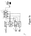
- FIG. 1 b is a block diagram of one embodiment for a real-time encoder system.
- FIG. 2 is a flow diagram of one embodiment for an overrun, catch-up encoder system.
- FIG. 3 is a block diagram of one embodiment for an MPEG video encoder.
- FIG. 4 is a block diagram of a second embodiment for an overrun catch-up encoder system.
- FIG. 5 is a flow diagram of one embodiment for determining catch-up levels within a catch-up controller of FIG. 4 .
- FIG. 6 is a timing diagram illustrating an overrun within an overrun catch-up encoder system.
- a system and method for processing an overrun in the encoding of an input bitstream are described.
- an overrun in the encoding of an input bitstream is determined and the severity of the overrun is determined.
- a current frame is encoded using a catch-up mode to process the overrun.
- the overrun catch-up encoder provides for limited overrun such that, in the worse-case, the encoder should run less than (n ⁇ T) timing periods to finish the input signal with timing length of T (wherein T is one frame time) and where n is a fixed constant.
- the embodiments provide that any catch-up levels should not cause further overrun.
- the embodiments provide that there must be a catch-up level, which can finish encoding within (1 ⁇ t) ⁇ T time even in the worse case, where t is a fixed number.
- n, t, and levels of catch-up mode may be chosen for each individual implementation where n is not infinitely large and t is not infinite small in order to optimize the overrun catch-up system.
- a software real-time MPEG video encoder is described.
- the encoder is designed to run in real-time with no frame dropping. If limited overrun is acceptable, the software encoder may use a more flexible algorithm to generate the best picture quality with limited hardware resources.
- the software real-time encoder may be designed to encode any compressive coding stream such as, for example, MOTION JPEG, MOTION JPEG-2000, DV, H.261, H.263, MPEG-4, and the like.
- the software real-time encoder system does not skip any input frames.
- the encoder may yield better quality than forcing the encoder to never overrun. As a result, the encoder may recover from the overrun without skipping input frames.
- the encoder system layer estimates the anticipated finishing time of the encoder and passes this information to the encoder.
- the encoder determines overrun situation using this information and the overrun situation is detected before next encoding start. Further, in catch-up mode, the encoder does not overrun again.
- multiple algorithms within the encoder speed up encoding with certain quality loss.
- the catch-up algorithm encodes the worse case signal faster than real-time.
- the rate control algorithm may be different than during normal processing. In this rate control algorithm, more bits may be used to avoid dramatic quality dropping.
- the catch-up may choose different catch-up levels to yield both short catch-up time and good catch-up quality.
- the encoder tries to use the normal encoding mode to determine if overrun has recovered without intervention. The encoder uses normal encoding mode during overrun as long as there is no input buffer overflow or output buffer underflow. If the buffer overflows a threshold amount, the encoder begins the catch-up mode without significant quality drop. If the encoder cannot recover from an overrun for a given period of time, the encoder begins the fast catch-up algorithm.
- the software encoder is designed to be normally optimal to process data in an encoding scheme with certain CPU load to the input source content sequence.
- each module of the software encoder is scheduled to process the input stream in a normal complexity for real-time encoding. Under limited CPU cycle resources, if the input source content characteristics exceed the predetermined encoding complexity, an overrun occurs. To get good encoding quality for normal input, overrun is unavoidable for a real-time software encoder. In existing encoder systems, skipping an input signal frame will cause permanent loss of this input data. However, such a loss is not acceptable. Therefore, in one embodiment, the encoder system supports overrun in normal mode and guarantees catch-up when overrun occurs.
- the present invention also relates to apparatus for performing the operations herein.
- This apparatus may be specially constructed for the required purposes, or it may comprise a general-purpose computer selectively activated or reconfigured by a computer program stored in the computer.
- a computer program may be stored in a computer readable storage medium, such as, but is not limited to, any type of disk including floppy disks, optical disks, CD-ROMs, and magnetic-optical disks, read-only memories (ROMs), random access memories (RAMs), EPROMs, EEPROMs, magnetic or optical cards, or any type of media suitable for storing electronic instructions, and each coupled to a computer system bus.
- FIG. 1 a is a block diagram of one embodiment for a computer architecture.
- computer system 180 includes an address/data bus 182 for communicating information, central processing unit (CPU) 184 coupled with bus 182 for processing information and instructions, volatile memory 186 (e.g., random access memory RAM) coupled with bus 182 for storing information and instructions for CPU 184 any nonvolatile memory 188 (e.g., read-only memory ROM) coupled with bus 182 for storing static information and instructions for CPU 184 .
- CPU 184 is a single processor having a single instruction pointer.
- Computer system 180 also includes a data storage device 190 (“disk subsystem”) such as, for example, a magnetic or optical disk or any storage device coupled with bus 182 for storing information instructions.
- Data storage device 190 includes one or more removable magnetic or optical storage media (for example, diskettes, tapes, or the like) which are computer readable memories.
- data storage device 190 may contain a bitstream of encoded information.
- Memory units of system 180 include 186 , 188 , and 190 .
- Computer system 180 may also include a signal input output communication device 192 (for example, modem, network interface card NIC) coupled to bus 182 for interfacing with other computer systems.
- signal input/output communication device 192 may receive an incoming encoded bitstream.
- Computer system 180 also includes an optional alphanumeric input device 194 including alphanumeric and function keys coupled to bus 182 for communicating information and command selections to CPU 184 .
- Computer system 180 also includes an optional cursor control or directing device 196 coupled to bus 182 for communicating user input information and command selections to CPU 184 .
- An optional display device 198 may also be coupled to bus 182 for displaying information to the computer user.
- Display device 198 may be a liquid crystal device, other flat-panel display, cathode ray tube, or other display device suitable for creating graphic images and alphanumeric characters recognizable to the user.
- Cursor control device 196 allows the computer user to dynamically signal a two-dimensional movement of a visible symbol (cursor) on a display screen or display device 198 .
- cursor control device 196 Many implementations of cursor control device 196 are well-known in the art including a trackball, mouse, touchpad, joystick, or special keys on alphanumeric input device 194 capable of signaling movement of a given direction or manner of displacement. Alternatively, it will be appreciated that the cursor may be directed or activated via input from alphanumeric input device 194 using special keys in key sequence commands. The present invention is also well suited to direct a cursor by other means such as, for example, voice commands.
- computer system 180 described herein illustrates an exemplary configuration of an operational platform upon which embodiments described herein may be implemented. Nevertheless, other computer systems with different configurations may also be used to place a computer system 180 within the scope of the embodiments.
- FIG. 1 b is a block diagram of one embodiment for a real-time encoder system 100 .
- input interface blocks 145 receive audio/video input signals.
- Encoder 115 encodes audio input signals and video input signals separately.
- video encoder 120 encodes video signals
- audio encoder 125 encodes audio signals.
- Multiplexer 130 multiplexes the compressed outputs of encoders 120 and 125 and sends the multiplexed signal to storage or transmission medium 160 . If there is local decoder output, local decoder output will be sent to the output unit.
- Timing and task control 135 synchronizes each encoder 120 and 125 to the input signal and with each other. In alternate embodiments, multiple encoders 115 may be utilized in one encoder system 100 .
- FIG. 2 is a flow diagram of one embodiment for an overrun, catch-up encoder system.
- the encoder system layer runs an output thread 222 that instructs the encoder threads 240 and 244 to execute by sending a message through the message queue EVx 228 and 238 , where x refers to the ordinal number of the scheduled encoder thread 240 and 244 respectively.
- the system may schedule two encoder threads 240 and 244 so x can either be 1 or 2.
- the message sent through the message queue EVx 228 238 from the system layer to the video encoder thread 240 and 244 contains a parameter T finish which is the expected finishing time of the encoder thread 240 and 244 .
- the message queue EVx 228 and 238 are shown in FIG.
- the execution frequency in “normal mode” of the encoder thread 240 and 244 is once per frame. “Normal mode” is defined as the mode in which no overrun occurs and the system can execute all scheduled threads in real-time.
- output thread 222 derives the parameter T finish each time a message is sent through EVx 228 and 238 to the encoder 115 .
- the derivation of T finish is done by predicting the time when the next video output interrupt will arrive at the system 100 .
- the combined execution time of all the threads being executed by the system is the time from the arrival of this interrupt to the start of the encoder thread 240 and 244 and is added as an offset to the predicted interrupt arrival time.
- the offset can be regarded as constant since the threads are (unlike the encoder thread) content-independent and always consume a constant number of execution cycles.
- the prediction of the interrupt arrival time may be calculated using standard time analysis prediction algorithms.
- the interrupt arrival time values are considered values of a time series.
- time series models such as the auto-regressive moving-average (ARMA) model, which can be utilized in the prediction process.
- ARMA auto-regressive moving-average
- Kalman filtering may be employed.
- Output thread 222 receives a feedback message through the message queue EVFx 230 and 236 from the encoder thread 240 and 244 respectively upon the encoder thread finishing processing.
- the availability of these feedback messages 230 and 236 determines whether the system identifies an overrun situation or not. However, encoder thread 240 and 244 recovers from the overrun situation as described below.
- the system layer only sends the expected thread finishing time T finish to the encoder thread 240 and 244 .
- FIG. 3 is a block diagram of one embodiment for an MPEG video encoder 120 .
- FIG. 3 is used to illustrate the process of determining multiple encoding levels.
- the encoding quality of encoder 120 depends on the complexity of encoding each input frame. For example, in a simple prediction between the current frame and an anchor frame, the predictive residual may be large and more bits are required to code the residual data of the frame. This means that bit rate control unit 322 should allocate more bits to the current frame to prevent the quality of the frame from dropping below a certain coding rate. Simple prediction leads to less computational complexity and allows fast encoding.
- entropy-coding unit 324 may drop unimportant data.
- entropy coding is less costly in CPU processing. If entropy coding drops data, the encoding quality will drop as well. However, encoder 120 will run faster and fewer bits are used for the frame.
- multiple of parameters may be used to make encoder 120 run faster. These parameters may be combined together to achieve multiple levels of fast encoding algorithms. In one embodiment, these levels consist of an overrun and catch-up algorithm set. In this embodiment, the best quality level may be used for normal encoding. This level may overrun as long as the maximum overrun to finish the input signal is less than (n ⁇ T) timing periods in which T is one frame time and n is a fixed constant. Further in this embodiment, for other than a normal encoding level, any subsequent level should not cause further overrun. Finally in this embodiment, there is at least one level that can finish encoding within (1 ⁇ t) ⁇ T time even in the worse case, where t is a fixed number. This level will be used for final catch-up.
- an MPEG video encoder 120 may have three encoding modes: normal encoding, level-1 catch-up mode, and level-2 catch-up mode.
- normal encoding mode the maximum encoding time of one video frame is (n ⁇ T), where T is one frame time.
- T the number of frame buffers for input and the number of frame buffers for output.
- level-1 catch-up mode encoder 120 finishes one frame in one frame time.
- level-2 catch-up mode encoder 120 finishes one frame in (1 ⁇ t) frame time, where t is a fixed number smaller than 1.
- encoder 120 includes memory buffers 302 and a set of procedures.
- Uncompressed video input signal is saved in input frame buffer 304 .
- Pre-processing unit 312 receives the input frames and pre-processes input video signal for better image quality. In this embodiment, the pre-processing may be noise reduction.
- the pre-processed frames are saved in pre-processing output frame buffer 306 .
- Buffer 306 is the input source of other encoding procedures.
- Temporal predict 314 receives the current frame in pre-processing output frame buffer 306 . Using other frames in pre-processing output frame buffer 306 and local decoder output buffer 308 , temporal predict 314 removes temporal redundancy in the current frame as much as possible. Typically, the redundancy portion is represented as motion vectors which are used for temporal prediction.
- Transform coding 318 applies a two-dimensional transformation such as, for example, discrete cosine transformation, and quantization to discover spatial redundancy within the residual value.
- Quantization within transform coding 318 is controlled by bit rate control 322 .
- bit rate control 322 In general, a higher quantization step size yields less number of symbols to encode and produces a poorer image quality as a less number of symbols may be encoded by less number of bits.
- the quantized transform coefficients and motion vectors are passed to entropy coding 324 .
- the entropy-coded symbols are output as coded video stream and saved in video stream buffer 310 .
- Entropy coding 324 also feeds back the number of bits already consumed to bit rate control 322 so that bit rate control 322 may adjust the quantization step size used by transform coding 318 to maintain the desired bit rate of the output video stream.
- Quantized transform coefficients are also passed from transform coding 318 to inverse transform 320 which applies inverse quantization and inverse transform on these coefficients similar to the procedures in the video decoder.
- Temporal prediction reconstruction 316 determines temporal prediction to emulate the temporal prediction in the decoder.
- Encoder 120 adds the residual value output from inverse transform coding 320 and the temporal prediction from temporal prediction reconstruction 316 . This sum is saved in local decoder output buffer 308 .
- the content of local decoder output buffer 308 will be the same as the output buffer on the decoder side.
- Encoder uses the frames in buffer 308 to perform temporal prediction for other frames.
- the temporal prediction on the encoder side will be the same as the temporal prediction on the decoder side.
- each encoder may have its own catch-up control unit or these encoders share one control unit.
- FIG. 4 is a block diagram of a second embodiment for an overrun catch-up encoder system 400 .
- encoder- 1 402 includes catch-up control unit 404 to handle overrun situations.
- the encoder system layer sends timing information to encoder- 1 402 so that encoder- 1 402 may detect if a previous encoding is overrun before encoder- 1 402 starts the current frame encoding. Based on the overrun status, catch-up controller 404 may choose correct encoding level for the current frame.
- FIG. 5 is a flow diagram of one embodiment for determining catch-up levels within catch-up controller 404 . In this embodiment, it is assumed that there is one normal encoding mode and two catch-up levels. Referring to FIG. 5 , at processing block 505 , it is determined if an overrun has occurred. If no overrun has occurred, processing continues as processing block 510 . At processing block 510 , the current frame is encoded using normal encoding mode.
- processing block 505 determines whether an overrun has occurred. If at processing block 505 it is determined that an overrun has occurred, processing continues at block 515 . At processing block 515 , it is determined if a minor overrun has occurred. If a minor overrun has occurred, then processing continues at block 520 .
- a minor overrun is, for example, an overrun of less that a half frame time.
- normal encoding or level-1 catch-up mode encoding is executed to process the overrun. If the system has extra frame buffers, for the minor overrun case, the encoder can still use normal encoding mode. Otherwise, the encoder can choose level-1 catch-up mode encoding to avoid further overrun which can cause buffer underflow or overflow.
- processing block 515 if the overrun is significant (for example, more than 1 frame time), then processing continues at block 525 .
- level-2 catch-up mode is executed to process the overrun.
- a long time overrun is determined by comparing the overrun time with a group-of-picture (GOP) time in which GOP time is the time required to process a set group of pictures (for example, 12). GOP length is the amount of data that may be encoded within a given time period. In this embodiment, the number of bits per picture is fixed. If the overrun is more than, for example, three frames, it will be difficult to maintain constant GOP codesize and level-2 mode encoding is requires. If a long time overrun is detected, processing continues at block 540 . At block 540 , level-2 catch-up mode is executed to process the overrun.
- GOP group-of-picture
- the bandwidth encoding may be desired to have the bandwidth encoding to occur at a fixed rate.
- the catch-up scenario uses a simpler encoding method with some kind of picture quality degradation for a limited period.
- the encoder chooses an encoding method generating higher data rates.
- processing block 535 If at processing block 535 , a long-time overrun is not detected, then processing continues at block 545 .
- level-1 catch-up mode is executed to process the overrun.
- FIG. 6 is a timing diagram illustrating an overrun.
- encoder 402 causes an overrun. However, at this time 604 , input buffer overflow and output buffer underflow have not occurred. In this example, normal encoding mode is used for the next frame with the prediction that the next frame encoding may recover the overrun. However, if the next frame causes further overrun at time 606 , the input and output buffer usage may be over the given threshold.
- Encoder 402 begins level-1 catch-up mode to process the overrun. In level-1 catch-up mode, because a subsequent overrun is not predicted, the buffer usage can be managed without overflow or underflow. However, encoder 402 may require a few frames to recover from the overrun. If this occurs, encoder 402 switches to level-2 catch-up mode at 616 and resumes normal mode after the overrun is processed.
Abstract
Description
Claims (20)
Priority Applications (1)
| Application Number | Priority Date | Filing Date | Title |
|---|---|---|---|
| US10/014,733 US6990144B2 (en) | 2000-12-11 | 2001-12-11 | System and method for overrun catch-up in a real-time software |
Applications Claiming Priority (2)
| Application Number | Priority Date | Filing Date | Title |
|---|---|---|---|
| US25483400P | 2000-12-11 | 2000-12-11 | |
| US10/014,733 US6990144B2 (en) | 2000-12-11 | 2001-12-11 | System and method for overrun catch-up in a real-time software |
Publications (2)
| Publication Number | Publication Date |
|---|---|
| US20020190888A1 US20020190888A1 (en) | 2002-12-19 |
| US6990144B2 true US6990144B2 (en) | 2006-01-24 |
Family
ID=26686433
Family Applications (1)
| Application Number | Title | Priority Date | Filing Date |
|---|---|---|---|
| US10/014,733 Expired - Lifetime US6990144B2 (en) | 2000-12-11 | 2001-12-11 | System and method for overrun catch-up in a real-time software |
Country Status (1)
| Country | Link |
|---|---|
| US (1) | US6990144B2 (en) |
Cited By (2)
| Publication number | Priority date | Publication date | Assignee | Title |
|---|---|---|---|---|
| RU2534370C2 (en) * | 2010-05-06 | 2014-11-27 | Ниппон Телеграф Энд Телефон Корпорейшн | Method and apparatus for controlling video coding |
| US9179165B2 (en) | 2010-05-07 | 2015-11-03 | Nippon Telegraph And Telephone Corporation | Video encoding control method, video encoding apparatus and video encoding program |
Citations (5)
| Publication number | Priority date | Publication date | Assignee | Title |
|---|---|---|---|---|
| US5760836A (en) * | 1996-08-22 | 1998-06-02 | International Business Machines Corporation | FIFO feedback and control for digital video encoder |
| US5862153A (en) * | 1995-09-29 | 1999-01-19 | Kabushiki Kaisha Toshiba | Coding apparatus and decoding apparatus for transmission/storage of information |
| US5960006A (en) * | 1994-09-09 | 1999-09-28 | Lsi Logic Corporation | MPEG decoding system adjusting the presentation in a predetermined manner based on the actual and requested decoding time |
| US6278735B1 (en) * | 1998-03-19 | 2001-08-21 | International Business Machines Corporation | Real-time single pass variable bit rate control strategy and encoder |
| US6763067B2 (en) * | 2000-10-10 | 2004-07-13 | Sarnoff Corporation | Rate control for bitstream re-encoding |
-
2001
- 2001-12-11 US US10/014,733 patent/US6990144B2/en not_active Expired - Lifetime
Patent Citations (5)
| Publication number | Priority date | Publication date | Assignee | Title |
|---|---|---|---|---|
| US5960006A (en) * | 1994-09-09 | 1999-09-28 | Lsi Logic Corporation | MPEG decoding system adjusting the presentation in a predetermined manner based on the actual and requested decoding time |
| US5862153A (en) * | 1995-09-29 | 1999-01-19 | Kabushiki Kaisha Toshiba | Coding apparatus and decoding apparatus for transmission/storage of information |
| US5760836A (en) * | 1996-08-22 | 1998-06-02 | International Business Machines Corporation | FIFO feedback and control for digital video encoder |
| US6278735B1 (en) * | 1998-03-19 | 2001-08-21 | International Business Machines Corporation | Real-time single pass variable bit rate control strategy and encoder |
| US6763067B2 (en) * | 2000-10-10 | 2004-07-13 | Sarnoff Corporation | Rate control for bitstream re-encoding |
Cited By (3)
| Publication number | Priority date | Publication date | Assignee | Title |
|---|---|---|---|---|
| RU2534370C2 (en) * | 2010-05-06 | 2014-11-27 | Ниппон Телеграф Энд Телефон Корпорейшн | Method and apparatus for controlling video coding |
| US9179154B2 (en) | 2010-05-06 | 2015-11-03 | Nippon Telegraph And Telephone Corporation | Video encoding control method and apparatus |
| US9179165B2 (en) | 2010-05-07 | 2015-11-03 | Nippon Telegraph And Telephone Corporation | Video encoding control method, video encoding apparatus and video encoding program |
Also Published As
| Publication number | Publication date |
|---|---|
| US20020190888A1 (en) | 2002-12-19 |
Similar Documents
| Publication | Publication Date | Title |
|---|---|---|
| US9918085B2 (en) | Media coding for loss recovery with remotely predicted data units | |
| US8121191B1 (en) | AVC to SVC transcoder | |
| JP5161130B2 (en) | Adaptive bandwidth footprint matching for multiple compressed video streams in fixed bandwidth networks | |
| US8861591B2 (en) | Software video encoder with GPU acceleration | |
| US7016547B1 (en) | Adaptive entropy encoding/decoding for screen capture content | |
| US9612965B2 (en) | Method and system for servicing streaming media | |
| US6333948B1 (en) | Video coding apparatus, video coding method and storage medium containing video coding program | |
| US9635374B2 (en) | Systems and methods for coding video data using switchable encoders and decoders | |
| US20030095603A1 (en) | Reduced-complexity video decoding using larger pixel-grid motion compensation | |
| US20120195356A1 (en) | Resource usage control for real time video encoding | |
| KR19980042224A (en) | MPEG decoder system and method with integrated memory for transport, decryption, system controller functions | |
| CN102291561A (en) | Reducing use of periodic key frames in video conferencing | |
| US8660191B2 (en) | Software video decoder display buffer underflow prediction and recovery | |
| JP2015171114A (en) | Moving image encoder | |
| KR20060131725A (en) | Video encoding device, video encoding control method, and video encoding control program | |
| KR20200058431A (en) | Transmission device, transmission method, and program | |
| US7403566B2 (en) | System, computer program product, and method for transmitting compressed screen images from one computer to another or many computers | |
| US20110299605A1 (en) | Method and apparatus for video resolution adaptation | |
| US6990144B2 (en) | System and method for overrun catch-up in a real-time software | |
| JP4447443B2 (en) | Image compression processor | |
| US6678418B2 (en) | Method and apparatus for buffer management in video processing | |
| JPH1174799A (en) | Processing method of variable length encoding data and buffer controller | |
| JP4745293B2 (en) | Image data encoding method, encoding apparatus, and decoding apparatus | |
| KR19990021920A (en) | Method and apparatus for generating on-screen display messages using stored bitstreams | |
| Chang | Maximizing qos for interactive dtv clients |
Legal Events
| Date | Code | Title | Description |
|---|---|---|---|
| FEPP | Fee payment procedure |
Free format text: PAYOR NUMBER ASSIGNED (ORIGINAL EVENT CODE: ASPN); ENTITY STATUS OF PATENT OWNER: LARGE ENTITY |
|
| AS | Assignment |
Owner name: SONY CORPORATION, JAPAN Free format text: ASSIGNMENT OF ASSIGNORS INTEREST;ASSIGNORS:TSUKAGOSHI, IKUO;WANG, JASON N.;ZIMMERMANN, KLAUS;AND OTHERS;REEL/FRAME:016555/0139;SIGNING DATES FROM 20020507 TO 20020602 Owner name: SONY ELECTRONICS INC., NEW JERSEY Free format text: ASSIGNMENT OF ASSIGNORS INTEREST;ASSIGNORS:TSUKAGOSHI, IKUO;WANG, JASON N.;ZIMMERMANN, KLAUS;AND OTHERS;REEL/FRAME:016555/0139;SIGNING DATES FROM 20020507 TO 20020602 |
|
| STCF | Information on status: patent grant |
Free format text: PATENTED CASE |
|
| FPAY | Fee payment |
Year of fee payment: 4 |
|
| FPAY | Fee payment |
Year of fee payment: 8 |
|
| AS | Assignment |
Owner name: SONY CORPORATION, JAPAN Free format text: ASSIGNMENT OF ASSIGNORS INTEREST;ASSIGNOR:SONY ELECTRONICS INC.;REEL/FRAME:036330/0420 Effective date: 20150731 |
|
| FPAY | Fee payment |
Year of fee payment: 12 |
|
| AS | Assignment |
Owner name: SATURN LICENSING LLC, NEW YORK Free format text: ASSIGNMENT OF ASSIGNORS INTEREST;ASSIGNOR:SONY CORPORATION;REEL/FRAME:048974/0222 Effective date: 20190108 |